EP0005960A1 - Load carrying decks - Google Patents
Load carrying decks Download PDFInfo
- Publication number
- EP0005960A1 EP0005960A1 EP79300924A EP79300924A EP0005960A1 EP 0005960 A1 EP0005960 A1 EP 0005960A1 EP 79300924 A EP79300924 A EP 79300924A EP 79300924 A EP79300924 A EP 79300924A EP 0005960 A1 EP0005960 A1 EP 0005960A1
- Authority
- EP
- European Patent Office
- Prior art keywords
- deck
- container
- flap
- buffer
- articles
- Prior art date
- Legal status (The legal status is an assumption and is not a legal conclusion. Google has not performed a legal analysis and makes no representation as to the accuracy of the status listed.)
- Granted
Links
- 239000011120 plywood Substances 0.000 description 6
- XAGFODPZIPBFFR-UHFFFAOYSA-N aluminium Chemical compound [Al] XAGFODPZIPBFFR-UHFFFAOYSA-N 0.000 description 4
- 229910052782 aluminium Inorganic materials 0.000 description 4
- 239000004411 aluminium Substances 0.000 description 4
- 238000001125 extrusion Methods 0.000 description 2
- 239000010410 layer Substances 0.000 description 2
- 238000010276 construction Methods 0.000 description 1
- 239000002356 single layer Substances 0.000 description 1
Images


Classifications
-
- B—PERFORMING OPERATIONS; TRANSPORTING
- B65—CONVEYING; PACKING; STORING; HANDLING THIN OR FILAMENTARY MATERIAL
- B65D—CONTAINERS FOR STORAGE OR TRANSPORT OF ARTICLES OR MATERIALS, e.g. BAGS, BARRELS, BOTTLES, BOXES, CANS, CARTONS, CRATES, DRUMS, JARS, TANKS, HOPPERS, FORWARDING CONTAINERS; ACCESSORIES, CLOSURES, OR FITTINGS THEREFOR; PACKAGING ELEMENTS; PACKAGES
- B65D90/00—Component parts, details or accessories for large containers
- B65D90/004—Contents retaining means
- B65D90/0073—Storage racks
-
- B—PERFORMING OPERATIONS; TRANSPORTING
- B60—VEHICLES IN GENERAL
- B60P—VEHICLES ADAPTED FOR LOAD TRANSPORTATION OR TO TRANSPORT, TO CARRY, OR TO COMPRISE SPECIAL LOADS OR OBJECTS
- B60P7/00—Securing or covering of load on vehicles
- B60P7/06—Securing of load
-
- B—PERFORMING OPERATIONS; TRANSPORTING
- B62—LAND VEHICLES FOR TRAVELLING OTHERWISE THAN ON RAILS
- B62D—MOTOR VEHICLES; TRAILERS
- B62D33/00—Superstructures for load-carrying vehicles
- B62D33/04—Enclosed load compartments ; Frameworks for movable panels, tarpaulins or side curtains
- B62D33/042—Enclosed load compartments ; Frameworks for movable panels, tarpaulins or side curtains divided into compartments
Abstract
Description
- This invention relates to a fold-away deck structure for use in a storage container. The container may be the load carrying part of a vehicle such as a box van or other truck or lorry.
- Such a container may often be used to carry around articles of a relatively low height which can not be stacked on top of one another due to their shape or because they are fragile. A single layer of articles on the floor of the container leaves much of the capacity of the ccntainer unused.
- One way of overcoming this problem is to provide a removeable deck which can be placed part way up the height of the container so that some articles can be stored on the floor of the container and others on the deck. In order to maintain the facility for carrying larger articles, the deck should be removeable. Complete removal of the deck is unsatisfactory in that the deck may not then be available when required. An alternative which has been proposed in United States Patent Specification 3,911,832 is for the deck to be foldable to a position at the edge of the container. When the articles to be carried are fragile and should not be allowed to come into contact with an unpadded interior of a container, it has previously been proposed to provide padding around the edges of the container. However. with a fold away deck, the deck would cover any padding and leave the necessarily rigid upper surface of the deck exposed to the interior of the container.
- A fold-away deck for a container in accordance with the invention comprises two portions which can be articulated so when the is folded away the top suface of that when the deck is folded away the top surface of one portion is exposed towards the interior of the container, characterised by the provision of a flap hinged to the one portion and comprising a deck surface and a buffer surface, said flap being moveable between a first position in which the deck surface is generally flush with and forms part of the top surface and a second position in which the buffer surface is exposed towards the interior of the container.
- Preferably each portion of the deck comprises two generally parallel spaced elongate members with a sheet member secured to a flange on each elongate member.
- Preferably the flap extends between the elongate members of the one portion and is supported on the flanges of said one portion when the flap is in the first position.
- The invention will now be described, by way of example only, with reference to the accompanying drawings in which:
- Figure 1 is a perspective view of a deck in accordance with the invention;
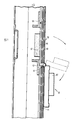
- Figure 2 is an elevational view of a portion of the deck of Figure 1 showing the flap; and
- Figure 3 is an elevational view of the deck as it is positioned within a container.
- A number of decks such as shown in Figure 1 are intended to be placed side by side within a container such as the load compartment of a box van which is illustrated diagrammatically as 117 in Figure 3. Each deck has an
outer deck section 11 and aninner deck section 13. The two deck portions are hinged to each other about anaxis 15 and to the inside surface of the container about an axis 71 to enable the deck to be stowed at the edge of the container as shown inposition 1 in Figure 3 or to extend across the container as shown inposition 3. When a series of decks are arranged across a container as shown in Figure 3, it is possible to load both the floor of the container and the deck with articles to be carried and for certain articles this can substantially increase the carrying capacity of the container. - The deck itself will now be described in greater detail with reference to Figures 1 and 2. The
outer deck portion 11 andinner deck portion 13 are hinged together about apivot axis 15. Theinner deck portion 13 comprises two parallelelongate members elongate member flange plywood sheet member 29 extends between the twoelongate members Flanges sheet 29 is flush with thebases outer deck portion 11 is of similar construction to theinner deck portion 13. It comprises two parallel spacedelongate aluminium extrusions flanges members members plywood sheet member 49jcins members flanges members deck members axis 15 by hinge pins passing through openings in the sides of the elongate members. The location of the hinge pins and the shape of the end portion ofmembers deck members - A
buffer flap 53, shown in greater detail in Figure 2 than in Figure 1, is provided within theplywood sheet member 49. Twoangle brackets outer deck member 11 at the extremities of an opening in theplywood sheet 49 provided for the buffer stop. At theangle bracket 57, which is the lower angle bracket when the deck is in a vertical position, thebuffer flap 53 is hinged by means of ahinge 61 to the remaining part of the deck. - The
flap 53 consists of analuminium base 65 which supports aplywood section 63 and arubber buffer 67. In the position of the flap where it is shown in detail in Figure 2, theplywood section 63 lies flush with and forms part of the deck surface. The rubber buffer is in the lower or inner side of the deck. When used as part of the deck surface, theflap 53 is supported with respect to the main body of the deck by itshinge 61 at one side and by theangle bracket 55 at the other side and along both edges byflanges flap 53 can swing from the position shown in detail through the position shown in dotted outline to the position shown in full outline. In this latter position, therubber buffer 67 is exposed on the outer .side of the deck and projects well beyond the general deck surface. - Referring to Figure 3 in greater detail, the assembly shown in three different positions. Figure 1 is the vertical position in which the
deck portions side wall 69 of the container. This leaves substantially the whole of the interior of the container available for large or bulky articles.Position 3 shows the deck in a horizontal position across the container and in this position some articles may be loaded on the floor of the container and other artieles on the deek.Position 2 is an intermediate position to illustrate the nature of movement betweenpositions - The various catches and mounting hinges by which the deck is positioned with the
container 117 will now be described. - The pivotal mounting of the
inner deck portion 13 to the side wall of the container is by means of a hinge 71 which consists of two plates 73 and 75 united by ahinge pin 74. Plate 73 is generally planar and is bolted to the top surface of theinner deck portion 13. The other plate 75 is of generally L-shape wfth the side of the L secured to the side wall of the container and the base of the L helping to support the load of the deck, particularly if free play develops in the hinge. The hinge is such that theinner portion 13 of the deck can pivot between thevertical position 1 and thehorizontal position 3 of Figure 3. - The deck can be held in its vertical position by cooperation between a
locking rail 87 and a pair of spring loadedcatches 89 arranged one in eachlongitudinal member catch 89 is slidable in itselongate member catch 89 engages behind a hooked end 91 of thebracket 87 and thereby retains theinner deck portion 13 in a vertical position. Theouter deck portion 11 then naturally hangs vertically adjacent the side wall of the container but may in addition be secured by straps or ropes to the side cf the container. - In order to move the deck from its vertical folded
position 1 of Figure 3 to thehorizontal position 3 of Figure 3 and to retain it in the horizontal position, a pair of catches at the outer or lower end of theouter deck portion 11 are used. The side wall of thecontainer 117 is equipped with a longitudinally extending extruded aluminium track 1C7 which is of top hat section with acentral portion 109 and twoouter flanges flanges central portion 109 clear of the side wall. A series of vertical slots are provided in the rail. This type of rail is provided for a variety of purposes in a conventional box van. For example, it assists in stiffening the flat sides of the container and due to the slots provides a convenient means for securing ropes and/or hooks to prevent articles moving around within the container. With this invention, two of the slots are engaged byhook members 97 which are positioned within theelongate members 37 and"39 of the outer deck portion and project from the outer end. These hook members are spring loaded into the interior of the elongate members ofouter deck member 11. - Thus in order to secure the deck in
position 3 of Figure 3, thecatch 89 is retracted to release theinner deck portion 13, theinner deck portion 13 is lowered and theouter deck portion 11 is raised through the position shown in Figure 2 until thehook members 97 engage in a slot in therail 107. Slight retraction of the hook member may be necessary to enter it into its slot. The central part of the deck is prevented from dropping below the horizontal position due to the fact that thepivot axis 15 is a considerable distance along theinner deck portion 13 from its outer end and the associated overlap between the elongate members of the inner and outer portions of the deck. - In
position 1, thebuffer flap 53 can be folded over so as to close the opening in the deck and provide a continuous deck surface for supporting a second layer of articles above a layer of articles on the floor of the container. Inposition 1, theflap 53 automatically swings down and out to expose therubber buffer 67. Thus when the container is to be used for taller articles which require the deck to be stowed inposition 1, the buffer prevents such articles from rubbing against sharp edges associated with other parts of the deck and thereby protects the article against damage. As a further security measure, straps or ropes may be used to hold articles against therubber buffer 67, such ropes being attached to appropriate locations at the side of the container through the opening left by the buffer stop.
Claims (3)
Applications Claiming Priority (2)
| Application Number | Priority Date | Filing Date | Title |
|---|---|---|---|
| GB2231978 | 1978-05-25 | ||
| GB2231978 | 1978-05-25 |
Publications (2)
| Publication Number | Publication Date |
|---|---|
| EP0005960A1 true EP0005960A1 (en) | 1979-12-12 |
| EP0005960B1 EP0005960B1 (en) | 1981-09-02 |
Family
ID=10177473
Family Applications (1)
| Application Number | Title | Priority Date | Filing Date |
|---|---|---|---|
| EP19790300924 Expired EP0005960B1 (en) | 1978-05-25 | 1979-05-24 | Load carrying decks |
Country Status (2)
| Country | Link |
|---|---|
| EP (1) | EP0005960B1 (en) |
| DE (1) | DE2960727D1 (en) |
Cited By (9)
| Publication number | Priority date | Publication date | Assignee | Title |
|---|---|---|---|---|
| US4786222A (en) * | 1987-05-11 | 1988-11-22 | Carvan, Inc. | Folding automobile storage deck assembly |
| WO1990008088A1 (en) * | 1989-01-12 | 1990-07-26 | T-W Management Corporation | Sectional van trailer having detachable, interchangeable compartments capable of forming a continuous van body with accompanying system for forming shelf decks and partition walls within cargo holding sections |
| EP0620148A2 (en) * | 1993-04-14 | 1994-10-19 | ANCRA Jungfalk GmbH | Vehicle loading surface structure with a support tube |
| US5375534A (en) * | 1993-05-24 | 1994-12-27 | Adams; Thomas F. | Intermediate deck structure for vehicles |
| EP0698545A1 (en) * | 1994-08-18 | 1996-02-28 | ACKERMANN-FRUEHAUF GmbH | Double-deck carriage |
| US5628596A (en) * | 1991-10-30 | 1997-05-13 | G & G Intellectual Properties, Inc. | Vehicle-carrying frame |
| GB2359803A (en) * | 2000-03-02 | 2001-09-05 | Paul Anthony Derry | Containers having support assemblies for the contents |
| US6585306B1 (en) | 2002-02-01 | 2003-07-01 | United Parcel Service Of America, Inc. | Interlocking deck support system |
| US6854400B2 (en) | 2002-05-21 | 2005-02-15 | United Parcel Service Of America, Inc. | Hinge and support system for an intermediate deck in a trailer |
Citations (2)
| Publication number | Priority date | Publication date | Assignee | Title |
|---|---|---|---|---|
| US3897971A (en) * | 1974-06-17 | 1975-08-05 | Ddt Inc | Trailer installation |
| US3911832A (en) * | 1973-09-10 | 1975-10-14 | Craft Ind Inc Van | Deck structure for vehicles |
-
1979
- 1979-05-24 EP EP19790300924 patent/EP0005960B1/en not_active Expired
- 1979-05-24 DE DE7979300924T patent/DE2960727D1/en not_active Expired
Patent Citations (2)
| Publication number | Priority date | Publication date | Assignee | Title |
|---|---|---|---|---|
| US3911832A (en) * | 1973-09-10 | 1975-10-14 | Craft Ind Inc Van | Deck structure for vehicles |
| US3897971A (en) * | 1974-06-17 | 1975-08-05 | Ddt Inc | Trailer installation |
Cited By (13)
| Publication number | Priority date | Publication date | Assignee | Title |
|---|---|---|---|---|
| US4786222A (en) * | 1987-05-11 | 1988-11-22 | Carvan, Inc. | Folding automobile storage deck assembly |
| WO1990008088A1 (en) * | 1989-01-12 | 1990-07-26 | T-W Management Corporation | Sectional van trailer having detachable, interchangeable compartments capable of forming a continuous van body with accompanying system for forming shelf decks and partition walls within cargo holding sections |
| US5628596A (en) * | 1991-10-30 | 1997-05-13 | G & G Intellectual Properties, Inc. | Vehicle-carrying frame |
| EP0620148A3 (en) * | 1993-04-14 | 1996-12-18 | Jungfalk Ancra Gmbh | Vehicle loading surface structure with a support tube. |
| EP0620148A2 (en) * | 1993-04-14 | 1994-10-19 | ANCRA Jungfalk GmbH | Vehicle loading surface structure with a support tube |
| US5375534A (en) * | 1993-05-24 | 1994-12-27 | Adams; Thomas F. | Intermediate deck structure for vehicles |
| US5452972A (en) * | 1993-05-24 | 1995-09-26 | Adams; Thomas E. | Intermediate deck structure for vehicles |
| EP0698545A1 (en) * | 1994-08-18 | 1996-02-28 | ACKERMANN-FRUEHAUF GmbH | Double-deck carriage |
| GB2359803A (en) * | 2000-03-02 | 2001-09-05 | Paul Anthony Derry | Containers having support assemblies for the contents |
| GB2359803B (en) * | 2000-03-02 | 2004-01-14 | Paul Anthony Derry | Supporting articles within a container |
| US6585306B1 (en) | 2002-02-01 | 2003-07-01 | United Parcel Service Of America, Inc. | Interlocking deck support system |
| US6854400B2 (en) | 2002-05-21 | 2005-02-15 | United Parcel Service Of America, Inc. | Hinge and support system for an intermediate deck in a trailer |
| US7549380B2 (en) | 2002-05-21 | 2009-06-23 | United Parcel Service Of America, Inc. | Hinge and support system for an intermediate deck in a trailer |
Also Published As
| Publication number | Publication date |
|---|---|
| DE2960727D1 (en) | 1981-11-26 |
| EP0005960B1 (en) | 1981-09-02 |
Similar Documents
| Publication | Publication Date | Title |
|---|---|---|
| US5902000A (en) | Vehicle bed extender | |
| US4915439A (en) | Tarpaulin support structure | |
| CA1335090C (en) | Vehicle mountable luggage carrier assembly | |
| US5452972A (en) | Intermediate deck structure for vehicles | |
| US5383703A (en) | Modular trailer | |
| US4846487A (en) | Tailgate step for pickup trucks | |
| US5275301A (en) | Collapsible freight container with gates | |
| US6644708B1 (en) | Reconfigurable drop panels for a vehicle cargo bed | |
| US5366124A (en) | Vehicle bed load container and stabilizer | |
| US5816638A (en) | Pickup truck bed extender, ramp and tailgate | |
| US6634848B2 (en) | Automotive stowable ramp device | |
| JP4199190B2 (en) | Hinge and support system for intermediate deck in trailer | |
| US6585306B1 (en) | Interlocking deck support system | |
| US5348207A (en) | Vehicle top carrier | |
| US20060076794A1 (en) | Truck bed extension | |
| US2338955A (en) | Automobile carrier | |
| US6007127A (en) | Tailgate cargo container | |
| EP0005960B1 (en) | Load carrying decks | |
| US6827231B2 (en) | Minivan box liner | |
| US7178848B1 (en) | Utility rack arrangement for a vehicle | |
| US20040050889A1 (en) | Cargo management system useful as a table | |
| US4293158A (en) | Gate with ramp device for livestock trailer with lift deck | |
| CA1106809A (en) | Carrier for motor vehicle | |
| JPS61115744A (en) | Method of transportation of passenger car | |
| US20020121795A1 (en) | Deck lock system |
Legal Events
| Date | Code | Title | Description |
|---|---|---|---|
| PUAI | Public reference made under article 153(3) epc to a published international application that has entered the european phase |
Free format text: ORIGINAL CODE: 0009012 |
|
| AK | Designated contracting states |
Designated state(s): DE GB IT NL |
|
| 17P | Request for examination filed | ||
| ITF | It: translation for a ep patent filed |
Owner name: JACOBACCI & PERANI S.P.A. |
|
| GRAA | (expected) grant |
Free format text: ORIGINAL CODE: 0009210 |
|
| AK | Designated contracting states |
Designated state(s): DE GB IT NL |
|
| REF | Corresponds to: |
Ref document number: 2960727 Country of ref document: DE Date of ref document: 19811126 |
|
| PGFP | Annual fee paid to national office [announced via postgrant information from national office to epo] |
Ref country code: DE Payment date: 19840525 Year of fee payment: 6 |
|
| PGFP | Annual fee paid to national office [announced via postgrant information from national office to epo] |
Ref country code: NL Payment date: 19860531 Year of fee payment: 8 |
|
| PG25 | Lapsed in a contracting state [announced via postgrant information from national office to epo] |
Ref country code: NL Effective date: 19871201 |
|
| NLV4 | Nl: lapsed or anulled due to non-payment of the annual fee | ||
| PG25 | Lapsed in a contracting state [announced via postgrant information from national office to epo] |
Ref country code: DE Effective date: 19880202 |
|
| GBPC | Gb: european patent ceased through non-payment of renewal fee | ||
| PG25 | Lapsed in a contracting state [announced via postgrant information from national office to epo] |
Ref country code: GB Free format text: LAPSE BECAUSE OF NON-PAYMENT OF DUE FEES Effective date: 19881118 |
|
| PLBE | No opposition filed within time limit |
Free format text: ORIGINAL CODE: 0009261 |
|
| STAA | Information on the status of an ep patent application or granted ep patent |
Free format text: STATUS: NO OPPOSITION FILED WITHIN TIME LIMIT |