EP0005894B1 - Exciter apparatus and method for rotating chain or track bushings by combining static and dynamic torque - Google Patents
Exciter apparatus and method for rotating chain or track bushings by combining static and dynamic torque Download PDFInfo
- Publication number
- EP0005894B1 EP0005894B1 EP79300492A EP79300492A EP0005894B1 EP 0005894 B1 EP0005894 B1 EP 0005894B1 EP 79300492 A EP79300492 A EP 79300492A EP 79300492 A EP79300492 A EP 79300492A EP 0005894 B1 EP0005894 B1 EP 0005894B1
- Authority
- EP
- European Patent Office
- Prior art keywords
- links
- bushing
- pair
- track
- torque
- Prior art date
- Legal status (The legal status is an assumption and is not a legal conclusion. Google has not performed a legal analysis and makes no representation as to the accuracy of the status listed.)
- Expired
Links
- 238000000034 method Methods 0.000 title claims description 6
- 230000003068 static effect Effects 0.000 title description 2
- 238000011065 in-situ storage Methods 0.000 claims description 4
- 230000033001 locomotion Effects 0.000 claims description 4
- 210000005069 ears Anatomy 0.000 description 4
- 238000005299 abrasion Methods 0.000 description 1
- 125000004122 cyclic group Chemical group 0.000 description 1
- 238000011161 development Methods 0.000 description 1
- 230000018109 developmental process Effects 0.000 description 1
- 239000012530 fluid Substances 0.000 description 1
- 238000005461 lubrication Methods 0.000 description 1
- 238000012423 maintenance Methods 0.000 description 1
- 239000011435 rock Substances 0.000 description 1
- 238000005201 scrubbing Methods 0.000 description 1
Images
Classifications
-
- B—PERFORMING OPERATIONS; TRANSPORTING
- B62—LAND VEHICLES FOR TRAVELLING OTHERWISE THAN ON RAILS
- B62D—MOTOR VEHICLES; TRAILERS
- B62D55/00—Endless track vehicles
- B62D55/32—Assembly, disassembly, repair or servicing of endless-track systems
-
- Y—GENERAL TAGGING OF NEW TECHNOLOGICAL DEVELOPMENTS; GENERAL TAGGING OF CROSS-SECTIONAL TECHNOLOGIES SPANNING OVER SEVERAL SECTIONS OF THE IPC; TECHNICAL SUBJECTS COVERED BY FORMER USPC CROSS-REFERENCE ART COLLECTIONS [XRACs] AND DIGESTS
- Y10—TECHNICAL SUBJECTS COVERED BY FORMER USPC
- Y10S—TECHNICAL SUBJECTS COVERED BY FORMER USPC CROSS-REFERENCE ART COLLECTIONS [XRACs] AND DIGESTS
- Y10S29/00—Metal working
- Y10S29/046—Vibration
Definitions
- the invention relates to chains, such as conveyor chains, but particularly crawler tracks of track-laying vehicles, and of the kind comprising pairs of links pivotally interconnected to adjacent pairs of links by track pins with bushings encircling respective ones of the track pins.
- the bushings extend laterally between links of a pair and are engaged by drive sprockets to drive the chains and, in the case of a crawler track, provide locomotion for the vehicle.
- apparatus for rotating a bushing of a chain comprising pairs of links pivotally interconnected to adjacent pairs of links by track pins with bushings encircling respective ones of the track pins and the ends of each bushing being press fitted to respective ends of a pair of the links, the apparatus comprising torque means for applying a torque to the bushing and being characterised by a first member securable to one link of the pair; a second member securable to the other link of the pair and exciter means interconnecting the first and second members for providing a vibratory motion therebetween.
- the invention also includes a method of servicing in situ a chain comprising pairs of links pivotally interconnected to adjacent pairs of links by track pins with bushings encircling respective ones of the track pins and the ends of each bushing being press fitted to respective ends of a pair of the links, the method comprising applying a torque to one of the bushings to rotate the bushing to bring a different part of the bushing into a sprocket-engaging position, characterised by the step of vibrating the links of the pair relatively to one another while applying th.e torque.
- the applied vibration is a substantially resonant vibration.
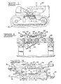
- FIG. 1 Shown in Figure 1 is a track-laying vehicle 10 which utilizes an apparatus 12 interconnecting adjacent track bushings of a track 14 of the vehicle, with the track 14 in place and fully assembled.
- This apparatus 12 is in accordance with that shown in Figure 5 of the above-cited U.S. Patent Specification No. 3,915,036, and described in the specification.
- such apparatus 12 is disposed inwardly of the track 14, with a rod end 16 of a cylinder or jack 18 thereof engaging with a bushing 20.
- the extension of such jack 18 pivots an arm 22 affixed to clamp means 24 which are in turn associated with a bushing 26.
- An insert 28 slidably mounted to the clamp means 24 is seated in the worn area of the bushing 26. It will be seen that through extension of the jack 18, the bushing 26 may be turned to rotate such bushing 26, with the track 14 in situ in its fully assembled state.
- each housing i.e., for example, bushing 26 shown in Figure 3
- each housing is press-fitted into bores 30, 32 of the respective adjacent ends of respective ones of a pair of links 34, 36.
- a pin 38 is movably disposed within such bushing 26, and has the ends thereof press-fitted into bores 40, 42 in the ends of respective ones of an adjacent pair of links 44, 46, so that the links 34, 36 are pivotally mounted relatively to the links 44, 46.
- a first member 48 is secured to the link 34 by means of bolts and nuts 50, and a second member 52 is secured to the link 36 by means of bolts and nuts 54, these links 34, 36 being in generally side-by-side relation so that the members 48, 52 are in generally side-by-side relation.
- the member 48 is made up of an elongate main member portion 56 running generally along the link 34, and a limb 58 extending therefrom in perpendicular fashion, across the chain, so as to be generally L-shaped in configuration.
- the member 52 is made up of an elongate main member portion 60 positioned generally along the link 36, and a limb 62 extending therefrom and generally perpendicular thereto, so as to be generally L-shaped in configuration.
- the limbs 58, 62 are in opposed relation, and upwardly directed ears 64 extend from the limb 58, and upwardly directed ears 66 extend from the limb 62.
- a fluid pressure operated cylinder apparatus 68 interconnects the ears 64, 66, in turn fixed to the limbs 58, 62, so that the cylinder apparatus 68 in the broad sense interconnects the limbs 58, 62 of the members 48, 52.
- the apparatus 68 includes a body 70 and extendable and retractable rods 72, 74 which are actually pivotally secured to the respective ears 64, 66.
- the rods 72, 74 Upon extension of the rods 72, 74 from the body 70, it will be seen that one of the links 34, 36 tends to rock relative to the other through the force applied to the members 48, 52. Similarly, retraction of the rods 72, 74 tends to pivot the links 34, 36 relatively oppositely through pivoting of the members 48, 52.
- Masses 76 and 78 are secured to each of members 48 and 52, respectively, and are used to tune the natural frequency of the system to a frequency that is within a range that is low enough to be attained through the excitement of the cylinder apparatus 68.
Landscapes
- Engineering & Computer Science (AREA)
- Chemical & Material Sciences (AREA)
- Combustion & Propulsion (AREA)
- Transportation (AREA)
- Mechanical Engineering (AREA)
- Springs (AREA)
- Devices For Conveying Motion By Means Of Endless Flexible Members (AREA)
Applications Claiming Priority (2)
| Application Number | Priority Date | Filing Date | Title |
|---|---|---|---|
| US909148 | 1978-05-24 | ||
| US05/909,148 US4202224A (en) | 1978-05-24 | 1978-05-24 | Apparatus for rotating of track bushing by combined static and dynamic torque |
Publications (2)
| Publication Number | Publication Date |
|---|---|
| EP0005894A1 EP0005894A1 (en) | 1979-12-12 |
| EP0005894B1 true EP0005894B1 (en) | 1981-08-05 |
Family
ID=25426704
Family Applications (1)
| Application Number | Title | Priority Date | Filing Date |
|---|---|---|---|
| EP79300492A Expired EP0005894B1 (en) | 1978-05-24 | 1979-03-27 | Exciter apparatus and method for rotating chain or track bushings by combining static and dynamic torque |
Country Status (3)
| Country | Link |
|---|---|
| US (1) | US4202224A (enExample) |
| EP (1) | EP0005894B1 (enExample) |
| JP (1) | JPS54153439A (enExample) |
Families Citing this family (3)
| Publication number | Priority date | Publication date | Assignee | Title |
|---|---|---|---|---|
| US4554720A (en) * | 1984-08-13 | 1985-11-26 | Caterpillar Tractor Co. | Apparatus and method for turning a track bushing |
| US5693051A (en) * | 1993-07-22 | 1997-12-02 | Ethicon Endo-Surgery, Inc. | Electrosurgical hemostatic device with adaptive electrodes |
| US20050023897A1 (en) * | 2003-07-31 | 2005-02-03 | Anderton Peter W. | Method and apparatus for rebuilding track assembly |
Family Cites Families (4)
| Publication number | Priority date | Publication date | Assignee | Title |
|---|---|---|---|---|
| JPS4964542A (enExample) * | 1972-10-25 | 1974-06-22 | ||
| US3915036A (en) * | 1973-04-09 | 1975-10-28 | Caterpillar Tractor Co | Track bushing turning tool |
| US4002090A (en) * | 1973-04-09 | 1977-01-11 | Caterpillar Tractor Co. | Track bush turning tool |
| US4050141A (en) * | 1975-09-29 | 1977-09-27 | Caterpillar Tractor Co. | Track bush turning tool |
-
1978
- 1978-05-24 US US05/909,148 patent/US4202224A/en not_active Expired - Lifetime
-
1979
- 1979-03-27 EP EP79300492A patent/EP0005894B1/en not_active Expired
- 1979-05-11 JP JP5717179A patent/JPS54153439A/ja active Granted
Also Published As
| Publication number | Publication date |
|---|---|
| JPS54153439A (en) | 1979-12-03 |
| JPS6212075B2 (enExample) | 1987-03-16 |
| US4202224A (en) | 1980-05-13 |
| EP0005894A1 (en) | 1979-12-12 |
Similar Documents
| Publication | Publication Date | Title |
|---|---|---|
| AU584182B2 (en) | Method and apparatus for tensioning frictionally driven, ground engaging belts | |
| US3492054A (en) | Track hinge joints with rotating bushings | |
| US3960412A (en) | Wear-compensating replacement sprocket | |
| US3357750A (en) | Hinged track | |
| JPH05213237A (ja) | トラックチェーンジョイントの保持方法及び装置 | |
| CA2327224A1 (en) | Method and apparatus for retaining a track chain joint | |
| EP0005894B1 (en) | Exciter apparatus and method for rotating chain or track bushings by combining static and dynamic torque | |
| EP0426673B1 (en) | Tensioning and recoil system for a tracked vehicle | |
| US4050141A (en) | Track bush turning tool | |
| US3915036A (en) | Track bushing turning tool | |
| US6076901A (en) | Track shoe for an endless track vehicle | |
| US4257653A (en) | Track assembly for track-type vehicles with dual link assemblies | |
| US4035036A (en) | Noise suppressing element for continuous track of crawler type vehicle and method of operating same | |
| US4002090A (en) | Track bush turning tool | |
| EP3814204B1 (en) | Track assembly for a machine | |
| US4277876A (en) | Method for rotating a track chain bushing | |
| US4128932A (en) | Method for turning a track bushing | |
| US4187744A (en) | Apparatus for rotating track chain bushing | |
| US5016945A (en) | Arrangement for connecting and moving the plates of a caterpillar track of earth-moving machines | |
| US5730280A (en) | Plate link chain | |
| JP2022527887A (ja) | 軌道チェーン及びブッシング回転方法 | |
| AU2840301A (en) | Device for lifting a caterpillar road wheel | |
| CA1128586A (en) | Anti torsion means for track assemblies for track type vehicles and methods | |
| US1913098A (en) | Endless track for tractors | |
| US6299558B1 (en) | Drive mechanism having bogies |
Legal Events
| Date | Code | Title | Description |
|---|---|---|---|
| PUAI | Public reference made under article 153(3) epc to a published international application that has entered the european phase |
Free format text: ORIGINAL CODE: 0009012 |
|
| 17P | Request for examination filed | ||
| AK | Designated contracting states |
Designated state(s): GB IT |
|
| ITF | It: translation for a ep patent filed | ||
| GRAA | (expected) grant |
Free format text: ORIGINAL CODE: 0009210 |
|
| AK | Designated contracting states |
Designated state(s): GB IT |
|
| REG | Reference to a national code |
Ref country code: GB Ref legal event code: 732 |
|
| ITPR | It: changes in ownership of a european patent |
Owner name: CESSIONE;CATERPILLAR INC. |
|
| ITTA | It: last paid annual fee | ||
| PGFP | Annual fee paid to national office [announced via postgrant information from national office to epo] |
Ref country code: GB Payment date: 19910218 Year of fee payment: 13 |
|
| PG25 | Lapsed in a contracting state [announced via postgrant information from national office to epo] |
Ref country code: GB Effective date: 19920327 |
|
| GBPC | Gb: european patent ceased through non-payment of renewal fee | ||
| PLBE | No opposition filed within time limit |
Free format text: ORIGINAL CODE: 0009261 |
|
| STAA | Information on the status of an ep patent application or granted ep patent |
Free format text: STATUS: NO OPPOSITION FILED WITHIN TIME LIMIT |