EP0005023B1 - Steam generator tubesheet face machining apparatus - Google Patents
Steam generator tubesheet face machining apparatus Download PDFInfo
- Publication number
- EP0005023B1 EP0005023B1 EP19790300582 EP79300582A EP0005023B1 EP 0005023 B1 EP0005023 B1 EP 0005023B1 EP 19790300582 EP19790300582 EP 19790300582 EP 79300582 A EP79300582 A EP 79300582A EP 0005023 B1 EP0005023 B1 EP 0005023B1
- Authority
- EP
- European Patent Office
- Prior art keywords
- turntable
- tubesheet
- bearing race
- steam generator
- machining
- Prior art date
- Legal status (The legal status is an assumption and is not a legal conclusion. Google has not performed a legal analysis and makes no representation as to the accuracy of the status listed.)
- Expired
Links
Images

Classifications
-
- F—MECHANICAL ENGINEERING; LIGHTING; HEATING; WEAPONS; BLASTING
- F22—STEAM GENERATION
- F22B—METHODS OF STEAM GENERATION; STEAM BOILERS
- F22B37/00—Component parts or details of steam boilers
- F22B37/002—Component parts or details of steam boilers specially adapted for nuclear steam generators, e.g. maintenance, repairing or inspecting equipment not otherwise provided for
-
- B—PERFORMING OPERATIONS; TRANSPORTING
- B23—MACHINE TOOLS; METAL-WORKING NOT OTHERWISE PROVIDED FOR
- B23B—TURNING; BORING
- B23B3/00—General-purpose turning-machines or devices, e.g. centre lathes with feed rod and lead screw; Sets of turning-machines
- B23B3/22—Turning-machines or devices with rotary tool heads
- B23B3/26—Turning-machines or devices with rotary tool heads the tools of which perform a radial movement; Rotary tool heads thereof
- B23B3/265—Surfacing or grooving flanges
Definitions
- This invention relates to apparatus for effecting retubing of a steam generator in a nuclear power plant.
- Nuclear reactor power plants utilize a steam generator having a tube bundle to transfer heat from a primary side reactor-heated-liquid to water on a secondary side to form steam for driving a turbine.
- Condenser leaks in the power plants have caused circulating water, which is often brackish, to mix with the secondary-side water in the steam generator, resulting in the build-up of undesirable chemicals in the tube bundle.
- Water treatment and blowdown have not completely protected the steam generator tubes from corrosion and leaks.
- the desirability of replacement or repair of the steam generator increases. Since removal of a steam generator intact from a nuclear power plant requires removal of a large portion of a reinforced concrete containment vessel, replacement of such generator in such manner becomes time consuming, expensive, and therefore undesirable.
- the present invention resides in apparatus for machining the face of a tubesheet disposed in a steam generator shell from which the tubes have been removed, said apparatus being mounted on primary support means welded to the inner wall of said steam generator shell, and secondary support means removably attached to said primary support means, characterized in that said secondary support means consists of a large diameter anti-friction bearing having a non-rotatable outer bearing race mounted on a support ring with adjustable centering means and a rotatable inner bearing race carrying a circular turntable which is parallel to the tubesheet face and removably attached at its outer periphery to said rotatable inner bearing race, said turntable having a machining tool assembly disposed on a face thereof adjacent to said tubesheet for machining the corresponding face thereof during rotaty movement of said turntable, said machining tool having a head which is radially movable on said turntable, said turntable having power operated drive means for turning said turntable during operation of said machining tool assembly.
- the steam generator 1 with which the tubesheet face machining apparatus of the present invention is intended to be employed in connection with replacement of the tube bundle 23 therein typically includes a vertically oriented shell 3 having a lower cylindrical portion 5, an upper cylindrical portion 7, larger in diameter than the lower portion, and a frustoconical transition portion 9 joining the lower and upper portions 5 and 7.
- a tubesheet 11 is disposed in the lower end of the lower portion 5 of the shell and has a plurality of holes 12 for accommodating the ends of U-shaped tubes 13 which extend upwardly from the tubesheet 11 and are closely packed to form the tube bundle 23 disposed vertically within the lower portion 5 of the shell 3.
- a hemispherical channel head 15 is fastened to the tubesheet 11 and has a divider plate 17 disposed therein.
- a primary fluid inlet nozzle 19 supplies heated affluent primary fluid from a nuclear reactor core (not shown) to one portion of the channel head 1 5 and a discharge nozzle 21 is disposed in the channel head 1 5 to return the affluent primary fluid to such reactor core.
- a plurality of support plates 25 are disposed throughout the tube bundle 23 to support the tubes 13 at various locations along their length to reduce flow-induced vibrations.
- Antivibration bars 27 are also disposed adjacent to the bends in the tubes 13 to prevent vibration in this portion of the tube bundle 23.
- a wrapper or sleeve 29 is disposed between the tube bundle 23 and the shell 3 so as to form an annular space 31 therebetween.
- the upper part of the upper section 7 of the shell as shown in Figure 1 has been removed to gain access to the interior of the steam generator in preparation for removal and replacement of the tube bundle therein.
- Various components of the steam generator usually disposed in the upper section 7 of the shell 3 also have been removed from the steam generator as shown in Figure 1 to provide access to the top of the sleeve 29 encircling the tube bundle 23.
- Typical operation of the steam generator which per se forms no part of the present invention, involves the flow of heated primary fluid from a nuclear reactor core upwardly through the tubesheet 11 and one branch of the U-shaped tube bundle 23 and downwardly through the other branch of such tube bundle and back through the tubesheet 11 to the discharge nozzle 21, while secondary fluid above the tubesheet 11 and outside the tube bundle 23 becomes heated to form steam for conveyance by conduit means (not shown) to a turbine (not shown) operated by such steam.
- the machining apparatus of the present invention is affiliated with the lower section 5 of the shell 3 of the steam generator shown in Figure 1, for machining the upper surface 40 of the tubesheet 11 disposed in such steam generator.
- such apparatus comprises a face milling cutter assembly 41 carried on the lower face of a turntable 42 disposed above and parallel to the upper surface 40 of the tubesheet 11.
- a milling cutter head 44 at the lower end of the cutter assembly 41 is caused to machine a circular path on the upper surface 40 of the tubesheet 11.
- the milling cutter assembly 41 depends from a circular mounting member 45 adapted to assume different lockable rotary positions about a vertical pivot axis 46 located on the turntable 42 at one side of its axis of rotation 43.
- the cutter assembly 41 is so constructed and arranged that the cutter head 44 occupies the position near the outer periphery of the circular mounting member 45 so that as the rotary position of such mounting member is changed about its pivot axis 46, the radial position of the milling cutter head 44 with respect to the turntable axis 43 is also correspondingly changed.
- the path along which such cutter head 44 may be positioned about the pivot axis 46 is shown schematically in Figure 3 as the circular dot-dash line 46.
- the pivot axis 46 for the mounting member 45 may be defined by a vertical shaft 48 extending downwardly from the turntable.
- a plurality of manually-actuable locking screws 49 are provided that include finger members 50 co-operable with a shoulder 51 in the mounting member 45 to urge such member into locking engagement with a machined surface on the underside of the turntable 42.
- Operating personnel located above the turntable 42 may effect such repositioning of the mounting member 45 for the cutter assembly 41, including locking and unlocking the screws 49 manually, by way of a plurality of through openings 52 extending downwardly through the turntable 42.
- the cutter assembly 41 includes such as an hydraulic drive motor 53 operatively connected to the cutter head 44 through the medium of a gear drive mechanism 54.
- the motor 53, gear mechanism 54, and cutter head 44 are mounted on vertical guide members 55 affiliated with a downwardly extending pedestal part of the assembly to permit adjustment in the vertical positioning of the cutter head 44 to control depth of cut, for example, during machining of the upper surface 40 of the tubesheet 11.
- a rack and pinion arrangement 56 operated by a hand wheel 57 is provided.
- Locking screws 58 provide for securing the cutter head 44 and its drive members in selected vertical positions on the guide members 55.
- the depth of cut adjustment for the cutter head 44 as effected through operation of the hand wheel 57 and of the locking screws 58 will be effectuated manually by way of the through openings 52 in the turntable 42; the rate of rotation of such turntable during operation of the equipment being relatively slow so that the depth of cut adjustment can be made during such turntable rotation, if desired.
- the turntable 42 is adapted for turning movement about the central axis of the steam generator shell 3 by way of a large diameter ball bearing assembly 60 having an inner race 61 bolted to the top of the turntable 42 at its outer periphery and an outer annular race 62 that is bolted to the top of a support ring 63 that encircles the turntable 42.
- the support ring 63 includes an annular flange portion 64 that either directly or indirectly rests on a plurality of support lugs 65 that are welded to the interior of the steam generator shell 3 and disposed in spaced-apart circular array at a selected height above the upper surface 40 of the tubesheet 11.
- the machining apparatus of the present invention is adapted to be employed with different steam generator shell diameters, such as thirty-three inch, fifty-one inch, forth-four inch, etc.
- the annular flange 64 of the support ring 63 will rest directly on top of the support lugs 65 welded to the generator shell as shown in the left-hand portion of the drawing in Figure 2.
- spacer members 66 removably attached to the lugs 65 welded to the tube shell 3, as shown in the right-hand portion of the drawing of Figure 2, the machining apparatus can be adapted for operation in the larger sizes of such generator shell.
- a plurality of jack screws 70 are provided for centering of the support ring 63 within the shell 3, and thereby centering the turntable 42 coaxially within such shell.
- the apparatus For effecting turning of the turntable 42 to obtain the feeding of the rotating cutter head 44 along its circular paths atop the tubesheet 11, the apparatus is provided with a drive gear 71 operated by a motor 72 mounted on the outer ring 62 of the ball bearing assembly.
- the drive gear 71 co-operates with teeth 75 formed in the inner periphery of the inner race 61 of the ball bearing assembly 60.
- the mounting member 45 may be reconfigured and made positionable along a straight-line radial path 80 on the turntable 42 to change the radius of the circular cutting path taken by the cutter head 44 during machining operation.
Landscapes
- Engineering & Computer Science (AREA)
- Mechanical Engineering (AREA)
- Physics & Mathematics (AREA)
- High Energy & Nuclear Physics (AREA)
- Thermal Sciences (AREA)
- General Engineering & Computer Science (AREA)
- Monitoring And Testing Of Nuclear Reactors (AREA)
- Turning (AREA)
- Milling Processes (AREA)
Description
- This invention relates to apparatus for effecting retubing of a steam generator in a nuclear power plant.
- Nuclear reactor power plants utilize a steam generator having a tube bundle to transfer heat from a primary side reactor-heated-liquid to water on a secondary side to form steam for driving a turbine. Condenser leaks in the power plants have caused circulating water, which is often brackish, to mix with the secondary-side water in the steam generator, resulting in the build-up of undesirable chemicals in the tube bundle. Water treatment and blowdown have not completely protected the steam generator tubes from corrosion and leaks. As the number of tubes subject to such leaks increases, the desirability of replacement or repair of the steam generator increases. Since removal of a steam generator intact from a nuclear power plant requires removal of a large portion of a reinforced concrete containment vessel, replacement of such generator in such manner becomes time consuming, expensive, and therefore undesirable.
- In on-site retubing of a nuclear plant steam generator, it has been proposed, for example, to remove a top portion of the steam generator shell to gain access to the tube bundle for removing same. Following removal of the tube bundle tubes for replacement, the faces of the tubesheet must be reconditioned and this must be done remotely, since the area within the steam generator shell is radioactive.
- It is therefore the principal object of the present invention to provide an apparatus which can perform such operation by automatic or remote control.
- With this object in view, the present invention resides in apparatus for machining the face of a tubesheet disposed in a steam generator shell from which the tubes have been removed, said apparatus being mounted on primary support means welded to the inner wall of said steam generator shell, and secondary support means removably attached to said primary support means, characterized in that said secondary support means consists of a large diameter anti-friction bearing having a non-rotatable outer bearing race mounted on a support ring with adjustable centering means and a rotatable inner bearing race carrying a circular turntable which is parallel to the tubesheet face and removably attached at its outer periphery to said rotatable inner bearing race, said turntable having a machining tool assembly disposed on a face thereof adjacent to said tubesheet for machining the corresponding face thereof during rotaty movement of said turntable, said machining tool having a head which is radially movable on said turntable, said turntable having power operated drive means for turning said turntable during operation of said machining tool assembly.
- The invention will become more readily apparent from the following description of a preferred embodiment thereof shown, by way of example only, in the accompanying drawings, in which:
- Figure 1 is a vertical perspective view of the tube-containing portion of a nuclear power plant steam generator shown partially in section;
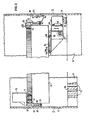
- Figure 2 is a vertical view partly in outline and partly in section, showing a preferred embodiment of the present invention affiliated with the shell and tubesheet of a steam generator such as shown in Figure 1 from which the tube bundle depicted in such Figure 1 has been removed;
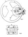
- Figure 3 is a bottom view of the apparatus of Figure 1; and
- Figure 4 is an alternate mounting arrangement for a machining tool assembly of the apparatus of Figures 2 and 3.
- Referring to Figure 1 in the drawings, the steam generator 1 with which the tubesheet face machining apparatus of the present invention is intended to be employed in connection with replacement of the
tube bundle 23 therein typically includes a verticallyoriented shell 3 having a lowercylindrical portion 5, an uppercylindrical portion 7, larger in diameter than the lower portion, and a frustoconical transition portion 9 joining the lower andupper portions lower portion 5 of the shell and has a plurality ofholes 12 for accommodating the ends ofU-shaped tubes 13 which extend upwardly from the tubesheet 11 and are closely packed to form thetube bundle 23 disposed vertically within thelower portion 5 of theshell 3. - A
hemispherical channel head 15 is fastened to the tubesheet 11 and has a divider plate 17 disposed therein. A primaryfluid inlet nozzle 19 supplies heated affluent primary fluid from a nuclear reactor core (not shown) to one portion of the channel head 1 5 and adischarge nozzle 21 is disposed in the channel head 1 5 to return the affluent primary fluid to such reactor core. - A plurality of
support plates 25 are disposed throughout thetube bundle 23 to support thetubes 13 at various locations along their length to reduce flow-induced vibrations.Antivibration bars 27 are also disposed adjacent to the bends in thetubes 13 to prevent vibration in this portion of thetube bundle 23. - A wrapper or
sleeve 29 is disposed between thetube bundle 23 and theshell 3 so as to form anannular space 31 therebetween. The upper part of theupper section 7 of the shell as shown in Figure 1 has been removed to gain access to the interior of the steam generator in preparation for removal and replacement of the tube bundle therein. Various components of the steam generator usually disposed in theupper section 7 of theshell 3 also have been removed from the steam generator as shown in Figure 1 to provide access to the top of thesleeve 29 encircling thetube bundle 23. - Typical operation of the steam generator, which per se forms no part of the present invention, involves the flow of heated primary fluid from a nuclear reactor core upwardly through the tubesheet 11 and one branch of the
U-shaped tube bundle 23 and downwardly through the other branch of such tube bundle and back through the tubesheet 11 to thedischarge nozzle 21, while secondary fluid above the tubesheet 11 and outside thetube bundle 23 becomes heated to form steam for conveyance by conduit means (not shown) to a turbine (not shown) operated by such steam. - Referring to Figures 2 and 3 in the drawings, the machining apparatus of the present invention is affiliated with the
lower section 5 of theshell 3 of the steam generator shown in Figure 1, for machining theupper surface 40 of the tubesheet 11 disposed in such steam generator. In accordance with the presently preferred embodiment, such apparatus comprises a facemilling cutter assembly 41 carried on the lower face of aturntable 42 disposed above and parallel to theupper surface 40 of the tubesheet 11. By rotation of theturntable 42 about its central axis 43, amilling cutter head 44 at the lower end of thecutter assembly 41 is caused to machine a circular path on theupper surface 40 of the tubesheet 11. Themilling cutter assembly 41 depends from acircular mounting member 45 adapted to assume different lockable rotary positions about avertical pivot axis 46 located on theturntable 42 at one side of its axis of rotation 43. Thecutter assembly 41 is so constructed and arranged that thecutter head 44 occupies the position near the outer periphery of thecircular mounting member 45 so that as the rotary position of such mounting member is changed about itspivot axis 46, the radial position of themilling cutter head 44 with respect to the turntable axis 43 is also correspondingly changed. The path along whichsuch cutter head 44 may be positioned about thepivot axis 46 is shown schematically in Figure 3 as the circular dot-dash line 46. It will be understood that in each selected rotary position of thecutter head 44 about thepivot axis 46 ofmounting member 45, theturntable 42 will make at least one turn about its central axis 43 to cause a circular machining cut to be made on theupper surface 40 of the tubesheet 11. By suitable choice of such rotary positions for thecutter 44 about thepivot axis 46 and the corresponding choice of rotations of theturntable 42 about its central axis 43 the entire upper surface of the tubesheet 11 may be scanned by the cutter head. - The
pivot axis 46 for themounting member 45 may be defined by avertical shaft 48 extending downwardly from the turntable. To lock thecircular mounting member 45 in any one of its selected rotary positions about thepivot axis 46, a plurality of manually-actuable locking screws 49 are provided that includefinger members 50 co-operable with ashoulder 51 in themounting member 45 to urge such member into locking engagement with a machined surface on the underside of theturntable 42. Operating personnel (not shown) located above theturntable 42 may effect such repositioning of themounting member 45 for thecutter assembly 41, including locking and unlocking thescrews 49 manually, by way of a plurality of throughopenings 52 extending downwardly through theturntable 42. - The
cutter assembly 41 includes such as anhydraulic drive motor 53 operatively connected to thecutter head 44 through the medium of agear drive mechanism 54. Themotor 53,gear mechanism 54, andcutter head 44 are mounted on vertical guide members 55 affiliated with a downwardly extending pedestal part of the assembly to permit adjustment in the vertical positioning of thecutter head 44 to control depth of cut, for example, during machining of theupper surface 40 of the tubesheet 11. To facilitate such vertical adjustment a rack and pinion arrangement 56 operated by ahand wheel 57 is provided.Locking screws 58 provide for securing thecutter head 44 and its drive members in selected vertical positions on the guide members 55. It would be appreciated that the depth of cut adjustment for thecutter head 44 as effected through operation of thehand wheel 57 and of thelocking screws 58 will be effectuated manually by way of the throughopenings 52 in theturntable 42; the rate of rotation of such turntable during operation of the equipment being relatively slow so that the depth of cut adjustment can be made during such turntable rotation, if desired. - The
turntable 42 is adapted for turning movement about the central axis of thesteam generator shell 3 by way of a large diameter ball bearing assembly 60 having aninner race 61 bolted to the top of theturntable 42 at its outer periphery and an outerannular race 62 that is bolted to the top of asupport ring 63 that encircles theturntable 42. Thesupport ring 63 includes anannular flange portion 64 that either directly or indirectly rests on a plurality ofsupport lugs 65 that are welded to the interior of thesteam generator shell 3 and disposed in spaced-apart circular array at a selected height above theupper surface 40 of the tubesheet 11. The machining apparatus of the present invention is adapted to be employed with different steam generator shell diameters, such as thirty-three inch, fifty-one inch, forth-four inch, etc. In the case of the smaller diameter, theannular flange 64 of thesupport ring 63 will rest directly on top of thesupport lugs 65 welded to the generator shell as shown in the left-hand portion of the drawing in Figure 2. By the use ofspacer members 66 removably attached to thelugs 65 welded to thetube shell 3, as shown in the right-hand portion of the drawing of Figure 2, the machining apparatus can be adapted for operation in the larger sizes of such generator shell. For centering of thesupport ring 63 within theshell 3, and thereby centering theturntable 42 coaxially within such shell, a plurality ofjack screws 70 are provided. - For effecting turning of the
turntable 42 to obtain the feeding of the rotatingcutter head 44 along its circular paths atop the tubesheet 11, the apparatus is provided with adrive gear 71 operated by amotor 72 mounted on theouter ring 62 of the ball bearing assembly. Thedrive gear 71 co-operates withteeth 75 formed in the inner periphery of theinner race 61 of the ball bearing assembly 60. - It will be apparent from the foregoing that other tools may be substituted for the
milling cutter head 44. For example, in some circumstances it may be desirable to provide for reboring of thetube holes 12 in the tubesheet 11, in which case a drilling or boring tool would be substituted for the facemilling cutter head 44. - Referring to Figure 4, rather than being turnable about the
pivot axis 46, themounting member 45 may be reconfigured and made positionable along a straight-lineradial path 80 on theturntable 42 to change the radius of the circular cutting path taken by thecutter head 44 during machining operation.
Claims (3)
Applications Claiming Priority (2)
| Application Number | Priority Date | Filing Date | Title |
|---|---|---|---|
| US89686978A | 1978-04-17 | 1978-04-17 | |
| US896869 | 1978-04-17 |
Publications (3)
| Publication Number | Publication Date |
|---|---|
| EP0005023A2 EP0005023A2 (en) | 1979-10-31 |
| EP0005023A3 EP0005023A3 (en) | 1979-11-14 |
| EP0005023B1 true EP0005023B1 (en) | 1982-01-13 |
Family
ID=25406988
Family Applications (1)
| Application Number | Title | Priority Date | Filing Date |
|---|---|---|---|
| EP19790300582 Expired EP0005023B1 (en) | 1978-04-17 | 1979-04-09 | Steam generator tubesheet face machining apparatus |
Country Status (4)
| Country | Link |
|---|---|
| EP (1) | EP0005023B1 (en) |
| JP (1) | JPS54142682A (en) |
| DE (1) | DE2961803D1 (en) |
| ES (1) | ES479663A1 (en) |
Families Citing this family (3)
| Publication number | Priority date | Publication date | Assignee | Title |
|---|---|---|---|---|
| US4515747A (en) * | 1982-09-27 | 1985-05-07 | Combustion Engineering, Inc. | Remotely operated maintenance and inspection equipment transporter |
| FR2538727A1 (en) * | 1982-12-29 | 1984-07-06 | Dufieux R | Machining unit for performing machining operations on workpieces of cylindrical or conical shape. |
| US4614466A (en) * | 1984-06-01 | 1986-09-30 | The United States Of America As Represented By The Secretary Of The Air Force | Damaged radar radome repair device |
Family Cites Families (2)
| Publication number | Priority date | Publication date | Assignee | Title |
|---|---|---|---|---|
| US3630109A (en) * | 1970-02-16 | 1971-12-28 | Atlantic Richfield Co | Portable facing and grooving machine |
| DE2636246C2 (en) * | 1976-08-12 | 1982-09-16 | Brown Boveri Reaktor GmbH, 6800 Mannheim | Method for finding material defects in the wall of a reactor pressure vessel |
-
1979
- 1979-04-09 EP EP19790300582 patent/EP0005023B1/en not_active Expired
- 1979-04-09 DE DE7979300582T patent/DE2961803D1/en not_active Expired
- 1979-04-17 ES ES479663A patent/ES479663A1/en not_active Expired
- 1979-04-17 JP JP4614779A patent/JPS54142682A/en active Pending
Also Published As
| Publication number | Publication date |
|---|---|
| JPS54142682A (en) | 1979-11-07 |
| DE2961803D1 (en) | 1982-02-25 |
| EP0005023A3 (en) | 1979-11-14 |
| EP0005023A2 (en) | 1979-10-31 |
| ES479663A1 (en) | 1980-05-16 |
Similar Documents
| Publication | Publication Date | Title |
|---|---|---|
| US4840096A (en) | Device for machining chamfers on a free of a pipe | |
| US4297061A (en) | Steam generator shell parting method and apparatus | |
| KR950004660B1 (en) | Apparatus for machining a valve's seat | |
| US7092477B2 (en) | BWR inspection manipulator | |
| US4362447A (en) | Steam generator tubesheet face machining apparatus | |
| EP2979803B1 (en) | Treatment apparatus for waste steam generator | |
| KR940004831B1 (en) | Appratus and method for removing thermocouples from nuclear reactor vessel | |
| US5687205A (en) | Underwater remote drilling tool and methods | |
| EP3153266B1 (en) | Tube cutting device having conical fitting member to cut tube of waste steam generator and cutting method | |
| EP0100355A1 (en) | Portable machine tool for preparing pipe joints for welding | |
| US4657450A (en) | Machining tool for pipes | |
| EP0005023A2 (en) | Steam generator tubesheet face machining apparatus | |
| US5158739A (en) | Device for dismantling an irradiated component of a nuclear reactor by machining its wall | |
| US5070600A (en) | Tool positioning assembly | |
| US5307661A (en) | System and method for shot peening reactor vessel penetrations | |
| JPH0755985A (en) | In-situ cleaning system for inlet mixer | |
| KR820001680B1 (en) | Steam generator tube sheet face machining apparatus | |
| US4419847A (en) | Device for supporting and moving a tool within a tapping | |
| US4649609A (en) | Apparatus and process for providing an alternate coolant path in the core of a nuclear reactor | |
| EP0001893B1 (en) | Internal tube cutters | |
| US6540455B1 (en) | Machine and method for circumferentially milling a cylindrical work piece | |
| KR900000591B1 (en) | Method & apparatus for machining a groove around a tubular member | |
| KR20070072412A (en) | Process for the repair of at least one connecting area between a partition plate and a tube plate of a water chamber of a heat exchanger | |
| RU2504851C1 (en) | Cutting machine of caissons with defective irradiated fuel assemblies | |
| US4616497A (en) | Rotopeening method |
Legal Events
| Date | Code | Title | Description |
|---|---|---|---|
| PUAI | Public reference made under article 153(3) epc to a published international application that has entered the european phase |
Free format text: ORIGINAL CODE: 0009012 |
|
| PUAL | Search report despatched |
Free format text: ORIGINAL CODE: 0009013 |
|
| AK | Designated contracting states |
Designated state(s): CH DE FR GB IT SE |
|
| AK | Designated contracting states |
Designated state(s): CH DE FR GB IT SE |
|
| 17P | Request for examination filed | ||
| ITF | It: translation for a ep patent filed | ||
| GRAA | (expected) grant |
Free format text: ORIGINAL CODE: 0009210 |
|
| AK | Designated contracting states |
Designated state(s): CH DE FR GB IT SE |
|
| REF | Corresponds to: |
Ref document number: 2961803 Country of ref document: DE Date of ref document: 19820225 |
|
| PGFP | Annual fee paid to national office [announced via postgrant information from national office to epo] |
Ref country code: CH Payment date: 19830207 Year of fee payment: 5 |
|
| PGFP | Annual fee paid to national office [announced via postgrant information from national office to epo] |
Ref country code: FR Payment date: 19830208 Year of fee payment: 5 |
|
| PGFP | Annual fee paid to national office [announced via postgrant information from national office to epo] |
Ref country code: SE Payment date: 19830228 Year of fee payment: 5 |
|
| PGFP | Annual fee paid to national office [announced via postgrant information from national office to epo] |
Ref country code: DE Payment date: 19830630 Year of fee payment: 4 |
|
| PG25 | Lapsed in a contracting state [announced via postgrant information from national office to epo] |
Ref country code: DE Effective date: 19840103 |
|
| PG25 | Lapsed in a contracting state [announced via postgrant information from national office to epo] |
Ref country code: SE Effective date: 19840410 |
|
| PG25 | Lapsed in a contracting state [announced via postgrant information from national office to epo] |
Ref country code: CH Effective date: 19840430 |
|
| GBPC | Gb: european patent ceased through non-payment of renewal fee | ||
| PG25 | Lapsed in a contracting state [announced via postgrant information from national office to epo] |
Ref country code: FR Free format text: LAPSE BECAUSE OF NON-PAYMENT OF DUE FEES Effective date: 19841228 |
|
| REG | Reference to a national code |
Ref country code: CH Ref legal event code: PL |
|
| REG | Reference to a national code |
Ref country code: FR Ref legal event code: ST |
|
| PG25 | Lapsed in a contracting state [announced via postgrant information from national office to epo] |
Ref country code: GB Effective date: 19881118 |
|
| EUG | Se: european patent has lapsed |
Ref document number: 79300582.8 Effective date: 19850417 |
|
| PLBE | No opposition filed within time limit |
Free format text: ORIGINAL CODE: 0009261 |
|
| STAA | Information on the status of an ep patent application or granted ep patent |
Free format text: STATUS: NO OPPOSITION FILED WITHIN TIME LIMIT |