EP0004779A2 - Apparatus for applying electrical connectors to cables - Google Patents
Apparatus for applying electrical connectors to cables Download PDFInfo
- Publication number
- EP0004779A2 EP0004779A2 EP79300558A EP79300558A EP0004779A2 EP 0004779 A2 EP0004779 A2 EP 0004779A2 EP 79300558 A EP79300558 A EP 79300558A EP 79300558 A EP79300558 A EP 79300558A EP 0004779 A2 EP0004779 A2 EP 0004779A2
- Authority
- EP
- European Patent Office
- Prior art keywords
- connector
- ram
- housing
- cable
- aligning
- Prior art date
- Legal status (The legal status is an assumption and is not a legal conclusion. Google has not performed a legal analysis and makes no representation as to the accuracy of the status listed.)
- Granted
Links
- 239000004020 conductor Substances 0.000 claims abstract description 15
- 238000003780 insertion Methods 0.000 claims description 15
- 230000037431 insertion Effects 0.000 claims description 15
- 230000008878 coupling Effects 0.000 claims 2
- 238000010168 coupling process Methods 0.000 claims 2
- 238000005859 coupling reaction Methods 0.000 claims 2
- 230000013011 mating Effects 0.000 description 7
- 238000010008 shearing Methods 0.000 description 5
- 238000009413 insulation Methods 0.000 description 4
- 230000004888 barrier function Effects 0.000 description 3
- 230000006835 compression Effects 0.000 description 2
- 238000007906 compression Methods 0.000 description 2
- 230000000717 retained effect Effects 0.000 description 2
- 238000002788 crimping Methods 0.000 description 1
- 239000011810 insulating material Substances 0.000 description 1
- 239000002184 metal Substances 0.000 description 1
- 238000000034 method Methods 0.000 description 1
- 229920000515 polycarbonate Polymers 0.000 description 1
- 239000004417 polycarbonate Substances 0.000 description 1
- 125000006850 spacer group Chemical group 0.000 description 1
Images


Classifications
-
- H—ELECTRICITY
- H01—ELECTRIC ELEMENTS
- H01R—ELECTRICALLY-CONDUCTIVE CONNECTIONS; STRUCTURAL ASSOCIATIONS OF A PLURALITY OF MUTUALLY-INSULATED ELECTRICAL CONNECTING ELEMENTS; COUPLING DEVICES; CURRENT COLLECTORS
- H01R43/00—Apparatus or processes specially adapted for manufacturing, assembling, maintaining, or repairing of line connectors or current collectors or for joining electric conductors
- H01R43/01—Apparatus or processes specially adapted for manufacturing, assembling, maintaining, or repairing of line connectors or current collectors or for joining electric conductors for connecting unstripped conductors to contact members having insulation cutting edges
-
- Y—GENERAL TAGGING OF NEW TECHNOLOGICAL DEVELOPMENTS; GENERAL TAGGING OF CROSS-SECTIONAL TECHNOLOGIES SPANNING OVER SEVERAL SECTIONS OF THE IPC; TECHNICAL SUBJECTS COVERED BY FORMER USPC CROSS-REFERENCE ART COLLECTIONS [XRACs] AND DIGESTS
- Y10—TECHNICAL SUBJECTS COVERED BY FORMER USPC
- Y10T—TECHNICAL SUBJECTS COVERED BY FORMER US CLASSIFICATION
- Y10T29/00—Metal working
- Y10T29/51—Plural diverse manufacturing apparatus including means for metal shaping or assembling
- Y10T29/5147—Plural diverse manufacturing apparatus including means for metal shaping or assembling including composite tool
- Y10T29/5148—Plural diverse manufacturing apparatus including means for metal shaping or assembling including composite tool including severing means
-
- Y—GENERAL TAGGING OF NEW TECHNOLOGICAL DEVELOPMENTS; GENERAL TAGGING OF CROSS-SECTIONAL TECHNOLOGIES SPANNING OVER SEVERAL SECTIONS OF THE IPC; TECHNICAL SUBJECTS COVERED BY FORMER USPC CROSS-REFERENCE ART COLLECTIONS [XRACs] AND DIGESTS
- Y10—TECHNICAL SUBJECTS COVERED BY FORMER USPC
- Y10T—TECHNICAL SUBJECTS COVERED BY FORMER US CLASSIFICATION
- Y10T29/00—Metal working
- Y10T29/53—Means to assemble or disassemble
- Y10T29/5313—Means to assemble electrical device
- Y10T29/532—Conductor
- Y10T29/53209—Terminal or connector
- Y10T29/53213—Assembled to wire-type conductor
- Y10T29/53235—Means to fasten by deformation
-
- Y—GENERAL TAGGING OF NEW TECHNOLOGICAL DEVELOPMENTS; GENERAL TAGGING OF CROSS-SECTIONAL TECHNOLOGIES SPANNING OVER SEVERAL SECTIONS OF THE IPC; TECHNICAL SUBJECTS COVERED BY FORMER USPC CROSS-REFERENCE ART COLLECTIONS [XRACs] AND DIGESTS
- Y10—TECHNICAL SUBJECTS COVERED BY FORMER USPC
- Y10T—TECHNICAL SUBJECTS COVERED BY FORMER US CLASSIFICATION
- Y10T29/00—Metal working
- Y10T29/53—Means to assemble or disassemble
- Y10T29/5313—Means to assemble electrical device
- Y10T29/53261—Means to align and advance work part
Definitions
- This invention relates in general to the art of making electrical line connections and relates in particular to apparatus for applying electrical connectors to cables.
- each connector comprising an insulating housing having a cable receiving end, an end opposite thereto, a cable receiving cavity opening into the cable receiving end, and a contact member
- the apparatus comprising a connector application station, means actuable to feed the carrier strip towards the application station to position the leading connector of the carrier strip at the application station, a ram assembly mounted for reciprocating movement towards and away from the application station, and tooling on the ram assembly, for deforming the housing and for applying a force to the contact member electrically to connect it to a conductor of a cable that has been inserted into the cable receiving cavity.
- Such known apparatus are for use with electrical connectors of the "pre-insulated” type and which comprise a tubular metal crimping ferrule surrounded by a housing in the form of a tubular insulating sleeve.
- the tooling of the known apparatus is thus adapted to crimp the connector to a cable end which has been stripped of insulation and which has been inserted into the ferrule and thus into the cable-receiving cavity of the housing, the sleeve and the ferrule being deformed by the tooling as the ram is driven towards the connector application station, so that the ferrule makes permanent electrical contact with the electrically conductive core of the cable.
- the present application is directed to the problem of applying to a cable, an electrical Connector in which the contact member is partially inserted into a wall of the housing adjacent to the opposite end thereof, an inwardly deformable cable strain relief portion of the housing being disposed between the contact member and the cable receiving end of the housing.
- the cable is inserted into the cable receiving cavity of the housing after which, the cable strain relief portion is inwardly deformed to grip the cable and thus to clamp it in position and the contact member is subsequently driven home into the housing to make electrical contact with the cable core.
- the connector is intended to be inserted when it has been applied to the cable end, into a female connector having means to make electrical contact with an exposed surface of the contact member.
- Such connectors are known per se from United States Patent Specification No. 3,954,320, for example.
- the present invention is intended to provide apparatus capable of handling these connectors when in strip form and of applying them to cables at a single connector application station, despite the problems that exist of aligning the connectors automatically with appropriate application tooling of the apparatus.
- apparatus as defined in the second paragraph of this specification are characterised in that for the application to cables of a strip of electrical connectors in which the contact member of each connector is partially inserted into a wall of the housing adjacent to the opposite end thereof, an inwardly deformable cable strain relief portion of the housing of the connector being disposed between the contact member and the cable receiving end of the_housing;
- the tooling comprises a deforming tool for the inward deformation of the strain relief portion, connector aligning means, and an insertion tool adapted to drive the contact member home into the wall of the housing to make electrical contact with the conductor of the cable, the connector aligning surfaces projecting beyond the deforming and insertion tools towards the connector application station, and being effective as the ram assembly moves towards such station to align the leading connector in two transverse directions with the deforming and insertion tools;
- Electrical connectors 2 (shown in perspective view in Figures 1 and 2) for use in the telephone industry, in particular in telephone hand sets, are intended each to be applied to an end of a cable 4 which comprises four juxtaposed insulated conductors 8 (one of which is shown in Figures 7 to 9) contained within a cable sheath 6.
- a connector 2 When a connector 2 is to be installed on the end of a cable 4 a portion of the cable sheath 6 is removed to expose the conductors 8 although the insulation is not stripped from the conductors 8 themselves.
- Each connector 2 comprises a substantially rectangular housing 10 of insulating material, for example polycarbonate, the housing 10 having a cable-receiving end 12, a mating end 14, a top wall 16, a bottom wall 18, and parallel side walls 20.
- a cable-receiving cavity 22 extending inwardly from the cable-receiving end 12 towards the mating end 14, comprises an enlarged portion 13 adjacent to the end 12 and which merges with a portion 24 of reduced cross-section adjacent to the mating end 14.
- the portion 24 is dimensioned to receive only the conductors 8, the portion 13 being dimensioned to receive the end portion of the sheath 6 of the cable 4.
- the top wall 16 is provided with first and second strain relief portions 26 and 28, respectively, which are intended to be deformed inwardly of the housing 10 as shown in Figures 8 and 9, to clamp the sheath 6 and the individual conductors 8 in the housing lO, to provide a secure mechanical connection between the cable 4 and the connector 2.
- Each connector 2 also comprises four uniplanar contact.members 30 each lodged in a through opening 31 ( Figures 6 to 8) in the top wall 16 adjacent to the mating end 14 of the connector. The members 30 can be driven home into the openings 31 to pierce the insulation of the conductors 8 so as to make electrical contact with the electrical conductive cores thereof. Between the openings 31 are barriers 33 which are so dimensioned that when the contact members 30 have been driven home into the openings 31, the upper edges 32 of the contact members 30 are exposed, but adjacent contact members 30 are insulated from each other by the barriers 33. The edges 32 are engageable by contact spring members (not shown) in a receptacle (not shown) in which the connector 2 is adapted to be latched in mating relationship by means of a latch arm 34 projecting from the wall 18 of the housing 10.
- the apparatus to be described is intended to apply connectors 2 in the form of a continuous strip 1 to the ends of cables 4.
- the connectors 2 of the strip 1 are joined by a carrier strip 36 from which the connectors 2 extend in constantly spaced relationship lengthwise of the strip 36, each connector 2 being joined to the strip 36 by a connecting lug 38 formed integrally with the strip 36 and with the housing 10 of the connector 2.
- the apparatus has a C-shaped frame 40 comprising a base 42 joined to an upper arm 46 (best seen in Figure 3) by a neck 48.
- the base 42 is mounted on the platen 50 of a conventional bench press operated by a pedal switch (not shown).
- a press ram 184 of the bench press is directly coupled to a second ram 164 of a ram assembly of the apparatus, so as to be indirectly coupled to a first ram 132 of the ram assembly as described in detail below.
- the bench press is not otherwise shown.
- a connector application station 52 at which a connector 2 is supported during its application to a cable 4.
- the strip of connectors 2 is fed to the station 52 over a leftwardly (as seen in Figure 3) extending feed plate 54 on the upper surface of which is a connector feed track 55 which serves to guide the connector strip 1 along the plate 54 from a rotary storage reel (not shown) to the station 52.
- the strip 1 is intermittently fed during each operating cycle of the apparatus, to position the leading connector 2 of the strip 1 at the station 52, by a reciprocating feed finger 56 connected by a pivot pin 58 to a yoke 60 on a piston rod 62, the finger 56 being biased in a clockwise (as seen in Figure 3) direction by a torsion spring (not shown) surrounding the pivot pin 58.
- the piston rod 52 extends from a pneumatic cylinder 64 which is supplied with compressed air by air lines 65.
- the cylinder 64 is suspended by means of a mounting bracket 66 from a screw 68 which is rotatably supported in a bracket 70, the screw 66 being axially immovable with respect thereto, the limits of the stroke of the feed finger 56 being thereby adjustable by rotating the screw 68.
- the cylinder 64 is clamped to the bracket 70 by means of a screw 72 which is threaded through the bracket 70 and into the bracket 66.
- the bracket 70 is secured by means of a fastener 74 to a plate 76 which in turn is secured by fasteners to a plate 78 which extends leftwardly from (as seen in Figure 3), and is formed integrally with, the arm 46 of the frame 40.
- a mounting block 80 is fixed to the base 42, a cover plate 82 being secured to the upper (as seen in Figures 4 and 5) surface of the block 80.
- a fixed shear block 84 is also secured to the block 80 on the forward i.e. the leftward (as seen in Figure 4) face 85 thereof by fasteners 86 ( Figure 3).
- a fixed anvil assembly 88 formed integrally with the feed plate 54, is mounted on the base 42 in front of, and below the shear block 84 and comprises an anvil block 90 having a recess 92 in its upper (as seen in Figure 4) surface to provide clearance for the latch arm 34 of the leading connector 2 at the station 52, the bottom wall 18 of the connector 2 adjacent to the mating end 14 thereof being supported on an elevated surface 93 of the assembly 88.
- the anvil assembly 88 further comprises an anvil front plate 94 secured to the block 90 by fasteners 96 ( Figure 3).
- the plate 94 has an inwardly projecting lip 98 ( Figure 4) which extends partially over the recess 92 and upon which the surface 93 is formed.
- An opening 100 ( Figure 3) is provided in the lip 98 to provide clearance for the latch arm.34 to permit removal of the connector 2 from the application station 52 after the leading connector 2 has been applied to a cable end.
- the leading connector 2 of the strip 1 at the application station 52 is severed from the carrier strip 36 at the conclusion of the application process (described in detail below) between movable and fixed shearing edges 102 and 104, respectively, as shown in Figure 9.
- the edge 104 is provided on a depending lip 106 of the fixed shear block 84, the edge 102 being provided on a vertically movable block 108 secured by fasteners 110 (as shown in Figure 4) to a slide block l12 contained in a vertically extending slot 114 in the monting block 80, the slot 114 being covered by the cover plate 82 as shown in Figures 4 and 5.
- a central recess l16 ( Figures 4 and 5) provided in the slide block 112 contains an actuator lever 118 fixed to a stub shaft 120 journaled in the block 80, as shown in Figure 4.
- a rod 122 on the second ram 164 can pass through aligned openings 123 and 125 in the plate 82 and in the slide block 112, respectively, to engage the right hand (as seen in Figure 5) end of the lever 118 so that the other end of the lever 118 rises against a pin 124 which is confined with clearance in recesses in the slide block 112 and the lever 118.
- the pin 124 thus raises the slide block 112 in turn to raise the block 108, to cause the movable shearing edge 102 to move past the fixed shearing edge 104 to sever the connector 2 at the station 52 from the carrier strip 36 (as shown in Figure 9), by shearing through the lug 38 between the connector 2 and strip 36.
- a lug 38 which has been so sheared is shown in Figure 1.
- a spring 128 acting between the cover plate 82 and the slide block 112 normally urges the block 112 downwardly to an extent limited by a stop screw 126 engaged by the left hand (as seen in Figure 5) end of the lever 118.
- the arm 146 of the frame 40 has a removable side cover plate 130 ( Figure 3), the first ram 132 being slidably guided, for rectilinear vertical movement towards and away from the application station 52, in an opening defined by a recess in the arm 46, and the cover plate 30.
- the ram 132 has a recess 134 on its leftwardly (as seen in Figure 4) facing side, defining a shoulder 134 facing away from the station 52.
- First and second tools 136 and 138 for deforming the strain relief portions 26 and 28 of the connector are adjustably mounted against the left hand (as seen in Figure 4) side of the ram 132 for movement with the ram 132 towards the application station 52.
- the enlarged upper (as seen in Figure 4) ends of the tools 136 and 138 are provided with downwardly opening recesses receiving springs 140 and 141, respectively.
- the axial position of the tool 138 can be adjusted by means of a screw 142 threaded through a lateral extension 143 of the ram 132 and bearing against the upper end of the recess in the tool 138.
- the spring 140 bears against the shoulder 134 so that the tool 138 is biased against the screw 142.
- the tool 136 is retained in position against the tool 138 by a cover plate 144 secured to the extension 143, and can similarly be adjusted axially by means of a screw 145, the spring 141 acting between the upper end of the recess in the tool 136 and a shoulder 146 extending from the cover plate 144.
- the plate 144 also acts as a retainer for a connector aligning plate 152, as described below.
- Working ends 148 and 150 of the tools 136 and 138, respectively, are shaped to indent the strain relief portions 26 and 28 of the connector 2 as illustrated in Figure 9.
- the leading connector 2 at the application station 52, must, if it is correctly to be applied to the cable 4, be precisely aligned with the tools 136 and 138 and also with contact member insertion tools 186 ( Figures 6 to 9) described below, prior to engagement of the working ends 148 and 150 of the tools 136 and 138 with the connector 2.
- the leading connector 2 of the strip 1 is first longitudinally aligned by aligning surfaces 154 ( Figures 6 and 7) of the plate 152, which surfaces are moved across portions of the surface of the connector housing 10 adjacent to its cable-receiving end 12, so that the connector 2 is urged rightwardly (as seen in Figures 6 and 7) until the mating end 14 of the connector 2 lies against the leftwardly (as seen in Figures 6 and 7) facing surface of the lip 106 of the shear block 84.
- leading connector 2 is then.laterally aligned with spaced apart depending legs 190 (only one of which is shown), which are disposed on either side of the tools 186 and which are formed integrally with a tool shaft 160 (described below) with which the tools 186 are also integrally formed.
- the aligning plate 152 projects towards the station 52, beyond the working ends 148 and 150 of the tools 136 and 138.
- the plate 152 has a central opening 155 (see Figures 3 to 7) to provide clearance for the cable 4.
- the plate 152 dwells in its lowermost position for a time whilst the other tooling 136, 138, 160 moves downwardly with the ram assembly 132, 168.
- the plate 152 is slidably mounted between a spacer plate 153 and the inner surface of the cover plate 144.
- a recess 156 in the enlarged upper (as seen in Figures 3 and 4) end of the plate 152 contains a spring 157 which bears against the lower (as seen in Figure 3) end of a rod 158 which in turn bears against the underside of the shoulder 146 of the cover plate 144. Descent of the aligning plate 152 beyond its position of Figure 4 is prevented by the interengagement of shoulders 159 ( Figure 4) on the plates 144 and 152. Thus as the tools 136 and 138 and the tool shaft 160 descend beyond the position in which they are shown in Figure 7, the plate 152 is permitted to dwell in its position shown in Figure 8, by virtue of the compression of the spring 157.
- the tool shaft 160 is mounted (as shown in Figures 4 and 9) on the second ram 164, by means of fasteners 162.
- the second ram 164 is capable of limited overtravel relative to the first ram 132 after the latter has reached its bottom dead centre position, i.e. after it has carried out its working stroke.
- the ram 164 comprises a block 166 which is slidably mounted in a recess 168 in the lower (as seen in Figures 4 and 9) end of the ram 132.
- a rod 170 projects from the block 166 through an opening in the ram 132, which opening has a counterbore 172 at its upper (as seen in Figure 4) end through which counterbore the rod 170 extends.
- a plurality of Belleville washers 176 provided on the rod 170, in the counterbore 172, are stiffly compressed between the base of the counterbore 172 and a collar 178 retained in position on the rod 170 by lock nuts 180, engaged with screw threads (not shown) on the rod 170.
- the upper end of the rod 170 has thereon an adaptor 182 by means of which the rod 170 is coupled to the ram 184 of the bench press.
- the insertion tools 186 on the shaft 160 project in parallel spaced relationship between the aligning legs 188 and are dimensioned to engage the edges 132 of the contact members 30 to drive them home into the openings 31, as shown in Figures 8 and 9, until the members 30 penetrate the insulation of individual conductors 8 of the cable 4 and establish electrical contact with the electrically conductive cores of the conductors 8.
- the inserters 186 are dimensioned so that they do not damage the barriers 33 of the connector 2.
- the lateral alignment of the leading connector 2 is accomplished by means of the legs 188 which depend from the lower end of the shaft 160.
- the legs 188 are contoured and dimensioned to engage side walls 20 of the connector 2 so as to move it laterally by a slight amount to bring the contact members 30 into precise-alignment with the insertion tools 186.
- the connector applying apparatus is mounted in a conventional bench press, it may be mounted in a semi-automatic machine (not shown) having cable feeding means and also incorporating a press similarly coupled to the ram assembly 132, 164.
- the operator first inserts the end portion of a cable 4 into the cable-receiving cavity 22 of the leading connector 2 of the strip 1, which was fed during the previous operating cycle of the apparatus to the application station 52, the cable conductor 8 extending into the cavity portion 24.
- the operator then closes the pedal switch of the press, to engage a single revolution clutch (not shown) so that the press ram 184 carries out a working stroke down to its bottom dead centre position and a return stroke back to its top dead centre position.
- the rams 132 and 164 descend in unison so that the leading connector 2 at the station 52 is first longitudinally aligned by the aligning plate 152, see Figures 7 and 8.
- the plate 152 dwells, the spring 156 is compressed, and the rams 132 and 164 continue to descend until the deforming tools 136 and 138 inwardly deform the portions 26 and 28 of the connector 2 as shown in Figure 8.
- the cable 4 and the conductors 8 thereof are firmly held in position by the deformed portions 26 and 28 of the connector housing and the deforming tools 136 and 138 dwell in the position of Figure 8.
- the first ram 132 is now brought to an abrupt halt by the engagement of a stop.surface 190 on the ram 132 against the plate 82, as shown in Figure 9, so that the deforming tools 136 and 138 do not descend beyond the positions in which they are shown in Figure 8.
- the leading connector 2 is finally severed from the carrier strip 36 by the shearing edges 102 and 103, as a result of the actuation of the lever 118 by the rod 122 on the ram block 166.
- the tools for deforming the strain relief portions of the connector housing and the tools for driving home the contact members 30 may all be coupled to a single ram of the apparatus so as to carry out co-terminous working strokes.
Abstract
Description
- This invention relates in general to the art of making electrical line connections and relates in particular to apparatus for applying electrical connectors to cables.
- We have described in our United States Patent Specification No. 3,550,239, apparatus for applying electrical connectors joined to one another by a continuous carrier strip and projecting therefrom in spaced relationship longitudinally of the carrier strip, to cables, each connector comprising an insulating housing having a cable receiving end, an end opposite thereto, a cable receiving cavity opening into the cable receiving end, and a contact member , the apparatus comprising a connector application station, means actuable to feed the carrier strip towards the application station to position the leading connector of the carrier strip at the application station, a ram assembly mounted for reciprocating movement towards and away from the application station, and tooling on the ram assembly, for deforming the housing and for applying a force to the contact member electrically to connect it to a conductor of a cable that has been inserted into the cable receiving cavity.
- Such known apparatus are for use with electrical connectors of the "pre-insulated" type and which comprise a tubular metal crimping ferrule surrounded by a housing in the form of a tubular insulating sleeve. The tooling of the known apparatus is thus adapted to crimp the connector to a cable end which has been stripped of insulation and which has been inserted into the ferrule and thus into the cable-receiving cavity of the housing, the sleeve and the ferrule being deformed by the tooling as the ram is driven towards the connector application station, so that the ferrule makes permanent electrical contact with the electrically conductive core of the cable.
- The present application is directed to the problem of applying to a cable, an electrical Connector in which the contact member is partially inserted into a wall of the housing adjacent to the opposite end thereof, an inwardly deformable cable strain relief portion of the housing being disposed between the contact member and the cable receiving end of the housing.
- In use of such a connector, the cable is inserted into the cable receiving cavity of the housing after which, the cable strain relief portion is inwardly deformed to grip the cable and thus to clamp it in position and the contact member is subsequently driven home into the housing to make electrical contact with the cable core. The connector is intended to be inserted when it has been applied to the cable end, into a female connector having means to make electrical contact with an exposed surface of the contact member. Such connectors are known per se from United States Patent Specification No. 3,954,320, for example.
- Such connectors, which are coming into common useage in the telephone industry, are produced in loose-piece form rather than in strip form. It is the known practice, when applying such a connector to a cable, to deform the strain relief portion of the housing at a first station and subsequently to drive home the contact member at a second station.
- For the more rapid and efficient application of these known connectors to cables, the present invention is intended to provide apparatus capable of handling these connectors when in strip form and of applying them to cables at a single connector application station, despite the problems that exist of aligning the connectors automatically with appropriate application tooling of the apparatus.
- According to the invention, therefore, apparatus as defined in the second paragraph of this specification are characterised in that for the application to cables of a strip of electrical connectors in which the contact member of each connector is partially inserted into a wall of the housing adjacent to the opposite end thereof, an inwardly deformable cable strain relief portion of the housing of the connector being disposed between the contact member and the cable receiving end of the_housing; the tooling comprises a deforming tool for the inward deformation of the strain relief portion, connector aligning means, and an insertion tool adapted to drive the contact member home into the wall of the housing to make electrical contact with the conductor of the cable, the connector aligning surfaces projecting beyond the deforming and insertion tools towards the connector application station, and being effective as the ram assembly moves towards such station to align the leading connector in two transverse directions with the deforming and insertion tools; whereby upon actuation of the feeding means, insertion of a cable into the cable receiving cavity of the housing and movement of the ram assembly towards the connector application station, the leading connector is aligned as aforesaid, the strain relief portion is inwardly deformed against the cable and the contact member is driven home into the wall of the housing.
- For a better understanding of the invention an embodiment thereof will now be described by way of example with reference to the accompanying drawings in which:-
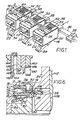
- Figure 1 is a perspective view of a portion of strip of electrical connectors, from which portion a connector has been severed;
- Figure 2 is a perspective view showing an individual connector of the strip, which has been severed therefrom and has been applied to an end of an electrical cable;
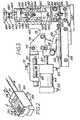
- Figure 3 is a front view shown partly in section, of apparatus for severing connectors from the strip and for applying them to cable ends;
- Figure 4 is a side view of the apparatus shown mainly in vertical section; A
- Figure 5 is a fragmentary vertical sectional view of a detail of Figure 4;
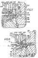
- Figure 6 is an enlarged vertical sectional side view showing a connector'application station of the apparatus and illustrating the positions of parts of the apparatus after a connector has been fed to the application station but prior to insertion of a cable end into the connector;
- Figures 7 and 8 are views similar to that of Figure 6 but showing respective successive stages, in the application of the connector to the cable end; and
- Figure 9 is a more greatly enlarged view similar to those of Figures 6 to 8 but showing the positions of the parts after the connector has been applied to the cable end.
- Electrical connectors 2 (shown in perspective view in Figures 1 and 2) for use in the telephone industry, in particular in telephone hand sets, are intended each to be applied to an end of a cable 4 which comprises four juxtaposed insulated conductors 8 (one of which is shown in Figures 7 to 9) contained within a
cable sheath 6. When aconnector 2 is to be installed on the end of a cable 4 a portion of thecable sheath 6 is removed to expose the conductors 8 although the insulation is not stripped from the conductors 8 themselves. - Each
connector 2 comprises a substantiallyrectangular housing 10 of insulating material, for example polycarbonate, thehousing 10 having a cable-receivingend 12, amating end 14, atop wall 16, abottom wall 18, andparallel side walls 20. As best seen in Figure 6, a cable-receivingcavity 22 extending inwardly from the cable-receivingend 12 towards themating end 14, comprises an enlarged portion 13 adjacent to theend 12 and which merges with aportion 24 of reduced cross-section adjacent to themating end 14. Theportion 24 is dimensioned to receive only the conductors 8, the portion 13 being dimensioned to receive the end portion of thesheath 6 of the cable 4. As best seen in Figures 6 and 7, thetop wall 16 is provided with first and secondstrain relief portions housing 10 as shown in Figures 8 and 9, to clamp thesheath 6 and the individual conductors 8 in the housing lO, to provide a secure mechanical connection between the cable 4 and theconnector 2. - Each
connector 2 also comprises fouruniplanar contact.members 30 each lodged in a through opening 31 (Figures 6 to 8) in thetop wall 16 adjacent to themating end 14 of the connector. Themembers 30 can be driven home into theopenings 31 to pierce the insulation of the conductors 8 so as to make electrical contact with the electrical conductive cores thereof. Between theopenings 31 arebarriers 33 which are so dimensioned that when thecontact members 30 have been driven home into theopenings 31, theupper edges 32 of thecontact members 30 are exposed, butadjacent contact members 30 are insulated from each other by thebarriers 33. Theedges 32 are engageable by contact spring members (not shown) in a receptacle (not shown) in which theconnector 2 is adapted to be latched in mating relationship by means of alatch arm 34 projecting from thewall 18 of thehousing 10. - Similar electrical connectors and their operation are described in detail in the specification of United States Patent No. 3,954,320 and in the specifications of other patents of which Western Electric Company Incorporated, of New York, New York State, United States of America are also the proprietors.
- The apparatus to be described is intended to apply
connectors 2 in the form of a continuous strip 1 to the ends of cables 4. As shown in Figure 1, theconnectors 2 of the strip 1 are joined by acarrier strip 36 from which theconnectors 2 extend in constantly spaced relationship lengthwise of thestrip 36, eachconnector 2 being joined to thestrip 36 by a connectinglug 38 formed integrally with thestrip 36 and with thehousing 10 of theconnector 2. - As shown in Figure 4, the apparatus has a C-
shaped frame 40 comprising abase 42 joined to an upper arm 46 (best seen in Figure 3) by aneck 48. - As shown in Figure 3, the
base 42 is mounted on theplaten 50 of a conventional bench press operated by a pedal switch (not shown). As shown in Figure 4, apress ram 184 of the bench press is directly coupled to asecond ram 164 of a ram assembly of the apparatus, so as to be indirectly coupled to afirst ram 132 of the ram assembly as described in detail below. The bench press is not otherwise shown. - Above the
base 42, (as seen in Figure 4) is aconnector application station 52 at which aconnector 2 is supported during its application to a cable 4. The strip ofconnectors 2 is fed to thestation 52 over a leftwardly (as seen in Figure 3) extendingfeed plate 54 on the upper surface of which is aconnector feed track 55 which serves to guide the connector strip 1 along theplate 54 from a rotary storage reel (not shown) to thestation 52. The strip 1 is intermittently fed during each operating cycle of the apparatus, to position the leadingconnector 2 of the strip 1 at thestation 52, by a reciprocatingfeed finger 56 connected by apivot pin 58 to ayoke 60 on apiston rod 62, thefinger 56 being biased in a clockwise (as seen in Figure 3) direction by a torsion spring (not shown) surrounding thepivot pin 58. Thepiston rod 52 extends from apneumatic cylinder 64 which is supplied with compressed air byair lines 65. Thecylinder 64 is suspended by means of amounting bracket 66 from ascrew 68 which is rotatably supported in abracket 70, thescrew 66 being axially immovable with respect thereto, the limits of the stroke of thefeed finger 56 being thereby adjustable by rotating thescrew 68. Thecylinder 64 is clamped to thebracket 70 by means of ascrew 72 which is threaded through thebracket 70 and into thebracket 66. - The
bracket 70 is secured by means of afastener 74 to aplate 76 which in turn is secured by fasteners to aplate 78 which extends leftwardly from (as seen in Figure 3), and is formed integrally with, thearm 46 of theframe 40. - A
mounting block 80 is fixed to thebase 42, acover plate 82 being secured to the upper (as seen in Figures 4 and 5) surface of theblock 80. - A
fixed shear block 84 is also secured to theblock 80 on the forward i.e. the leftward (as seen in Figure 4) face 85 thereof by fasteners 86 (Figure 3). As shown in Figure 4, afixed anvil assembly 88, formed integrally with thefeed plate 54, is mounted on thebase 42 in front of, and below theshear block 84 and comprises ananvil block 90 having arecess 92 in its upper (as seen in Figure 4) surface to provide clearance for thelatch arm 34 of the leadingconnector 2 at thestation 52, thebottom wall 18 of theconnector 2 adjacent to themating end 14 thereof being supported on anelevated surface 93 of theassembly 88. Theanvil assembly 88 further comprises ananvil front plate 94 secured to theblock 90 by fasteners 96 (Figure 3). Theplate 94 has an inwardly projecting lip 98 (Figure 4) which extends partially over therecess 92 and upon which thesurface 93 is formed. An opening 100 (Figure 3) is provided in thelip 98 to provide clearance for the latch arm.34 to permit removal of theconnector 2 from theapplication station 52 after the leadingconnector 2 has been applied to a cable end. - The leading
connector 2 of the strip 1 at theapplication station 52 is severed from thecarrier strip 36 at the conclusion of the application process (described in detail below) between movable and fixedshearing edges edge 104 is provided on a dependinglip 106 of the fixedshear block 84, theedge 102 being provided on a verticallymovable block 108 secured by fasteners 110 (as shown in Figure 4) to a slide block l12 contained in a vertically extendingslot 114 in themonting block 80, theslot 114 being covered by thecover plate 82 as shown in Figures 4 and 5. A central recess l16 (Figures 4 and 5) provided in theslide block 112 contains anactuator lever 118 fixed to astub shaft 120 journaled in theblock 80, as shown in Figure 4. Arod 122 on thesecond ram 164, mentioned above, can pass through alignedopenings plate 82 and in theslide block 112, respectively, to engage the right hand (as seen in Figure 5) end of thelever 118 so that the other end of thelever 118 rises against apin 124 which is confined with clearance in recesses in theslide block 112 and thelever 118. Thepin 124 thus raises theslide block 112 in turn to raise theblock 108, to cause themovable shearing edge 102 to move past the fixed shearingedge 104 to sever theconnector 2 at thestation 52 from the carrier strip 36 (as shown in Figure 9), by shearing through thelug 38 between theconnector 2 andstrip 36. Alug 38 which has been so sheared is shown in Figure 1. A spring 128 (Figure 4) acting between thecover plate 82 and theslide block 112 normally urges theblock 112 downwardly to an extent limited by astop screw 126 engaged by the left hand (as seen in Figure 5) end of thelever 118. - The
arm 146 of theframe 40 has a removable side cover plate 130 (Figure 3), thefirst ram 132 being slidably guided, for rectilinear vertical movement towards and away from theapplication station 52, in an opening defined by a recess in thearm 46, and thecover plate 30. Theram 132 has arecess 134 on its leftwardly (as seen in Figure 4) facing side, defining ashoulder 134 facing away from thestation 52. First andsecond tools strain relief portions ram 132 for movement with theram 132 towards theapplication station 52. The enlarged upper (as seen in Figure 4) ends of thetools recesses receiving springs tool 138 can be adjusted by means of ascrew 142 threaded through alateral extension 143 of theram 132 and bearing against the upper end of the recess in thetool 138. Thespring 140 bears against theshoulder 134 so that thetool 138 is biased against thescrew 142. Thetool 136 is retained in position against thetool 138 by acover plate 144 secured to theextension 143, and can similarly be adjusted axially by means of ascrew 145, thespring 141 acting between the upper end of the recess in thetool 136 and ashoulder 146 extending from thecover plate 144. Theplate 144 also acts as a retainer for aconnector aligning plate 152, as described below. - Working ends 148 and 150 of the
tools strain relief portions connector 2 as illustrated in Figure 9. - The leading
connector 2, at theapplication station 52, must, if it is correctly to be applied to the cable 4, be precisely aligned with thetools tools connector 2. To this end, the leadingconnector 2 of the strip 1 is first longitudinally aligned by aligning surfaces 154 (Figures 6 and 7) of theplate 152, which surfaces are moved across portions of the surface of theconnector housing 10 adjacent to its cable-receivingend 12, so that theconnector 2 is urged rightwardly (as seen in Figures 6 and 7) until themating end 14 of theconnector 2 lies against the leftwardly (as seen in Figures 6 and 7) facing surface of thelip 106 of theshear block 84. The leadingconnector 2 is then.laterally aligned with spaced apart depending legs 190 (only one of which is shown), which are disposed on either side of thetools 186 and which are formed integrally with a tool shaft 160 (described below) with which thetools 186 are also integrally formed. - The aligning
plate 152 projects towards thestation 52, beyond the working ends 148 and 150 of thetools plate 152 has a central opening 155 (see Figures 3 to 7) to provide clearance for the cable 4. Theplate 152 dwells in its lowermost position for a time whilst theother tooling ram assembly plate 152 is slidably mounted between aspacer plate 153 and the inner surface of thecover plate 144. Arecess 156 in the enlarged upper (as seen in Figures 3 and 4) end of theplate 152 contains aspring 157 which bears against the lower (as seen in Figure 3) end of arod 158 which in turn bears against the underside of theshoulder 146 of thecover plate 144. Descent of the aligningplate 152 beyond its position of Figure 4 is prevented by the interengagement of shoulders 159 (Figure 4) on theplates tools tool shaft 160 descend beyond the position in which they are shown in Figure 7, theplate 152 is permitted to dwell in its position shown in Figure 8, by virtue of the compression of thespring 157. - It will be apparent from the foregoing description that the
deforming tools first ram 132. Thetool shaft 160, however, is mounted (as shown in Figures 4 and 9) on thesecond ram 164, by means offasteners 162. Thesecond ram 164 is capable of limited overtravel relative to thefirst ram 132 after the latter has reached its bottom dead centre position, i.e. after it has carried out its working stroke. Theram 164 comprises ablock 166 which is slidably mounted in arecess 168 in the lower (as seen in Figures 4 and 9) end of theram 132. Arod 170 projects from theblock 166 through an opening in theram 132, which opening has acounterbore 172 at its upper (as seen in Figure 4) end through which counterbore therod 170 extends. A plurality ofBelleville washers 176 provided on therod 170, in thecounterbore 172, are stiffly compressed between the base of thecounterbore 172 and a collar 178 retained in position on therod 170 bylock nuts 180, engaged with screw threads (not shown) on therod 170. - The upper end of the
rod 170 has thereon anadaptor 182 by means of which therod 170 is coupled to theram 184 of the bench press. - The
insertion tools 186 on theshaft 160 project in parallel spaced relationship between the aligninglegs 188 and are dimensioned to engage theedges 132 of thecontact members 30 to drive them home into theopenings 31, as shown in Figures 8 and 9, until themembers 30 penetrate the insulation of individual conductors 8 of the cable 4 and establish electrical contact with the electrically conductive cores of the conductors 8. Theinserters 186 are dimensioned so that they do not damage thebarriers 33 of theconnector 2. - As mentioned above, the lateral alignment of the leading
connector 2 is accomplished by means of thelegs 188 which depend from the lower end of theshaft 160. Thelegs 188 are contoured and dimensioned to engageside walls 20 of theconnector 2 so as to move it laterally by a slight amount to bring thecontact members 30 into precise-alignment with theinsertion tools 186. - "Although as described above, the connector applying apparatus is mounted in a conventional bench press, it may be mounted in a semi-automatic machine (not shown) having cable feeding means and also incorporating a press similarly coupled to the
ram assembly - When the apparatus is mounted on a conventional bench press the cable is manually positioned in the leading
connector 2, the operation of the apparatus being as follows:- - The operator first inserts the end portion of a cable 4 into the cable-receiving
cavity 22 of the leadingconnector 2 of the strip 1, which was fed during the previous operating cycle of the apparatus to theapplication station 52, the cable conductor 8 extending into thecavity portion 24. The operator then closes the pedal switch of the press, to engage a single revolution clutch (not shown) so that thepress ram 184 carries out a working stroke down to its bottom dead centre position and a return stroke back to its top dead centre position. During the working stroke of theram 184, therams connector 2 at thestation 52 is first longitudinally aligned by the aligningplate 152, see Figures 7 and 8. Thereafter, theplate 152 dwells, thespring 156 is compressed, and therams deforming tools portions connector 2 as shown in Figure 8. At this stage, the cable 4 and the conductors 8 thereof are firmly held in position by thedeformed portions deforming tools first ram 132 is now brought to an abrupt halt by the engagement of astop.surface 190 on theram 132 against theplate 82, as shown in Figure 9, so that thedeforming tools - During the final portion of the working stroke of the
press ram 184, thesecond ram 164 continues to descend, after thefirst ram 132 has been stopped, see Figure 9, with accompanying compression of theBelleville washers 176. Although in Figure 9, the height of the gap 177 between the upper surface of theblock 166 and the underside of theram 122 has been exaggerated for purposes of illustration, it will be understood that the relative movement betweenrams contact members 30 from their Figure 8 to their Figure 9 positions. - As shown in Figure 9, the leading
connector 2 is finally severed from thecarrier strip 36 by the shearing edges 102 and 103, as a result of the actuation of thelever 118 by therod 122 on theram block 166. - As the
press ram 184 carries out its return stroke the parts of the apparatus are returned to their initial positions and thefeed finger 56 is actuated to advance the strip 1 to position the next followingconnector 2 at theapplication station 52. - In the interest of simplifying the apparatus, the tools for deforming the strain relief portions of the connector housing and the tools for driving home the
contact members 30 may all be coupled to a single ram of the apparatus so as to carry out co-terminous working strokes.
Claims (8)
Applications Claiming Priority (2)
| Application Number | Priority Date | Filing Date | Title |
|---|---|---|---|
| US05/895,556 US4178675A (en) | 1978-04-12 | 1978-04-12 | Applicator for telephone connectors |
| US895556 | 1978-04-12 |
Publications (3)
| Publication Number | Publication Date |
|---|---|
| EP0004779A2 true EP0004779A2 (en) | 1979-10-17 |
| EP0004779A3 EP0004779A3 (en) | 1979-10-31 |
| EP0004779B1 EP0004779B1 (en) | 1981-02-18 |
Family
ID=25404685
Family Applications (1)
| Application Number | Title | Priority Date | Filing Date |
|---|---|---|---|
| EP79300558A Expired EP0004779B1 (en) | 1978-04-12 | 1979-04-04 | Apparatus for applying electrical connectors to cables |
Country Status (9)
| Country | Link |
|---|---|
| US (1) | US4178675A (en) |
| EP (1) | EP0004779B1 (en) |
| JP (1) | JPS54137687A (en) |
| AU (1) | AU520104B2 (en) |
| BR (1) | BR7902277A (en) |
| CA (1) | CA1086032A (en) |
| DE (1) | DE2960180D1 (en) |
| ES (1) | ES479493A1 (en) |
| MX (1) | MX144841A (en) |
Cited By (1)
| Publication number | Priority date | Publication date | Assignee | Title |
|---|---|---|---|---|
| EP0104874A2 (en) * | 1982-09-24 | 1984-04-04 | Molex Incorporated | Electrical harness fabrication method and apparatus |
Families Citing this family (12)
| Publication number | Priority date | Publication date | Assignee | Title |
|---|---|---|---|---|
| US4258469A (en) * | 1979-09-10 | 1981-03-31 | Salvesen William R | Apparatus and method for installing electrical connectors |
| US4536939A (en) * | 1982-11-19 | 1985-08-27 | At&T Technologies, Inc. | Tool for terminating telephone cordage with modular plugs |
| JPS59134281U (en) * | 1983-02-26 | 1984-09-07 | 東洋端子株式会社 | connector housing |
| JPS59134282U (en) * | 1983-02-26 | 1984-09-07 | 東洋端子株式会社 | connector housing |
| US4667398A (en) * | 1985-01-22 | 1987-05-26 | Amp Incorporated | Improved applicator tooling for certain electrical connectors |
| GB8708801D0 (en) * | 1987-04-13 | 1987-05-20 | Amp Gmbh | Wiring head |
| JPH01137091U (en) * | 1988-03-12 | 1989-09-19 | ||
| US5005284A (en) * | 1988-11-18 | 1991-04-09 | At&T Bell Laboratories | Method of assembling terminals with modular plug |
| JPH043656U (en) * | 1990-04-25 | 1992-01-14 | ||
| US5410803A (en) * | 1993-12-16 | 1995-05-02 | The Whitaker Corporation | Feed mechanism in a tool for terminating ribbon cable to a connector |
| US6367148B1 (en) | 1997-06-25 | 2002-04-09 | Panduit Corp. | Terminal applicator movement control mechanism |
| WO2007144752A2 (en) * | 2006-06-16 | 2007-12-21 | Schleuniger Holding Ag | Clamping apparatus for a crimping machine and method for producing a crimped connection with a crimping machine and the clamping apparatus according to the invention |
Citations (6)
| Publication number | Priority date | Publication date | Assignee | Title |
|---|---|---|---|---|
| FR1544445A (en) * | 1966-11-16 | 1968-10-31 | Amp Inc | Method and apparatus for crimping an insulating sleeve onto a connector |
| US3550239A (en) * | 1968-09-13 | 1970-12-29 | Amp Inc | Terminal applicator having means for separating dies |
| US3835445A (en) * | 1972-12-04 | 1974-09-10 | Western Electric Co | Electrical connecting devices for terminating cords and methods of assembling the devices to cords |
| US3839787A (en) * | 1973-03-30 | 1974-10-08 | Western Electric Co | Assembling electrical components |
| US3860316A (en) * | 1973-07-06 | 1975-01-14 | Western Electric Co | Electrical connecting devices for terminating cords and methods of assembling the devices to cords |
| US4114253A (en) * | 1977-05-11 | 1978-09-19 | Amp Incorporated | Application for terminals in strip form |
Family Cites Families (6)
| Publication number | Priority date | Publication date | Assignee | Title |
|---|---|---|---|---|
| NL135645C (en) * | 1964-07-30 | |||
| NL145405B (en) * | 1969-03-28 | 1975-03-17 | Amp Inc | DEVICE FOR SHRINKING A PRACTICAL U-SHAPED TUBE PART OF AN ELECTRICAL CONNECTOR AT ONE END OF A WIRE. |
| US3668764A (en) * | 1970-12-24 | 1972-06-13 | Artos Engineering Co | Automatic terminal applicator for insulated non-metallic ignition type wires |
| US3911717A (en) * | 1974-01-18 | 1975-10-14 | Itt | Terminal applicator apparatus |
| US4031613A (en) * | 1976-03-04 | 1977-06-28 | Amp Incorporated | Closed barrel terminal applicator |
| US4040180A (en) * | 1976-06-15 | 1977-08-09 | Amp Incorporated | Wire cone assembly |
-
1978
- 1978-04-12 US US05/895,556 patent/US4178675A/en not_active Expired - Lifetime
-
1979
- 1979-03-13 CA CA323,348A patent/CA1086032A/en not_active Expired
- 1979-03-13 AU AU45126/79A patent/AU520104B2/en not_active Expired
- 1979-04-04 EP EP79300558A patent/EP0004779B1/en not_active Expired
- 1979-04-04 DE DE7979300558T patent/DE2960180D1/en not_active Expired
- 1979-04-10 ES ES479493A patent/ES479493A1/en not_active Expired
- 1979-04-10 MX MX177255A patent/MX144841A/en unknown
- 1979-04-11 JP JP4411479A patent/JPS54137687A/en active Granted
- 1979-04-11 BR BR7902277A patent/BR7902277A/en unknown
Patent Citations (6)
| Publication number | Priority date | Publication date | Assignee | Title |
|---|---|---|---|---|
| FR1544445A (en) * | 1966-11-16 | 1968-10-31 | Amp Inc | Method and apparatus for crimping an insulating sleeve onto a connector |
| US3550239A (en) * | 1968-09-13 | 1970-12-29 | Amp Inc | Terminal applicator having means for separating dies |
| US3835445A (en) * | 1972-12-04 | 1974-09-10 | Western Electric Co | Electrical connecting devices for terminating cords and methods of assembling the devices to cords |
| US3839787A (en) * | 1973-03-30 | 1974-10-08 | Western Electric Co | Assembling electrical components |
| US3860316A (en) * | 1973-07-06 | 1975-01-14 | Western Electric Co | Electrical connecting devices for terminating cords and methods of assembling the devices to cords |
| US4114253A (en) * | 1977-05-11 | 1978-09-19 | Amp Incorporated | Application for terminals in strip form |
Cited By (2)
| Publication number | Priority date | Publication date | Assignee | Title |
|---|---|---|---|---|
| EP0104874A2 (en) * | 1982-09-24 | 1984-04-04 | Molex Incorporated | Electrical harness fabrication method and apparatus |
| EP0104874A3 (en) * | 1982-09-24 | 1984-05-09 | Molex Incorporated | Electrical harness fabrication method and apparatus |
Also Published As
| Publication number | Publication date |
|---|---|
| DE2960180D1 (en) | 1981-04-02 |
| EP0004779A3 (en) | 1979-10-31 |
| EP0004779B1 (en) | 1981-02-18 |
| US4178675A (en) | 1979-12-18 |
| AU4512679A (en) | 1979-10-18 |
| JPS54137687A (en) | 1979-10-25 |
| ES479493A1 (en) | 1980-01-01 |
| JPS6135669B2 (en) | 1986-08-14 |
| MX144841A (en) | 1981-11-24 |
| CA1086032A (en) | 1980-09-23 |
| BR7902277A (en) | 1979-12-11 |
| AU520104B2 (en) | 1982-01-14 |
Similar Documents
| Publication | Publication Date | Title |
|---|---|---|
| EP0034433B1 (en) | An electrical connector, a method of gang terminating electrical conductors and apparatus for carrying out the method | |
| EP0000428B1 (en) | Method of, and apparatus for, making electrical harnesses | |
| EP0004779B1 (en) | Apparatus for applying electrical connectors to cables | |
| US3570100A (en) | Insulation stripping attachment for electrical connector crimping press and connector crimping press having insulation stripping means | |
| US4139937A (en) | Apparatus for applying a tubular insulating housing to an electrical connector secured to a wire | |
| US3484922A (en) | Crimping apparatus for coaxial terminals in strip form | |
| CA1280875C (en) | Terminal strip applicator | |
| US4979291A (en) | Apparatus and method of terminating a wire to a two part insulated terminal | |
| EP0177205A2 (en) | Combination tool | |
| US4074424A (en) | Crimping and wire lead insertion machine | |
| US5174022A (en) | Apparatus and method of terminating a wire to a two part insulated terminal | |
| US3479718A (en) | Stripping and crimping apparatus | |
| US4516309A (en) | Apparatus for assembling an electrical connector to a cable | |
| US4332083A (en) | Terminating apparatus for flat cable | |
| US3420086A (en) | Hand tool for crimping terminals | |
| GB1213450A (en) | Apparatus for crimping electrical connectors to wires | |
| US4001931A (en) | Wire termination method | |
| US4598570A (en) | Apparatus for crimping electric terminals | |
| CA1206328A (en) | Electrical harness manufacturing method and apparatus | |
| EP0375458A1 (en) | The stripping and terminating of conductors in multi core cables | |
| US5457876A (en) | Conductor guide mechanism in a tool for terminating conductors of a cable to a connector | |
| GB1103617A (en) | Electrical connector crimping apparatus | |
| US2668950A (en) | Apparatus for applying terminals to electrical conductor wires | |
| US3541654A (en) | Stripper-crimper device | |
| US3673847A (en) | Round socket applicator |
Legal Events
| Date | Code | Title | Description |
|---|---|---|---|
| PUAI | Public reference made under article 153(3) epc to a published international application that has entered the european phase |
Free format text: ORIGINAL CODE: 0009012 |
|
| PUAL | Search report despatched |
Free format text: ORIGINAL CODE: 0009013 |
|
| AK | Designated contracting states |
Designated state(s): BE DE FR GB IT NL SE |
|
| AK | Designated contracting states |
Designated state(s): BE DE FR GB IT NL SE |
|
| 17P | Request for examination filed | ||
| ITF | It: translation for a ep patent filed |
Owner name: BARZANO' E ZANARDO MILANO S.P.A. |
|
| GRAA | (expected) grant |
Free format text: ORIGINAL CODE: 0009210 |
|
| AK | Designated contracting states |
Designated state(s): BE DE FR GB IT NL SE |
|
| REF | Corresponds to: |
Ref document number: 2960180 Country of ref document: DE Date of ref document: 19810402 |
|
| ITTA | It: last paid annual fee | ||
| REG | Reference to a national code |
Ref country code: GB Ref legal event code: 732E |
|
| EAL | Se: european patent in force in sweden |
Ref document number: 79300558.8 |
|
| PGFP | Annual fee paid to national office [announced via postgrant information from national office to epo] |
Ref country code: SE Payment date: 19950322 Year of fee payment: 17 |
|
| PGFP | Annual fee paid to national office [announced via postgrant information from national office to epo] |
Ref country code: NL Payment date: 19950430 Year of fee payment: 17 |
|
| PGFP | Annual fee paid to national office [announced via postgrant information from national office to epo] |
Ref country code: BE Payment date: 19950511 Year of fee payment: 17 |
|
| PG25 | Lapsed in a contracting state [announced via postgrant information from national office to epo] |
Ref country code: SE Effective date: 19960405 |
|
| PG25 | Lapsed in a contracting state [announced via postgrant information from national office to epo] |
Ref country code: BE Effective date: 19960430 |
|
| BERE | Be: lapsed |
Owner name: AMP INC. (UNE SOC. DE PENNSYLVANIE) Effective date: 19960430 |
|
| PG25 | Lapsed in a contracting state [announced via postgrant information from national office to epo] |
Ref country code: NL Effective date: 19961101 |
|
| NLV4 | Nl: lapsed or anulled due to non-payment of the annual fee |
Effective date: 19961101 |
|
| EUG | Se: european patent has lapsed |
Ref document number: 79300558.8 |
|
| PGFP | Annual fee paid to national office [announced via postgrant information from national office to epo] |
Ref country code: GB Payment date: 19980312 Year of fee payment: 20 |
|
| PGFP | Annual fee paid to national office [announced via postgrant information from national office to epo] |
Ref country code: FR Payment date: 19980408 Year of fee payment: 20 |
|
| PGFP | Annual fee paid to national office [announced via postgrant information from national office to epo] |
Ref country code: DE Payment date: 19980429 Year of fee payment: 20 |
|
| PG25 | Lapsed in a contracting state [announced via postgrant information from national office to epo] |
Ref country code: GB Free format text: LAPSE BECAUSE OF NON-PAYMENT OF DUE FEES Effective date: 19990403 |
|
| REG | Reference to a national code |
Ref country code: GB Ref legal event code: PE20 Effective date: 19990403 |
|
| PLBE | No opposition filed within time limit |
Free format text: ORIGINAL CODE: 0009261 |
|
| STAA | Information on the status of an ep patent application or granted ep patent |
Free format text: STATUS: NO OPPOSITION FILED WITHIN TIME LIMIT |