EP0004756B1 - Rotary drum and method of mixing, drying, cooling, heating or calcining solid particles - Google Patents
Rotary drum and method of mixing, drying, cooling, heating or calcining solid particles Download PDFInfo
- Publication number
- EP0004756B1 EP0004756B1 EP79300527A EP79300527A EP0004756B1 EP 0004756 B1 EP0004756 B1 EP 0004756B1 EP 79300527 A EP79300527 A EP 79300527A EP 79300527 A EP79300527 A EP 79300527A EP 0004756 B1 EP0004756 B1 EP 0004756B1
- Authority
- EP
- European Patent Office
- Prior art keywords
- particles
- drum
- blocks
- angle
- kiln
- Prior art date
- Legal status (The legal status is an assumption and is not a legal conclusion. Google has not performed a legal analysis and makes no representation as to the accuracy of the status listed.)
- Expired
Links
- 239000002245 particle Substances 0.000 title claims description 74
- 238000001354 calcination Methods 0.000 title claims description 20
- 239000007787 solid Substances 0.000 title claims description 17
- 238000002156 mixing Methods 0.000 title claims description 10
- 238000010438 heat treatment Methods 0.000 title claims description 8
- 238000000034 method Methods 0.000 title claims description 8
- 238000001035 drying Methods 0.000 title claims description 7
- 238000001816 cooling Methods 0.000 title claims description 6
- 239000000463 material Substances 0.000 claims description 34
- 235000019738 Limestone Nutrition 0.000 claims description 26
- 239000006028 limestone Substances 0.000 claims description 25
- 230000010006 flight Effects 0.000 claims description 6
- CURLTUGMZLYLDI-UHFFFAOYSA-N Carbon dioxide Chemical compound O=C=O CURLTUGMZLYLDI-UHFFFAOYSA-N 0.000 description 13
- 235000008733 Citrus aurantifolia Nutrition 0.000 description 11
- 235000011941 Tilia x europaea Nutrition 0.000 description 11
- 229910002092 carbon dioxide Inorganic materials 0.000 description 11
- 239000000428 dust Substances 0.000 description 11
- 239000004571 lime Substances 0.000 description 11
- 239000000047 product Substances 0.000 description 11
- ZLNQQNXFFQJAID-UHFFFAOYSA-L magnesium carbonate Chemical compound [Mg+2].[O-]C([O-])=O ZLNQQNXFFQJAID-UHFFFAOYSA-L 0.000 description 8
- 239000001095 magnesium carbonate Substances 0.000 description 8
- 229910000021 magnesium carbonate Inorganic materials 0.000 description 8
- 235000014380 magnesium carbonate Nutrition 0.000 description 8
- 238000004519 manufacturing process Methods 0.000 description 8
- 230000015572 biosynthetic process Effects 0.000 description 7
- VTYYLEPIZMXCLO-UHFFFAOYSA-L Calcium carbonate Chemical compound [Ca+2].[O-]C([O-])=O VTYYLEPIZMXCLO-UHFFFAOYSA-L 0.000 description 6
- 239000001569 carbon dioxide Substances 0.000 description 6
- 239000010459 dolomite Substances 0.000 description 5
- 229910000514 dolomite Inorganic materials 0.000 description 5
- 239000007789 gas Substances 0.000 description 5
- 239000011819 refractory material Substances 0.000 description 5
- VYPSYNLAJGMNEJ-UHFFFAOYSA-N Silicium dioxide Chemical compound O=[Si]=O VYPSYNLAJGMNEJ-UHFFFAOYSA-N 0.000 description 4
- 229910000019 calcium carbonate Inorganic materials 0.000 description 4
- 238000011065 in-situ storage Methods 0.000 description 4
- 230000008569 process Effects 0.000 description 4
- CPLXHLVBOLITMK-UHFFFAOYSA-N Magnesium oxide Chemical compound [Mg]=O CPLXHLVBOLITMK-UHFFFAOYSA-N 0.000 description 3
- 230000001419 dependent effect Effects 0.000 description 3
- 239000003337 fertilizer Substances 0.000 description 3
- 239000010419 fine particle Substances 0.000 description 3
- 230000004907 flux Effects 0.000 description 3
- -1 gravel Substances 0.000 description 3
- 239000004576 sand Substances 0.000 description 3
- 239000004575 stone Substances 0.000 description 3
- 238000011144 upstream manufacturing Methods 0.000 description 3
- OYPRJOBELJOOCE-UHFFFAOYSA-N Calcium Chemical compound [Ca] OYPRJOBELJOOCE-UHFFFAOYSA-N 0.000 description 2
- CWYNVVGOOAEACU-UHFFFAOYSA-N Fe2+ Chemical compound [Fe+2] CWYNVVGOOAEACU-UHFFFAOYSA-N 0.000 description 2
- 238000004873 anchoring Methods 0.000 description 2
- BRPQOXSCLDDYGP-UHFFFAOYSA-N calcium oxide Chemical compound [O-2].[Ca+2] BRPQOXSCLDDYGP-UHFFFAOYSA-N 0.000 description 2
- 239000000292 calcium oxide Substances 0.000 description 2
- ODINCKMPIJJUCX-UHFFFAOYSA-N calcium oxide Inorganic materials [Ca]=O ODINCKMPIJJUCX-UHFFFAOYSA-N 0.000 description 2
- 239000003054 catalyst Substances 0.000 description 2
- 210000003734 kidney Anatomy 0.000 description 2
- 239000000395 magnesium oxide Substances 0.000 description 2
- 229910052751 metal Inorganic materials 0.000 description 2
- 239000002184 metal Substances 0.000 description 2
- 239000008188 pellet Substances 0.000 description 2
- 239000000126 substance Substances 0.000 description 2
- 229910021532 Calcite Inorganic materials 0.000 description 1
- PNEYBMLMFCGWSK-UHFFFAOYSA-N aluminium oxide Inorganic materials [O-2].[O-2].[O-2].[Al+3].[Al+3] PNEYBMLMFCGWSK-UHFFFAOYSA-N 0.000 description 1
- 238000005452 bending Methods 0.000 description 1
- 238000005219 brazing Methods 0.000 description 1
- 239000003245 coal Substances 0.000 description 1
- 239000011248 coating agent Substances 0.000 description 1
- 238000000576 coating method Methods 0.000 description 1
- 239000000571 coke Substances 0.000 description 1
- 239000000567 combustion gas Substances 0.000 description 1
- 238000010276 construction Methods 0.000 description 1
- 239000012467 final product Substances 0.000 description 1
- 230000006872 improvement Effects 0.000 description 1
- 230000002452 interceptive effect Effects 0.000 description 1
- AXZKOIWUVFPNLO-UHFFFAOYSA-N magnesium;oxygen(2-) Chemical compound [O-2].[Mg+2] AXZKOIWUVFPNLO-UHFFFAOYSA-N 0.000 description 1
- 230000004048 modification Effects 0.000 description 1
- 238000012986 modification Methods 0.000 description 1
- 230000002265 prevention Effects 0.000 description 1
- 150000003839 salts Chemical class 0.000 description 1
- 239000000377 silicon dioxide Substances 0.000 description 1
- 239000002699 waste material Substances 0.000 description 1
- 238000003466 welding Methods 0.000 description 1
Images

Classifications
-
- F—MECHANICAL ENGINEERING; LIGHTING; HEATING; WEAPONS; BLASTING
- F27—FURNACES; KILNS; OVENS; RETORTS
- F27B—FURNACES, KILNS, OVENS OR RETORTS IN GENERAL; OPEN SINTERING OR LIKE APPARATUS
- F27B7/00—Rotary-drum furnaces, i.e. horizontal or slightly inclined
- F27B7/14—Rotary-drum furnaces, i.e. horizontal or slightly inclined with means for agitating or moving the charge
- F27B7/16—Rotary-drum furnaces, i.e. horizontal or slightly inclined with means for agitating or moving the charge the means being fixed relatively to the drum, e.g. composite means
- F27B7/161—Rotary-drum furnaces, i.e. horizontal or slightly inclined with means for agitating or moving the charge the means being fixed relatively to the drum, e.g. composite means the means comprising projections jutting out from the wall
- F27B7/162—Rotary-drum furnaces, i.e. horizontal or slightly inclined with means for agitating or moving the charge the means being fixed relatively to the drum, e.g. composite means the means comprising projections jutting out from the wall the projections consisting of separate lifting elements, e.g. lifting shovels
Definitions
- This invention generally relates to an apparatus for mixing, drying, cooling, heating or calcining solid particles comprising mixer blocks in a generally horizontal rotary kiln whereby more efficient and uniform calcination of fluxstone is achieved while the production of fines or dust is reduced to a minimum.
- Solid particles such as gravel, sand, stone, cementitious particles, limestone, dolomite, dolomitic limestone, magnesite, fertilizers, catalysts, and the like are frequently mixed, heated, cooled, dried or calcined in a generally horizontal rotating drum or kiln; see for example U.S. Patents 649999; 1544504; 3408969 and also 3787034.
- the bed of particles in the drum is carried upwardly by friction a distance along the interior periphery of the drum wall.
- the weight of the bed of particles overcomes friction, the particles slide downwardly to the bottom of the drum. This process is repeated as the drum continues to rotate.
- the fines and dust particles coat the larger particles thereby interfering with the mixing, drying and calcination processes. Then, too, the dust particles are so fine that many are exhausted to the atmosphere with the exhaust gases, thereby creating a hazard to the environment. It is accordingly necessary to use apparatus to collect the dust to prevent it from being passed to the atmosphere. Operational costs are thereby increased.
- the dust is often a waste product and cannot be used. Fine particles often must be separated from the large particles of the material in the kiln.
- an apparatus for mixing, drying, cooling, heating or calcining solid particles comprising a rotatable drum containing particles to be treated and having a generally cylindrical outer metallic shell (11), a feed end (14) and a discharge end (15), means for charging the solid particles into the feed end of the drum, means for removing the solid particles from the discharge end of the drum, a plurality of mixer blocks (20) mounted on the inner surface of the drum, the blocks each having a leading (22) and a trailing (23) surface (with respect to the direction rotation), a base surface (21) and end surfaces (21 a, 21 b), said leading and trailing surface converging in a radially inward direction so that at least the radially inward part of the block has a substantially triangular radial cross-section and is defined by said leading and trailing surfaces and a plane through the intersection lines of said leading and trailing surfaces with the base surface (21) of the block (figure 1) or with other side surfaces (28, 29)
- the generally triangular cross-sectional shape provided by the base surface and the converging leading and trailing side surfaces defines an upper portion of the mixer block which in the modified form has a generally polygonal cross-section having a quadrilateral lower portion which also has a base surface and two converging side surfaces extending upwardly from the base surface of the lower portion.
- the upper triangular portion is an extension of the lower quadrilateral portion with the two portions being related so that the base surface of the upper portion is common with a top surface of the lower portion and with the side surfaces of the upper portion extending upwardly from the side surfaces of the lower portion to form a top surface of the block which because of the shape of the upper and lower portions thereof has end surfaces of polygonal form.
- the height of the mixer blocks in all embodiments is preferably at least equal to one-third the depth of the bed of solid particles in the drum and is especially adapted for use in a rotary kiln to calcine fluxes, for example limestone, magnesite and the like.
- the mixer blocks are preferably laid atop the hot face of the refractory lining, but can be laid-up against the inner metallic wall of the kiln.
- the mixer blocks may be prefabricated and laid as refractory blocks or can be cast in situ.
- each of the mixer blocks passes consecutively through the bed of solid particles in the kiln, thereby mixing the particles and preventing the formation of a "kidney". A portion of the particles is carried a distance along the periphery of the kiln wall.
- the side surfaces of the mixer blocks (notably the side surfaces of the triangular section), have substantially the same slope as the material in the kiln, the particles are lifted a distance so that they roll or pass downwardly in layers over themselves to the bottom of the kiln. Because the particles do not fall to the bottom of the kiln, breakage of the particles is virtually eliminated. Hence, the formation of fines and dust is substantially reduced if not completely eliminated. In the process, the particles are exposed to the hot gases in the kiln resulting in a uniformly calcined product which is substantially free of fines and dust.
- the mixer block used in the rotary drum of the invention is generally triangular in cross-section.
- the block can be made of any material, such as ferrous or non-ferrous metals or refractory material so long as the material will withstand the environment in which it is to be used.
- the block can be made by bending a metallic plate into the desired shape or can be made by welding or brazing metallic plates together with a form which is generally triangular in cross-section.
- the block may also be preformed using refractory material or may be cast in situ using castable refractory materials.
- the mixer block as shown in FIGURE 1 is made from a refractory or coated with a refractory, for example magnesia, alumina, alumina-silica and the like, which desirably is the same refractory composition from which the refractory blocks comprising the refractory lining are made.
- the mixer block 20 has a generally rectangular base surface 21 and two end surfaces 21 a and 21 b, and a top surface 24.
- the base surface 21 is generally rectangular and may be flat or slightly convex as shown in FIGURE 1. If it is convex it has a radius of curvature equal to the radius of curvature of the interior wall of the rotary drum or the hot face of the refractory lining in the kiln. The curvature is usually so slight that the surface may be considered to be flat.
- the mixer block is laid-up contiguous with the periphery of the interior of the drum or the hot face of the refractory lining.
- the side surfaces and end surfaces extend inwardly into the interior of the drum a distance at least equal to one-third the depth of the particles in the bottom of the drum.
- a converging side surface 22 comes initially into contact with the particles.
- This first converging side surface 22 is hereinafter referred to as the leading surface.
- the second converging surface 23 is hereinafter referred to as the trailing surface. While we have said that the height of the mixer block is at least equal to one-third the depth of the particles in the drum, the mixer block may be large enough to extend beyond the surface of the particles. However, it is preferred to use a mixer block which is at least one-third the depth of the particles, but does not exceed about 90% of the depth of the particles.
- the leading surface 22 is the first surface of the mixer block to contact the particles as the drum rotates.
- the included angle "a" formed by the intersection of the leading surface 22 and the base surface 21 should be about the same angle as the angle of repose of the material in the drum. However, the included angle can be within plus 10° to minus 10° of the angle of repose of the material in the drum. It is preferred, furthermore, to use an included angle which is within 5° or minus 5° of the angle of repose of the material.
- the angle of repose or rest angle of a material is the maximum angle with a horizontal plane at which loose material will stand on a horizontal base without sliding. It is often between 30° and 35°. In the case of limestone it is about 38°.
- the material When the drum rotates, the material is lifted upwardly by the leading surface 22 of the mixer block 20 for a distance along the periphery of the interior surface in the drum. Because the slope of the converging surfaces is approximately equal to the angle of repose of the material, the particles roll or pass downwardly in layers over themselves to the bottom of the drum. Since the particles do not fall downwardly, undue breakage of the particles is eliminated and the production of fines and dust is minimized.
- angle "b” formed by the intersection of the trailing surface 23 and the base surface 21 is not as important as angle “a” and need not necessarily be equal to angle “a” but it is preferred that angle “b” also be within plus 10° to minus 10° and preferable plus 5° to minus 5° of the angle of repose of the material in the drum.
- mixer block we will describe its use in a rotary kiln suitable for calcining flux material, such as limestone, dolomite, dolomitic limestone, magnesite, and the like although the invention is not limited to such use.
- flux material such as limestone, dolomite, dolomitic limestone, magnesite, and the like.
- calcination is defined as "(1) oxide formation by heating oxy salts e.g. calcium oxide from calcite.
- the rotary kiln 10 includes an outer metallic shell 11 and a refractory lining 12 contiguous with the interior surface 13 of the shell 11.
- the kiln 10 has a feed or upstream end 14 and a discharge or downstream end 15.
- a burner 16 is provided at the end 15 of the kiln whereby hot gases are produced in the kiln 10. The hot gases flow countercurrently to the passage of the material 17 in the kiln 10.
- the refractory lining 12 extends the length of the kiln 10 and includes a plurality of refractory blocks 18.
- a plurality of mixer blocks 20 are laid up contiguous with the hot face of the refractory blocks at selected locations as shown along the length of the kiln 10. While only one mixer block 20 is shown at each location, a plurality of mixer blocks 20 (dependent upon the size of the kiln and hereinafter referred to as a set) are evenly spaced around the periphery of the refractory lining.
- Each set comprises at least four mixer blocks 20.
- a set can be comprised of any number of blocks from at least, for example, four up to eight or ten mixer blocks spaced more or less evenly around the periphery of the inner wall of the kiln.
- the number of sets used in each kiln is dependent upon the length of the kiln.
- Each set of mixer blocks may be rotationally offset a desired distance from the adjacent set peripherally around the kiln. In the illustrated embodiment the sets of mixer blocks are rotationally offset 20°; however, the angle can be greater or lesser than 20°.
- Each mixer block 20 is generally triangular in cross-section as shown in FIGURES 1 and 3. Of course it is possible to use sets of mixer blocks which form a continuous longitudinal line the length of the kiln rather than being offset as described above.
- the mixer block 20 has a base surface 21, two end surfaces 21 a and 21 b and two converging side surfaces 22 and 23 which terminate in a top surface 24 as shown.
- the converging side surfaces 22 and 23 if extended would meet to form a sharp edge which is difficult to manufacture and which is subject to early breakage.
- the mixer block 20 is preferably made with the truncated surface 24.
- the base surface 21 can be a generally flat rectangular surface; it may also be convex to conform to the curvature of the refractory lining.
- the base surface is fitted to the refractory lining by placement in a recess 25a formed in the refractory blocks 18.
- the converging side surface 22 is the first surface of the mixer block which contacts the particles of the material as the kiln rotates in a clockwise direction and is the leading surface.
- the second converging side surface 23 is the trailing surface.
- the included angle "a" formed by the juncture or intersection of the leading surface 22 and the base surface 21 may be plus 10° or minus 10° and preferably plus 5° or minus 5° of the angle of repose of the material being calcined.
- the included angle "b" formed by the juncture or intersection of the trailing surface 23 and the base surface 21 is also preferably plus 10° or minus 10° and preferably plus 5° or minus 5° of the angle of repose of the material being calcined.
- the included angles "a” and “b” can be determined by passing a flat plane perpendicular to a radius of the kiln through the intersections of the converging side surfaces and the base surface.
- the angle formed by the intersection of the flat plane and the converging side surfaces forms the included angles "a” and "b". While the included angles "a” and “b” are not necessarily equal, it is preferred that the angles are equal or nearly so.
- the mixer block 20 can be a preformed shape or can be cast in situ. If a preformed shape is used, the refractory blocks 18 in the refractory lining 12 are installed either recessed as previously noted at the locations desired as shown at 25a or they can be made with the base surface having a radius of curvature equal to the radius of curvature of the refractory blocks 18. If cast in situ, the bottom surface 21 will be convex and have the same radius of curvature as the hot face of the refractory lining 12.
- the mixer block 20 can be firmly held in place by conventional means such as bolts (shown in phantom in FIGURES 3 and 4) welded to the interior surface of the metallic shell 11 and extending radially inwardly a predetermined distance from the shell 11 to thereby provide an anchor to retain the mixer blocks in place.
- bolts shown in phantom in FIGURES 3 and 4
- Such means requires providing the necessary bores in the refractory blocks used in the refractory lining.
- the bores are filled with the same refractory as the refractory lining and mixer block 20.
- One such means of anchoring a refractory material is described in U.S. Patent 3,445,099 which describes a means for fastening castable refractory linings in a rotary kiln.
- Other suitable anchoring arrangements can also be used as will be apparent to those skilled in the art.
- the mixer block as being solid; however, to conserve material and to reduce its weight, voids can be formed in the block by means well known in the art.
- cardboard tubes of a desired size may be used and the refractory material formed around the tubes.
- FIGURE 4 shows the position of the material as kiln 10 is rotating in a clockwise direction.
- FIGURE 5 shows another embodiment of the mixer block 20.
- the mixer block 20 has a quadrilateral lower portion 25 and a generally triangularly shaped upper portion 26.
- the lower portion 25 has a convex bottom surface 27 which has the same radius of curvature as the interior 13 of the shell 11, and is laid contiguous with the interior surface 13 of the shell 11. More specifically, the lower portion 25 has two generally rectangular side surfaces 28 and 29 which are contiguous with adjacent refractory blocks 18 when fitted to the refractory lining 12.
- the generally triangular upper portion 26 is the same shape as described previously and has the same end and converging side surfaces; therefore we have used identical numbers for identification of these end and converging side surfaces.
- the included angles "a” and “b” can be determined by drawing a vertical line downwardly from the surface 24 to the inner wall of the drum. A plane perpendicular to the vertical line is then drawn through the intersections of the side surfaces 28 and 22 and 29 and 23 respectively.
- the angles "a” and “b” formed by such perpendicular plane and the side surfaces 22 and 23, respectively, are taken as the included angles "a” and "b” of the triangular upper portion.
- the perpendicular plane is the base surface of the upper portion 26 and the top surface of the lower portion 25.
- the included angles "a” and “b” can be as much as plus 10° or minus 10° but are preferably plus 5° and minus 5° of the angle of repose of the material in the kiln. In the case of limestone, the angle of repose is 38° therefore the included angles "a” and “b” can be between 48° and 28° and preferably between 43° and 33° (the showing applying equally to the other embodiments of the mixer blocks).
- the end surfaces 21 a and 21 b can be substantially half-conical in shape.
- the half-conical shape on the downstream end of the block which may be either 21 a or 21 b provides easy flow of the hot combustion gases passing upstream in the kiln, around the block and also aids in the prevention of scale formation on such surface in kilns fired with coal.
- the half-conical shape on the upstream end surface of the block aids in the downstream flow of the solid particles around the block.
- the blocks may be made with one or both or either of the end surfaces half-conical in shape, however it is preferred that at least the downstream end surfaces have a half-conical shape.
- FIGURE 7 shows the use of a plurality of flights 22a and 22b formed on the leading 22 and trailing 23 surfaces of the mixer block 20.
- Each test run was made by charging limestone having a particle size in the range of 1/4 inch by 6 mesh (U.S.S.) (6.35 mm x 3.36 mm) to the kiln at a feed rate of 20 pounds (9.07 kg.) per minute. The kiln was rotated at 1.25 rpm. All the test runs were made at room temperature. The product produced in each test run was screened. The results are shown below:
- test Nos. 1 and 2 It can be seen from the above test Nos. 1 and 2 that the use of conventional lifters in a kiln results in considerable breakage of the particles as they pass through the kiln whereas there is substantially no breakage of particles when using the mixer blocks of the invention as shown in test No. 3.
- the virtual absence of very fine particles in test Nos. 1 and 2 indicates that a portion of the particles have been reduced to a size which is so fine that they can be swept out of the kiln in the exhaust gases. Such fine particles are not produced when using the mixer blocks in the rotary drum of the invention as can be seen in test No. 3.
- the No. 1 Batch of limestone was fed at a rate of 20.6 pounds (9.344 kg) per minute into the 30 inch (0.762 m) diameter rotary kiln having a refractory lining which was devoid of any lifters or mixer blocks.
- the depth of the bed in the kiln was 3 inches (76.2 mm).
- the kiln was operated at a speed of 1.25 revolutions per minute.
- the temperature in the kiln was 1941°F (1061 °C).
- 12.5 pounds (5.67 kg) of lime per minute were produced.
- the calcined limestone or lime was screened and analyzed for C O2 content. The size consist and carbon dioxide (C0 2 ) content are shown below:
- the No. 2 Batch of limestone was fed into the same 30 inch (0.762 m) diameter kiln, however the kiln was provided with three sets of mixer blocks.
- the depth of the bed in the kiln was 4 inches (101.6 mm).
- the mixer blocks were 24 inches (0.609 m) in length and the height of the triangular portions was 2-7/8 inches (73.025 mm).
- the mixer blocks were spaced 12 inches (0.304 m) apart along the length of the kiln and were 60° apart around the periphery of the interior of the kiln. Each set of mixer blocks was rotatably displaced 20° from the preceding set of mixer blocks. The limestone was fed at a rate of 20 pounds (9.072 kg) per minute. The kiln was operated at a speed of 1.25 revolutions per minute and at a temperature of 1945°F (1063°C). The production rate of the run was 10.2 pounds (4.627 kg) of lime per minute. The size consist and the carbon dioxide content of the lime are shown below:
- the calculated average carbon dioxide (C0 2 ) content of lime produced in a kiln not equipped with mixer blocks was 13.6 weight percent as seen in Table III, whereas the calculated average carbon dioxide (C0 2 ) content of lime produced in a kiln equipped with mixer blocks was 5.8 weight percent as seen in Table IV.
- the lime production rate in a kiln not equipped with mixer blocks was 12.6 pounds (5.715 kg) per minute whereas the lime production rate in a kiln equipped with mixer blocks was 10.2 pounds (4.627 kg) per minute.
- the apparatent loss is actually due to a more thorough calcination of the limestone and the resulting larger amount of gaseous carbon dioxide which is removed during calcination when using the mixers of the invention.
- a more thorough calcination of limestone is achieved in a kiln which is equipped with mixer blocks than in a kiln not equipped with mixer blocks.
- the middle fraction of the lime product produced when using the mixer blocks had a relatively low C0 2 content indicating the production of a more uniform lime product.
- the smaller amounts of the finer sizes when using the mixer blocks shows that the mixer blocks prevent undue breakage of the limestone during calcination.
- two batches of limestone were screened to determine the size consist before calcination and were calcined in the same kiln as described in the first specific example.
- the size consist of the calcined product was then determined.
- the kiln was operated at a speed of 1.25 revolutions per minute and a temperature of 1950°F (1066°C).
- the feed rate was kept constant at 20 pounds (9.072 kg) per minute.
- the first batch was calcined in the kiln without the use of lifters or mixer blocks and the second batch was calcined in the kiln equipped as described in the first specific example.
- the size consist of the feed material and calcined product are shown below:
- mixers in the calcination of flux stones such as limestone, dolomite, dolomitic limestone and the like
- the mixers may also be used in rotary drums to dry such materials as sand and gravel, to heat materials to produce, for example, coke pellets suitable for calcination, fertilizers, and the coating of pellets.
- the rotary drum of the invention may be used for mixing, drying, cooling, heating, or calcining solid particles of a material preferably in particle form such as gravel, sand, stone, cementitious particle limestones, dolomite, dolomitic limestone, magnesite, fertilizers, catalysts, and the like.
- a material preferably in particle form such as gravel, sand, stone, cementitious particle limestones, dolomite, dolomitic limestone, magnesite, fertilizers, catalysts, and the like.
Landscapes
- Engineering & Computer Science (AREA)
- Mechanical Engineering (AREA)
- General Engineering & Computer Science (AREA)
- Muffle Furnaces And Rotary Kilns (AREA)
- Drying Of Solid Materials (AREA)
- Mixers With Rotating Receptacles And Mixers With Vibration Mechanisms (AREA)
Description
- This invention generally relates to an apparatus for mixing, drying, cooling, heating or calcining solid particles comprising mixer blocks in a generally horizontal rotary kiln whereby more efficient and uniform calcination of fluxstone is achieved while the production of fines or dust is reduced to a minimum.
- Solid particles, such as gravel, sand, stone, cementitious particles, limestone, dolomite, dolomitic limestone, magnesite, fertilizers, catalysts, and the like are frequently mixed, heated, cooled, dried or calcined in a generally horizontal rotating drum or kiln; see for example U.S. Patents 649999; 1544504; 3408969 and also 3787034. As the drum slowly rotates, the bed of particles in the drum is carried upwardly by friction a distance along the interior periphery of the drum wall. When the weight of the bed of particles overcomes friction, the particles slide downwardly to the bottom of the drum. This process is repeated as the drum continues to rotate. With such procedure, there is little or no mixing of the particles and as a result, the particles on the surface of the bed can be overexposed to the environment in the drum while the particles in the interior of the bed may never be exposed to the drum environment. Because of the poor mixing of the particles, the bed becomes non-homogeneous as regards particle size, environment, and temperature. A so-called "kidney" of non-uniform particle sizes forms, which remains in the interior of the bed resulting in non-uniform processing of the bed. The process is as a consequence inefficient and produces a non-uniform unsatisfactory product.
- Attempts have been made to produce a more uniform product and to improve the efficiency of operation. For example in U.S. Patents 1477517; 2695221; 3705711 and also 3807936 and 3910563 lifters or flights are used which are attached to the interior wall of rotating drums. The lifters are designed to lift the particles in the bed a distance along the interior of the drum wall and to drop the particles to the bottom of the drum. As the particles fall, they are mixed and exposed to the internal environment of the drum. Although some improvement in uniformity of the final product is thus realized, the repeated lifting and subsequent falling however result in breakage of the particles. The particles are reduced in size and a large volume of fines and dust is produced. The fines and dust particles coat the larger particles thereby interfering with the mixing, drying and calcination processes. Then, too, the dust particles are so fine that many are exhausted to the atmosphere with the exhaust gases, thereby creating a hazard to the environment. It is accordingly necessary to use apparatus to collect the dust to prevent it from being passed to the atmosphere. Operational costs are thereby increased. The dust is often a waste product and cannot be used. Fine particles often must be separated from the large particles of the material in the kiln.
- With the foregoing in mind we provide in accordance with the invention an apparatus for mixing, drying, cooling, heating or calcining solid particles comprising a rotatable drum containing particles to be treated and having a generally cylindrical outer metallic shell (11), a feed end (14) and a discharge end (15), means for charging the solid particles into the feed end of the drum, means for removing the solid particles from the discharge end of the drum, a plurality of mixer blocks (20) mounted on the inner surface of the drum, the blocks each having a leading (22) and a trailing (23) surface (with respect to the direction rotation), a base surface (21) and end surfaces (21 a, 21 b), said leading and trailing surface converging in a radially inward direction so that at least the radially inward part of the block has a substantially triangular radial cross-section and is defined by said leading and trailing surfaces and a plane through the intersection lines of said leading and trailing surfaces with the base surface (21) of the block (figure 1) or with other side surfaces (28, 29) of the block having a different angle with respect to the base surface (27) than said leading and trailing surfaces (figures 5-7), whereby the leading and trailing surfaces define two included angles (a, b) with the plane through said intersection lines, characterised in that the included angle a, formed by the leading surface (22) and the plane through said intersection lines is between plus and
minus 10° of the angle of repose of the particles in the drum so that the particles pass over each other in layers when lifted by the blocks upon rotation of the drum. - In a modified construction the generally triangular cross-sectional shape provided by the base surface and the converging leading and trailing side surfaces defines an upper portion of the mixer block which in the modified form has a generally polygonal cross-section having a quadrilateral lower portion which also has a base surface and two converging side surfaces extending upwardly from the base surface of the lower portion. In this modification, the upper triangular portion is an extension of the lower quadrilateral portion with the two portions being related so that the base surface of the upper portion is common with a top surface of the lower portion and with the side surfaces of the upper portion extending upwardly from the side surfaces of the lower portion to form a top surface of the block which because of the shape of the upper and lower portions thereof has end surfaces of polygonal form.
- The height of the mixer blocks in all embodiments is preferably at least equal to one-third the depth of the bed of solid particles in the drum and is especially adapted for use in a rotary kiln to calcine fluxes, for example limestone, magnesite and the like.
- The mixer blocks are preferably laid atop the hot face of the refractory lining, but can be laid-up against the inner metallic wall of the kiln. The mixer blocks may be prefabricated and laid as refractory blocks or can be cast in situ. During the rotation of the kiln each of the mixer blocks passes consecutively through the bed of solid particles in the kiln, thereby mixing the particles and preventing the formation of a "kidney". A portion of the particles is carried a distance along the periphery of the kiln wall. Because the side surfaces of the mixer blocks (notably the side surfaces of the triangular section), have substantially the same slope as the material in the kiln, the particles are lifted a distance so that they roll or pass downwardly in layers over themselves to the bottom of the kiln. Because the particles do not fall to the bottom of the kiln, breakage of the particles is virtually eliminated. Hence, the formation of fines and dust is substantially reduced if not completely eliminated. In the process, the particles are exposed to the hot gases in the kiln resulting in a uniformly calcined product which is substantially free of fines and dust.
- Objects and advantages of the invention will be apparent from the following disclosure taken in conjunction with the accompanying drawings, in which
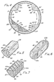
- FIGURE 1 is an isometric view of a mixer block.
- FIGURE 2 is a cut-away longitudinal view of the interior of a rotary kiln showing the use of mixer blocks in the refractory lining.
- FIGURE 3 is a view through 3-3 of FIGURE 2 showing the rotary kiln prior to the start of rotation with a mixer block extending upwardly into the bed of particles.
- FIGURE 4 shows the rotary kiln rotated about 45° clockwise from its original position in FIGURE 3 showing the position of the bed of particles during rotation of the kiln.
- FIGURES 5 and 6 are isometric views of two alternative embodiments of the mixer block.
- FIGURE 7 is an isometric view showing the use of a plurality of flights on the surfaces of the mixer block.
- It has been found that solid particles of a material can be mixed, dried, cooled, heated or calcined to produce a uniform product with minimal breakage of the particles and minimal formation of fines and dust in a generally horizontal rotary drum by incorporating a plurality of the mixer blocks in the interior of the drum. In the present disclosure and claims the terms rotary drum and rotary kiln are used interchangeably. The mixer block used in the rotary drum of the invention [as shown in FIGURE 1] ] is generally triangular in cross-section. The block can be made of any material, such as ferrous or non-ferrous metals or refractory material so long as the material will withstand the environment in which it is to be used. If made from ferrous or non-ferrous metals, the block can be made by bending a metallic plate into the desired shape or can be made by welding or brazing metallic plates together with a form which is generally triangular in cross-section. The block may also be preformed using refractory material or may be cast in situ using castable refractory materials. In the case of a rotary kiln used to heat solid particles, the mixer block as shown in FIGURE 1 is made from a refractory or coated with a refractory, for example magnesia, alumina, alumina-silica and the like, which desirably is the same refractory composition from which the refractory blocks comprising the refractory lining are made. The
mixer block 20 has a generallyrectangular base surface 21 and twoend surfaces 21 a and 21 b, and atop surface 24. Thebase surface 21 is generally rectangular and may be flat or slightly convex as shown in FIGURE 1. If it is convex it has a radius of curvature equal to the radius of curvature of the interior wall of the rotary drum or the hot face of the refractory lining in the kiln. The curvature is usually so slight that the surface may be considered to be flat. The mixer block is laid-up contiguous with the periphery of the interior of the drum or the hot face of the refractory lining. The side surfaces and end surfaces extend inwardly into the interior of the drum a distance at least equal to one-third the depth of the particles in the bottom of the drum. As the drum slowly rotates a convergingside surface 22 comes initially into contact with the particles. This firstconverging side surface 22 is hereinafter referred to as the leading surface. The second convergingsurface 23 is hereinafter referred to as the trailing surface. While we have said that the height of the mixer block is at least equal to one-third the depth of the particles in the drum, the mixer block may be large enough to extend beyond the surface of the particles. However, it is preferred to use a mixer block which is at least one-third the depth of the particles, but does not exceed about 90% of the depth of the particles. As noted previously, the leadingsurface 22 is the first surface of the mixer block to contact the particles as the drum rotates. The included angle "a" formed by the intersection of the leadingsurface 22 and thebase surface 21 should be about the same angle as the angle of repose of the material in the drum. However, the included angle can be within plus 10° to minus 10° of the angle of repose of the material in the drum. It is preferred, furthermore, to use an included angle which is within 5° or minus 5° of the angle of repose of the material. The angle of repose or rest angle of a material is the maximum angle with a horizontal plane at which loose material will stand on a horizontal base without sliding. It is often between 30° and 35°. In the case of limestone it is about 38°. - When the drum rotates, the material is lifted upwardly by the leading
surface 22 of themixer block 20 for a distance along the periphery of the interior surface in the drum. Because the slope of the converging surfaces is approximately equal to the angle of repose of the material, the particles roll or pass downwardly in layers over themselves to the bottom of the drum. Since the particles do not fall downwardly, undue breakage of the particles is eliminated and the production of fines and dust is minimized. The included angle "b" formed by the intersection of the trailingsurface 23 and thebase surface 21 is not as important as angle "a" and need not necessarily be equal to angle "a" but it is preferred that angle "b" also be within plus 10° to minus 10° and preferable plus 5° to minus 5° of the angle of repose of the material in the drum. - In the following description of the mixer block we will describe its use in a rotary kiln suitable for calcining flux material, such as limestone, dolomite, dolomitic limestone, magnesite, and the like although the invention is not limited to such use. As defined in Hackh's Chemical Dictionary, Julius Grant, 4th Edition, 1969, page 123, calcination is defined as "(1) oxide formation by heating oxy salts e.g. calcium oxide from calcite. (2) Expelling the volatile portions of a substance by heat." By calcination, therefore, we mean the formation of an oxide, for example calcium oxide or magnesium oxide, when heating limestone (calcium carbonate), magnesite (magnesium carbonate), dolomite (calcium and magnesium carbonate) and dolomitic limestone (calcium carbonate containing the double salt calcium and magnesium carbonate) to a temperature sufficiently high to expel carbon dioxide. In this case the mixer block is made of refractory similar to the refractory blocks in the refractory lining.
- Turning now to FIGURE 2, a rotary kiln is shown generally at 10. The
rotary kiln 10 includes an outer metallic shell 11 and arefractory lining 12 contiguous with theinterior surface 13 of the shell 11. Thekiln 10 has a feed orupstream end 14 and a discharge ordownstream end 15. Aburner 16 is provided at theend 15 of the kiln whereby hot gases are produced in thekiln 10. The hot gases flow countercurrently to the passage of the material 17 in thekiln 10. - The
refractory lining 12 extends the length of thekiln 10 and includes a plurality ofrefractory blocks 18. A plurality of mixer blocks 20 are laid up contiguous with the hot face of the refractory blocks at selected locations as shown along the length of thekiln 10. While only onemixer block 20 is shown at each location, a plurality of mixer blocks 20 (dependent upon the size of the kiln and hereinafter referred to as a set) are evenly spaced around the periphery of the refractory lining. Each set comprises at least four mixer blocks 20. However, dependent upon the size of the kiln, a set can be comprised of any number of blocks from at least, for example, four up to eight or ten mixer blocks spaced more or less evenly around the periphery of the inner wall of the kiln. The number of sets used in each kiln is dependent upon the length of the kiln. Each set of mixer blocks may be rotationally offset a desired distance from the adjacent set peripherally around the kiln. In the illustrated embodiment the sets of mixer blocks are rotationally offset 20°; however, the angle can be greater or lesser than 20°. Eachmixer block 20 is generally triangular in cross-section as shown in FIGURES 1 and 3. Of course it is possible to use sets of mixer blocks which form a continuous longitudinal line the length of the kiln rather than being offset as described above. - As noted previously and as shown in FIGURES 1 and 3, the
mixer block 20 has abase surface 21, twoend surfaces 21 a and 21 b and two converging side surfaces 22 and 23 which terminate in atop surface 24 as shown. The converging side surfaces 22 and 23 if extended would meet to form a sharp edge which is difficult to manufacture and which is subject to early breakage. Hence, themixer block 20 is preferably made with thetruncated surface 24. Thebase surface 21 can be a generally flat rectangular surface; it may also be convex to conform to the curvature of the refractory lining. The base surface is fitted to the refractory lining by placement in arecess 25a formed in the refractory blocks 18. The convergingside surface 22 is the first surface of the mixer block which contacts the particles of the material as the kiln rotates in a clockwise direction and is the leading surface. The second convergingside surface 23 is the trailing surface. The included angle "a" formed by the juncture or intersection of the leadingsurface 22 and thebase surface 21 may be plus 10° or minus 10° and preferably plus 5° or minus 5° of the angle of repose of the material being calcined. The included angle "b" formed by the juncture or intersection of the trailingsurface 23 and thebase surface 21 is also preferably plus 10° or minus 10° and preferably plus 5° or minus 5° of the angle of repose of the material being calcined. If thebase surface 21 is convex, the included angles "a" and "b" can be determined by passing a flat plane perpendicular to a radius of the kiln through the intersections of the converging side surfaces and the base surface. The angle formed by the intersection of the flat plane and the converging side surfaces forms the included angles "a" and "b". While the included angles "a" and "b" are not necessarily equal, it is preferred that the angles are equal or nearly so. - The
mixer block 20 can be a preformed shape or can be cast in situ. If a preformed shape is used, therefractory blocks 18 in therefractory lining 12 are installed either recessed as previously noted at the locations desired as shown at 25a or they can be made with the base surface having a radius of curvature equal to the radius of curvature of the refractory blocks 18. If cast in situ, thebottom surface 21 will be convex and have the same radius of curvature as the hot face of therefractory lining 12. In either case, themixer block 20 can be firmly held in place by conventional means such as bolts (shown in phantom in FIGURES 3 and 4) welded to the interior surface of the metallic shell 11 and extending radially inwardly a predetermined distance from the shell 11 to thereby provide an anchor to retain the mixer blocks in place. Of course, such means requires providing the necessary bores in the refractory blocks used in the refractory lining. The bores are filled with the same refractory as the refractory lining andmixer block 20. One such means of anchoring a refractory material is described in U.S. Patent 3,445,099 which describes a means for fastening castable refractory linings in a rotary kiln. Other suitable anchoring arrangements can also be used as will be apparent to those skilled in the art. - We have shown the mixer block as being solid; however, to conserve material and to reduce its weight, voids can be formed in the block by means well known in the art. For example, cardboard tubes of a desired size may be used and the refractory material formed around the tubes.
- FIGURE 4 shows the position of the material as
kiln 10 is rotating in a clockwise direction. - FIGURE 5 shows another embodiment of the
mixer block 20. In this embodiment themixer block 20 has a quadrilaterallower portion 25 and a generally triangularly shapedupper portion 26. Thelower portion 25 has aconvex bottom surface 27 which has the same radius of curvature as the interior 13 of the shell 11, and is laid contiguous with theinterior surface 13 of the shell 11. More specifically, thelower portion 25 has two generally rectangular side surfaces 28 and 29 which are contiguous with adjacentrefractory blocks 18 when fitted to therefractory lining 12. The generally triangularupper portion 26 is the same shape as described previously and has the same end and converging side surfaces; therefore we have used identical numbers for identification of these end and converging side surfaces. The included angles "a" and "b" can be determined by drawing a vertical line downwardly from thesurface 24 to the inner wall of the drum. A plane perpendicular to the vertical line is then drawn through the intersections of the side surfaces 28 and 22 and 29 and 23 respectively. The angles "a" and "b" formed by such perpendicular plane and the side surfaces 22 and 23, respectively, are taken as the included angles "a" and "b" of the triangular upper portion. Of course the perpendicular plane is the base surface of theupper portion 26 and the top surface of thelower portion 25. The included angles "a" and "b" can be as much as plus 10° or minus 10° but are preferably plus 5° and minus 5° of the angle of repose of the material in the kiln. In the case of limestone, the angle of repose is 38° therefore the included angles "a" and "b" can be between 48° and 28° and preferably between 43° and 33° (the showing applying equally to the other embodiments of the mixer blocks). - As shown in FIGURE 6, the end surfaces 21 a and 21 b can be substantially half-conical in shape. The half-conical shape on the downstream end of the block which may be either 21 a or 21 b provides easy flow of the hot combustion gases passing upstream in the kiln, around the block and also aids in the prevention of scale formation on such surface in kilns fired with coal. The half-conical shape on the upstream end surface of the block aids in the downstream flow of the solid particles around the block. The blocks may be made with one or both or either of the end surfaces half-conical in shape, however it is preferred that at least the downstream end surfaces have a half-conical shape.
- FIGURE 7 shows the use of a plurality of
flights 22a and 22b formed on the leading 22 and trailing 23 surfaces of themixer block 20. When material is charged into the feed end of the kiln, the material may build up at the feed end and spill out of the kiln. The flights aid in transporting the material away from the feed end thereby preventing the buildup and spillage of the material from the kiln. - To determine the breakage resulting from the use of mixer blocks in the rotary drum of the invention as compared to the breakage caused by lifter flights which are frequently used in such rotary kilns when calcining limestone, three test runs were made on a thirty inch (0.762 m) diameter kiln. In the first test run the kiln was equipped with one set of standard metallic lifters. The second test run was made with two sets of standard metallic lifters. The second test run was made with two sets of standard metallic lifters. The third test run was made using one set of the mixer blocks of the invention. Each test run was made by charging limestone having a particle size in the range of 1/4 inch by 6 mesh (U.S.S.) (6.35 mm x 3.36 mm) to the kiln at a feed rate of 20 pounds (9.07 kg.) per minute. The kiln was rotated at 1.25 rpm. All the test runs were made at room temperature. The product produced in each test run was screened. The results are shown below:

- It can be seen from the above test Nos. 1 and 2 that the use of conventional lifters in a kiln results in considerable breakage of the particles as they pass through the kiln whereas there is substantially no breakage of particles when using the mixer blocks of the invention as shown in test No. 3. The virtual absence of very fine particles in test Nos. 1 and 2 indicates that a portion of the particles have been reduced to a size which is so fine that they can be swept out of the kiln in the exhaust gases. Such fine particles are not produced when using the mixer blocks in the rotary drum of the invention as can be seen in test No. 3.
- In a specific example of the invention, aliquot quantities of limestone were calcined in a rotary kiln which was 35 feet (10.668 m) in length and had an inside diameter of 30 inches (0.762 m). Two batches of limestone were screened and found to have the following size consist:
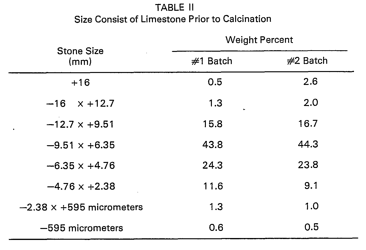
- The No. 1 Batch of limestone was fed at a rate of 20.6 pounds (9.344 kg) per minute into the 30 inch (0.762 m) diameter rotary kiln having a refractory lining which was devoid of any lifters or mixer blocks. The depth of the bed in the kiln was 3 inches (76.2 mm). The kiln was operated at a speed of 1.25 revolutions per minute. The temperature in the kiln was 1941°F (1061 °C). During the test run 12.5 pounds (5.67 kg) of lime per minute were produced. The calcined limestone or lime was screened and analyzed for CO2 content. The size consist and carbon dioxide (C02) content are shown below:

- The No. 2 Batch of limestone was fed into the same 30 inch (0.762 m) diameter kiln, however the kiln was provided with three sets of mixer blocks. The depth of the bed in the kiln was 4 inches (101.6 mm). The mixer blocks were 24 inches (0.609 m) in length and the height of the triangular portions was 2-7/8 inches (73.025 mm). Prior to rotating the kiln and with the bed of material and a mixer block at the bottom of the. kiln, it was found that the triangular portion of the mixer block extended 2-7/8 inches (73.025 mm) into the bed of material. This distance was equivalent to 72% of the depth of the bed. The mixer blocks were spaced 12 inches (0.304 m) apart along the length of the kiln and were 60° apart around the periphery of the interior of the kiln. Each set of mixer blocks was rotatably displaced 20° from the preceding set of mixer blocks. The limestone was fed at a rate of 20 pounds (9.072 kg) per minute. The kiln was operated at a speed of 1.25 revolutions per minute and at a temperature of 1945°F (1063°C). The production rate of the run was 10.2 pounds (4.627 kg) of lime per minute. The size consist and the carbon dioxide content of the lime are shown below:

- The calculated average carbon dioxide (C02) content of lime produced in a kiln not equipped with mixer blocks was 13.6 weight percent as seen in Table III, whereas the calculated average carbon dioxide (C02) content of lime produced in a kiln equipped with mixer blocks was 5.8 weight percent as seen in Table IV. The lime production rate in a kiln not equipped with mixer blocks was 12.6 pounds (5.715 kg) per minute whereas the lime production rate in a kiln equipped with mixer blocks was 10.2 pounds (4.627 kg) per minute. Although it may appear that the use of mixers results in a loss of lime production, this is not the case. The apparatent loss is actually due to a more thorough calcination of the limestone and the resulting larger amount of gaseous carbon dioxide which is removed during calcination when using the mixers of the invention. Thus a more thorough calcination of limestone is achieved in a kiln which is equipped with mixer blocks than in a kiln not equipped with mixer blocks.
- The middle fraction of the lime product produced when using the mixer blocks had a relatively low C02 content indicating the production of a more uniform lime product. The smaller amounts of the finer sizes when using the mixer blocks shows that the mixer blocks prevent undue breakage of the limestone during calcination.
- In another example of the invention, two batches of limestone were screened to determine the size consist before calcination and were calcined in the same kiln as described in the first specific example. The size consist of the calcined product was then determined. The kiln was operated at a speed of 1.25 revolutions per minute and a temperature of 1950°F (1066°C). The feed rate was kept constant at 20 pounds (9.072 kg) per minute. The first batch was calcined in the kiln without the use of lifters or mixer blocks and the second batch was calcined in the kiln equipped as described in the first specific example. The size consist of the feed material and calcined product are shown below:

- By the use of the mixer blocks in the refractory lining the interior of the kiln, a more uniformly calcined product is produced with little if any formation of dust and small particles due to breakage of the material being calcined, calcination occurred in less time than normally required to calcine the same amount of material to the same degree, thereby resulting in an energy saving.
- While we have shown the use of mixers in the calcination of flux stones such as limestone, dolomite, dolomitic limestone and the like, the mixers may also be used in rotary drums to dry such materials as sand and gravel, to heat materials to produce, for example, coke pellets suitable for calcination, fertilizers, and the coating of pellets.
- The rotary drum of the invention may be used for mixing, drying, cooling, heating, or calcining solid particles of a material preferably in particle form such as gravel, sand, stone, cementitious particle limestones, dolomite, dolomitic limestone, magnesite, fertilizers, catalysts, and the like.
Claims (13)
Applications Claiming Priority (2)
| Application Number | Priority Date | Filing Date | Title |
|---|---|---|---|
| US892367 | 1978-03-31 | ||
| US05/892,367 US4136965A (en) | 1978-03-31 | 1978-03-31 | Mixer block for use in rotary drums |
Publications (3)
| Publication Number | Publication Date |
|---|---|
| EP0004756A2 EP0004756A2 (en) | 1979-10-17 |
| EP0004756A3 EP0004756A3 (en) | 1979-10-31 |
| EP0004756B1 true EP0004756B1 (en) | 1983-06-22 |
Family
ID=25399848
Family Applications (1)
| Application Number | Title | Priority Date | Filing Date |
|---|---|---|---|
| EP79300527A Expired EP0004756B1 (en) | 1978-03-31 | 1979-03-30 | Rotary drum and method of mixing, drying, cooling, heating or calcining solid particles |
Country Status (6)
| Country | Link |
|---|---|
| US (1) | US4136965A (en) |
| EP (1) | EP0004756B1 (en) |
| JP (1) | JPS6051635B2 (en) |
| CA (1) | CA1110846A (en) |
| DE (1) | DE2965708D1 (en) |
| DK (1) | DK150287C (en) |
Cited By (1)
| Publication number | Priority date | Publication date | Assignee | Title |
|---|---|---|---|---|
| WO2017189018A3 (en) * | 2016-04-30 | 2018-02-22 | Hewlett-Packard Development Company, L.P. | Mixing powdered build material for additive manufacturing |
Families Citing this family (35)
| Publication number | Priority date | Publication date | Assignee | Title |
|---|---|---|---|---|
| US4522498A (en) * | 1978-01-23 | 1985-06-11 | Mendenhall Robert Lamar | Asphaltic concrete recycle apparatus and method |
| US4326809A (en) * | 1978-01-23 | 1982-04-27 | Mendenhall Robert Lamar | Recycling apparatus for asphaltic concrete |
| US4392822A (en) * | 1978-08-02 | 1983-07-12 | Klockner-Humboldt-Deutz Ag | System for burning fine-grained material, particularly for the manufacture of cement clinkers |
| US4398826A (en) * | 1980-04-14 | 1983-08-16 | Mendenhall Robert Lamar | Asphaltic concrete recycling apparatus |
| US4382682A (en) * | 1980-06-02 | 1983-05-10 | Mendenhall Robert Lamar | Recycling apparatus for particulate asphaltic concrete |
| US4480922A (en) * | 1980-08-22 | 1984-11-06 | Mendenhall Robert Lamar | Recycling apparatus for particulate asphaltic concrete |
| SE8106899L (en) * | 1981-11-19 | 1983-05-20 | Hoeganaes Ab | ELDFAST FOOD FOR OVEN |
| US4475886A (en) * | 1983-03-01 | 1984-10-09 | Kaiser Aluminum & Chemical Corporation | Lifter for rotary kiln |
| JPS59208382A (en) * | 1983-05-12 | 1984-11-26 | 松下電器産業株式会社 | Method of mixing and drying powder |
| JPS59184095U (en) * | 1983-05-26 | 1984-12-07 | 川崎炉材株式会社 | Combination bricks for rotary kiln scraping |
| JPS62273042A (en) * | 1986-05-21 | 1987-11-27 | Nec Corp | Ball mill |
| JPS634079A (en) * | 1986-06-23 | 1988-01-09 | Toppan Printing Co Ltd | Stirrer |
| JPS6322594U (en) * | 1986-07-30 | 1988-02-15 | ||
| US4970970A (en) * | 1989-06-26 | 1990-11-20 | Avery Solid Waste Incineration Co. | Drying and burning incinerator for trash |
| US5334012A (en) * | 1990-12-27 | 1994-08-02 | Astec Industries, Inc. | Combustion chamber having reduced NOx emissions |
| US5299933A (en) * | 1991-12-24 | 1994-04-05 | Quigley Company, Inc. | Rotary kiln with a polygonal lining |
| GB9405760D0 (en) * | 1994-03-23 | 1994-05-11 | Tioxide Group Services Ltd | Improved kiln |
| FR2725505B1 (en) * | 1994-10-11 | 1996-11-08 | Pa Technologies | ROTARY OVEN HAVING LIFTERS AND METHOD FOR REPAIRING SUCH OVENS |
| US6705323B1 (en) * | 1995-06-07 | 2004-03-16 | Conceptus, Inc. | Contraceptive transcervical fallopian tube occlusion devices and methods |
| US5645417A (en) * | 1995-10-09 | 1997-07-08 | Micron Technology, Inc. | Dimpled thermal processing furnace tube |
| US5702247A (en) * | 1996-06-06 | 1997-12-30 | Chemical Lime Company | Kiln lining and method |
| US5873714A (en) * | 1997-03-03 | 1999-02-23 | Reframerica, Inc. | Rotary kiln having a lining with a wave-shaped inner face |
| US5927969A (en) * | 1998-05-01 | 1999-07-27 | Harper International Corp. | Batch system cross-flow rotary calciner |
| ES2186610T3 (en) * | 2000-12-15 | 2003-05-16 | Cleanaway Deutschland Ag & Co | DEVICE FOR PURIFYING AND / OR DECONTAMINATING POLYESTERS. |
| US6883249B1 (en) | 2002-08-23 | 2005-04-26 | Internetek, Inc. | Dryer with insulating flights |
| JP2008122043A (en) * | 2006-11-15 | 2008-05-29 | Sumitomo Heavy Ind Ltd | Rotary kiln furnace |
| US9239189B2 (en) * | 2007-11-05 | 2016-01-19 | Ansac Pty Ltd | Kiln |
| US9080813B1 (en) * | 2010-04-12 | 2015-07-14 | George J. Deckebach | Adjusting rotational speeds of rotary kilns to increase solid/gas interaction |
| JP2013192492A (en) * | 2012-03-19 | 2013-09-30 | Omc Co Ltd | Liquid impregnation apparatus |
| CN102895982B (en) * | 2012-09-28 | 2017-10-13 | 彤程化学(中国)有限公司 | Catalyst roasting-shaping Liang rotation rotary kilns |
| JP6099083B2 (en) * | 2012-12-28 | 2017-03-22 | 太平洋マテリアル株式会社 | Method for producing quicklime-based expansion material and rotary kiln |
| WO2018000034A1 (en) * | 2016-06-28 | 2018-01-04 | Anthony Watkins | Method and apparatus for applying road surface markings |
| EP4053485A1 (en) * | 2021-03-05 | 2022-09-07 | S.A. Lhoist Recherche et Développement | Rotary kiln and method for firing carbonaceous material, in particular limestone or dolomite |
| EP4053484A1 (en) | 2021-03-05 | 2022-09-07 | S.A. Lhoist Recherche et Développement | Rotary kiln and method for firing carbonaceous material, in particular limestone or dolomite |
| EP4053483A1 (en) * | 2021-03-05 | 2022-09-07 | S.A. Lhoist Recherche et Développement | Rotary kiln and method for firing carbonaceous material, in particular limestone or dolomite |
Family Cites Families (11)
| Publication number | Priority date | Publication date | Assignee | Title |
|---|---|---|---|---|
| US1544504A (en) * | 1923-10-30 | 1925-06-30 | Clifford J Tomlinson | Rotary kiln |
| GB395729A (en) * | 1932-01-21 | 1933-07-21 | Mikael Vogel Jorgensen | Improvements in and relating to rotary kilns |
| US1920677A (en) * | 1932-09-16 | 1933-08-01 | Richard W Burke | Kiln lining |
| US2084713A (en) * | 1936-03-07 | 1937-06-22 | Quigley Co | Rotary kiln |
| US3423222A (en) * | 1965-05-10 | 1969-01-21 | Kenneth E Mcconnaughay | Method of making a paving composition |
| US3445099A (en) * | 1968-01-22 | 1969-05-20 | Kaiser Aluminium Chem Corp | Rotary kiln linings |
| US3563521A (en) * | 1969-02-26 | 1971-02-16 | California Portland Cement Co | Materials lifter construction and installation in kilns |
| DE2038790A1 (en) * | 1969-08-06 | 1971-02-11 | Prerowske Strojirny N P | Increasing the periphal breakaway angle for - materials in rotary shaft furnaces |
| US3592454A (en) * | 1969-08-07 | 1971-07-13 | California Portland Cement Co | Formless installation of materials lifters and kiln lining |
| US3627289A (en) * | 1970-06-22 | 1971-12-14 | Walter Erman | Apparatus and method for removing oil from metal turnings |
| JPS5017109U (en) * | 1973-06-13 | 1975-02-24 |
-
1978
- 1978-03-31 US US05/892,367 patent/US4136965A/en not_active Expired - Lifetime
-
1979
- 1979-02-12 CA CA321,310A patent/CA1110846A/en not_active Expired
- 1979-03-09 DK DK097779A patent/DK150287C/en active
- 1979-03-27 JP JP54035144A patent/JPS6051635B2/en not_active Expired
- 1979-03-30 EP EP79300527A patent/EP0004756B1/en not_active Expired
- 1979-03-30 DE DE7979300527T patent/DE2965708D1/en not_active Expired
Cited By (1)
| Publication number | Priority date | Publication date | Assignee | Title |
|---|---|---|---|---|
| WO2017189018A3 (en) * | 2016-04-30 | 2018-02-22 | Hewlett-Packard Development Company, L.P. | Mixing powdered build material for additive manufacturing |
Also Published As
| Publication number | Publication date |
|---|---|
| JPS6051635B2 (en) | 1985-11-14 |
| EP0004756A2 (en) | 1979-10-17 |
| JPS54133405A (en) | 1979-10-17 |
| DE2965708D1 (en) | 1983-07-28 |
| CA1110846A (en) | 1981-10-20 |
| US4136965A (en) | 1979-01-30 |
| DK97779A (en) | 1979-10-01 |
| EP0004756A3 (en) | 1979-10-31 |
| DK150287B (en) | 1987-01-26 |
| DK150287C (en) | 1987-11-30 |
Similar Documents
| Publication | Publication Date | Title |
|---|---|---|
| US4136965A (en) | Mixer block for use in rotary drums | |
| AU679430B2 (en) | Rotary kiln with a polygonal lining | |
| US3965240A (en) | High density magnesia pellet and method for making same | |
| US5702247A (en) | Kiln lining and method | |
| EP1060354B1 (en) | Fabricated steel lifter for rotary kiln | |
| US2861356A (en) | Apparatus for cooling granular materials | |
| US2282584A (en) | Method of operating rotary kilns | |
| EP0674145B1 (en) | Rotary kiln wall equipped with a plurality of protrusions | |
| JP3122229B2 (en) | Vertical firing furnace | |
| KR100249734B1 (en) | Method of producing powdered calcium oxide | |
| CN209957658U (en) | A uniformly heated lime calciner | |
| CN108793791A (en) | A kind of the drying and calcining method and its equipment of bulk material | |
| KR100729131B1 (en) | Continuous method for manufacturing conidia lime and its manufacturing apparatus | |
| US2036952A (en) | Apparatus for the treatment of cement raw materials | |
| CN223154014U (en) | Quantitative feeding device for limestone calcination | |
| JPH0313468Y2 (en) | ||
| SU1190167A1 (en) | Rotating furnace with heat exchange lining for alumina calcination | |
| CN101209928A (en) | Corundum processing technology | |
| RU54419U1 (en) | ROTARY FURNACE LINING | |
| KR100573585B1 (en) | Rotary kiln for manufacturing high quality quicklime | |
| JPS60200081A (en) | Firebrick and rotary kiln, on inside thereof firebrick is lined | |
| US3689044A (en) | Method of operating a cement kiln | |
| SU904415A1 (en) | Chain curtain of rotary furnace | |
| RU2211404C2 (en) | Process of burning of worn tires | |
| SU844963A1 (en) | Rotary furnace |
Legal Events
| Date | Code | Title | Description |
|---|---|---|---|
| PUAI | Public reference made under article 153(3) epc to a published international application that has entered the european phase |
Free format text: ORIGINAL CODE: 0009012 |
|
| PUAL | Search report despatched |
Free format text: ORIGINAL CODE: 0009013 |
|
| AK | Designated contracting states |
Designated state(s): BE DE FR GB IT LU NL SE |
|
| AK | Designated contracting states |
Designated state(s): BE DE FR GB IT LU NL SE |
|
| 17P | Request for examination filed | ||
| ITF | It: translation for a ep patent filed | ||
| GRAA | (expected) grant |
Free format text: ORIGINAL CODE: 0009210 |
|
| AK | Designated contracting states |
Designated state(s): BE DE FR GB IT LU NL SE |
|
| REF | Corresponds to: |
Ref document number: 2965708 Country of ref document: DE Date of ref document: 19830728 |
|
| ET | Fr: translation filed | ||
| KL | Correction list |
Free format text: 84/01 NEUDRUCK |
|
| ET1 | Fr: translation filed ** revision of the translation of the patent or the claims | ||
| PGFP | Annual fee paid to national office [announced via postgrant information from national office to epo] |
Ref country code: FR Payment date: 19840312 Year of fee payment: 6 |
|
| PGFP | Annual fee paid to national office [announced via postgrant information from national office to epo] |
Ref country code: DE Payment date: 19840313 Year of fee payment: 6 |
|
| PGFP | Annual fee paid to national office [announced via postgrant information from national office to epo] |
Ref country code: LU Payment date: 19840323 Year of fee payment: 6 |
|
| PG25 | Lapsed in a contracting state [announced via postgrant information from national office to epo] |
Ref country code: LU Free format text: LAPSE BECAUSE OF NON-PAYMENT OF DUE FEES Effective date: 19840331 |
|
| PGFP | Annual fee paid to national office [announced via postgrant information from national office to epo] |
Ref country code: SE Payment date: 19840331 Year of fee payment: 6 Ref country code: BE Payment date: 19840331 Year of fee payment: 6 |
|
| NLR4 | Nl: receipt of corrected translation in the netherlands language at the initiative of the proprietor of the patent | ||
| PLBE | No opposition filed within time limit |
Free format text: ORIGINAL CODE: 0009261 |
|
| STAA | Information on the status of an ep patent application or granted ep patent |
Free format text: STATUS: NO OPPOSITION FILED WITHIN TIME LIMIT |
|
| 26N | No opposition filed | ||
| PGFP | Annual fee paid to national office [announced via postgrant information from national office to epo] |
Ref country code: NL Payment date: 19870331 Year of fee payment: 9 |
|
| PG25 | Lapsed in a contracting state [announced via postgrant information from national office to epo] |
Ref country code: SE Effective date: 19880331 |
|
| BERE | Be: lapsed |
Owner name: BETHLEHEM STEEL CORP. Effective date: 19880331 |
|
| PG25 | Lapsed in a contracting state [announced via postgrant information from national office to epo] |
Ref country code: NL Effective date: 19881001 |
|
| NLV4 | Nl: lapsed or anulled due to non-payment of the annual fee | ||
| PG25 | Lapsed in a contracting state [announced via postgrant information from national office to epo] |
Ref country code: GB Free format text: LAPSE BECAUSE OF NON-PAYMENT OF DUE FEES Effective date: 19881117 |
|
| GBPC | Gb: european patent ceased through non-payment of renewal fee | ||
| PG25 | Lapsed in a contracting state [announced via postgrant information from national office to epo] |
Ref country code: FR Free format text: LAPSE BECAUSE OF NON-PAYMENT OF DUE FEES Effective date: 19881130 |
|
| PG25 | Lapsed in a contracting state [announced via postgrant information from national office to epo] |
Ref country code: DE Effective date: 19881201 |
|
| REG | Reference to a national code |
Ref country code: FR Ref legal event code: ST |
|
| PG25 | Lapsed in a contracting state [announced via postgrant information from national office to epo] |
Ref country code: BE Effective date: 19890331 |
|
| EUG | Se: european patent has lapsed |
Ref document number: 79300527.3 Effective date: 19881130 |