EP0004465A2 - Method of regenerating adsorbents - Google Patents
Method of regenerating adsorbents Download PDFInfo
- Publication number
- EP0004465A2 EP0004465A2 EP79300466A EP79300466A EP0004465A2 EP 0004465 A2 EP0004465 A2 EP 0004465A2 EP 79300466 A EP79300466 A EP 79300466A EP 79300466 A EP79300466 A EP 79300466A EP 0004465 A2 EP0004465 A2 EP 0004465A2
- Authority
- EP
- European Patent Office
- Prior art keywords
- adsorbent
- zones
- gas stream
- zone
- carbon dioxide
- Prior art date
- Legal status (The legal status is an assumption and is not a legal conclusion. Google has not performed a legal analysis and makes no representation as to the accuracy of the status listed.)
- Withdrawn
Links
Images

Classifications
-
- B—PERFORMING OPERATIONS; TRANSPORTING
- B01—PHYSICAL OR CHEMICAL PROCESSES OR APPARATUS IN GENERAL
- B01D—SEPARATION
- B01D53/00—Separation of gases or vapours; Recovering vapours of volatile solvents from gases; Chemical or biological purification of waste gases, e.g. engine exhaust gases, smoke, fumes, flue gases, aerosols
- B01D53/02—Separation of gases or vapours; Recovering vapours of volatile solvents from gases; Chemical or biological purification of waste gases, e.g. engine exhaust gases, smoke, fumes, flue gases, aerosols by adsorption, e.g. preparative gas chromatography
- B01D53/04—Separation of gases or vapours; Recovering vapours of volatile solvents from gases; Chemical or biological purification of waste gases, e.g. engine exhaust gases, smoke, fumes, flue gases, aerosols by adsorption, e.g. preparative gas chromatography with stationary adsorbents
- B01D53/0462—Temperature swing adsorption
-
- C—CHEMISTRY; METALLURGY
- C01—INORGANIC CHEMISTRY
- C01B—NON-METALLIC ELEMENTS; COMPOUNDS THEREOF; METALLOIDS OR COMPOUNDS THEREOF NOT COVERED BY SUBCLASS C01C
- C01B3/00—Hydrogen; Gaseous mixtures containing hydrogen; Separation of hydrogen from mixtures containing it; Purification of hydrogen
- C01B3/50—Separation of hydrogen or hydrogen containing gases from gaseous mixtures, e.g. purification
- C01B3/56—Separation of hydrogen or hydrogen containing gases from gaseous mixtures, e.g. purification by contacting with solids; Regeneration of used solids
-
- C—CHEMISTRY; METALLURGY
- C07—ORGANIC CHEMISTRY
- C07C—ACYCLIC OR CARBOCYCLIC COMPOUNDS
- C07C7/00—Purification; Separation; Use of additives
- C07C7/12—Purification; Separation; Use of additives by adsorption, i.e. purification or separation of hydrocarbons with the aid of solids, e.g. with ion-exchangers
-
- F—MECHANICAL ENGINEERING; LIGHTING; HEATING; WEAPONS; BLASTING
- F25—REFRIGERATION OR COOLING; COMBINED HEATING AND REFRIGERATION SYSTEMS; HEAT PUMP SYSTEMS; MANUFACTURE OR STORAGE OF ICE; LIQUEFACTION SOLIDIFICATION OF GASES
- F25J—LIQUEFACTION, SOLIDIFICATION OR SEPARATION OF GASES OR GASEOUS OR LIQUEFIED GASEOUS MIXTURES BY PRESSURE AND COLD TREATMENT OR BY BRINGING THEM INTO THE SUPERCRITICAL STATE
- F25J3/00—Processes or apparatus for separating the constituents of gaseous or liquefied gaseous mixtures involving the use of liquefaction or solidification
- F25J3/02—Processes or apparatus for separating the constituents of gaseous or liquefied gaseous mixtures involving the use of liquefaction or solidification by rectification, i.e. by continuous interchange of heat and material between a vapour stream and a liquid stream
- F25J3/04—Processes or apparatus for separating the constituents of gaseous or liquefied gaseous mixtures involving the use of liquefaction or solidification by rectification, i.e. by continuous interchange of heat and material between a vapour stream and a liquid stream for air
- F25J3/04151—Purification and (pre-)cooling of the feed air; recuperative heat-exchange with product streams
- F25J3/04157—Afterstage cooling and so-called "pre-cooling" of the feed air upstream the air purification unit and main heat exchange line
-
- B—PERFORMING OPERATIONS; TRANSPORTING
- B01—PHYSICAL OR CHEMICAL PROCESSES OR APPARATUS IN GENERAL
- B01D—SEPARATION
- B01D2253/00—Adsorbents used in seperation treatment of gases and vapours
- B01D2253/10—Inorganic adsorbents
- B01D2253/106—Silica or silicates
- B01D2253/108—Zeolites
-
- B—PERFORMING OPERATIONS; TRANSPORTING
- B01—PHYSICAL OR CHEMICAL PROCESSES OR APPARATUS IN GENERAL
- B01D—SEPARATION
- B01D2256/00—Main component in the product gas stream after treatment
- B01D2256/16—Hydrogen
-
- B—PERFORMING OPERATIONS; TRANSPORTING
- B01—PHYSICAL OR CHEMICAL PROCESSES OR APPARATUS IN GENERAL
- B01D—SEPARATION
- B01D2256/00—Main component in the product gas stream after treatment
- B01D2256/24—Hydrocarbons
- B01D2256/245—Methane
-
- B—PERFORMING OPERATIONS; TRANSPORTING
- B01—PHYSICAL OR CHEMICAL PROCESSES OR APPARATUS IN GENERAL
- B01D—SEPARATION
- B01D2257/00—Components to be removed
- B01D2257/50—Carbon oxides
- B01D2257/504—Carbon dioxide
-
- B—PERFORMING OPERATIONS; TRANSPORTING
- B01—PHYSICAL OR CHEMICAL PROCESSES OR APPARATUS IN GENERAL
- B01D—SEPARATION
- B01D2257/00—Components to be removed
- B01D2257/80—Water
-
- B—PERFORMING OPERATIONS; TRANSPORTING
- B01—PHYSICAL OR CHEMICAL PROCESSES OR APPARATUS IN GENERAL
- B01D—SEPARATION
- B01D2259/00—Type of treatment
- B01D2259/40—Further details for adsorption processes and devices
- B01D2259/40011—Methods relating to the process cycle in pressure or temperature swing adsorption
- B01D2259/40043—Purging
- B01D2259/4005—Nature of purge gas
- B01D2259/40056—Gases other than recycled product or process gas
-
- B—PERFORMING OPERATIONS; TRANSPORTING
- B01—PHYSICAL OR CHEMICAL PROCESSES OR APPARATUS IN GENERAL
- B01D—SEPARATION
- B01D2259/00—Type of treatment
- B01D2259/40—Further details for adsorption processes and devices
- B01D2259/40011—Methods relating to the process cycle in pressure or temperature swing adsorption
- B01D2259/40077—Direction of flow
- B01D2259/40081—Counter-current
-
- B—PERFORMING OPERATIONS; TRANSPORTING
- B01—PHYSICAL OR CHEMICAL PROCESSES OR APPARATUS IN GENERAL
- B01D—SEPARATION
- B01D2259/00—Type of treatment
- B01D2259/40—Further details for adsorption processes and devices
- B01D2259/40083—Regeneration of adsorbents in processes other than pressure or temperature swing adsorption
- B01D2259/40088—Regeneration of adsorbents in processes other than pressure or temperature swing adsorption by heating
- B01D2259/4009—Regeneration of adsorbents in processes other than pressure or temperature swing adsorption by heating using hot gas
-
- B—PERFORMING OPERATIONS; TRANSPORTING
- B01—PHYSICAL OR CHEMICAL PROCESSES OR APPARATUS IN GENERAL
- B01D—SEPARATION
- B01D2259/00—Type of treatment
- B01D2259/40—Further details for adsorption processes and devices
- B01D2259/402—Further details for adsorption processes and devices using two beds
-
- B—PERFORMING OPERATIONS; TRANSPORTING
- B01—PHYSICAL OR CHEMICAL PROCESSES OR APPARATUS IN GENERAL
- B01D—SEPARATION
- B01D2259/00—Type of treatment
- B01D2259/40—Further details for adsorption processes and devices
- B01D2259/414—Further details for adsorption processes and devices using different types of adsorbents
- B01D2259/4141—Further details for adsorption processes and devices using different types of adsorbents within a single bed
- B01D2259/4145—Further details for adsorption processes and devices using different types of adsorbents within a single bed arranged in series
-
- B—PERFORMING OPERATIONS; TRANSPORTING
- B01—PHYSICAL OR CHEMICAL PROCESSES OR APPARATUS IN GENERAL
- B01D—SEPARATION
- B01D2259/00—Type of treatment
- B01D2259/40—Further details for adsorption processes and devices
- B01D2259/416—Further details for adsorption processes and devices involving cryogenic temperature treatment
-
- C—CHEMISTRY; METALLURGY
- C01—INORGANIC CHEMISTRY
- C01B—NON-METALLIC ELEMENTS; COMPOUNDS THEREOF; METALLOIDS OR COMPOUNDS THEREOF NOT COVERED BY SUBCLASS C01C
- C01B2203/00—Integrated processes for the production of hydrogen or synthesis gas
- C01B2203/04—Integrated processes for the production of hydrogen or synthesis gas containing a purification step for the hydrogen or the synthesis gas
- C01B2203/042—Purification by adsorption on solids
- C01B2203/043—Regenerative adsorption process in two or more beds, one for adsorption, the other for regeneration
-
- C—CHEMISTRY; METALLURGY
- C01—INORGANIC CHEMISTRY
- C01B—NON-METALLIC ELEMENTS; COMPOUNDS THEREOF; METALLOIDS OR COMPOUNDS THEREOF NOT COVERED BY SUBCLASS C01C
- C01B2203/00—Integrated processes for the production of hydrogen or synthesis gas
- C01B2203/04—Integrated processes for the production of hydrogen or synthesis gas containing a purification step for the hydrogen or the synthesis gas
- C01B2203/0465—Composition of the impurity
- C01B2203/0475—Composition of the impurity the impurity being carbon dioxide
-
- C—CHEMISTRY; METALLURGY
- C01—INORGANIC CHEMISTRY
- C01B—NON-METALLIC ELEMENTS; COMPOUNDS THEREOF; METALLOIDS OR COMPOUNDS THEREOF NOT COVERED BY SUBCLASS C01C
- C01B2203/00—Integrated processes for the production of hydrogen or synthesis gas
- C01B2203/04—Integrated processes for the production of hydrogen or synthesis gas containing a purification step for the hydrogen or the synthesis gas
- C01B2203/0465—Composition of the impurity
- C01B2203/0495—Composition of the impurity the impurity being water
-
- Y—GENERAL TAGGING OF NEW TECHNOLOGICAL DEVELOPMENTS; GENERAL TAGGING OF CROSS-SECTIONAL TECHNOLOGIES SPANNING OVER SEVERAL SECTIONS OF THE IPC; TECHNICAL SUBJECTS COVERED BY FORMER USPC CROSS-REFERENCE ART COLLECTIONS [XRACs] AND DIGESTS
- Y02—TECHNOLOGIES OR APPLICATIONS FOR MITIGATION OR ADAPTATION AGAINST CLIMATE CHANGE
- Y02C—CAPTURE, STORAGE, SEQUESTRATION OR DISPOSAL OF GREENHOUSE GASES [GHG]
- Y02C20/00—Capture or disposal of greenhouse gases
- Y02C20/40—Capture or disposal of greenhouse gases of CO2
-
- Y—GENERAL TAGGING OF NEW TECHNOLOGICAL DEVELOPMENTS; GENERAL TAGGING OF CROSS-SECTIONAL TECHNOLOGIES SPANNING OVER SEVERAL SECTIONS OF THE IPC; TECHNICAL SUBJECTS COVERED BY FORMER USPC CROSS-REFERENCE ART COLLECTIONS [XRACs] AND DIGESTS
- Y02—TECHNOLOGIES OR APPLICATIONS FOR MITIGATION OR ADAPTATION AGAINST CLIMATE CHANGE
- Y02P—CLIMATE CHANGE MITIGATION TECHNOLOGIES IN THE PRODUCTION OR PROCESSING OF GOODS
- Y02P20/00—Technologies relating to chemical industry
- Y02P20/151—Reduction of greenhouse gas [GHG] emissions, e.g. CO2
Definitions
- This invention relates to the regeneration of adsorbents.
- the gas feed stream is passed through the adsorbents which remove carbon dioxide and water from the gas. Water is preferentially adsorbed and adsorption is generally continued until carbon dioxide is about to break through the adsorbent. The adsorbent is then regenerated.
- the aim of the present invention is to provide a new method of regenerating adsorbent which is commercially competitive with the patented techniques of others and, at least in its preferred embodiments, is more thermally efficient than such techniques.
- a method for the regeneration of adsorbents used in the adsorption of water and carbon dioxide contaminants from a feed gas stream passed sequentially through first and second adsorbent zones containing adsorbent wherein the water is adsorbed in the first adsorbent zone and carbon dioxide is adsorbed in the second adsorbent zone which comprises:
- the adsorbent is a molecular sieve, for example 13X molecular sieve, although other adsorbents, for example activated carbon, could also be used.
- the regeneration is carried out at a pressure between atmospheric (14.7 psig) and 100 psig. Since adsorption would typically be carried out between 90 and 3000 psig the present invention preferably also includes the step of depressurizing the first and second adsorbent zones preferably through the first adsorbent zone prior to step (a) above.
- the heated regeneration gas will be at a temperature between 300°F and 450°F although temperatures outside this range could also be used, for example, between 250°F and 500°F.
- the cool regeneration gas is between 40°F and 130°F although lower temperatures could also be used.
- the present invention also provides a method for separating water and carbon dioxide from a feed gas stream which comprises, in sequence:
- first and second adsorbent zones can be physically separate and distinct or can be formed a single bed of adsorbent separated into said zones by, for example, an inlet for introducing heated regeneration gas.
- the feed gas stream can conveniently consist of air although feed gas streams in which the major component is hydrogen or methane can also be used.
- valves 18A and 30A are closed and valves 18B and 30B are opened thereby ensuring a reasonably uniform supply of purified air through line 32.
- Figure 2 shows diagramatically the distribution of water and carbon dioxide in the adsorber at the end of an adsorbtion cycle. (To simplify the diagrams beds 24A and 26A have been drawn as one continuous bed).
- the pressure in adsorber 22A is first let down to atmospheric. This is achieved by first opening valve 318A which permits the air in the vessel to vent via lines 20A, 310A, 320, orifice 322 and vent 122.
- the orifice 322 is 0.75 inches in diameter which is sufficiently small to inhibit the molecular sieve leaving the adsorber 22A with the air.
- valve 318A When the pressure in the adsorber 22A reaches 600 psia valve 318A is closed and valve 314A is opened thereby permitting the adsorber 22A to vent through lines 20A, 310A, 312A, orifice 316 and vent 122.
- the orifice 316 is 1.00 inches in diameter.
- valves 318A and 314A are closed and valves l16A and 110 opened.
- Waste nitrogen which is substantially free of impurities, and which is obtained from the air separation plant through line 100, passes through valve 102 and is compressed to 19 psia in compressor 104.
- the hot nitrogen then passes through lines 114 and l14A via valve 116A.
- the balance of the nitrogen leaving the compressor 104 passes through line 208 and enters heat exchanger 212 via valve 210.
- the nitrogen is further cooled in heat exchanger 214 to 40°F and passes through valve 220 and lines 222 and 226 to orifice 228.
- the orifice 228 restricts the flow of nitrogen which passes through line 226 and valve 230A before entering the bottom of adsorber 22A at 40 0 F.
- the purpose of introducing nitrogen into the bottom of adsorber 22A is to inhibit hot nitrogen from line 114A passing downwardly through the adsorber 22A and conveying desorbed carbon dioxide to the bottom of the adsorber 22A.
- hot nitrogen has desorbed a substantial portion of the carbon dioxide from the lower portion of the bed 24A but little or no water.
- the portion of the bed 24A containing carbon dioxide is at less than 100°F whilst the water is wholly contained within a zone which, at this stage, is at about 40°F. It will be noted that a small amount of carbon dioxide has been desorbed from bed 26A.
- valve 224A is opened and valve 230A and 116A are closed.
- About 4000 lbs/hr of nitrogen leaves refrigerator 214 at 40°F and is passed upwardly through adsorber 22A desorbing the carbon dioxide contained in bed 26A and simultaneously cooling bed 24A. Initially little or no carbon dioxide is adsorbed in bed 24A but as its temperature falls a certain amount of carbon dioxide is adsorbed so that after twenty minutes the distribution of the carbon dioxide in the adsorber is somewhat as shown in Figure 6.whereas after a further 32 minutes it is as shown in Figure 7.
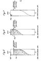
- the total regeneration time is 138 minutes.
- adsorber 22A is on stream adsorbing carbon dioxide and water.
- adsorber 22B has completed its adsorbtion cycle, adsorber 22A is placed on stream and the beds 24B and 26B are regenerated. Regeneration is carried out in the manner set out hereinbefore except that the suffix "B" should be used wherever the suffix "A” appears and vice-versa.
- the upper beds 24A and 24B were each 84 inches in diameter and 12 inches deep and contained 1,200 lbs of 13X molecular sieve.
- the lower beds 26A and 26B were each 84 inches in diameter and 48 inches deep and contained 5300 lbs each of 1/8 inch 13X molecular sieve.
- valve 318 was opened to allow the vessel to depressurize at a rate determined by orifice 322. After the pressure has fallen by a pre-determined amount the valve 120A was opened to vent the remaining air direct to atmosphere. Depressurization was effected over 15 minutes.
Landscapes
- Chemical & Material Sciences (AREA)
- Engineering & Computer Science (AREA)
- Organic Chemistry (AREA)
- Oil, Petroleum & Natural Gas (AREA)
- Analytical Chemistry (AREA)
- Water Supply & Treatment (AREA)
- General Engineering & Computer Science (AREA)
- Thermal Sciences (AREA)
- Physics & Mathematics (AREA)
- Mechanical Engineering (AREA)
- Combustion & Propulsion (AREA)
- Inorganic Chemistry (AREA)
- General Chemical & Material Sciences (AREA)
- Chemical Kinetics & Catalysis (AREA)
- Separation Of Gases By Adsorption (AREA)
- Solid-Sorbent Or Filter-Aiding Compositions (AREA)
Abstract
Water and carbon dioxide contaminants are removed from a feed gas stream by adsorption in first and second adsorbent zones arranged in series. Regeneration of the adsorbent zones is accomplished by (a) introducing a heated regeneration gas intermediate the first and second adsorbent zones and passing the heated regeneration gas through the first adsorbent zone; and (b) subsequently passing a low temperature regeneration gas sequentially through the second and first adsorbent zones.
Description
- This invention relates to the regeneration of adsorbents.
- During the past few years it has become increasingly common to use adsorbents for removing carbon dioxide and water from gas feed streams..One application is-the removal of carbon dioxide and water from air prior to its cryogenic fractionation into oxygen, nitrogen and argon. Other applications include the removal of carbon dioxide and water from natural gas and from hydrogen rich streams.
- In all the known applications, the gas feed stream is passed through the adsorbents which remove carbon dioxide and water from the gas. Water is preferentially adsorbed and adsorption is generally continued until carbon dioxide is about to break through the adsorbent. The adsorbent is then regenerated.
- Various methods of regeneration have been proposed as, for example described in U.S. Patents 3,150,192; 3,710,547 and 3,738,084 and French Patent 2,005,910.
- The aim of the present invention is to provide a new method of regenerating adsorbent which is commercially competitive with the patented techniques of others and, at least in its preferred embodiments, is more thermally efficient than such techniques.
- According to the present invention there is provided a method for the regeneration of adsorbents used in the adsorption of water and carbon dioxide contaminants from a feed gas stream passed sequentially through first and second adsorbent zones containing adsorbent wherein the water is adsorbed in the first adsorbent zone and carbon dioxide is adsorbed in the second adsorbent zone, which comprises:
- (a) introducing a heated regeneration gas stream intermediate the first and second adsorbent zones, and passing the heated regeneration gas through the first adsorbent zone in a direction countercurrent to the flow of the feed gas stream therethrough; and subsequently
- (b) passing cool regeneration gas sequentially through the second and first adsorbent zones in a direction countercurrent to the flow of the feed gas stream therethrough..
- Preferably, the adsorbent is a molecular sieve, for example 13X molecular sieve, although other adsorbents, for example activated carbon, could also be used.
- Preferably, the regeneration is carried out at a pressure between atmospheric (14.7 psig) and 100 psig. Since adsorption would typically be carried out between 90 and 3000 psig the present invention preferably also includes the step of depressurizing the first and second adsorbent zones preferably through the first adsorbent zone prior to step (a) above.
- Advantageously, the heated regeneration gas will be at a temperature between 300°F and 450°F although temperatures outside this range could also be used, for example, between 250°F and 500°F.
- Preferably the cool regeneration gas is between 40°F and 130°F although lower temperatures could also be used.
- The present invention also provides a method for separating water and carbon dioxide from a feed gas stream which comprises, in sequence:
- (a) passing the feed gas stream at a pressure of from 90 to 3000 psig and a temperature of from 40°F to 120°F sequentially through first and second adsorbent zones containing adsorbent, wherein substantially all of the water is adsorbed in the first adsorbent zone and carbon dioxide is adsorbed in the second adsorbent zone;
- (b) discontinuing the flow of the feed gas stream to the first and second adsorbent zones;
- (c) depressurizing the first and second adsorbent zones through the first adsorbtion zone to a regeneration pressure of between 14.7 and 100 psig;
- (d) introducing heated regeneration gas at a temperature between 3000F and 450°F intermediate the first and second adsorbent zones, and passing the heated regeneration gas through the first adsorbent zone in a direction countercurrent to the flow of the feed gas stream therethrough; and
- (e) passing cool regeneration gas at a temperature between 40°F and 130°F sequentially through the second and first adsorbent zones in a direction countercurrent to the flow of the feed gas stream therethrough.
- It will be appreciated that during the step of introducing the heated regeneration gas intermediate the first and second adsorbent zones part of the heated regeneration gas could be allowed to flow through the second adsorbent zone. .This is not, however, preferred since the heated regeneration gas would tend to push the adsorbed carbon dioxide away from the first adsorbent zone. Therefore, preferably, in both the above methods, during the step of introducing the heated regeneration gas intermediate the first and second adsorbent zones, sufficient cool regeneration gas is passed through the second adsorbent zone in the direction of the first adsorbent zone to inhibit passage of the heated regeneration gas through the second adsorbent zone.
- It should be appreciated that the first and second adsorbent zones can be physically separate and distinct or can be formed a single bed of adsorbent separated into said zones by, for example, an inlet for introducing heated regeneration gas.
- The feed gas stream can conveniently consist of air although feed gas streams in which the major component is hydrogen or methane can also be used.
- For a better understanding of the invention and to show how the same may be carried into effect reference will now be made, by way of example-, to the accompanying drawings in which:
- Figure 1 is a schematic representation of a preferred embodiment of apparatus for practicing the invention; and
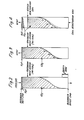
- Figures 2 to 7 are diagrams showing the composition of an adsorber at the end of an adsorption cycle and at different times during regeneration.
- Referring to Figure 1, 7587 lb. moles/hour of moisture laden air at 1950 psia and 40°F are passed through
line 10 intoseparator 12. A certain amount of water leaves theseparator 12 throughline 16 whilst the saturated air passes intoadsorber 22A vialines 14, 14A and 20A andopen valve 18A. Theadsorber 22A contains twobeds adsorber 22A throughlines open valve 30A. The purified air is passed to a cryogenic air separation plant of conventional design (not shown). - As the air passes through the
beds bed 26A. At this point, four hours after adsorbtion commences,valves valves 18B and 30B are opened thereby ensuring a reasonably uniform supply of purified air throughline 32. - Figure 2 shows diagramatically the distribution of water and carbon dioxide in the adsorber at the end of an adsorbtion cycle. (To simplify the
diagrams beds - In order to regenerate the
beds adsorber 22A is first let down to atmospheric. This is achieved byfirst opening valve 318A which permits the air in the vessel to vent vialines vent 122. The orifice 322 is 0.75 inches in diameter which is sufficiently small to inhibit the molecular sieve leaving theadsorber 22A with the air. - When the pressure in the
adsorber 22A reaches 600psia valve 318A is closed andvalve 314A is opened thereby permitting theadsorber 22A to vent throughlines orifice 316 andvent 122. Theorifice 316 is 1.00 inches in diameter. When the pressure has dropped to 50psia valve 318A is reopened. As the pressure in theadsorber 22A approachesatmospheric valve 120A is opened thereby permitting the remaining air to vent throughlines - During pressure let down a small amount of carbon dioxide is desorbed as is a very small quantity of water. The distribution of water and carbon dioxide in the
adsorber 22A after pressure let down is shown in Figure 3. - At the end of the pressure let down
valves - Waste nitrogen, which is substantially free of impurities, and which is obtained from the air separation plant through
line 100, passes throughvalve 102 and is compressed to 19 psia incompressor 104. - The majority of the compressed nitrogen, which leaves the
compressor 104 at 130°F then passes throughvalve 110 andline 108 intoelectric heater 112 where it is heated to 450o F. The hot nitrogen then passes throughlines 114 and l14A via valve 116A. The balance of the nitrogen leaving thecompressor 104 passes throughline 208 and enters heat exchanger 212 viavalve 210. The nitrogen is further cooled in heat exchanger 214 to 40°F and passes through valve 220 andlines 222 and 226 to orifice 228. Theorifice 228 restricts the flow of nitrogen which passes through line 226 and valve 230A before entering the bottom ofadsorber 22A at 400F. The purpose of introducing nitrogen into the bottom ofadsorber 22A is to inhibit hot nitrogen fromline 114A passing downwardly through theadsorber 22A and conveying desorbed carbon dioxide to the bottom of theadsorber 22A. - The flow of hot nitrogen through
line 114A and throughline 226A is continued for 33 minutes after which the lower portion of thebed 24A between theline 114A and the top of theadsorber 22A is at about 450°F whilst the temperature in the remainder of thebed 24A decreases to about 40°F at the top. As shown in Figure 4, hot nitrogen has desorbed a substantial portion of the carbon dioxide from the lower portion of thebed 24A but little or no water. In this connection the portion of thebed 24A containing carbon dioxide is at less than 100°F whilst the water is wholly contained within a zone which, at this stage, is at about 40°F. It will be noted that a small amount of carbon dioxide has been desorbed frombed 26A. - After the thirty three minutes have elapsed
electric heater 112 is turned off but the flow of nitrogen (at 130°F) is allowed to continue for a further 23 minutes. During this time the heat in thebed 24A is transferred towards the top of theadsorber 22A which rises in temperature to between 150°F and 200°F. All of the carbon dioxide inbed 24A and substantially all the water is desorbed during this time leaving the distribution of the carbon dioxide and water in the adsorber somewhat as shown in Figure 5. - At the end of the 23
minutes valve 224A is opened and valve 230A and 116A are closed. About 4000 lbs/hr of nitrogen leaves refrigerator 214 at 40°F and is passed upwardly throughadsorber 22A desorbing the carbon dioxide contained inbed 26A and simultaneously coolingbed 24A. Initially little or no carbon dioxide is adsorbed inbed 24A but as its temperature falls a certain amount of carbon dioxide is adsorbed so that after twenty minutes the distribution of the carbon dioxide in the adsorber is somewhat as shown in Figure 6.whereas after a further 32 minutes it is as shown in Figure 7. The carbon dioxide remaining at the end of this period is sufficiently small to be ignored and theadsorber 22A is repressurized by closingvalves opening valve 412 thereby allowing high pressure air to pass throughline 410. Orifice 414 is sized so that theadsorber 22A is repressurized in 15 minutes. - The total regeneration time is 138 minutes.
- It will be appreciated that whilst the
beds adsorber 22A are being regenerated adsorber 22B is on stream adsorbing carbon dioxide and water. When adsorber 22B has completed its adsorbtion cycle,adsorber 22A is placed on stream and thebeds 24B and 26B are regenerated. Regeneration is carried out in the manner set out hereinbefore except that the suffix "B" should be used wherever the suffix "A" appears and vice-versa. - The apparatus shown in Figure 1 was then converted for use at low pressure. In
particular lines 312, 312A and 312B, together with their associatedvalves orifice 316 were omitted due-to the lower pressure. - The
upper beds lower beds 26A and 26B were each 84 inches in diameter and 48 inches deep and contained 5300 lbs each of 1/8 inch 13X molecular sieve. - In use, 2700 lb. moles per hour of saturated air at 134 psia and containing 400 ppm (by volume) carbon dioxide were passed through
adsorber 22A for two hours. The flow of air was then diverted to adsorber 22B whilst the molecular sieve inadsorber 22A was regenerated by the following cycle. - Firstly, valve 318 was opened to allow the vessel to depressurize at a rate determined by orifice 322. After the pressure has fallen by a pre-determined amount the
valve 120A was opened to vent the remaining air direct to atmosphere. Depressurization was effected over 15 minutes. - Secondly, 9000 lbs per hour of nitrogen heated to approximately 450°F by
heater 112 were passed into theadsorber 22A vialine 114A. Simultaneously, a small flow of cool nitrogen at 40°F was introduced into the bottom of theadsorber 22A vialine 226A. After 35 minutes theheater 112 was turned off but the flow of nitrogen was maintained for a further 11 minutes. - After this further period the flow of nitrogen through
line 114A was re-directed vialines adsorber 22A for a further 19 minutes.Valve 218 was then closed and the entire flow of nitrogen passed through refrigerator 214 to arrive atadsorber 22A at 40°F. This flow of nitrogen was passed through theadsorber 22A for a further 40 minutes after which theadsorber 22A was repressurized for over a 15 minute period. In this particular case the times of adsorbtion and regeneration were equal.
Claims (8)
1. A method for the regeneration of adsorbents used in the adsorption of water and carbon dioxide contaminants from a feed gas stream passed sequentially through first and second adsorbent zones containing adsorbent wherein the water is adsorbed in the first adsorbent zone and carbon dioxide is adsorbed in the second adsorbent zone, characterized in that it comprises:
(a) introducing a heated regeneration gas stream intermediate the first and second adsorbent zones, and passing the heated regeneration gas through the first adsorbent zone in a direction countercurrent to the flow of the feed gas stream therethrough; and subsequently
(b) passing cool regeneration gas sequentially through the second and first adsorbent zones in a direction countercurrent to the flow of the feed gas stream therethrough.
2. A method according to Claim 1, wherein the adsorption has been carried on at a high pressure level, characterized in that it further comprising the step of depressurizing the first and second adsorbent zones through the first adsorbent zone prior to step (a).
3. A method according to Claim 1 or 2, characterized in that said heated regeneration gas is at a temperature between 3000F and 450°F.
4. A method according to Claim 1, 2 or 3, characterized in that said cool regeneration gas is between 40°F and 130°F.
5. A method for separating water and carbon dioxide from a feed gas stream characterized in that it comprises, in sequence:
(a) passing the feed gas stream at a pressure of from 90 to 3000 psig and a temperature of from 40°F to 120°F sequentially through first and second adsorbent zones containing adsorbent, wherein substantially all of the water is adsorbed in the first adsorbent zone and carbon dioxide is adsorbed in the second adsorbent zone;
(b) discontinuing the flow of the feed gas stream to the first and second adsorbent zones;
(c) depressurizing the first and second adsorbent zones through the first adsorbtion zone to a regeneration pressure of between 14.7 and 100 psig;
(d) introducing heated regeneration gas at a temperature between 3000F and 450°F intermediate the first and second adsorbent zones, and passing the heated regeneration gas through the first adsorbent zone in a direction countercurrent to the flow of the feed gas stream therethrough; and
(e) passing cool regeneration gas at a temperature between 40°F and 130°F sequentially through the second and first adsorbent zones in a direction countercurrent to the flow of the feed gas stream therethrough.
6. A method according to any preceding Claim, characterized in that during the step of introducing a heated regeneration gas intermediate the first and second adsorbent zones, sufficient cool regeneration gas is passed through the second adsorbent zone in the direction of the first adsorbent zone to inhibit passage of the heated regeneration gas through the second adsorbent zone.
7. A method according to to any preceding Claim, wherein said feed gas stream is air.
8. A method according to any of Claims 1 to 6, wherein the major component of said feed gas stream is hydrogen or methane.
Applications Claiming Priority (2)
| Application Number | Priority Date | Filing Date | Title |
|---|---|---|---|
| US88977978A | 1978-03-24 | 1978-03-24 | |
| US889779 | 1978-03-24 |
Publications (2)
| Publication Number | Publication Date |
|---|---|
| EP0004465A2 true EP0004465A2 (en) | 1979-10-03 |
| EP0004465A3 EP0004465A3 (en) | 1979-10-31 |
Family
ID=25395776
Family Applications (1)
| Application Number | Title | Priority Date | Filing Date |
|---|---|---|---|
| EP79300466A Withdrawn EP0004465A3 (en) | 1978-03-24 | 1979-03-23 | Method of regenerating adsorbents |
Country Status (3)
| Country | Link |
|---|---|
| EP (1) | EP0004465A3 (en) |
| BR (1) | BR7901782A (en) |
| ZA (1) | ZA791382B (en) |
Cited By (14)
| Publication number | Priority date | Publication date | Assignee | Title |
|---|---|---|---|---|
| EP0016558A1 (en) * | 1979-02-28 | 1980-10-01 | Air Products And Chemicals, Inc. | Vacuum swing adsorption for air fractionation |
| DE3122701A1 (en) * | 1981-06-06 | 1982-12-23 | Bergwerksverband Gmbh, 4300 Essen | METHOD FOR SEPARATING GAS MIXTURES BY MEANS OF PRESSURE CHANGE TECHNOLOGY |
| EP0146082A2 (en) * | 1983-12-15 | 1985-06-26 | Linde Aktiengesellschaft | Process for the separation of water vapour and carbon dioxide from a gas stream by adsorption |
| US4812147A (en) * | 1985-11-08 | 1989-03-14 | Union Carbide Corporation | Multicomponent adsorption process |
| EP0463535A1 (en) * | 1990-06-18 | 1992-01-02 | Praxair Technology, Inc. | Hybrid prepurifier for cryogenic air separation plants |
| EP0612554A1 (en) * | 1993-02-25 | 1994-08-31 | The BOC Group plc | Purification method and apparatus |
| EP0733393A1 (en) * | 1995-03-21 | 1996-09-25 | The Boc Group, Inc. | Removal of carbon dioxide from gas streams |
| US5593475A (en) * | 1995-04-13 | 1997-01-14 | Liquid Air Engineering Corporation | Mixed bed adsorber |
| EP0766989A1 (en) * | 1995-10-04 | 1997-04-09 | Air Products And Chemicals, Inc. | Purification of gases using solid adsorbents |
| US5766311A (en) * | 1996-07-03 | 1998-06-16 | Praxair Technology, Inc. | Multi-thermal pulse PSA system |
| WO2007106958A1 (en) * | 2006-03-17 | 2007-09-27 | Atlas Copco Airpower, Naamloze Vennootschap | Device for drying compressed gas and method applied thereby |
| JP2019177314A (en) * | 2018-03-30 | 2019-10-17 | 大陽日酸株式会社 | Gas refining apparatus and gas refining method |
| EP3671087A1 (en) * | 2018-12-21 | 2020-06-24 | L'air Liquide, Societe Anonyme Pour L'etude Et L'exploitation Des Procedes Georges Claude | A method and apparatus for eliminating heat bumps following regeneration of adsorbers in an air separation unit |
| US11029086B2 (en) | 2018-12-21 | 2021-06-08 | L'air Liquide Societe Anonyme Pour L'etude Et L'exploitation Des Procedes Georges Claude | Method and apparatus for reducing process disturbances during pressurization of an adsorber in an air separation unit |
Citations (4)
| Publication number | Priority date | Publication date | Assignee | Title |
|---|---|---|---|---|
| US3216178A (en) * | 1955-11-10 | 1965-11-09 | Air Liquide | Process for regenerating an adsorbent bed |
| FR1517092A (en) * | 1967-02-03 | 1968-03-15 | Air Liquide | Process for the purification of a gas by adsorption |
| DE1769135B1 (en) * | 1968-04-10 | 1970-12-03 | Messer Griesheim Gmbh | METHOD FOR MANUFACTURING SINTER BODIES FROM AL A METHOD FOR MANUFACTURING SINTER BODIES FROM AL |
| FR2174879A1 (en) * | 1972-03-03 | 1973-10-19 | British Gas Corp |
-
1979
- 1979-03-22 ZA ZA791382A patent/ZA791382B/en unknown
- 1979-03-22 BR BR7901782A patent/BR7901782A/en unknown
- 1979-03-23 EP EP79300466A patent/EP0004465A3/en not_active Withdrawn
Patent Citations (4)
| Publication number | Priority date | Publication date | Assignee | Title |
|---|---|---|---|---|
| US3216178A (en) * | 1955-11-10 | 1965-11-09 | Air Liquide | Process for regenerating an adsorbent bed |
| FR1517092A (en) * | 1967-02-03 | 1968-03-15 | Air Liquide | Process for the purification of a gas by adsorption |
| DE1769135B1 (en) * | 1968-04-10 | 1970-12-03 | Messer Griesheim Gmbh | METHOD FOR MANUFACTURING SINTER BODIES FROM AL A METHOD FOR MANUFACTURING SINTER BODIES FROM AL |
| FR2174879A1 (en) * | 1972-03-03 | 1973-10-19 | British Gas Corp |
Cited By (24)
| Publication number | Priority date | Publication date | Assignee | Title |
|---|---|---|---|---|
| EP0016558A1 (en) * | 1979-02-28 | 1980-10-01 | Air Products And Chemicals, Inc. | Vacuum swing adsorption for air fractionation |
| DE3122701A1 (en) * | 1981-06-06 | 1982-12-23 | Bergwerksverband Gmbh, 4300 Essen | METHOD FOR SEPARATING GAS MIXTURES BY MEANS OF PRESSURE CHANGE TECHNOLOGY |
| EP0146082A2 (en) * | 1983-12-15 | 1985-06-26 | Linde Aktiengesellschaft | Process for the separation of water vapour and carbon dioxide from a gas stream by adsorption |
| US4627856A (en) * | 1983-12-15 | 1986-12-09 | Linde Aktiengesellschaft | Process for the adsorptive separation of steam and a less readily adsorbable component from a gaseous stream |
| EP0146082A3 (en) * | 1983-12-15 | 1987-01-07 | Linde Aktiengesellschaft | Process for the separation of water vapour and carbon dioxide from a gas stream by adsorption |
| US4812147A (en) * | 1985-11-08 | 1989-03-14 | Union Carbide Corporation | Multicomponent adsorption process |
| EP0463535A1 (en) * | 1990-06-18 | 1992-01-02 | Praxair Technology, Inc. | Hybrid prepurifier for cryogenic air separation plants |
| EP0612554A1 (en) * | 1993-02-25 | 1994-08-31 | The BOC Group plc | Purification method and apparatus |
| US5447558A (en) * | 1993-02-25 | 1995-09-05 | The Boc Group Plc | Purification method and apparatus |
| EP0733393A1 (en) * | 1995-03-21 | 1996-09-25 | The Boc Group, Inc. | Removal of carbon dioxide from gas streams |
| US5593475A (en) * | 1995-04-13 | 1997-01-14 | Liquid Air Engineering Corporation | Mixed bed adsorber |
| EP0766989A1 (en) * | 1995-10-04 | 1997-04-09 | Air Products And Chemicals, Inc. | Purification of gases using solid adsorbents |
| US5766311A (en) * | 1996-07-03 | 1998-06-16 | Praxair Technology, Inc. | Multi-thermal pulse PSA system |
| WO2007106958A1 (en) * | 2006-03-17 | 2007-09-27 | Atlas Copco Airpower, Naamloze Vennootschap | Device for drying compressed gas and method applied thereby |
| BE1017002A3 (en) * | 2006-03-17 | 2007-11-06 | Atlas Copco Airpower Nv | DEVICE FOR DRYING COMPRESSED GAS AND METHOD THEREOF APPLIED |
| AU2007229279B2 (en) * | 2006-03-17 | 2010-08-19 | Atlas Copco Airpower, Naamloze Vennootschap | Device for drying compressed gas and method applied thereby |
| US7789938B2 (en) | 2006-03-17 | 2010-09-07 | Atlas Copco Airpower, Naamloze Vennootschap | Device for drying compressed gas and method applied thereby |
| CN101405070B (en) * | 2006-03-17 | 2012-07-04 | 艾拉斯科普库空气动力股份有限公司 | Device for drying compressed gas and method applied thereby |
| NO341140B1 (en) * | 2006-03-17 | 2017-08-28 | Atlas Copco Airpower Nv | Apparatus for drying compressed gas and method used for this |
| JP2019177314A (en) * | 2018-03-30 | 2019-10-17 | 大陽日酸株式会社 | Gas refining apparatus and gas refining method |
| EP3671087A1 (en) * | 2018-12-21 | 2020-06-24 | L'air Liquide, Societe Anonyme Pour L'etude Et L'exploitation Des Procedes Georges Claude | A method and apparatus for eliminating heat bumps following regeneration of adsorbers in an air separation unit |
| CN111346473A (en) * | 2018-12-21 | 2020-06-30 | 乔治洛德方法研究和开发液化空气有限公司 | Method and apparatus for eliminating thermal disturbances attendant to regeneration of an adsorber in an air separation unit |
| US11029086B2 (en) | 2018-12-21 | 2021-06-08 | L'air Liquide Societe Anonyme Pour L'etude Et L'exploitation Des Procedes Georges Claude | Method and apparatus for reducing process disturbances during pressurization of an adsorber in an air separation unit |
| US11137205B2 (en) | 2018-12-21 | 2021-10-05 | L'air Liquide Societe Anonyme Pour L'etude Et L'exploitation Des Procedes Georges Claude | Method and apparatus for eliminating heat bumps following regeneration of adsorbers in an air separation unit |
Also Published As
| Publication number | Publication date |
|---|---|
| BR7901782A (en) | 1979-11-20 |
| EP0004465A3 (en) | 1979-10-31 |
| ZA791382B (en) | 1980-04-30 |
Similar Documents
| Publication | Publication Date | Title |
|---|---|---|
| EP0016558B1 (en) | Vacuum swing adsorption for air fractionation | |
| US4000990A (en) | Adsorption process | |
| EP0042159B1 (en) | Air fractionation by pressure swing adsorption | |
| US3594983A (en) | Gas-treating process and system | |
| US5232474A (en) | Pre-purification of air for separation | |
| AU626494B2 (en) | Pre-purification of air for separation | |
| US5125934A (en) | Argon recovery from argon-oxygen-decarburization process waste gases | |
| US3957463A (en) | Oxygen enrichment process | |
| US4359328A (en) | Inverted pressure swing adsorption process | |
| US8268045B2 (en) | Compressed air producing method and producing plant | |
| EP0004465A2 (en) | Method of regenerating adsorbents | |
| KR100227060B1 (en) | Process and apparatus for gas purification | |
| US5220797A (en) | Argon recovery from argon-oxygen-decarburization process waste gases | |
| US3221476A (en) | Adsorption-desorption method | |
| JPH0587286B2 (en) | ||
| US3928004A (en) | Purification of inert gases | |
| US3149934A (en) | Cyclic adsorption process | |
| JPS6247050B2 (en) | ||
| WO1990006162A1 (en) | Process for separating condensable gas from non-condensable gas | |
| EP0756143B1 (en) | Adsorption process with high and low pressure feed streams | |
| US3086339A (en) | Technique with the fractionation or separation of components in a gaseous feed stream | |
| KR100605549B1 (en) | Apparatus for producting oxygen and control method the same | |
| US3696587A (en) | Adsorption process for recovering easy-to-regenerate condensible components from a multicomponent gas stream | |
| JPS6246911A (en) | Method for concentrating gaseous co | |
| Sircar | Air fractionation by adsorption |
Legal Events
| Date | Code | Title | Description |
|---|---|---|---|
| PUAI | Public reference made under article 153(3) epc to a published international application that has entered the european phase |
Free format text: ORIGINAL CODE: 0009012 |
|
| PUAL | Search report despatched |
Free format text: ORIGINAL CODE: 0009013 |
|
| AK | Designated contracting states |
Designated state(s): BE DE FR GB NL |
|
| AK | Designated contracting states |
Designated state(s): BE DE FR GB NL |
|
| STAA | Information on the status of an ep patent application or granted ep patent |
Free format text: STATUS: THE APPLICATION IS DEEMED TO BE WITHDRAWN |
|
| 18D | Application deemed to be withdrawn | ||
| RIN1 | Information on inventor provided before grant (corrected) |
Inventor name: HVIZDOS, LEONARD JAMES |