EP0004275B1 - Apparatus for remotely repairing tubes in a steam generator - Google Patents
Apparatus for remotely repairing tubes in a steam generator Download PDFInfo
- Publication number
- EP0004275B1 EP0004275B1 EP79100295A EP79100295A EP0004275B1 EP 0004275 B1 EP0004275 B1 EP 0004275B1 EP 79100295 A EP79100295 A EP 79100295A EP 79100295 A EP79100295 A EP 79100295A EP 0004275 B1 EP0004275 B1 EP 0004275B1
- Authority
- EP
- European Patent Office
- Prior art keywords
- boom
- column
- tubesheet
- carriage
- disposed
- Prior art date
- Legal status (The legal status is an assumption and is not a legal conclusion. Google has not performed a legal analysis and makes no representation as to the accuracy of the status listed.)
- Expired
Links
Images



Classifications
-
- G—PHYSICS
- G21—NUCLEAR PHYSICS; NUCLEAR ENGINEERING
- G21C—NUCLEAR REACTORS
- G21C17/00—Monitoring; Testing ; Maintaining
- G21C17/003—Remote inspection of vessels, e.g. pressure vessels
- G21C17/01—Inspection of the inner surfaces of vessels
-
- F—MECHANICAL ENGINEERING; LIGHTING; HEATING; WEAPONS; BLASTING
- F22—STEAM GENERATION
- F22B—METHODS OF STEAM GENERATION; STEAM BOILERS
- F22B37/00—Component parts or details of steam boilers
- F22B37/002—Component parts or details of steam boilers specially adapted for nuclear steam generators, e.g. maintenance, repairing or inspecting equipment not otherwise provided for
- F22B37/003—Maintenance, repairing or inspecting equipment positioned in or via the headers
-
- Y—GENERAL TAGGING OF NEW TECHNOLOGICAL DEVELOPMENTS; GENERAL TAGGING OF CROSS-SECTIONAL TECHNOLOGIES SPANNING OVER SEVERAL SECTIONS OF THE IPC; TECHNICAL SUBJECTS COVERED BY FORMER USPC CROSS-REFERENCE ART COLLECTIONS [XRACs] AND DIGESTS
- Y02—TECHNOLOGIES OR APPLICATIONS FOR MITIGATION OR ADAPTATION AGAINST CLIMATE CHANGE
- Y02E—REDUCTION OF GREENHOUSE GAS [GHG] EMISSIONS, RELATED TO ENERGY GENERATION, TRANSMISSION OR DISTRIBUTION
- Y02E30/00—Energy generation of nuclear origin
- Y02E30/30—Nuclear fission reactors
-
- Y—GENERAL TAGGING OF NEW TECHNOLOGICAL DEVELOPMENTS; GENERAL TAGGING OF CROSS-SECTIONAL TECHNOLOGIES SPANNING OVER SEVERAL SECTIONS OF THE IPC; TECHNICAL SUBJECTS COVERED BY FORMER USPC CROSS-REFERENCE ART COLLECTIONS [XRACs] AND DIGESTS
- Y10—TECHNICAL SUBJECTS COVERED BY FORMER USPC
- Y10T—TECHNICAL SUBJECTS COVERED BY FORMER US CLASSIFICATION
- Y10T29/00—Metal working
- Y10T29/49—Method of mechanical manufacture
- Y10T29/49718—Repairing
Definitions
- a cantilevered tool holder 57 is fastened to the platform 47 and coupled to the drive motor 49.
- the cantilevered tool holder has a tool receptacle or chuck 59 on the distal end thereof for holding a tool and a train of gears 62 or other drive means connects the drive motor 49 to the tool chuck 59 providing power to drive the tool 61.
Landscapes
- Physics & Mathematics (AREA)
- Engineering & Computer Science (AREA)
- High Energy & Nuclear Physics (AREA)
- General Engineering & Computer Science (AREA)
- Thermal Sciences (AREA)
- Mechanical Engineering (AREA)
- Plasma & Fusion (AREA)
- Monitoring And Testing Of Nuclear Reactors (AREA)
- Investigating Or Analyzing Materials By The Use Of Magnetic Means (AREA)
Description
- The present invention relates to nuclear steam generators and more particularly to apparatus for remotely repairing the tubes and tubesheet in a nuclear steam generator.
- In pressurized water nuclear reactors primary fluid or coolant is pumped through a reactor and a steam generator, radioactive contaminants in the primary fluid are deposited on the tubes and in the channel head of the steam generator so that repair crews are subjected to significant radioactivity when working within the channel head. Therefore, in order to reduce the exposure of personnel to radiation, it is desirable to provide an apparatus which can be remotely operated and effectively inspect and repair the tubes and tubesheets within the steam generator. The apparatus, however, must be installed and it is necessary for the repair crews to reach into, and work in close proximity of, the radioactive channel head.
- Apparatus of the kind referred to is described in U.S. Patent Specification 3 934 731.
- The principal object of the present invention is to provide an apparatus for remotely repairing tubes in a steam generator with which the repair crew's exposure to radiation is reduced to a minimum.
- With this object in view, the present invention resides in an apparatus for remotely repairing a tubesheet and tubes accessible from a head of a steam generator, which has a centrally disposed partition dividing the head into an inlet and an outlet portion and a manway disposed in each of said portions, said apparatus comprising a column rotatably disposed in a portion of said head generally perpendicular to said tubesheet, a boom pivotally mounted on said column, means for rotating said column and said boom therewith, means for locking said column and said boom in any rotated position, means for pivoting said boom from a position generally parallel to said tubesheet to a position generally aligned with said manway, a carriage disposed to ride lengthwise along said boom, means for moving said carriage lengthwise along said boom and for fixing the position of said carriage on said boom, and a tool holder mounted on said carriage, characterized in that said column is rotatably mounted on said partition at least near the upper end of the column and the top end of said column terminates a predetermined distance below said tubesheet, said boom extending over the top end of said column such that operations on one-half of the tubesheet and all of the tubes disposed in said half of the tubesheet can be performed by said apparatus.
- Preferably, there are hydraulic cylinders for pivoting the boom from its operating position generally parallel to the tubesheet to a position generally aligned with the axis of a manway to facilitate mounting of tools on the beam.
- With this arrangement. all the tubes and the whole tubesheet can be serviced as the support column is not connected to the tubesheet and the tool holder can move any place below the tubesheet.
- The invention will become more readily apparent from the following description of a preferred embodiment thereof shown, by way of example only, in the accompanying drawings, in which:
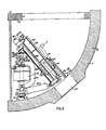
- Figure 1 is a partial sectional view of a head of a steam generator with apparatus for remotely repairing the tubes and tubesheets made in accordance with this invention disposed therein;
- Figure 2 is a partial sectional view of a head of a steam generator with the apparatus in a different position;
- Figure 3 is a partial sectional view of a carriage and tool holder utilized in this invention;
- Figure 4 is a partial sectional view of the carriage and tool holder;
- Figure 5 is an exploded view partially in section showing the attachment of a boom to a column; and
- Figure 6 is a sectional view taken on line VI-VI of Figure 1.
- Figures 1 and 2 show a portion of a channel head 1 of a steam generator 2 having a tubesheet 3 with a plurality of holes 5 disposed therein. Tubes 7 are disposed in the holes 5 and extend upwardly from the tubesheet 3. The channel head 1 has generally hemispherical walls 9 and is divided into an inlet portion and an outlet portion (only one of which is shown in the drawings) by a dividing plate 11. Each portion has a
manway 12 disposed in the wall 9. - Apparatus for remotely repairing and inspecting the tubes 7 and tubesheet 3 is disposed in one portion of the channel head 1 and comprises a vertically oriented
column 13 which is pivotally connected to the wall 9 of the channel head 1 and extends generally upwardly therefrom. Thecolumn 13 is generally perpendicular to the tubesheet 3 and disposed adjacent the. dividing plate 11. A spherical bearing block, which contains tapered roller bearing 15 is disposed'at the foot of thecolumn 13 in aspherical housing 17, which is fastened to the wall 9 by welding or other means and forms a first support means for thecolumn 13. A second support means 18 is fastened to the dividing plate 11 by welding or other means and is disposed adjacent the intermediate portion of thecolumn 13. Thecolumn 13 is rotatably disposed within the second support means 18 by an antifriction bearing such as ball or roller bearings (not shown). The second support means 18 also has asplit collar 19 disposed thereon. Thesplit collar 19 has agap 20, which is closed by ahydraulic cylinder 21 to lock thecolumn 13 in any of its rotated positions. - As shown in Figures 1 and 6 the
second support 18 has X and Y adjustments in a plane generally parallel to the tubesheet for aligning the column generally perpendicular to the tubesheet 3. One degree of movement, X, is afforded by a dovetail 22 and adjustingscrew 23. Aset screw 24 locks the dovetail 22 in position when the column is plum in one direction. The other degree of movement, Y, is provided by jackscrews 25 and clevis mountedbolts 26, or other means, such as shims. - The terminal or upper end of the
column 13 terminates a predetermined distance from the tubesheet 3. - A
boom 27 is pivotally connected to the terminal or upper end of thecolumn 13 by asuitable mounting bracket 28. The pivotal connection is such that theboom 27 rotates with thecolumn 13 and can pivot from a position generally parallel to the tubesheet 3 to a position generally aligned with themanway 12. A pair of telescoping hydraulic cylinders 29 (only one is shown) are pivotally connected to the lower end of thecolumn 13 by a suitable bracket 30 and to the distal end of theboom 27 by anotherbracket 31 to provide means for pivoting theboom 27 from a position generally parallel to the tubesheet 3 to a position generally aligned with themanway 12. - A hollow
shaft DC motor 32 is disposed over thecolumn 13 and is connected thereto. Themotor 32 has abase 33 with adjustable feet 35, which engage the dividing plate 11 to provide means for rotating thecolumn 13 and theboom 27 therewith. Disposed within the motor are rotary induction means for indicating the angular position of the hollow shaft and a tachometer for speed control. Themotor 32 is reversible so that it can rotate thecolumn 13 andboom 27 in either direction. - The
boom 27 comprises a pair of generally parallel rails orchannels 37 withways 39 on the top and bottom portion of eachchannel 37. Theways 39 extend longitudinally along the boom and are parallel to each other. Acarriage 41 is slidably disposed on theways 39. Thecarriage 41 has fourbearings 43, which slidably engage theways 39 so that the carriage moves rectilinearly and parallel to the longitudinal axis of theboom 27. - The
carriage 41, as shown best in Figures 3 and 4, comprises abaseplate 45 and aplatform 47 disposed generally parallel to each other and generally parallel to the tubesheet 3, when the longitudinal axis of theboom 27 is parallel thereto. Thebaseplate 45 is connected to thebearings 43 and theplatform 47 is disposed above and parallel to thebaseplate 45. Anair motor 49 or other drive means is connected to theplatform 47. - Means for guiding the
platform 47 with respect to thebaseplate 45 and for maintaining parallelism therebetween comprises fourround bars 51, which are affixed adjacent the four corners of theplatform 47, eitherball bushings 53 disposed in thebaseplate 45 for slidably receiving thebars 51, and a pair of double actinghydraulic cylinders 55 connected to the baseplate 45 a,.':: theplatform 47. Means for indicating the speed and position of theplatform 47 with respect to thebaseplate 45 is shown generally at 56. - A cantilevered
tool holder 57 is fastened to theplatform 47 and coupled to thedrive motor 49. The cantilevered tool holder has a tool receptacle orchuck 59 on the distal end thereof for holding a tool and a train ofgears 62 or other drive means connects thedrive motor 49 to thetool chuck 59 providing power to drive the tool 61. - Referring back to Figures 1 and 2, a
ball screw 63, drivenmotor 65 andball nut 67 are cooperatively associated with theboom 27 andcarriage 41 to provide means for moving the carriage rectilinearly along theboom 27 and for holding thecarriage 41 at any position along theboom 27. Theball screw 63 extends the length of theboom 27 and is disposed generally parallel to the longitudinal axis thereof. Theball nut 67 is affixed to thecarriage 41 and engages the threads on thescrew 63. Resolvers 68 are provided for indicating the position of the carriage along the boom. - Disposed on the
boom 27 are a pair of hydraulic cylinders 69 which havepiston rods 71 that can be extended outwardly to contact the wall 9 of the head 1 to steady theboom 27 when the tool 61 is performing an operation on the tubes 7 or tubesheet 3. - The cantilevered
tool holder 57, as shown best in Figure 4, hasarcuate plates 73 equally spaced on opposite sides of the axis of thedrive motor 49. Lugs 75 clamp thearcuate plates 73 andtool holder 57 to theplatform 47. Locating pins and bushings (not shown) are provided in the arcuate plate and in the platform so that the cantilevered tool holder can be aligned with the axis of the boom as shown in Figure 1, rotated 180° as shown in Figure 2 or rotated to form an acute angle with respect to the axis of the boom as shown in Figure 4 or any other position desired. The varying positions of the tool holder andshort column 13 cooperate to provide access to all of the tubes in one-half of the tubesheet and establish accurate positioning of the tool holder to allow remotely-controlled- repeated operation on any tube in that half of the tubesheet. - A C-shaped stiffening bracket 77 is fastened to the
column 13 spanning themotor 32 in order to reduce the deflection in thecolumn 13. - As shown in Figure 5 the upper or terminal end of the
column 13 has ataper 79 machined thereon. Themounting bracket 28 has acollar 81 disposed thereon. Thecollar 81 has ataper 83 counter-cored therein so that thetapers column 13 to theboom 27 without relative movement therebetween. Acapscrew 85 or some other type of fastener is provided to bring thetapers boom 27 to rotate with thecolumn 13 and be removable from thecolumn 13. - Hydraulic cylinders 69 are disposed on the
boom 27 and have apiston rod 71, which when extended contacts the wall 9 to help support and steady the distal end of theboom 27. - The apparatus hereinbefore described may be easily and quickly installed inside the channel head of a steam generator and with an assortment of tools can perform various operations on all of the tubes in one-half of the tubesheet. The apparatus so structured is rugged and reliable so that it can operate within the close tolerances necessary to retube a steam generator utilizing remote controls. To operate remotely, the angular position of the boom and column must be repeatable. Accurate angular positioning and indicating the angular position of the column and the boom is provided by the motor and
positioning package 32 and once the column and boom are positioned in the desired angular position thesplit collar 19 locks thecolumn 13 in that position. - The
carriage 41 is positioned by rotating the ball screw and the motor has a brake disposed therein to maintain the screw in any desired position. The preloaded nut which rides on the threads of the screw has a plurality of balls which engage the threads. This combination minimizes any backlash allowing very accurate positioning of the carriage. This combination is not subject to be backdriven by the carriage, therefore with the drive motor brake engaged, the carriage remains in a fixed position. - The hydraulic cylinders, which raise the
boom 27 from a position aligned with themanway 12 to a position where theboom 27 is generally parallel to the tubesheet 3, preferably are fully extended, when in the latter position, to increase the rigidity of the apparatus.
Claims (4)
Applications Claiming Priority (2)
| Application Number | Priority Date | Filing Date | Title |
|---|---|---|---|
| US05/888,701 US4205940A (en) | 1978-03-21 | 1978-03-21 | Apparatus for remotely repairing tubes in a steam generator |
| US888701 | 1986-07-24 |
Publications (2)
| Publication Number | Publication Date |
|---|---|
| EP0004275A1 EP0004275A1 (en) | 1979-10-03 |
| EP0004275B1 true EP0004275B1 (en) | 1981-10-21 |
Family
ID=25393711
Family Applications (1)
| Application Number | Title | Priority Date | Filing Date |
|---|---|---|---|
| EP79100295A Expired EP0004275B1 (en) | 1978-03-21 | 1979-02-01 | Apparatus for remotely repairing tubes in a steam generator |
Country Status (5)
| Country | Link |
|---|---|
| US (1) | US4205940A (en) |
| EP (1) | EP0004275B1 (en) |
| JP (1) | JPS54133202A (en) |
| DE (1) | DE2961038D1 (en) |
| ES (1) | ES478810A1 (en) |
Families Citing this family (26)
| Publication number | Priority date | Publication date | Assignee | Title |
|---|---|---|---|---|
| US4219976A (en) * | 1978-08-01 | 1980-09-02 | Westinghouse Electric Corp. | Machine and method for decontaminating nuclear steam generator channel head |
| US4261094A (en) * | 1978-10-18 | 1981-04-14 | Westinghouse Electric Corp. | Heat exchanger tube and tube sheet location sensing device |
| US4247974A (en) * | 1978-10-18 | 1981-02-03 | Westinghouse Electric Corp. | Set-up method for steam generator tube installation apparatus |
| US4262402A (en) * | 1978-10-18 | 1981-04-21 | Westinghouse Electric Corp. | Method for servicing a steam generator |
| KR840002298B1 (en) * | 1980-01-30 | 1984-12-15 | 웨스팅하우스일렉트릭 코오포레이숀 | Decontamination device for steam generator |
| US4521844A (en) * | 1980-05-30 | 1985-06-04 | Westinghouse Electric Corp. | Manipulator control system and apparatus for decontaminating nuclear steam generators |
| US4790065A (en) * | 1980-07-01 | 1988-12-13 | Westinghouse Electric Corp. | Method for servicing a steam generator |
| DE3029811A1 (en) * | 1980-08-06 | 1982-02-18 | Kraftwerk Union AG, 4330 Mülheim | MANIPULATOR FOR REMOTE CONTROLLED INSPECTION AND, IF NECESSARY, REPAIR OF HEAT EXCHANGER TUBES |
| FR2503920B1 (en) * | 1981-04-08 | 1987-08-21 | Intercontrole Sa | DEVICE FOR POSITIONING A MEMBER OPPOSING THE PERFORATIONS OF A PLATE |
| DE3122660C2 (en) * | 1981-06-06 | 1986-06-19 | Brown Boveri Reaktor GmbH, 6800 Mannheim | Device for inspecting and / or repairing the pipes of a steam generator in a nuclear power plant |
| DE3138484A1 (en) * | 1981-09-28 | 1983-04-14 | Deutsche Gesellschaft für Wiederaufarbeitung von Kernbrennstoffen mbH, 3000 Hannover | "METHOD FOR MAINTENANCE OF DEVICES AND COMPONENTS IN HOT CELLS, ESPECIALLY REPROCESSING PLANTS FOR WASTE NUCLEAR FUELS, AND DEVICE FOR CARRYING OUT THE METHOD |
| US4576546A (en) * | 1981-10-15 | 1986-03-18 | Westinghouse Electric Corp. | Method for servicing a steam generator |
| US4548785A (en) * | 1982-12-14 | 1985-10-22 | General Electric Company | Stub tube inspection device |
| DE3300460C2 (en) * | 1983-01-08 | 1985-12-12 | Brown Boveri Reaktor GmbH, 6800 Mannheim | Device for testing and / or repairing steam generator pipes |
| US4804038A (en) * | 1983-10-11 | 1989-02-14 | The Babcock & Wilcox Company | Remotely installed, operated and removed manipulator for steam generator |
| FR2574925B1 (en) * | 1984-12-14 | 1987-03-20 | Framatome Sa | METHOD AND DEVICE FOR OPTICAL CONTROL OF THE SHAPE AND DIMENSIONS OF THE END OF THE TUBES OF A STEAM GENERATOR |
| US4703817A (en) * | 1984-12-28 | 1987-11-03 | Westinghouse Electric Corp. | Controllable vehicle for inspecting limited access areas |
| DE3521355A1 (en) * | 1985-06-14 | 1986-12-18 | Brown Boveri Reaktor GmbH, 6800 Mannheim | FALL PROTECTION FOR A DEVICE FOR EXTENDING A TUBE FROM A TUBE BOTTOM OF A HEAT EXCHANGER |
| US4599774A (en) * | 1985-09-03 | 1986-07-15 | Till Jr Samuel B | Boiler tube stabbing apparatus |
| US4722122A (en) * | 1986-04-18 | 1988-02-02 | Combustion Engineering, Inc. | Rotation station for remotely installing mechanical tube plugs |
| FR2598209B1 (en) * | 1986-04-30 | 1988-08-12 | Framatome Sa | METHOD AND DEVICE FOR REMOTELY COVERING A STEAM GENERATOR TUBE OF A PRESSURE WATER NUCLEAR REACTOR. |
| US4945979A (en) * | 1988-06-23 | 1990-08-07 | Westinghouse Electric Corp. | Robotic arm for delivering a tube plugging tool |
| PT1084774E (en) * | 2000-01-28 | 2003-08-29 | Nexans | METHOD FOR THE CONTINUOUS PRODUCTION OF A LONGITUDINALLY SOLVED METAL TUBE BY STRING AND WRINKLING AND DEVICE FOR THE PROCESS EXECUTION |
| US7533715B1 (en) * | 2003-09-26 | 2009-05-19 | Areva Np Inc. | Tube walker for examination and repair of steam generators |
| US8070965B2 (en) * | 2007-04-18 | 2011-12-06 | Tarves Robert J Jun | Dual walled dynamic phase separator |
| CN113251268A (en) * | 2021-06-10 | 2021-08-13 | 西安热工研究院有限公司 | Internal support device for plugging and maintaining tube plate end of nuclear power steam generator |
Family Cites Families (6)
| Publication number | Priority date | Publication date | Assignee | Title |
|---|---|---|---|---|
| US3236397A (en) * | 1963-10-11 | 1966-02-22 | Nat Steel Corp | Article handling apparatus |
| US3740820A (en) * | 1971-01-28 | 1973-06-26 | R Tarves | Method of repairing damaged holes in a boiler drum |
| US3780571A (en) * | 1971-04-22 | 1973-12-25 | Programmed & Remote Syst Corp | Reactor vessel inspection device |
| US3752338A (en) * | 1972-04-05 | 1973-08-14 | Barko Hydraulics | Device for lining a drum with liner plates |
| AT336926B (en) * | 1972-12-22 | 1977-06-10 | Siemens Ag | INSPECTION AND REPAIR EQUIPMENT FOR STEAM GENERATORS |
| US3913752A (en) * | 1973-08-01 | 1975-10-21 | Combustion Eng | Remotely movable platform |
-
1978
- 1978-03-21 US US05/888,701 patent/US4205940A/en not_active Expired - Lifetime
-
1979
- 1979-02-01 DE DE7979100295T patent/DE2961038D1/en not_active Expired
- 1979-02-01 EP EP79100295A patent/EP0004275B1/en not_active Expired
- 1979-03-20 JP JP3185479A patent/JPS54133202A/en active Pending
- 1979-03-20 ES ES478810A patent/ES478810A1/en not_active Expired
Also Published As
| Publication number | Publication date |
|---|---|
| DE2961038D1 (en) | 1981-12-24 |
| JPS54133202A (en) | 1979-10-16 |
| EP0004275A1 (en) | 1979-10-03 |
| ES478810A1 (en) | 1980-06-16 |
| US4205940A (en) | 1980-06-03 |
Similar Documents
| Publication | Publication Date | Title |
|---|---|---|
| US4205940A (en) | Apparatus for remotely repairing tubes in a steam generator | |
| EP0004853B1 (en) | Improved apparatus for remotely repairing tubes in a steam generator | |
| CN107363548B (en) | Gantry type movable beam turning and milling composite machining center | |
| US4205939A (en) | Apparatus for remotely repairing tubes in a steam generator | |
| US4216893A (en) | Apparatus for remotely repairing tubes in a steam generator | |
| US3534896A (en) | Riveting machine | |
| US4329769A (en) | Apparatus for working on tubesheets | |
| DE2256653A1 (en) | TESTING EQUIPMENT FOR REACTOR VESSEL | |
| EP2913161A1 (en) | Articulated manipulator | |
| US4347652A (en) | Method for servicing a steam generator | |
| US3513517A (en) | Machining of large hollow cylindrical workpieces | |
| EP0137077B1 (en) | Method and device for detecting the failure of water-cooled nuclear reactor fuel element sheets | |
| JP2950890B2 (en) | Intermediate processing unit for heat exchanger inspection, inspection and maintenance | |
| US5265667A (en) | Robotic arm for servicing nuclear steam generators | |
| EP0479025A2 (en) | Device for the treatment of non-circular surfaces of work-pieces | |
| EP0081214B1 (en) | Guide apparatus | |
| US4262402A (en) | Method for servicing a steam generator | |
| US5178820A (en) | Tool positioning assembly | |
| CA1090991A (en) | Apparatus for remotely repairing tubes in a steam generator | |
| US4419847A (en) | Device for supporting and moving a tool within a tapping | |
| GB1581981A (en) | Apparatus for remotely repairing tubes in a steam generator | |
| US4576546A (en) | Method for servicing a steam generator | |
| US6026582A (en) | Methods and apparatus for mapping pipe and valve bores in a nuclear reactor | |
| US5097583A (en) | Method for using an underwater milling machine | |
| US4271471A (en) | Method of operating a remotely controlled tool positioning table |
Legal Events
| Date | Code | Title | Description |
|---|---|---|---|
| PUAI | Public reference made under article 153(3) epc to a published international application that has entered the european phase |
Free format text: ORIGINAL CODE: 0009012 |
|
| AK | Designated contracting states |
Designated state(s): CH DE FR SE |
|
| 17P | Request for examination filed | ||
| GRAA | (expected) grant |
Free format text: ORIGINAL CODE: 0009210 |
|
| AK | Designated contracting states |
Designated state(s): CH DE FR SE |
|
| REF | Corresponds to: |
Ref document number: 2961038 Country of ref document: DE Date of ref document: 19811224 |
|
| PGFP | Annual fee paid to national office [announced via postgrant information from national office to epo] |
Ref country code: DE Payment date: 19830110 Year of fee payment: 5 Ref country code: CH Payment date: 19830110 Year of fee payment: 5 |
|
| PGFP | Annual fee paid to national office [announced via postgrant information from national office to epo] |
Ref country code: FR Payment date: 19830111 Year of fee payment: 5 |
|
| PGFP | Annual fee paid to national office [announced via postgrant information from national office to epo] |
Ref country code: SE Payment date: 19830131 Year of fee payment: 5 |
|
| PG25 | Lapsed in a contracting state [announced via postgrant information from national office to epo] |
Ref country code: SE Effective date: 19840202 |
|
| PG25 | Lapsed in a contracting state [announced via postgrant information from national office to epo] |
Ref country code: CH Effective date: 19840229 |
|
| PG25 | Lapsed in a contracting state [announced via postgrant information from national office to epo] |
Ref country code: FR Free format text: LAPSE BECAUSE OF NON-PAYMENT OF DUE FEES Effective date: 19841031 |
|
| REG | Reference to a national code |
Ref country code: CH Ref legal event code: PL |
|
| PG25 | Lapsed in a contracting state [announced via postgrant information from national office to epo] |
Ref country code: DE Effective date: 19841101 |
|
| REG | Reference to a national code |
Ref country code: FR Ref legal event code: ST |
|
| EUG | Se: european patent has lapsed |
Ref document number: 79100295.9 Effective date: 19850604 |
|
| PLBE | No opposition filed within time limit |
Free format text: ORIGINAL CODE: 0009261 |
|
| STAA | Information on the status of an ep patent application or granted ep patent |
Free format text: STATUS: NO OPPOSITION FILED WITHIN TIME LIMIT |