EP0004162B1 - Document handling apparatus for a copier - Google Patents
Document handling apparatus for a copier Download PDFInfo
- Publication number
- EP0004162B1 EP0004162B1 EP79300311A EP79300311A EP0004162B1 EP 0004162 B1 EP0004162 B1 EP 0004162B1 EP 79300311 A EP79300311 A EP 79300311A EP 79300311 A EP79300311 A EP 79300311A EP 0004162 B1 EP0004162 B1 EP 0004162B1
- Authority
- EP
- European Patent Office
- Prior art keywords
- platen
- platen cover
- spring
- document
- energy storage
- Prior art date
- Legal status (The legal status is an assumption and is not a legal conclusion. Google has not performed a legal analysis and makes no representation as to the accuracy of the status listed.)
- Expired
Links
- 238000007599 discharging Methods 0.000 claims description 15
- 238000004146 energy storage Methods 0.000 claims description 7
- 230000014759 maintenance of location Effects 0.000 claims 1
- 238000004804 winding Methods 0.000 description 3
- 230000000994 depressogenic effect Effects 0.000 description 2
- 238000010586 diagram Methods 0.000 description 1
- 230000013011 mating Effects 0.000 description 1
Images



Classifications
-
- G—PHYSICS
- G03—PHOTOGRAPHY; CINEMATOGRAPHY; ANALOGOUS TECHNIQUES USING WAVES OTHER THAN OPTICAL WAVES; ELECTROGRAPHY; HOLOGRAPHY
- G03B—APPARATUS OR ARRANGEMENTS FOR TAKING PHOTOGRAPHS OR FOR PROJECTING OR VIEWING THEM; APPARATUS OR ARRANGEMENTS EMPLOYING ANALOGOUS TECHNIQUES USING WAVES OTHER THAN OPTICAL WAVES; ACCESSORIES THEREFOR
- G03B27/00—Photographic printing apparatus
- G03B27/32—Projection printing apparatus, e.g. enlarger, copying camera
- G03B27/52—Details
- G03B27/62—Holders for the original
- G03B27/6207—Holders for the original in copying cameras
- G03B27/625—Apparatus which relate to the handling of originals, e.g. presence detectors, inverters
-
- G—PHYSICS
- G03—PHOTOGRAPHY; CINEMATOGRAPHY; ANALOGOUS TECHNIQUES USING WAVES OTHER THAN OPTICAL WAVES; ELECTROGRAPHY; HOLOGRAPHY
- G03B—APPARATUS OR ARRANGEMENTS FOR TAKING PHOTOGRAPHS OR FOR PROJECTING OR VIEWING THEM; APPARATUS OR ARRANGEMENTS EMPLOYING ANALOGOUS TECHNIQUES USING WAVES OTHER THAN OPTICAL WAVES; ACCESSORIES THEREFOR
- G03B27/00—Photographic printing apparatus
- G03B27/32—Projection printing apparatus, e.g. enlarger, copying camera
- G03B27/52—Details
- G03B27/62—Holders for the original
- G03B27/6207—Holders for the original in copying cameras
- G03B27/6221—Transparent copy platens
- G03B27/6228—Platen covers
Definitions
- the invention relates to document handling apparatus for a copier for automatically removing a document from the copying platen of the copier after it has been copied.
- Documents copied in a copying machine are often referred to as original documents.
- the present invention is characterised by an energy storage mechanism (B) connecting the copier (6) and the platen cover (7) mechanically to store mechanical energy obtained from movement of the platen cover (7) relative to the platen and means (33, 26, 41) for releasing the stored energy to drive the document discharging mechanism (A) for a limited period after the completion of copying of a document on the platen.
- an energy storage mechanism (B) connecting the copier (6) and the platen cover (7) mechanically to store mechanical energy obtained from movement of the platen cover (7) relative to the platen and means (33, 26, 41) for releasing the stored energy to drive the document discharging mechanism (A) for a limited period after the completion of copying of a document on the platen.
- the invention provides a document handling apparatus in which the drive mechanism utilizes the opening or closing movement of the platen cover to provide the energy to drive it, thus providing a simple, relatively low cost, low electrical power mechanism without the electric drive motor requirement of the prior art.
- this exemplary original document handling apparatus includes an opening and closing mechanism providing magnetic latching between the copying machine body 6 and the platen cover 7 and also automatic opening of the platen cover 7 when the magnetic latch is released, operating in combination with an original document discharging mechanism A in the platen cover 7 including a conveyor belt 14 for discharging the original document from the platen to the exterior; and a drive mechanism B therefor including helical spring driving means wound up, within limits, by movement of the platen cover during document loading or unloading.
- the discharging system A and its drive mechanism B are combined with an automatic releasing mechanism D in the platen cover for releasing the magnetic latch between the copying machine body 6 and the platen cover 7.
- a logic operation circuit including a solenoid release system and a connecting timing circuit controls the operation of both the original document discharging mechanism A and the automatic platen cover releasing mechanism D.
- the disclosed system is simple and inexpensive and can automatically discharge the original document from the platen after the copying operation is completed, reliably handling various kinds of original documents without damage thereto.
- a conventional copying machine body 6 pivotally supports a support shaft 5 along the rear of the platen cover 7 which is rotatably attached to a bracket on the copy machine body 6.
- An arm 40 is fixed to one end of the support shaft 5.
- a bracket 6b is fixed to the copying machine body 6 to support a rod 3a for reciprocating movement.
- the rod 3a is connected to the arm 40.
- the rod 3a has at one end a nut 3b and a spring stopper 3c.
- a balance spring 3 is interposed between the spring stopper 3c and the bracket 6b.
- the platen cover 7 is formed at its front portion with a handle 39 and provided in the vicinity of, and in parallel to, the handle 39 with an elongated start switch 4 so that the machine operator can readily depress the start switch 4 while closing the platen cover 7 with one hand.
- the copying operation of the original document on the platen is started by actuation of the start switch 4 in the same manner as that of the conventional print switch (not shown) provided on the control board or console of the copying machine body 6.
- the start switch 4 is different from that print switch on the copying machine body 6 in that it additionally starts the following described operations at the end of the copying operation, including ejecting the original documents into an original document receiving tray 2 provided on the copying machine body 6 (note Fig. 3).
- an original document discharging mechanism A is provided substantially centrally in the platen cover 7. As shown in Fig. 7, it includes shafts 15a and 1 5b rotatably mounted to the respective brackets 7a and 7b of the platen cover 7.
- the shafts 15a and 1 5b have thereon respective pulleys 14a and 14b around which a conveyor belt 14 is journaled.
- a pulley 16a is mounted on the shaft 15a as shown in Fig. 4.
- the conveyor belt 14 extends centrally across the platen but it is much narrower. As shown in Fig. 6, it extends through and below a slot in the lower surface 43 of the platen cover. The surface 43 is slightly spaced above the platen 35.
- a drive mechanism B is also provided in the platen cover 7, for driving the original document discharging mechanism A, which includes helical spring means 18.
- the inner or internal end of the helical spring 18 is engaged with a shaft 17 having thereon a pulley 16b.
- a timing belt 16 is journaled around the pulleys 16a and 16b to drivably connect shafts 1 5a and 17.
- a hub 20 is mounted to the shaft 17.
- a pulley 21 is adjacently rotatably mounted on the shaft 17 through an over-running clutch 60 shown exploded in Fig. 9. That is, the shaft 17 has thereon a leaf spring 36 and a ring 37 so that the pulley 21 is releasably attached to the hub 20.
- a guide pulley 22 is provided in the platen cover 7.
- An arm 24 is secured on the support shaft 5 and a pulley 23 is mounted on the copying machine body 6.
- a wire or cord 34 having one end attached to the arm 24 extends through the pulley 23 and the guide pulley 22 to the pulley 21.
- a stopper or escapement mechanism C is drivingly connected to the helical spring means 18. It is in the platen cover 7 and includes a ratchet 19 drivingly connected to the helical spring 18. A pawl 41 engages the ratchet 19. The pawl 41 is pivotally mounted by a pin 38 to a bracket 7e of the platen cover 7 and is normally biased by a spring 25 into engagement with the ratchet 19 to allow winding, but prevent unwinding of spring 18.
- a solenoid 33 is provided in the platen cover to operate a rod 26 which has its end connected to spring 25 and ratchet 19 to release pawl 41 when the solenoid 33 is actuated against spring 25.
- a permanent magnet 11 slightly projecting from the lower surface 43 and an attraction plate 10 mounted to the copying machine body 6.
- the magnet 11 is attracted to the attraction plate 10 so as to provide magnetic latching between the platen cover 7 and the copying machine body 6. Since the magnet 11 is located on the front end of the platen cover 7, furthest from the center of rotation of the platen cover 7, the magnet 11 has the maximum leverage to hold the platen cover 7 closed against the force of the counterbalance spring 3 tending to lift the platen cover 7. However, the force of the spring 3 lifts the platen cover 7 automatically when the machine operator slightly lifts the platen cover 7 so as to separate the magnet 11 from the attraction plate 10.
- An automatic opening mechanism D is provided in the platen cover 7, which includes a cam 9 rockably mounted to the bracket 7f of the platen cover 7 by means of a pin 42.
- One end of a shaft 31 is attached to the cam 9 for pivotal movement and movably supported by a support member 31 a of the platen cover 7.
- a cam 28 is pivotally mounted by a pin 29 on the platen cover 7, and this cam 28 is formed with an elongated hole or slot 28a.
- a pin 30 is secured on the other end of shaft 31 and is engaged by the slot 28a.
- the cam 28 is biased by a spring 32 in the counter-clockwise direction.
- a logic operation circuit mounting 13 is provided in the platen cover 7 which contains a logic operation and timing circuit as shown in Fig. 12, including a latch circuit 45, a timer circuit 46, a timer start latch circuit 47, a power common or ground 48, an input 49 from a ready lamp, an input 50 from the copier run relay, an input 51 from the start switch 4, and output 52 to the solenoid 33, and an output 53 to the print switch provided on the copying machine body.
- Pressing the start switch 4 sets the copying machine in operation.
- a copying operation end signal is delivered from the ready lamp.
- the copying machine produces another signal 50 from the run relay which is an inhibit signal for preventing the operation of the original document discharging apparatus of the present invention except during the copying operation.
- a brief description of the operation of the circuit shown in Fig. 12 is as follows: When the start switch 4 provided on the platen cover 7 is depressed, a copying operation start signal is produced and simultaneously the latch circuit 45 is set so as to set in its ready state the timer start latch circuit 47 for the timer circuit 46. When the copying operation is completed and the ready lamp goes on, the timer start latch circuit 47 is actuated so as to energize the solenoid 33. The time the solenoid 33 is held energized is pre-determined by a timer 555 and after that pre-determined time passes the solenoid 33 is de-energized and also the timer start latch circuit 42 and the latch circuit 46 return to their initial state in accordance with the output from the timer. If the print switch provided on the copying machine body is depressed the latch circuit 45 is not set and thus the timer circuit 46 remains non-operable so that the solenoid 33 remains de-energized.
- the machine operator opens the platen cover 7, if it is closed, by grasping the handle 39 and places the first original document to be copied in position on the platen. Then he or she closes the platen cover 7 and simultaneously depresses the start switch 4 to start the copying operation of the original document on the platen. No further operator action is required. After a pre-determined number of copies are produced from the original document, the original document is automatically discharged from the platen to the original document output tray 2 and the platen cover 7 is automatically lifted so that the next document can be placed on the platen. This is repeated for any subsequent documents to be copied.
- the operation of automatically discharging the original document after the copying operation is completed is as follows:
- the logic circuit 13 responds to the copy operation end signal to energize the solenoid 33 as described above. This causes the rod 26 to move to the right so as to rotate the pawl 41 in the clockwise direction, whereby the engagement between the pawl 41 and the ratchet 19 is released and thus the helical spring 18 is freed.
- the length of time the solenoid 33 is held energized is controlled by the timer circuit 46 such that the conveyor belt 14 can completely discharge the original document on the platen, driven by the spring 18.
- the helical spring 18 would be gradually unwound or loosened with repeated such operations, and eventually would not be able to provide the driving force to the conveyor belt 14, unless it was rewound. This is accomplished by the opening motion of the platen cover 7, which causes movement of the arm 24 to the position indicated by the dashed line in Fig. 5 and pulls the wire 34.
- the pulley 21 is rotated through the pulleys 23 and 22 by the tensioning of the wire 34 so as to wind up the helical spring.
- the full loading of the spring 18 is effected by a partial opening of the platen cover 7 since the platen cover is often not completely opened by the operator.
- an over-winding protection clutch 60 is provided in order to protect the helical spring 18 and the spring winding mechanism against damage.
- the wire 34 engages pulley 21 at an angle, to apply axial as well as rotational force.
- axial movement of the pulley 21 compresses the leaf spring 36 and releases the engagement between the projection 20a of the hub 20 and a normally mating recess in the pulley 21, all as shown in Fig. 9, whereby the pulley 21 is freed to slip over the stationary hub 20.
- the automatic opening operation of the platen cover 7 is as follows: As shown in Fig. 10, when the solenoid 33 is energized, the rod 26 moves to the right so as to bring its pin 27 into contact with the projection of the cam 28 thereby rotating the cam 28 about its support shaft 29 in the clockwise direction. However, when the cam 28 is rotated in that direction its movement cannot be transmitted to pin 30, due to slot 28a, and with further movement of the solenoid 33 the pin 27 is released from (passes) the projection of the cam 28 so as to establish the relationship shown in Fig. 11.
- the solenoid 33 when the solenoid 33 is energized, the pawl 41 also parts from the ratchet 19 to loosen the helical spring 18 so as to rotate the conveyor belt 14 thereby discharging the original document from the platen.
- the time required to discharge the original document is pre-determined in the logic operation circuit 13 and the solenoid 33 is de-energized after that time passes.
Landscapes
- Physics & Mathematics (AREA)
- General Physics & Mathematics (AREA)
- Exposure Or Original Feeding In Electrophotography (AREA)
Description
- The invention relates to document handling apparatus for a copier for automatically removing a document from the copying platen of the copier after it has been copied. Documents copied in a copying machine are often referred to as original documents.
- The difficulty of handling original documents to be copied at a high copying speed has become a serious limiting factor with the increased speed of operation of copying machines. Various document handling apparatus for copiers are known in the art, including that shown in U.S. Patent No. 3,888,582 which has a platen cover movable toward and away from the copying platen and an electrically driven document drive mechanism in the platen cover for automatically removing the document from the copying platen after it has been copied. There is a conflicting design goal in that such units should be able reliably and rapidly successively to handle original documents of various sizes, weights, and thicknesses without damage, and without operator difficulty, and without interference with alternative manual document handling, yet they should also desirably be as low in cost, as possible, particularly as compared to the copying machine itself, and consume as little additional electrical power as possible.
- The present invention is characterised by an energy storage mechanism (B) connecting the copier (6) and the platen cover (7) mechanically to store mechanical energy obtained from movement of the platen cover (7) relative to the platen and means (33, 26, 41) for releasing the stored energy to drive the document discharging mechanism (A) for a limited period after the completion of copying of a document on the platen.
- Thus, the invention provides a document handling apparatus in which the drive mechanism utilizes the opening or closing movement of the platen cover to provide the energy to drive it, thus providing a simple, relatively low cost, low electrical power mechanism without the electric drive motor requirement of the prior art.
- One way of carrying out the invention is described in detail below with reference to the drawings, in which:-
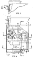
- Fig. 1 is a plan view, partially broken away, showing one embodiment of an original document handling apparatus in accordance with the present invention on a conventional copy machine body, partially broken away;
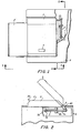
- Fig. 2 is a cross-sectional view taken along the line 2-2 of Fig. 1;
- Fig. 3 is a partially broken away side view otherwise viewed along the line 3-3 of Fig. 1;
- Fig. 4 is a broken away plan view of the original document handling apparatus;
- Fig. 5 is a sectional view taken along the line 5-5 of Fig. 4;
- Fig. 6 is a sectional view taken along the line 6-6 of Fig. 4;
- Fig. 7 is a sectional view taken along the line 7-7 of Fig. 4;
- Fig. 8 is a sectional view taken along the line 8-8 of Fig. 4;
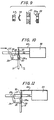
- Fig. 9 is an exploded cross-sectional view used to explain the structure of the over-running clutch;
- Figs. 10 and 11 are partial enlarged views showing the operation of the cam of the automatic releasing mechanism; and
- Fig. 12 is a circuit diagram of the logic circuit.
- One example of the present invention will now be described in more detail with reference to the accompanying above-identified drawings.
- As will be further explained herein, this exemplary original document handling apparatus disclosed in accordance with the present invention includes an opening and closing mechanism providing magnetic latching between the
copying machine body 6 and theplaten cover 7 and also automatic opening of theplaten cover 7 when the magnetic latch is released, operating in combination with an original document discharging mechanism A in theplaten cover 7 including aconveyor belt 14 for discharging the original document from the platen to the exterior; and a drive mechanism B therefor including helical spring driving means wound up, within limits, by movement of the platen cover during document loading or unloading. The discharging system A and its drive mechanism B are combined with an automatic releasing mechanism D in the platen cover for releasing the magnetic latch between thecopying machine body 6 and theplaten cover 7. A logic operation circuit including a solenoid release system and a connecting timing circuit controls the operation of both the original document discharging mechanism A and the automatic platen cover releasing mechanism D. The disclosed system is simple and inexpensive and can automatically discharge the original document from the platen after the copying operation is completed, reliably handling various kinds of original documents without damage thereto. - The disclosed embodiment is common in several respects to the document assist device disclosed in U.S. Patent No. 3,888,582. However, the present invention is not limited in application to this embodiment.
- As shown in Figs. 1 and 2 a conventional
copying machine body 6 pivotally supports asupport shaft 5 along the rear of theplaten cover 7 which is rotatably attached to a bracket on thecopy machine body 6. Anarm 40 is fixed to one end of thesupport shaft 5. Abracket 6b is fixed to thecopying machine body 6 to support arod 3a for reciprocating movement. Therod 3a is connected to thearm 40. Therod 3a has at one end a nut 3b and aspring stopper 3c. Abalance spring 3 is interposed between thespring stopper 3c and thebracket 6b. - The
platen cover 7 is formed at its front portion with ahandle 39 and provided in the vicinity of, and in parallel to, thehandle 39 with anelongated start switch 4 so that the machine operator can readily depress thestart switch 4 while closing theplaten cover 7 with one hand. The copying operation of the original document on the platen is started by actuation of thestart switch 4 in the same manner as that of the conventional print switch (not shown) provided on the control board or console of thecopying machine body 6. However, thestart switch 4 is different from that print switch on thecopying machine body 6 in that it additionally starts the following described operations at the end of the copying operation, including ejecting the original documents into an originaldocument receiving tray 2 provided on the copying machine body 6 (note Fig. 3). - As shown particularly in Figs. 4, 5 and 7, an original document discharging mechanism A is provided substantially centrally in the
platen cover 7. As shown in Fig. 7, it includesshafts respective brackets 7a and 7b of theplaten cover 7. Theshafts respective pulleys conveyor belt 14 is journaled. Apulley 16a is mounted on theshaft 15a as shown in Fig. 4. Theconveyor belt 14 extends centrally across the platen but it is much narrower. As shown in Fig. 6, it extends through and below a slot in thelower surface 43 of the platen cover. Thesurface 43 is slightly spaced above theplaten 35. - As shown, for example, in Fig. 4, a drive mechanism B is also provided in the
platen cover 7, for driving the original document discharging mechanism A, which includes helical spring means 18. The inner or internal end of thehelical spring 18 is engaged with ashaft 17 having thereon a pulley 16b. Atiming belt 16 is journaled around thepulleys 16a and 16b to drivably connectshafts 1 5a and 17. Ahub 20 is mounted to theshaft 17. Apulley 21 is adjacently rotatably mounted on theshaft 17 through an over-runningclutch 60 shown exploded in Fig. 9. That is, theshaft 17 has thereon aleaf spring 36 and aring 37 so that thepulley 21 is releasably attached to thehub 20. As shown in Figs. 4 and 5, aguide pulley 22 is provided in theplaten cover 7. Anarm 24 is secured on thesupport shaft 5 and apulley 23 is mounted on thecopying machine body 6. A wire orcord 34 having one end attached to thearm 24 extends through thepulley 23 and theguide pulley 22 to thepulley 21. - A stopper or escapement mechanism C, as shown in Figs. 4 and 8, is drivingly connected to the helical spring means 18. It is in the
platen cover 7 and includes aratchet 19 drivingly connected to thehelical spring 18. Apawl 41 engages theratchet 19. Thepawl 41 is pivotally mounted by apin 38 to a bracket 7e of theplaten cover 7 and is normally biased by aspring 25 into engagement with theratchet 19 to allow winding, but prevent unwinding ofspring 18. Asolenoid 33 is provided in the platen cover to operate arod 26 which has its end connected tospring 25 andratchet 19 to releasepawl 41 when thesolenoid 33 is actuated againstspring 25. - Provided at the front end of the
platen cover 7 is a permanent magnet 11 slightly projecting from thelower surface 43 and anattraction plate 10 mounted to thecopying machine body 6. The magnet 11 is attracted to theattraction plate 10 so as to provide magnetic latching between theplaten cover 7 and thecopying machine body 6. Since the magnet 11 is located on the front end of theplaten cover 7, furthest from the center of rotation of theplaten cover 7, the magnet 11 has the maximum leverage to hold theplaten cover 7 closed against the force of thecounterbalance spring 3 tending to lift theplaten cover 7. However, the force of thespring 3 lifts theplaten cover 7 automatically when the machine operator slightly lifts theplaten cover 7 so as to separate the magnet 11 from theattraction plate 10. - An automatic opening mechanism D is provided in the
platen cover 7, which includes acam 9 rockably mounted to thebracket 7f of theplaten cover 7 by means of apin 42. One end of ashaft 31 is attached to thecam 9 for pivotal movement and movably supported by asupport member 31 a of theplaten cover 7. As enlarged in Figs. 10 and 11, acam 28 is pivotally mounted by apin 29 on theplaten cover 7, and thiscam 28 is formed with an elongated hole or slot 28a. Apin 30 is secured on the other end ofshaft 31 and is engaged by the slot 28a. Thecam 28 is biased by aspring 32 in the counter-clockwise direction. - A logic operation circuit mounting 13 is provided in the
platen cover 7 which contains a logic operation and timing circuit as shown in Fig. 12, including a latch circuit 45, atimer circuit 46, a timer start latch circuit 47, a power common orground 48, aninput 49 from a ready lamp, aninput 50 from the copier run relay, aninput 51 from thestart switch 4, andoutput 52 to thesolenoid 33, and anoutput 53 to the print switch provided on the copying machine body. - Pressing the
start switch 4 sets the copying machine in operation. When the copying operation is completed, a copying operation end signal is delivered from the ready lamp. The copying machine produces anothersignal 50 from the run relay which is an inhibit signal for preventing the operation of the original document discharging apparatus of the present invention except during the copying operation. - A brief description of the operation of the circuit shown in Fig. 12 is as follows: When the
start switch 4 provided on theplaten cover 7 is depressed, a copying operation start signal is produced and simultaneously the latch circuit 45 is set so as to set in its ready state the timer start latch circuit 47 for thetimer circuit 46. When the copying operation is completed and the ready lamp goes on, the timer start latch circuit 47 is actuated so as to energize thesolenoid 33. The time thesolenoid 33 is held energized is pre-determined by a timer 555 and after that pre-determined time passes thesolenoid 33 is de-energized and also the timerstart latch circuit 42 and thelatch circuit 46 return to their initial state in accordance with the output from the timer. If the print switch provided on the copying machine body is depressed the latch circuit 45 is not set and thus thetimer circuit 46 remains non-operable so that thesolenoid 33 remains de-energized. - The operation of the present system will now be further described. The machine operator opens the
platen cover 7, if it is closed, by grasping thehandle 39 and places the first original document to be copied in position on the platen. Then he or she closes theplaten cover 7 and simultaneously depresses thestart switch 4 to start the copying operation of the original document on the platen. No further operator action is required. After a pre-determined number of copies are produced from the original document, the original document is automatically discharged from the platen to the originaldocument output tray 2 and theplaten cover 7 is automatically lifted so that the next document can be placed on the platen. This is repeated for any subsequent documents to be copied. - The operation of automatically discharging the original document after the copying operation is completed is as follows: The
logic circuit 13 responds to the copy operation end signal to energize thesolenoid 33 as described above. This causes therod 26 to move to the right so as to rotate thepawl 41 in the clockwise direction, whereby the engagement between thepawl 41 and theratchet 19 is released and thus thehelical spring 18 is freed. The length of time thesolenoid 33 is held energized is controlled by thetimer circuit 46 such that theconveyor belt 14 can completely discharge the original document on the platen, driven by thespring 18. When thehelical spring 18 is so freed, it rotates theshaft 17, and theshaft 15a is rotated through the pulley 16b and thetiming belt 16 and thepulley 16a to drive theconveyor belt 14 thereby discharging the original document from the platen to the originaldocument output tray 2. - The
helical spring 18 would be gradually unwound or loosened with repeated such operations, and eventually would not be able to provide the driving force to theconveyor belt 14, unless it was rewound. This is accomplished by the opening motion of theplaten cover 7, which causes movement of thearm 24 to the position indicated by the dashed line in Fig. 5 and pulls thewire 34. Thepulley 21 is rotated through thepulleys wire 34 so as to wind up the helical spring. - Preferably the full loading of the
spring 18 is effected by a partial opening of theplaten cover 7 since the platen cover is often not completely opened by the operator. In order to protect thehelical spring 18 and the spring winding mechanism against damage anover-winding protection clutch 60 is provided. Thewire 34 engagespulley 21 at an angle, to apply axial as well as rotational force. When thehelical spring 18 is wound up and the load torque of theshaft 17 and the tension onwire 34 becomes large, axial movement of thepulley 21 compresses theleaf spring 36 and releases the engagement between theprojection 20a of thehub 20 and a normally mating recess in thepulley 21, all as shown in Fig. 9, whereby thepulley 21 is freed to slip over thestationary hub 20. - It will be appreciated that a regular spring loaded frictional slip clutch could be used instead, in which case the
wire 34 could wrap normally on thepulley 21, by repositioningpulley 22. - The automatic opening operation of the
platen cover 7 is as follows: As shown in Fig. 10, when thesolenoid 33 is energized, therod 26 moves to the right so as to bring itspin 27 into contact with the projection of thecam 28 thereby rotating thecam 28 about itssupport shaft 29 in the clockwise direction. However, when thecam 28 is rotated in that direction its movement cannot be transmitted to pin 30, due to slot 28a, and with further movement of thesolenoid 33 thepin 27 is released from (passes) the projection of thecam 28 so as to establish the relationship shown in Fig. 11. As noted above, when thesolenoid 33 is energized, thepawl 41 also parts from theratchet 19 to loosen thehelical spring 18 so as to rotate theconveyor belt 14 thereby discharging the original document from the platen. The time required to discharge the original document is pre-determined in thelogic operation circuit 13 and thesolenoid 33 is de-energized after that time passes. - When the
solenoid 33 is de-energized, thepawl 41 and theratchet 19 are engaged again by the force of thespring 25 so as to stop the rotation of theconveyor belt 14. Further, therod 26 is moved to the left by the force of thespring 25 so as to again come into contact with the projection of thecam 28, but from the opposite direction. This causes thecam 28 to now rotate in the opposite or counter-clockwise direction so as to pull theshaft 31 through thepin 30 engaged with the end of the slot 28a, thereby rocking thecam 9 to lift theplaten cover 7. As a result, the magnetic lock between the magnet 11 and theplate 10 is released and thus theplaten cover 7 is automatically opened by the force of thebalance spring 3. When thesolenoid 33 is completely de-energized, thepin 27 passes out of contact from the projection of thecam 28 and returns to the position shown in Fig. 10.
Claims (6)
Applications Claiming Priority (2)
| Application Number | Priority Date | Filing Date | Title |
|---|---|---|---|
| JP28462/78 | 1978-03-08 | ||
| JP1978028462U JPS54133856U (en) | 1978-03-08 | 1978-03-08 |
Publications (2)
| Publication Number | Publication Date |
|---|---|
| EP0004162A1 EP0004162A1 (en) | 1979-09-19 |
| EP0004162B1 true EP0004162B1 (en) | 1982-06-02 |
Family
ID=12249317
Family Applications (1)
| Application Number | Title | Priority Date | Filing Date |
|---|---|---|---|
| EP79300311A Expired EP0004162B1 (en) | 1978-03-08 | 1979-03-01 | Document handling apparatus for a copier |
Country Status (5)
| Country | Link |
|---|---|
| US (1) | US4190359A (en) |
| EP (1) | EP0004162B1 (en) |
| JP (1) | JPS54133856U (en) |
| CA (1) | CA1122259A (en) |
| DE (1) | DE2962982D1 (en) |
Families Citing this family (13)
| Publication number | Priority date | Publication date | Assignee | Title |
|---|---|---|---|---|
| US4295731A (en) * | 1978-04-17 | 1981-10-20 | Mita Industrial Company Limited | Electrostatic copying apparatus |
| US4299478A (en) * | 1979-10-30 | 1981-11-10 | Xerox Corporation | Bound document apparatus for a copier |
| US4367947A (en) * | 1981-05-20 | 1983-01-11 | International Business Machines Corporation | Document feeder for moving bed machines such as copiers |
| US4368977A (en) * | 1981-05-20 | 1983-01-18 | International Business Machines Corporation | Document ejector apparatus and method useful for copiers |
| USH43H (en) | 1984-12-03 | 1986-04-01 | Xerox Corporation | Magnetic latch closure control |
| US4721981A (en) * | 1986-11-03 | 1988-01-26 | Xerox Corporation | Low-cost document feeder for copiers |
| US5110103A (en) * | 1988-07-12 | 1992-05-05 | Mita Industrial Co., Ltd. | Image forming apparatus with improved document feeder |
| JP2709967B2 (en) * | 1989-11-28 | 1998-02-04 | 三田工業株式会社 | Automatic document feeder |
| US5365309A (en) * | 1993-08-17 | 1994-11-15 | Colight, A Division Of Hanovia Lamp | Exposure frame assembly |
| US6318437B1 (en) * | 1998-07-09 | 2001-11-20 | Samsung Aerospace Industries, Ltd. | Tape feeder for component part mounter |
| TWI278223B (en) * | 2005-09-20 | 2007-04-01 | Benq Corp | Scanner |
| AU2011258203A1 (en) | 2010-05-26 | 2013-01-10 | The Charles Stark Draper Laboratory, Inc. | Microfabricated artificial lung assist device, and methods of use and manufacture thereof |
| JP6112669B2 (en) * | 2013-05-20 | 2017-04-12 | トヨフレックス株式会社 | Hinge device |
Family Cites Families (9)
| Publication number | Priority date | Publication date | Assignee | Title |
|---|---|---|---|---|
| US3467469A (en) * | 1966-10-17 | 1969-09-16 | Dennison Mfg Co | Cover for photocopiers |
| US3623806A (en) * | 1969-10-20 | 1971-11-30 | Minnesota Mining & Mfg | Original document feeder with registering gate and movable platen |
| US3726589A (en) * | 1971-11-05 | 1973-04-10 | Eastman Kodak Co | Convertible document feeder and flexible light shield |
| US3994582A (en) * | 1973-10-05 | 1976-11-30 | Canon Kabushiki Kaisha | Original keep device in copying machine |
| US3888582A (en) * | 1974-03-08 | 1975-06-10 | Xerox Corp | Semi-automatic document handler |
| US3888585A (en) * | 1974-03-08 | 1975-06-10 | Xerox Corp | Semi-automatic document handler |
| JPS5234719A (en) * | 1975-09-12 | 1977-03-16 | Fuji Xerox Co Ltd | Document take-out device |
| GB1529696A (en) * | 1975-10-24 | 1978-10-25 | Xerox Corp | Document handling apparatus |
| US4030721A (en) * | 1976-07-27 | 1977-06-21 | Rank Xerox Ltd. | Automatic manuscript discharging device for copying machines |
-
1978
- 1978-03-08 JP JP1978028462U patent/JPS54133856U/ja active Pending
- 1978-12-21 US US05/972,162 patent/US4190359A/en not_active Expired - Lifetime
-
1979
- 1979-02-20 CA CA000321879A patent/CA1122259A/en not_active Expired
- 1979-03-01 DE DE7979300311T patent/DE2962982D1/en not_active Expired
- 1979-03-01 EP EP79300311A patent/EP0004162B1/en not_active Expired
Also Published As
| Publication number | Publication date |
|---|---|
| DE2962982D1 (en) | 1982-07-22 |
| JPS54133856U (en) | 1979-09-17 |
| CA1122259A (en) | 1982-04-20 |
| EP0004162A1 (en) | 1979-09-19 |
| US4190359A (en) | 1980-02-26 |
Similar Documents
| Publication | Publication Date | Title |
|---|---|---|
| CA1122259A (en) | Copier document handling system | |
| JPH0146410B2 (en) | ||
| JPS592011B2 (en) | Document table reciprocating motion control device in electrostatic reproducing device | |
| US4374401A (en) | Tape player | |
| US3888582A (en) | Semi-automatic document handler | |
| JPH036371Y2 (en) | ||
| EP0296631A2 (en) | Apparatus for electrically operating a circit breaker | |
| JPS5952135B2 (en) | Switching tongue drive device in a letter transport device and switching device equipped with such a drive device | |
| GB2081827A (en) | Game devices; mechanism for resisting rotation | |
| US4112449A (en) | Stop motion device for motor driven device | |
| JP2500157B2 (en) | Lamp display for pachinko machine and control method thereof | |
| US6336751B1 (en) | Film feeding device, and optical apparatus including the same | |
| US4443209A (en) | Gaming apparatus having manually controllable-operating speed | |
| US4693579A (en) | Arrangement for winding cameras | |
| JPS5943555Y2 (en) | Copy machine automatic paper feeder | |
| JPH0619541B2 (en) | Film supply device | |
| JPS6210269Y2 (en) | ||
| JP3130885B2 (en) | Printing equipment | |
| EP0526144B1 (en) | Cassette recorders | |
| JPS6144202Y2 (en) | ||
| KR100230778B1 (en) | Reel braking device for vcr deck mechanism | |
| JP2645931B2 (en) | Automatic paper feeder clutch device | |
| JPS62200628A (en) | Apparatus for closing breaker | |
| KR900000989B1 (en) | Cassette eject device of cassette type tape recorder for car stereo | |
| JPH034529Y2 (en) |
Legal Events
| Date | Code | Title | Description |
|---|---|---|---|
| PUAI | Public reference made under article 153(3) epc to a published international application that has entered the european phase |
Free format text: ORIGINAL CODE: 0009012 |
|
| AK | Designated contracting states |
Designated state(s): DE GB NL |
|
| 17P | Request for examination filed | ||
| GRAA | (expected) grant |
Free format text: ORIGINAL CODE: 0009210 |
|
| AK | Designated contracting states |
Designated state(s): DE GB NL |
|
| REF | Corresponds to: |
Ref document number: 2962982 Country of ref document: DE Date of ref document: 19820722 |
|
| PGFP | Annual fee paid to national office [announced via postgrant information from national office to epo] |
Ref country code: DE Payment date: 19840111 Year of fee payment: 6 |
|
| PGFP | Annual fee paid to national office [announced via postgrant information from national office to epo] |
Ref country code: NL Payment date: 19840331 Year of fee payment: 6 |
|
| PG25 | Lapsed in a contracting state [announced via postgrant information from national office to epo] |
Ref country code: NL Effective date: 19851001 |
|
| NLV4 | Nl: lapsed or anulled due to non-payment of the annual fee | ||
| PG25 | Lapsed in a contracting state [announced via postgrant information from national office to epo] |
Ref country code: GB Effective date: 19890301 |
|
| GBPC | Gb: european patent ceased through non-payment of renewal fee | ||
| PG25 | Lapsed in a contracting state [announced via postgrant information from national office to epo] |
Ref country code: DE Effective date: 19891201 |
|
| PLBE | No opposition filed within time limit |
Free format text: ORIGINAL CODE: 0009261 |
|
| STAA | Information on the status of an ep patent application or granted ep patent |
Free format text: STATUS: NO OPPOSITION FILED WITHIN TIME LIMIT |