EP0004146B1 - Electrical connector comprising a crimping ferrule - Google Patents
Electrical connector comprising a crimping ferrule Download PDFInfo
- Publication number
- EP0004146B1 EP0004146B1 EP79300267A EP79300267A EP0004146B1 EP 0004146 B1 EP0004146 B1 EP 0004146B1 EP 79300267 A EP79300267 A EP 79300267A EP 79300267 A EP79300267 A EP 79300267A EP 0004146 B1 EP0004146 B1 EP 0004146B1
- Authority
- EP
- European Patent Office
- Prior art keywords
- metal sleeve
- crimping ferrule
- connector
- crimping
- sleeve
- Prior art date
- Legal status (The legal status is an assumption and is not a legal conclusion. Google has not performed a legal analysis and makes no representation as to the accuracy of the status listed.)
- Expired
Links
Images
Classifications
-
- H—ELECTRICITY
- H01—ELECTRIC ELEMENTS
- H01R—ELECTRICALLY-CONDUCTIVE CONNECTIONS; STRUCTURAL ASSOCIATIONS OF A PLURALITY OF MUTUALLY-INSULATED ELECTRICAL CONNECTING ELEMENTS; COUPLING DEVICES; CURRENT COLLECTORS
- H01R4/00—Electrically-conductive connections between two or more conductive members in direct contact, i.e. touching one another; Means for effecting or maintaining such contact; Electrically-conductive connections having two or more spaced connecting locations for conductors and using contact members penetrating insulation
- H01R4/10—Electrically-conductive connections between two or more conductive members in direct contact, i.e. touching one another; Means for effecting or maintaining such contact; Electrically-conductive connections having two or more spaced connecting locations for conductors and using contact members penetrating insulation effected solely by twisting, wrapping, bending, crimping, or other permanent deformation
- H01R4/18—Electrically-conductive connections between two or more conductive members in direct contact, i.e. touching one another; Means for effecting or maintaining such contact; Electrically-conductive connections having two or more spaced connecting locations for conductors and using contact members penetrating insulation effected solely by twisting, wrapping, bending, crimping, or other permanent deformation by crimping
- H01R4/20—Electrically-conductive connections between two or more conductive members in direct contact, i.e. touching one another; Means for effecting or maintaining such contact; Electrically-conductive connections having two or more spaced connecting locations for conductors and using contact members penetrating insulation effected solely by twisting, wrapping, bending, crimping, or other permanent deformation by crimping using a crimping sleeve
- H01R4/203—Electrically-conductive connections between two or more conductive members in direct contact, i.e. touching one another; Means for effecting or maintaining such contact; Electrically-conductive connections having two or more spaced connecting locations for conductors and using contact members penetrating insulation effected solely by twisting, wrapping, bending, crimping, or other permanent deformation by crimping using a crimping sleeve having an uneven wire-receiving surface to improve the contact
- H01R4/206—Electrically-conductive connections between two or more conductive members in direct contact, i.e. touching one another; Means for effecting or maintaining such contact; Electrically-conductive connections having two or more spaced connecting locations for conductors and using contact members penetrating insulation effected solely by twisting, wrapping, bending, crimping, or other permanent deformation by crimping using a crimping sleeve having an uneven wire-receiving surface to improve the contact with transversal grooves or threads
Definitions
- This invention relates to an electrical connector.
- an electrical connector which comprises an electrical terminal having a contact end and a crimping ferrule for connection to an electrical conductor, the crimping ferrule being received in a metal sleeve which extends beyond the end of the crimping ferrule in the direction away from the contact end of the terminal, the metal sleeve in turn being received in an outer sleeve of electrically insulating material.
- a bared end portion of the conductor of an insulated electrical conductor is inserted into the crimping ferrule of the terminal through the metal sleeve, with an insulated portion of the conductor positioned in the portion of the metal sleeve which extends beyond the crimping ferrule of the terminal.
- the crimping ferrule is then crimped on to the conductor through the overlying outer insulating sleeve and the metal sleeve, both of which are also permanently deformed by such crimping, and the portion of the metal sleeve which extends beyond the crimping ferrule is crimped about the insulation of the conductor through the overlying outer insulating sleeve which is also permanently deformed by this crimping.
- the metal sleeve serves to protect the conductor from bending stresses which would otherwise occur at the position where the conductor enters the crimping ferrule of the terminal.
- the terminal can be made, for example by stamping and forming, from relatively thin stock material whereby the contact end thereof can be given desirable spring properties, the metal sleeve serving to increase the thickness of metal at the crimping ferrule of the terminal, thereby to ensure reliable crimping of the terminal to the conductor.
- an electrical connector comprising an electrical terminal having a contact end and a crimping ferrule for connection to an electrical conductor, the crimping ferrule being received in a metal sleeve which extends beyond the end of the crimping ferrule in the direction away from the contact end of the terminal, the metal sleeve in turn being received in an outer sleeve of electrically insulating material, is characterised in that the metal sleeve is a seamless member having a relatively thick wall over the portion overlying the crimping ferrule, and a relatively thin wall over the portion extending beyond the end of the crimping ferrule.
- the connector of this invention has the advantage that the two portions of this metal sleeve inherently have the necessary characteristics to enable the connector to be easily and reliably crimped to an insulated conductor, while allowing the terminal to be of any desired form, for example stamped and formed from resilient sheet metal.
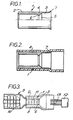
- Figure 1 shows a seamless circular cross-section metal sleeve 1 having a relatively thick wall portion 2 and a relatively thin wall portion 3.
- Such a metal sleeve can be formed by conventional metal working techniques.
- an intermediate portion 4 providing a funnel entry 5 from the portion 3 into the portion 2.
- the intermediate portion 4 also provides a shoulder 6 facing into the portion 2.
- the free end 7 of the portion 3 is flared outwardly to provide a funnel entry thereto.
- FIG 2 shows the metal sleeve 1 received in an outer sleeve 8 of electrically insulating plastics material, which outer sleeve 8 extends beyond the free end 7 of the portion 3 of the sleeve 1.
- Figure 3 shows the complete connector which includes an electrical terminal 9 having a receptacle contact end 10 for mating with a flat tab (not shown) and a crimping ferrule 11 of known form for connection to an electrical conductor, the crimping ferrule 11 being received in the portion 2 of the metal sleeve 1 with its insertion limited by the shoulder 6 therein.
- the insulation 12 is stripped from a portion at the end of an insulated electrical conductor 13, and the end portion is then inserted into the free end of the outer sleeve 8 with the end of the conductor 13 being guided into the crimping ferrule 11 by the funnel entry 5 of the metal sleeve 1, which funnel entry 5 also serves to limit insertion of the conductor by engagement of the insulation 12 on the conductor with the funnel entry 5.
- the crimping ferrule 11 is then crimped down on to the conductor 13 through the outer sleeve 8 and the portion 2 of the metal sleeve 1, and the portion 3 of the metal sleeve 1 can be crimped down on to the insulation 12 of the conductor through the outer sleeve 8, in known manner.
- the relatively thick wall of the portion 2 of the metal sleeve 1 ensures reliable crimping of the connector 1 on to the conductor 13 even when the material from which the terminal 9 is made is relatively thin as may be necessary to ensure the necessary spring properties for the receptacle end 10 thereof, while the relatively thin wall of the portion 3 of the metal sleeve 1 allows for easy crimping of this portion on to the insulation 12 of the conductor. Further, the absence of a seam in the metal sleeve 1 ensures that the metal sleeve 1 will not relax after crimping as could occur if the metal sleeve 1 had a longitudinally extending open seam as found in some known connectors.
Description
- This invention relates to an electrical connector.
- From U.S. Patent Specification No. 3,356,987 an electrical connector is known which comprises an electrical terminal having a contact end and a crimping ferrule for connection to an electrical conductor, the crimping ferrule being received in a metal sleeve which extends beyond the end of the crimping ferrule in the direction away from the contact end of the terminal, the metal sleeve in turn being received in an outer sleeve of electrically insulating material.
- For use of such a connector, a bared end portion of the conductor of an insulated electrical conductor is inserted into the crimping ferrule of the terminal through the metal sleeve, with an insulated portion of the conductor positioned in the portion of the metal sleeve which extends beyond the crimping ferrule of the terminal.
- The crimping ferrule is then crimped on to the conductor through the overlying outer insulating sleeve and the metal sleeve, both of which are also permanently deformed by such crimping, and the portion of the metal sleeve which extends beyond the crimping ferrule is crimped about the insulation of the conductor through the overlying outer insulating sleeve which is also permanently deformed by this crimping.
- After such crimping the metal sleeve serves to protect the conductor from bending stresses which would otherwise occur at the position where the conductor enters the crimping ferrule of the terminal. Further, with such a connector the terminal can be made, for example by stamping and forming, from relatively thin stock material whereby the contact end thereof can be given desirable spring properties, the metal sleeve serving to increase the thickness of metal at the crimping ferrule of the terminal, thereby to ensure reliable crimping of the terminal to the conductor.
- However, difficulties still arise with such connectors since if the metal sleeve is made sufficiently thick to ensure satisfactory crimping at the crimping ferrule, then it is often too thick for satisfactory crimping of the portion thereof overlying the conductor insulation to be easily carried out without damaging the conductor.
- According to this invention an electrical connector comprising an electrical terminal having a contact end and a crimping ferrule for connection to an electrical conductor, the crimping ferrule being received in a metal sleeve which extends beyond the end of the crimping ferrule in the direction away from the contact end of the terminal, the metal sleeve in turn being received in an outer sleeve of electrically insulating material, is characterised in that the metal sleeve is a seamless member having a relatively thick wall over the portion overlying the crimping ferrule, and a relatively thin wall over the portion extending beyond the end of the crimping ferrule.
- The connector of this invention has the advantage that the two portions of this metal sleeve inherently have the necessary characteristics to enable the connector to be easily and reliably crimped to an insulated conductor, while allowing the terminal to be of any desired form, for example stamped and formed from resilient sheet metal.
- An electrical terminal having an integrally formed sleeve comprising two axially aligned portions of mutually different wall thickness is disclosed in U.S. Patent Specification No. 3,844,923. However, this terminal is a machined member and is not a member stamped and formed from sheet metal. Further, this known terminal requires the use of a separate metal sleeve positioned inside the thicker wall portion of the integral sleeve of the terminal, and does not utilise an outer metal sleeve with an overlying insulating sleeve as found in the connector of this invention.
- An electrical connector according to this invention will now be described by way of example with reference to the drawings, in which:-
- Figure 1 is a side elevational view, partly in cross-section, of a metal sleeve of the connector;
- Figure 2 is a sectional plan view of the sleeve of Figure 1 received in an outer insulating sleeve of the connector; and
- Figure 3 is a plan view of the complete connector.
- Figure 1 shows a seamless circular cross-section metal sleeve 1 having a relatively
thick wall portion 2 and a relativelythin wall portion 3. Such a metal sleeve can be formed by conventional metal working techniques. - Between the
portions funnel entry 5 from theportion 3 into theportion 2. The intermediate portion 4 also provides ashoulder 6 facing into theportion 2. - The
free end 7 of theportion 3 is flared outwardly to provide a funnel entry thereto. - Referring now to Figure 2, this shows the metal sleeve 1 received in an
outer sleeve 8 of electrically insulating plastics material, whichouter sleeve 8 extends beyond thefree end 7 of theportion 3 of the sleeve 1. - Figure 3 shows the complete connector which includes an
electrical terminal 9 having areceptacle contact end 10 for mating with a flat tab (not shown) and acrimping ferrule 11 of known form for connection to an electrical conductor, thecrimping ferrule 11 being received in theportion 2 of the metal sleeve 1 with its insertion limited by theshoulder 6 therein. - For use of the connector, the
insulation 12 is stripped from a portion at the end of an insulatedelectrical conductor 13, and the end portion is then inserted into the free end of theouter sleeve 8 with the end of theconductor 13 being guided into thecrimping ferrule 11 by thefunnel entry 5 of the metal sleeve 1, whichfunnel entry 5 also serves to limit insertion of the conductor by engagement of theinsulation 12 on the conductor with thefunnel entry 5. The crimpingferrule 11 is then crimped down on to theconductor 13 through theouter sleeve 8 and theportion 2 of the metal sleeve 1, and theportion 3 of the metal sleeve 1 can be crimped down on to theinsulation 12 of the conductor through theouter sleeve 8, in known manner. - The relatively thick wall of the
portion 2 of the metal sleeve 1 ensures reliable crimping of the connector 1 on to theconductor 13 even when the material from which theterminal 9 is made is relatively thin as may be necessary to ensure the necessary spring properties for thereceptacle end 10 thereof, while the relatively thin wall of theportion 3 of the metal sleeve 1 allows for easy crimping of this portion on to theinsulation 12 of the conductor. Further, the absence of a seam in the metal sleeve 1 ensures that the metal sleeve 1 will not relax after crimping as could occur if the metal sleeve 1 had a longitudinally extending open seam as found in some known connectors.
Claims (4)
Applications Claiming Priority (2)
| Application Number | Priority Date | Filing Date | Title |
|---|---|---|---|
| GB911378 | 1978-03-08 | ||
| GB911378 | 1978-03-08 |
Publications (2)
| Publication Number | Publication Date |
|---|---|
| EP0004146A1 EP0004146A1 (en) | 1979-09-19 |
| EP0004146B1 true EP0004146B1 (en) | 1981-06-24 |
Family
ID=9865620
Family Applications (1)
| Application Number | Title | Priority Date | Filing Date |
|---|---|---|---|
| EP79300267A Expired EP0004146B1 (en) | 1978-03-08 | 1979-02-21 | Electrical connector comprising a crimping ferrule |
Country Status (12)
| Country | Link |
|---|---|
| EP (1) | EP0004146B1 (en) |
| JP (1) | JPS54126989A (en) |
| AR (1) | AR215222A1 (en) |
| AT (1) | AT370259B (en) |
| BR (1) | BR7901386A (en) |
| CA (1) | CA1098601A (en) |
| DE (1) | DE2960427D1 (en) |
| DK (1) | DK147520C (en) |
| ES (1) | ES478380A1 (en) |
| FI (1) | FI67156C (en) |
| MX (1) | MX144918A (en) |
| NO (1) | NO149014C (en) |
Families Citing this family (5)
| Publication number | Priority date | Publication date | Assignee | Title |
|---|---|---|---|---|
| US4953289A (en) * | 1989-06-05 | 1990-09-04 | Pyle Overseas B.V. | Conductor terminating method |
| DE19843886A1 (en) * | 1998-09-24 | 2000-03-30 | Grote & Hartmann | Cable shoe for electrical conductor wire or cable, has termination sleeve receiving stripped end of conductor wire or cable enclosed coaxially by reinforcing sleeve |
| DE19908031B4 (en) * | 1999-02-24 | 2009-08-13 | Auto-Kabel Management Gmbh | Connection of an electrical aluminum cable with a connector made of copper or the like metal |
| TWI307985B (en) * | 2006-03-31 | 2009-03-21 | Ks Terminals Inc | Electrical terminal connector and method of fabricating same |
| JP6522872B2 (en) * | 2013-02-22 | 2019-05-29 | 古河電気工業株式会社 | Crimp terminal, connection structure, connector, and method of manufacturing connection structure |
Family Cites Families (6)
| Publication number | Priority date | Publication date | Assignee | Title |
|---|---|---|---|---|
| FR925224A (en) * | 1944-07-28 | 1947-08-28 | British Insulated Callenders | Advanced terminal conductors for electric cables |
| GB885233A (en) * | 1957-06-04 | 1961-12-20 | Gen Electric Co Ltd | Improvements in or relating to connections between electric conductors |
| US2958723A (en) * | 1957-10-02 | 1960-11-01 | Thomas & Betts Corp | Electrical connector and sealing means therefor |
| US3356987A (en) * | 1966-08-10 | 1967-12-05 | Amp Inc | Insulation support and wire guide for an electrical connector |
| FR2048467A5 (en) * | 1969-06-09 | 1971-03-19 | Lucas Industries Ltd | |
| US3844923A (en) * | 1973-08-02 | 1974-10-29 | P Sandrock | Dangler assembly for electro-chemical installations |
-
1979
- 1979-02-12 NO NO790448A patent/NO149014C/en unknown
- 1979-02-20 CA CA321,867A patent/CA1098601A/en not_active Expired
- 1979-02-21 DE DE7979300267T patent/DE2960427D1/en not_active Expired
- 1979-02-21 EP EP79300267A patent/EP0004146B1/en not_active Expired
- 1979-02-26 AT AT0147679A patent/AT370259B/en not_active IP Right Cessation
- 1979-03-05 FI FI790742A patent/FI67156C/en not_active IP Right Cessation
- 1979-03-05 MX MX176795A patent/MX144918A/en unknown
- 1979-03-07 AR AR275734A patent/AR215222A1/en active
- 1979-03-07 JP JP2662579A patent/JPS54126989A/en active Pending
- 1979-03-07 BR BR7901386A patent/BR7901386A/en unknown
- 1979-03-07 DK DK94479A patent/DK147520C/en not_active IP Right Cessation
- 1979-03-07 ES ES478380A patent/ES478380A1/en not_active Expired
Also Published As
| Publication number | Publication date |
|---|---|
| DK147520C (en) | 1985-07-22 |
| NO790448L (en) | 1979-09-11 |
| FI67156C (en) | 1985-01-10 |
| JPS54126989A (en) | 1979-10-02 |
| MX144918A (en) | 1981-12-02 |
| NO149014B (en) | 1983-10-17 |
| ES478380A1 (en) | 1979-11-01 |
| DK94479A (en) | 1979-09-09 |
| ATA147679A (en) | 1982-07-15 |
| DK147520B (en) | 1984-09-10 |
| AR215222A1 (en) | 1979-09-14 |
| EP0004146A1 (en) | 1979-09-19 |
| NO149014C (en) | 1984-01-25 |
| BR7901386A (en) | 1979-10-02 |
| CA1098601A (en) | 1981-03-31 |
| FI790742A (en) | 1979-09-09 |
| FI67156B (en) | 1984-09-28 |
| DE2960427D1 (en) | 1981-10-01 |
| AT370259B (en) | 1983-03-10 |
Similar Documents
| Publication | Publication Date | Title |
|---|---|---|
| US5147230A (en) | Two piece electrical female terminal | |
| EP0739059B1 (en) | Coaxial connector | |
| EP0122700B1 (en) | Coaxial electrical connector for multiple outer conductor coaxial cable | |
| EP0001159B2 (en) | Electrical connector | |
| US4911660A (en) | Coaxial cable angle connector | |
| EP0000996A1 (en) | Electrical connector | |
| EP0279508A1 (en) | Electrical terminal | |
| EP0006297B1 (en) | Flag-type electrical terminal | |
| US5135417A (en) | Dual usage electrical/electronic pin terminal system | |
| US6837743B2 (en) | Cable end connector having good insulation function | |
| US5338233A (en) | Structure for electrically connecting a terminal and a wire | |
| EP0527399B1 (en) | Insulation displacement terminal | |
| US7118429B1 (en) | Electrical contact with wire trap | |
| EP0043655A1 (en) | Electrical terminal with a release member | |
| US5266046A (en) | Hermaphroditic electrical connection | |
| US4679887A (en) | Electrical terminal | |
| EP0704110B1 (en) | Insulated terminal with integral dual flared barrel | |
| EP0525249B1 (en) | Electrical connector and method of connecting shielded cable to same | |
| EP0210062B1 (en) | Electrical crimp connection | |
| EP0004146B1 (en) | Electrical connector comprising a crimping ferrule | |
| US4138188A (en) | Coaxial cable plug with center conductor as center contact | |
| EP0090538A2 (en) | Right angle coaxial connector | |
| JPH0572053U (en) | Wire crimp terminal | |
| EP0881717A3 (en) | Electric plug connector | |
| EP0555716B1 (en) | Insulated electrical terminal and method of fabricating same |
Legal Events
| Date | Code | Title | Description |
|---|---|---|---|
| PUAI | Public reference made under article 153(3) epc to a published international application that has entered the european phase |
Free format text: ORIGINAL CODE: 0009012 |
|
| AK | Designated contracting states |
Designated state(s): BE CH DE FR GB IT NL SE |
|
| 17P | Request for examination filed | ||
| ITF | It: translation for a ep patent filed |
Owner name: BARZANO' E ZANARDO MILANO S.P.A. |
|
| GRAA | (expected) grant |
Free format text: ORIGINAL CODE: 0009210 |
|
| AK | Designated contracting states |
Designated state(s): BE CH DE FR GB IT NL SE |
|
| REF | Corresponds to: |
Ref document number: 2960427 Country of ref document: DE Date of ref document: 19811001 |
|
| PGFP | Annual fee paid to national office [announced via postgrant information from national office to epo] |
Ref country code: CH Payment date: 19930205 Year of fee payment: 15 |
|
| ITTA | It: last paid annual fee | ||
| PG25 | Lapsed in a contracting state [announced via postgrant information from national office to epo] |
Ref country code: CH Effective date: 19940228 |
|
| REG | Reference to a national code |
Ref country code: GB Ref legal event code: 732E |
|
| REG | Reference to a national code |
Ref country code: CH Ref legal event code: PL |
|
| EAL | Se: european patent in force in sweden |
Ref document number: 79300267.6 |
|
| PGFP | Annual fee paid to national office [announced via postgrant information from national office to epo] |
Ref country code: NL Payment date: 19951231 Year of fee payment: 18 |
|
| PGFP | Annual fee paid to national office [announced via postgrant information from national office to epo] |
Ref country code: SE Payment date: 19960118 Year of fee payment: 18 |
|
| PGFP | Annual fee paid to national office [announced via postgrant information from national office to epo] |
Ref country code: BE Payment date: 19960312 Year of fee payment: 18 |
|
| PG25 | Lapsed in a contracting state [announced via postgrant information from national office to epo] |
Ref country code: SE Effective date: 19970222 |
|
| PG25 | Lapsed in a contracting state [announced via postgrant information from national office to epo] |
Ref country code: BE Effective date: 19970228 |
|
| BERE | Be: lapsed |
Owner name: AMP INC. (UNE SOC. DE PENNSYLVANIE) Effective date: 19970228 |
|
| PG25 | Lapsed in a contracting state [announced via postgrant information from national office to epo] |
Ref country code: NL Effective date: 19970901 |
|
| EUG | Se: european patent has lapsed |
Ref document number: 79300267.6 |
|
| NLV4 | Nl: lapsed or anulled due to non-payment of the annual fee |
Effective date: 19970901 |
|
| PGFP | Annual fee paid to national office [announced via postgrant information from national office to epo] |
Ref country code: GB Payment date: 19980108 Year of fee payment: 20 |
|
| PGFP | Annual fee paid to national office [announced via postgrant information from national office to epo] |
Ref country code: FR Payment date: 19980209 Year of fee payment: 20 |
|
| PGFP | Annual fee paid to national office [announced via postgrant information from national office to epo] |
Ref country code: DE Payment date: 19980227 Year of fee payment: 20 |
|
| PG25 | Lapsed in a contracting state [announced via postgrant information from national office to epo] |
Ref country code: GB Free format text: LAPSE BECAUSE OF EXPIRATION OF PROTECTION Effective date: 19990220 |
|
| REG | Reference to a national code |
Ref country code: GB Ref legal event code: PE20 Effective date: 19990220 |
|
| PLBE | No opposition filed within time limit |
Free format text: ORIGINAL CODE: 0009261 |
|
| STAA | Information on the status of an ep patent application or granted ep patent |
Free format text: STATUS: NO OPPOSITION FILED WITHIN TIME LIMIT |