EP0003853B1 - Process for continuously converting non-ferrous metal sulphide concentrates - Google Patents
Process for continuously converting non-ferrous metal sulphide concentrates Download PDFInfo
- Publication number
- EP0003853B1 EP0003853B1 EP79200059A EP79200059A EP0003853B1 EP 0003853 B1 EP0003853 B1 EP 0003853B1 EP 79200059 A EP79200059 A EP 79200059A EP 79200059 A EP79200059 A EP 79200059A EP 0003853 B1 EP0003853 B1 EP 0003853B1
- Authority
- EP
- European Patent Office
- Prior art keywords
- reactor
- oxygen
- ferrous metal
- lead
- phase
- Prior art date
- Legal status (The legal status is an assumption and is not a legal conclusion. Google has not performed a legal analysis and makes no representation as to the accuracy of the status listed.)
- Expired
Links
Images
Classifications
-
- C—CHEMISTRY; METALLURGY
- C22—METALLURGY; FERROUS OR NON-FERROUS ALLOYS; TREATMENT OF ALLOYS OR NON-FERROUS METALS
- C22B—PRODUCTION AND REFINING OF METALS; PRETREATMENT OF RAW MATERIALS
- C22B5/00—General methods of reducing to metals
- C22B5/02—Dry methods smelting of sulfides or formation of mattes
- C22B5/12—Dry methods smelting of sulfides or formation of mattes by gases
-
- Y—GENERAL TAGGING OF NEW TECHNOLOGICAL DEVELOPMENTS; GENERAL TAGGING OF CROSS-SECTIONAL TECHNOLOGIES SPANNING OVER SEVERAL SECTIONS OF THE IPC; TECHNICAL SUBJECTS COVERED BY FORMER USPC CROSS-REFERENCE ART COLLECTIONS [XRACs] AND DIGESTS
- Y02—TECHNOLOGIES OR APPLICATIONS FOR MITIGATION OR ADAPTATION AGAINST CLIMATE CHANGE
- Y02P—CLIMATE CHANGE MITIGATION TECHNOLOGIES IN THE PRODUCTION OR PROCESSING OF GOODS
- Y02P10/00—Technologies related to metal processing
- Y02P10/20—Recycling
Definitions
- the invention relates to a process for the continuous conversion of non-ferrous metal sulfide concentrates into a liquid non-ferrous metal-rich phase and a slag phase in an elongated, lying reactor, under a gas atmosphere containing zones of SO Z , sulfidic concentrates of copper, nickel, antimony, cobalt and Lead or their mixtures and additives are charged onto the melt, oxidizing and reducing gases are blown into the melt, the non-ferrous metal-rich phase and a non-ferrous metal-poor slag phase are discharged at the opposite end of the reactor and the phases in countercurrent to one another in essentially continuously layered form Streams flow to the outlet ends, at least a portion of the oxygen is blown into the melt from below through a plurality of independently controlled nozzles distributed across the length of the oxidation zone of the reactor, the solid feed through a plurality of independently fed expensive and gradually fed into the reactor over a considerable length of the reactor, the gradient of melt oxygen activity is adjusted by choosing the local
- DE-B-24 17 978 describes a method according to the introduction.
- the gas atmosphere in the reactor is conducted in cocurrent to the direction of flow of the slag phase and the exhaust gas is discharged from the reactor at the outlet end of the non-ferrous slag phase.
- the process is also carried out autogenously.
- the invention has for its object to reduce the metal content of the slag phase even further, to improve the heat utilization in the reactor and to enable additional heating.
- the object is achieved according to the invention in that the gas atmosphere in the reactor is conducted in countercurrent to the flow direction of the slag phase and the exhaust gas is withdrawn from the reactor at the outlet end of the non-ferrous metal-rich phase.
- the waste gases can be discharged upwards or to the side both through the end face of the reactor and near the end face.
- the process is controlled with respect to the control of the gradient of the oxygen activity and the temperature in the melt as described in DE-B-24 17 978.
- the oxygen potential in the gas atmosphere is changed by the countercurrent flow of the slag phase and the gas atmosphere, the oxygen potential and the SO 2 content being considerably reduced, in particular via the reduction zone.
- the nozzles can be arranged side by side in several rows, so that the entire width of the melt is well gasified without the reactor having to be pivoted back and forth about its longitudinal axis.
- a preferred embodiment is that fuels are blown into the melt at least in the reduction zone, the oxygen partial pressure in the gas atmosphere above the reduction zone is kept below 10- 3 bar, preferably below 10- 8 bar, and no SO 2 as protective gas in the reduction zone is blown in.
- the fuel can be liquid, gaseous or solid. Its combustion is controlled so that on the one hand the required heat is generated and on the other hand the required reduction conditions in the melt and in the gas phase are maintained.
- the protective gas for the nozzles can be hydrocarbons, which are then used as fuel, or inert gases, such as nitrogen. In the oxidation zone, as described in DE-B-24 17 978, S0 2 can be used as a protective gas.
- a preferred embodiment is that a calming zone is connected between the reduction zone and the oxidation zone, into which no gas is blown into the melt. This achieves a good separation of the gas atmosphere in the reduction zone and the oxidation zone, individual temperature control is possible in both stages, and the sulfide-rich metal phase is separated from the metal-rich slag phase in the calming zone, as a result of which a low sulfide activity is achieved in the reduction zone.
- a preferred embodiment is that when processing sulfidic lead or antimony concentrates, the lead or antimony sulfide contained in the fly dust in the exhaust pipe and / or exhaust gas cooling by admixing oxygen-containing gases at temperatures of 950 to 450 ° C predominantly to lead sulfate or antimony oxide and Antimony sulfate is oxidized, and the separated fly dust is mixed with the lead or antimony concentrate in an amount of 10 to 30% by weight, based on the use, and possibly with the addition of other metal sulfate-containing substances.
- the admixture of the oxidized flue dust causes a reaction with the sulfidic concentrates even at relatively low temperatures, without additional oxygen having to be added. The rapid turnover reduces the evaporation losses of metals. Close contact of the feed components is important.
- a preferred embodiment is that the concentrates and any additives are compacted before use in the reactor.
- the contact of the concentrates with the additives such as lime, Si0 2 , iron oxide, recycled flying dust and possibly other metal sulfate-containing substances and carbon, is particularly close.
- the compacting can take place, for example, by rolling, pelleting or pressing.
- the moist, compacted particles quickly fall through the gas atmosphere and the reaction takes place in the melt. The temperature rises slowly due to the moisture of the particles, so that the evaporation losses are kept low.
- the invention is explained in more detail and, for example, with reference to the figure and examples.
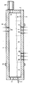
- the figure shows schematically a cross section through a reactor.
- the reactor 1 has the shape of a long furnace with a rounded cross section.
- the slag drain 2 is arranged in the left end face and the rack 3 for the non-ferrous metal-rich phase is arranged near the right end face.
- In the left end face there is an opening 4 which can be used as a work door or in which a burner can be arranged.
- the gas outlet opening 5, which opens into the exhaust gas duct 6, and an emergency tapping 7 are arranged in the right end side.
- the reactor 1 is divided into the working zone A, reduction zone R, calming zone B, oxidation zone O and quiet zone M, the transitions not being sharply delimited but are fluent.
- Charging openings 8 and nozzles 9 are arranged in the oxidation zone O, only a few of which are shown schematically.
- Nozzles 10 are also arranged in the reduction zone R, only a few of which are shown schematically.
- the reactor 1 is mounted on races 11 and can be rotated for maintenance.
- Lead concentrates were processed in a test reactor 4.8 m long and 1.8 m in diameter (external dimensions).
- the limited length of the reactor does not allow continuous operation with counter-current of lead, slag and exhaust gas. Therefore, the two most important process steps were carried out: 1) partial oxidation of the concentrate mixed with aggregates and fly dust to pelletized lead and a PbO-rich slag by blowing oxygen into the melt and 2) reduction of the PbO of the slag by introducing reducing agents in succession .
- the advantages of the invention are that the metal content of the slag phase is substantially reduced by controlling the composition of the gas phase and the temperature in the reduction zone and sulfidation of the resulting metals is prevented.
- metals whose sulfides have low volatility it is also imperative to maintain a low oxygen potential in the reduction zone, but it can be advantageous to set such a high S0 2 partial pressure that metal sulfides are formed during the reduction, which are considerable have lower solubility in the slag than metals.
- the heat utilization is significantly improved because the heat content of the gases from the reduction zone, which must be as high as possible for metallurgical reasons and in which an excess of reducing agent must be offered, can be largely utilized in the oxidation zone. It is possible, particularly with low-sulfur and low-iron concentrates, to introduce the necessary heat in an economical manner without disturbing the low oxygen potential required for the reduction.
Description
Die Erfindung betrifft ein Verfahren zur kontinuierlichen Konvertierung von NE-Metallsulfidkonzentraten in eine flüssige NE-metallreiche Phase und eine Schlackenphase in einem länglichen, liegenden Reaktor, unter einer zonenweise SOZ-enthaltenden Gasatmosphäre, wobei sulfidische Konzentrate von Kupfer, Nickel, Antimon, Kobalt und Blei oder deren Mischungen und Zuschläge auf die Schmelze chargiert werden, oxydierende und reduzierende Gase in die Schmelze eingeblasen werden, die NE-metallreiche Phase und eine NE-metallarme Schlackenphase am entgegengesetzten Ende des Reaktors ausgetragen und die Phasen in Gegenstrom zueinander in im wesentlichen kontinuierlich schichtförmigen Strömen zu den Auslaßenden fließen, mindestens ein Teil des Sauerstoffs durch eine Mehrzahl von unabhängig voneinander gesteuerten und über die Länge der Oxydationszone des Reaktors verteilten Düsen in die Schmelze von unten eingeblasen wird, die feste Beschickung durch eine Mehrzahl von unabhängig voneinander gesteuerten und über eine beträchtliche Länge des Reaktors verteilten Beschickungsvorrichtungen stufenweise in den Reaktor chargiert wird, der Gradient der Sauerstoffaktivität in der Schmelze durch Wahl der örtlichen Zugabe und Steuerung der Mengen des eingeführten Sauerstoffs und festen Materials so eingestellt wird, daß er von einem Maximum für die Erzeugung von NE-metallreichem und eisenarmen Material an dessen Auslaßende in fortschreitender Folge in der Reduktionszone bis zu einem Minimum für die Erzeugung von NE-metallarmer Schlackenphase an deren Auslaßende abnimmt, mit dem Sauerstoff gasförmige und/ oder flüssige Schutzmedien in gesteuerten Mengen zum Schutz der Düsen und der umgebenden Auskleidung und zur Hilfe für die Steuerung der Prozeßtemperatur in die Schmelze eingeblasen wird, und die in die Schmelze eingeblasenen Gasmengen so geregelt werden, daß eine für einen guten Stoffaustausch ausreichende Turbulenz im Bad entsteht, ohne daß die schichtförmige Strömung der Phasen und der Gradient der Sauerstoffaktivität im wesentlichen gestört wird.The invention relates to a process for the continuous conversion of non-ferrous metal sulfide concentrates into a liquid non-ferrous metal-rich phase and a slag phase in an elongated, lying reactor, under a gas atmosphere containing zones of SO Z , sulfidic concentrates of copper, nickel, antimony, cobalt and Lead or their mixtures and additives are charged onto the melt, oxidizing and reducing gases are blown into the melt, the non-ferrous metal-rich phase and a non-ferrous metal-poor slag phase are discharged at the opposite end of the reactor and the phases in countercurrent to one another in essentially continuously layered form Streams flow to the outlet ends, at least a portion of the oxygen is blown into the melt from below through a plurality of independently controlled nozzles distributed across the length of the oxidation zone of the reactor, the solid feed through a plurality of independently fed expensive and gradually fed into the reactor over a considerable length of the reactor, the gradient of melt oxygen activity is adjusted by choosing the local addition and control of the amounts of oxygen and solid material introduced so that it is of a maximum for the Production of non-ferrous metal-rich and low-iron material at the outlet end progressively decreases in the reduction zone to a minimum for the production of non-ferrous metal slag phase at the outlet end, with which oxygen gaseous and / or liquid protective media in controlled amounts to protect the nozzles and the surrounding lining and to aid in controlling the process temperature is blown into the melt, and the amounts of gas blown into the melt are regulated in such a way that sufficient turbulence is created in the bath for a good mass transfer without the layered flow of the phases and d he gradient of oxygen activity is essentially disturbed.
In der DE-B-24 17 978 ist ein Verfahren gemäß der Einleitung beschrieben. Bei diesem Verfahren wird die Gasatmosphäre im Reaktor im Gleichstrom zu der Strömungsrichtung der Schlakkenphase geführt und das Abgas am Auslaßende der NE-metallarmen Schlackenphase aus dem Reaktor abgeleitet. Außerdem wird das Verfahren autogen durchgeführt.DE-B-24 17 978 describes a method according to the introduction. In this process, the gas atmosphere in the reactor is conducted in cocurrent to the direction of flow of the slag phase and the exhaust gas is discharged from the reactor at the outlet end of the non-ferrous slag phase. The process is also carried out autogenously.
Der Erfindung liegt die Aufgabe zugrunde, den Metallgehalt der Schlackenphase noch weiter zu senken, die Wärmeausnutzung im Reaktor zu verbessern und eine Zusatzbeheizung zu ermöglichen.The invention has for its object to reduce the metal content of the slag phase even further, to improve the heat utilization in the reactor and to enable additional heating.
Die Lösung der Aufgabe erfolgt erfindungsgemäß dadurch, daß die Gasatmosphäre im Reaktor im Gegenstrom zu der Strömungsrichtung der Schlackenphase geführt und das Abgas am Auslaßende der NE-metallreichen Phase aus dem Reaktor abgezogen wird. Die Abgase können sowohl durch die Stirnseite des Reaktors als auch nahe der Stirnseite nach oben oder seitlich abgeführt werden. Der Prozeß wird im Hinblick auf die Steuerung des Gradienten der Sauerstoffaktivität und der Temperatur in der Schmelze so gesteuert, wie es in der DE-B-24 17 978 beschrieben ist. Das Sauerstoffpotential in der Gasatmosphäre wird jedoch durch die Gegenstromführung von Schlackenphase und Gasatmosphäre verändert, wobei insbesondere über der Reduktionszone das Sauerstoffpotential und der SO2-Gehalt erheblich verringert werden. Die Düsen können in mehreren Reihen nebeneinander angeordnet werden, so daß die gesamte Breite der Schmelze gut durchgast wird, ohne daß ein Hin- und Herschwenken des Reaktors um seine Längsachse erforderlich ist.The object is achieved according to the invention in that the gas atmosphere in the reactor is conducted in countercurrent to the flow direction of the slag phase and the exhaust gas is withdrawn from the reactor at the outlet end of the non-ferrous metal-rich phase. The waste gases can be discharged upwards or to the side both through the end face of the reactor and near the end face. The process is controlled with respect to the control of the gradient of the oxygen activity and the temperature in the melt as described in DE-B-24 17 978. However, the oxygen potential in the gas atmosphere is changed by the countercurrent flow of the slag phase and the gas atmosphere, the oxygen potential and the SO 2 content being considerably reduced, in particular via the reduction zone. The nozzles can be arranged side by side in several rows, so that the entire width of the melt is well gasified without the reactor having to be pivoted back and forth about its longitudinal axis.
Eine vorzugsweise Ausgestaltung besteht darin, daß mindestens in der Reduktionszone Brennstoffe in die Schmelze eingeblasen werden, der Sauerstoffpartialdruck in der Gasatmosphäre über der Reduktionszone unter 10-3 bar, vorzugsweise unter 10-8 bar, gehalten wird und kein S02 als Schutzgas in die Reduktionszone eingeblasen wird. Der Brennstoff kann flüssig, gasförmig oder fest sein. Seine Verbrennung wird so gesteuert, daß einerseits die erforderliche Wärme erzeugt und andererseits die erforderlichen Reduktionsbedingungen in der Schmelze und in der Gasphase eingehalten werden. Als Schutzgas für die Düsen können Kohlenwasserstoffe dienen, die danach selbst als Brennstoff verwendet werden, oder Inertgase, wie z.B. Stickstoff. In der Oxidationszone kann, wie in der DE-B-24 17 978 beschrieben, S02 als Schutzgas verwendet werden. Durch das Einblasen des Brennstoffes unmittelbar in die Schmelze wird eine gute Wärmeübertragung auf das Schmelzgut und damit eine hohe Brennstoffausnutzung bei niedrigen Temperaturen des Reaktorgewölbes erreicht. Bei der Verarbeitung von Bleikonzentraten werden bereits bei einem Sauerstoffpartialdruck von 10-3 bar in der Gasatmosphäre gute Ergebnisse erzielt. Diese Ergebnisse verbessern sich mit geringerem Sauerstoffpartialdruck. Für die Verarbeitung von Kupferkonzentraten muß der Sauerstoffpartialdruck unter 10-8 bar liegen. Bei dieser Arbeitsweise gelingt es, innerhalb weiter Grenzen die physikalisch-chemisch günstigsten Temperaturen und Bedingungen in jeder Ofenzone einzustellen. Falls die Zufuhr von weiterer Wärme erforderlich ist, insbesondere bei Konzentraten mit geringerem Schwefelgehalt, kann ein Brenner an der Stirnseite der Reduktionszone angeordnet werden und/oder Brennstoff durch Düsen oder zusammen mit der festen Beschickung in die Oxidationszone eingebracht werden. Der Brenner muß so betrieben werden, daß das erforderliche Sauerstoffpotential in der Gasphase eingehalten wird.A preferred embodiment is that fuels are blown into the melt at least in the reduction zone, the oxygen partial pressure in the gas atmosphere above the reduction zone is kept below 10- 3 bar, preferably below 10- 8 bar, and no SO 2 as protective gas in the reduction zone is blown in. The fuel can be liquid, gaseous or solid. Its combustion is controlled so that on the one hand the required heat is generated and on the other hand the required reduction conditions in the melt and in the gas phase are maintained. The protective gas for the nozzles can be hydrocarbons, which are then used as fuel, or inert gases, such as nitrogen. In the oxidation zone, as described in DE-B-24 17 978, S0 2 can be used as a protective gas. By blowing the fuel directly into the melt, good heat transfer to the material to be melted and thus high fuel utilization at low reactor vault temperatures are achieved. When processing lead concentrates, good results are already achieved in the gas atmosphere at an oxygen partial pressure of 10- 3 bar. These results improve with lower oxygen partial pressure. The oxygen partial pressure must be below 10- 8 bar for the processing of copper concentrates. With this method of operation it is possible to set the physically and chemically most favorable temperatures and conditions in each furnace zone within wide limits. If the supply of additional heat is required, particularly in the case of concentrates with a lower sulfur content, a burner can be arranged on the end face of the reduction zone and / or fuel can be introduced into the oxidation zone through nozzles or together with the solid feed. The burner must be operated that the required oxygen potential is maintained in the gas phase.
Eine vorzugsweise Ausgestaltung besteht darin, daß zwischen der Reduktionszone und der Oxidationszone eine Beruhigungszone geschaltet ist, in die kein Gas in die Schmelze eingeblasen wird. Dadurch wird eine gute Trennung der Gasatmosphäre in der Reduktionszone und der Oxidationszone erzielt, es ist eine individuelle Temperatursteuerung in beiden Stufen möglich, und in der Beruhigungszone erfolgt eine Trennung der sulfidreichen Metallphase von der metallreichen Schlackenphase, wodurch eine niedrige Sulfidaktivität in der Reduktionszone erreicht wird.A preferred embodiment is that a calming zone is connected between the reduction zone and the oxidation zone, into which no gas is blown into the melt. This achieves a good separation of the gas atmosphere in the reduction zone and the oxidation zone, individual temperature control is possible in both stages, and the sulfide-rich metal phase is separated from the metal-rich slag phase in the calming zone, as a result of which a low sulfide activity is achieved in the reduction zone.
Eine vorzugsweise Ausgestaltung besteht darin, daß bei der Verarbeitung von sulfidischen Blei- oder Antimonkonzentraten das im Flugstaub enthaltene Blei- oder Antimonsulfid in der Abgasleitung und/oder Abgaskühlung durch Zumischung von sauerstoffhaltigen Gasen bei Temperaturen von 950 bis 450 °C überwiegend zu Bleisulfat oder Antimonoxid und Antimonsulfat oxidiert, und der abgeschiedene Flugstaub mit dem Blei- oder Antimonkonzentrat in einer Menge von 10 bis 30 Gew.-%, bezogen auf den Einsatz, und eventuell unter Zusatz von anderen metallsulfathaltigen Stoffen gemischt wird. Die Zumischung der oxidierten Flugstäube bewirkt schon bei relativ niedrigen Temperaturen eine Reaktion mit den Sulfidischen Konzentraten, ohne daß dazu zusätzlicher Sauerstoff zugeführt werden muß. Der schnelle Umsatz verringert die Verdampfungsverluste von Metallen. Wichtig ist dabei ein enger Kontakt der Beschickungsbestandteile.A preferred embodiment is that when processing sulfidic lead or antimony concentrates, the lead or antimony sulfide contained in the fly dust in the exhaust pipe and / or exhaust gas cooling by admixing oxygen-containing gases at temperatures of 950 to 450 ° C predominantly to lead sulfate or antimony oxide and Antimony sulfate is oxidized, and the separated fly dust is mixed with the lead or antimony concentrate in an amount of 10 to 30% by weight, based on the use, and possibly with the addition of other metal sulfate-containing substances. The admixture of the oxidized flue dust causes a reaction with the sulfidic concentrates even at relatively low temperatures, without additional oxygen having to be added. The rapid turnover reduces the evaporation losses of metals. Close contact of the feed components is important.
Eine vorzugsweise Ausgestaltung besteht darin, daß die Konzentrate sowie eventuell Zuschlagstoffe vor dem Einsatz in den Reaktor kompaktiert werden. Dadurch wird der Kontakt der Konzentrate mit den Zuschlägen, wie Kalk, Si02, Eisenoxid, rückgeführter Flugstaub und eventuell andere metallsulfathaltige Stoffe und Kohlenstoff, besonders eng. Die Kompaktierung kann z.B. durch Rollieren, Pelletieren oder Pressen erfolgen. Die feuchten, kompaktierten Teilchen fallen schnell durch die Gasatmosphäre und die Reaktion erfolgt in der Schmelze. Durch die Feuchte der Teilchen steigt die Temperatur langsam an, so daß die Verdampfungsverluste gering gehalten werden.A preferred embodiment is that the concentrates and any additives are compacted before use in the reactor. As a result, the contact of the concentrates with the additives, such as lime, Si0 2 , iron oxide, recycled flying dust and possibly other metal sulfate-containing substances and carbon, is particularly close. The compacting can take place, for example, by rolling, pelleting or pressing. The moist, compacted particles quickly fall through the gas atmosphere and the reaction takes place in the melt. The temperature rises slowly due to the moisture of the particles, so that the evaporation losses are kept low.
Die Erfindung wird an Hand der Figur und von Beispielen näher und beispielsweise erläutert. Die Figur zeigt schematisch einen Querschnitt durch einen Reaktor.The invention is explained in more detail and, for example, with reference to the figure and examples. The figure shows schematically a cross section through a reactor.
Der Reaktor 1 hat die Form eines langen Ofens mit abgerundetem Querschnitt. In der linken Stirnseite ist der Schlackenablauf 2 und in der Nähe der rechten Stirnseite der Abstich 3 für die NE-metallreiche Phase angeordnet. In der linken Stirnseite ist eine Öffnung 4 angebracht, die als Arbeitstür benutzt werden kann oder in der ein Brenner angeordnet werden kann. In der rechten Stirnseite ist die Gasaustrittsöffnung 5 angeordnet, die in den Abgaskanal 6 mündet, sowie ein Notabstich 7. Der Reaktor 1 ist in die Arbeitszone A, Reduktionszone R, Beruhigungszone B, Oxidationszone O und Ruhezone M unterteilt, wobei die Übergänge nicht scharf begrenzt, sondern fließend sind. In der Oxidationszone O sind Chargieröffnungen 8 und Düsen 9 angeordnet, von denen nur einige schematisch dargestellt sind. In der Reduktionszone R sind ebenfalls Düsen 10 angeordnet, von denen nur einige schematisch dargestellt sind. Der Reaktor 1 ist auf Laufringen 11 gelagert und kann zur Wartung gedreht werden.The
In einem Versuchsreaktor mit 4,8 m Länge und 1,8 m Durchmesser (Außenmaße) wurden Bleikonzentrate verarbeitet. Die nur begrenzte Länge des Reaktors erlaubt noch keinen kontinuierlichen Betrieb mit Gegenstrom von Blei, Schlacke und Abgas. Deshalb wurden die beiden wesentlichsten Verfahrensschritte : 1) partielle Oxidation des mit Zuschlägen und Flugstaub gemischten und pelletierten Konzentrats zu metallischem Blei und einer PbO-reichen Schlacke durch Einblasen von Sauerstoff in die Schmelze und 2) Reduktion des PbO der Schlacke durch Einführung von Reduktionsmitteln nacheinander ausgeführt.Lead concentrates were processed in a test reactor 4.8 m long and 1.8 m in diameter (external dimensions). The limited length of the reactor does not allow continuous operation with counter-current of lead, slag and exhaust gas. Therefore, the two most important process steps were carried out: 1) partial oxidation of the concentrate mixed with aggregates and fly dust to pelletized lead and a PbO-rich slag by blowing oxygen into the melt and 2) reduction of the PbO of the slag by introducing reducing agents in succession .
1) Der Reaktor wurde mit einem Sauerstoff-Propan-Brenner auf eine Innentemperatur von 1100°C vorgeheizt. Sodann wurden durch die Brennertür 2,200 t Blei in Barren eingesetzt und eingeschmolzen. In dieses Bad mit einer Temperatur von 1 100 °C wurden nun in einer Menge von 2,04 t/h kontinuierlich ungetrocknete Konzentratpellets, bestehend aus 70 % Bleikonzentrat, 20 % Retourflugstaub und 10 % Flußmitteln chargiert und mit Sauerstoff oxidiert. Die Pellets wiesen neben 8 Gew.-% Feuchte folgende Trockenanalyse in Gew.-% auf :
- 59,1 Pb ; 2,4 Zn ; 0,96 Cu ; 12,45 S ; 6,8 FeO ; 0,6 A1203 2,4 CaO ; 0,6 MgO und 11,4 Si02.
- 59.1 Pb; 2.4 Zn; 0.96 Cu; 12.45 S; 6.8 FeO; 0.6 A1203 2.4 CaO; 0.6 MgO and 11.4 Si0 2 .
Nach Beendigung des Versuches wurde eine Schlacke mit einem Pb-Gehalt von 40,7 Gew.-% abgestochen. Das abgestochene Werkblei enthielt 1,05 Gew.-% S. Es wurde folgende Verteilung des in den Pellets vorlaufenden Bleis (insgesamt 1 546 kg) erhalten :
- Werkblei 58,6 %
- . Schlacke 24,0 %
- Flugstaub 17,4 %
- Working lead 58.6%
- . Slag 24.0%
- Airborne dust 17.4%
Damit betrug die insgesamt abgestochene Bleimenge einschließlich des zuvor eingesetzten Barrenbleis 3,098 t.
- a) 1 000 g der vorgenannten Schlacke mit einem Pb-Gehalt von 40,7 Gew.-% wurde in einem Graphittiegel im Tammannofen eingeschmolzen. Sodann wurde durch Aufblasen eines Gasgemisches aus 20 Vol.-% S02 und 80 Vol.-% N2 in
einer Menge von 2,0 I/min (Vn) auf die Oberfläche der Schmelze ein S02-Partialdruck der Gasatmosphäre von ca. 0,2 bar eingestellt, während die Schlacke durch Einrühren von feingemahlener Kohle ineinem 1,5-fachen stöchiometrischen Überschuß reduziert wurde.Die Reduktionstemperatur betrug 1 150 °C. Nach 1 h ständigen Rührens mit einem Graphitstab wurden folgende Produkte erhalten :- 588
g Schlacke mit - 282
g Blei mit
- 588
Damit errechnet sich ein bleiverlust von 110 g entsprechend 27,0 % vom Vorlauf.
- b) Ein analoger Versuch, bei dem lediglich 2 1/min (Vn) N2 auf die Schmelzoberfläche aufgeblasen und alle weiteren Bedingungen festgehalten wurden, ergab
- 589
g Schlacke mit 4,05 Gew.-% Pb - 363 g Blei mit 99,7 Gew.-% Pb.
- 589
- a) 1,000 g of the above-mentioned slag with a Pb content of 40.7% by weight was melted in a graphite crucible in the Tammann furnace. Then, by blowing a gas mixture of 20 vol.% S0 2 and 80 vol.% N 2 in an amount of 2.0 l / min (Vn) onto the surface of the melt, an S0 2 partial pressure of the gas atmosphere of approx. Set 0.2 bar, while the slag by stirring finely ground coal in a 1.5 times stoichiometric Excess was reduced. The reduction temperature was 1,150 ° C. After stirring for 1 h with a graphite rod, the following products were obtained:
- 588 g of slag with 4.2% by weight of Pb
- 282 g lead with 3.4% by weight S.
This results in a lead loss of 110 g corresponding to 27.0% of the lead.
- b) An analogous test in which only 2 1 / min (Vn) N 2 was blown onto the melt surface and all other conditions were recorded
- 589 g of slag with 4.05% by weight of Pb
- 363 g of lead with 99.7% by weight of Pb.
Damit errechnet sich ein Bleiverlust von nur 21 g entsprechend 5,2 % vom Vorlauf.This results in a lead loss of only 21 g, corresponding to 5.2% of the lead.
Man sieht leicht ein, daß unter S02-freier Gasatmosphäre die Pb-Gehalte der Schlacke auf die gleichen Werte gesenkt werden können wie unter einer Gasatmosphäre mit 20 Vol.-% SO2 und daß die Bleiverflüchtigung um den Faktor 5 niedriger ist.It is easy to see that under S0 2 -free gas atmosphere, the Pb-content of the slag can be reduced to the same values as in a gas atmosphere containing 20 vol .-% SO 2 and that the Bleiverflüchtigung is lower by a factor. 5
2) In dem vorbeschriebenen Versuchsreaktor wurden in einem Bleibad von 2,351 t Konzentratpellets mit 53,2 Gew.-% Pb in der Trockenanalyse und 7,61 Gew.-% Nässe in einer Menge von 2,85 t/h kontinuierlich mit Sauerstoff bei einer Temperatur von 1 080 °C verblasen, wobei eine Primärschlacke von 65,2 Gew.-% Pb anfiel. Die Bleischmelze enthielt 0,3 Gew.-% S.2) In the test reactor described above, in a lead bath of 2.351 t concentrate pellets with 53.2% by weight Pb in the dry analysis and 7.61% by weight wetness in a quantity of 2.85 t / h were continuously with oxygen at a Blown at a temperature of 1,080 ° C., a primary slag of 65.2% by weight of Pb being obtained. The lead melt contained 0.3% by weight of S.
Nach Chargieren von insgesamt 4,820 t Pellets mit einem Pb-Inhalt von 2,369 t war der Ofen mit Schlacke und Blei gefüllt.After charging a total of 4,820 t of pellets with a Pb content of 2,369 t, the furnace was filled with slag and lead.
Nunmehr wurde die Sauerstoffzufuhr unterbrochen und ein Kohienstaub-Stickstoff-Gemisch in einer Menge von 1 kg/min Kohle durch 2 Lanzen in die Schlackenschicht geblasen, wobei das 1,5-fache der stöchiometrischen notwendigen Kohlemenge verwendet wurde. Die Temperatur während der Reduktion betrug 1 160 °C. Nach dem Versuch wurden folgende Produkte erhalten :
- 1 448
kg Schlacke mit kg Blei mit 0,2 Gew.-% S.
- 1 448 kg of slag with 2.2% by weight of Pb 4198 kg of lead with 0.2% by weight of S.
Damit errechnet sich ein Bleiverlust von 498 kg oder 21,0 % vom Pelletvorlauf.This results in a lead loss of 498 kg or 21.0% of the pellet flow.
Man sieht, daß bei dieser Arbeitsweise ein schwefelarmes Blei erhalten und die Bleiverflüchtigung, sofern niedrige Schwefelaktivitäten in der Schmelze herrschen, auf ein geringes Maß beschränkt werden kann.It can be seen that with this mode of operation a low sulfur lead is obtained and the lead volatilization can be limited to a low level if there is low sulfur activity in the melt.
3) In dem zuvor beschriebenen Versuchsreaktor wurden in einem Bleibad von 2,420 t Konzentratpellets mit 53,2 Gew.-% Pb in der Trockenanalyse und 7,61 Gew.-% Nässe bei einem Durchsatz von 2,65 t/h kontinuierlich mit Sauerstoff bei einer Temperatur von 1 050 °C verblasen. Dabei fiel eine Schlacke mit einem Bleigehalt von 63.2 Gew.-% an, während die Bleischmelze 0,4 Gew.-% S enthielt. Nachdem der Ofen mit Blei und Schlacke angefüllt war, wurde die Sauerstoffzufuhr unterbrochen und mit Hilfe von Düsen Wasserstoffgas von unten in die Schmelze geblasen. Dabei waren die an der Oberseite des Ofens befindlichen Chargieröffnungen von 2 x 100 x 100 mm2 geöffnet, während der Ofen unter einem Unterdruck von nur 2 x 10⁻³ bar stand.3) In the test reactor described above, in a lead bath of 2.420 t of concentrate pellets with 53.2% by weight of Pb in the dry analysis and 7.61% by weight of moisture at a throughput of 2.65 t / h, oxygen was added continuously blow at a temperature of 1 050 ° C. This resulted in a slag with a lead content of 63.2% by weight, while the lead melt contained 0.4% by weight of S. After the furnace was filled with lead and slag, the oxygen supply was interrupted and hydrogen gas was blown into the melt from below using nozzles. The charging openings of 2 x 100 x 100 mm 2 at the top of the furnace were open, while the furnace was under a vacuum of only 2 x 10 -3 bar.
Trotz Einblasens von 150 m3/h (Vn) H2-Gas und einem 2-fachen stöchiometrischen Überschuß gelang es nicht, den Bleigehalt der Schlacke unter 55,7 Gew.-% zu senken, dadurch die in den Ofen eingesaugte Falschluft das zunächst reduzierte Blei sofort wieder reoxidiert und verschlackt wurde.Despite blowing in 150 m 3 / h (Vn) H 2 gas and a 2-fold stoichiometric excess, it was not possible to reduce the lead content of the slag to below 55.7% by weight, which initially caused the false air sucked into the furnace reduced lead was reoxidized and slagged immediately.
Die Vorteile der Erfindung bestehen darin, daß der Metallgehalt der Schlackenphase durch die Steuerung der Zusammensetzung der Gasphase und der Temperatur in der Reduktionszone wesentlich gesenkt und eine Sulfidierung der entstandenen Metalle verhindert wird. Bei Metallen, deren Sulfide geringe Flüchtigkeit aufweisen, ist es zwar gleichfalls zwingend notwendig, in der Reduktionszone ein niedriges Sauerstoffpotential aufrechtzuhalten, aber es kann von Vorteil sein, einen so hohen S02-Partialdruck einzustellen, daß bei der Reduktion Metallsulfide entstehen, die eine erheblich geringere Löslichkeit in der Schlacke aufweisen als Metalle. Die Wärmeausnutzung wird wesentlich verbessert, weil der Wärmeinhalt der Gase aus der Reduktionszone, die aus metallurgischen Gründen eine möglichst hohe Temperatur haben muß, und in der ein Reduktionsmittelüberschuß angeboten werden muß, in der Oxidationszone weitgehend ausgenutzt werden kann. Es ist möglich, insbesondere bei schwefel- und eisenarmen Konzentraten, die notwendige Wärme in wirtschaftlicher Weise einzubringen, ohne daß das bei der Reduktion notwendige niedrige Sauerstoffpotential gestört wird.The advantages of the invention are that the metal content of the slag phase is substantially reduced by controlling the composition of the gas phase and the temperature in the reduction zone and sulfidation of the resulting metals is prevented. For metals whose sulfides have low volatility, it is also imperative to maintain a low oxygen potential in the reduction zone, but it can be advantageous to set such a high S0 2 partial pressure that metal sulfides are formed during the reduction, which are considerable have lower solubility in the slag than metals. The heat utilization is significantly improved because the heat content of the gases from the reduction zone, which must be as high as possible for metallurgical reasons and in which an excess of reducing agent must be offered, can be largely utilized in the oxidation zone. It is possible, particularly with low-sulfur and low-iron concentrates, to introduce the necessary heat in an economical manner without disturbing the low oxygen potential required for the reduction.
Claims (5)
Applications Claiming Priority (2)
| Application Number | Priority Date | Filing Date | Title |
|---|---|---|---|
| DE2807964 | 1978-02-24 | ||
| DE19782807964 DE2807964A1 (en) | 1978-02-24 | 1978-02-24 | METHOD FOR THE CONTINUOUS CONVERSION OF NON-METAL SULFID CONCENTRATES |
Publications (2)
| Publication Number | Publication Date |
|---|---|
| EP0003853A1 EP0003853A1 (en) | 1979-09-05 |
| EP0003853B1 true EP0003853B1 (en) | 1981-11-11 |
Family
ID=6032836
Family Applications (1)
| Application Number | Title | Priority Date | Filing Date |
|---|---|---|---|
| EP79200059A Expired EP0003853B1 (en) | 1978-02-24 | 1979-02-05 | Process for continuously converting non-ferrous metal sulphide concentrates |
Country Status (15)
| Country | Link |
|---|---|
| US (1) | US4266971A (en) |
| EP (1) | EP0003853B1 (en) |
| JP (1) | JPS54132406A (en) |
| AU (1) | AU523949B2 (en) |
| BR (1) | BR7901063A (en) |
| CA (1) | CA1119417A (en) |
| DE (2) | DE2807964A1 (en) |
| ES (1) | ES477955A1 (en) |
| FI (1) | FI68658C (en) |
| MX (1) | MX152092A (en) |
| PH (1) | PH15059A (en) |
| PL (1) | PL114376B2 (en) |
| YU (1) | YU23279A (en) |
| ZA (1) | ZA79115B (en) |
| ZM (1) | ZM1279A1 (en) |
Families Citing this family (17)
| Publication number | Priority date | Publication date | Assignee | Title |
|---|---|---|---|---|
| CA1151430A (en) * | 1980-02-28 | 1983-08-09 | Charles E. O'neill | Reduction smelting process |
| DE3029741A1 (en) * | 1980-08-06 | 1982-04-01 | Metallgesellschaft Ag, 6000 Frankfurt | METHOD FOR CONTINUOUSLY DIRECT MELTING OF METAL LEAD FROM SULFURED LEAD MATERIALS |
| DE3029682A1 (en) * | 1980-08-06 | 1982-03-11 | Metallgesellschaft Ag, 6000 Frankfurt | METHOD FOR CONTINUOUSLY DIRECT MELTING OF METAL LEAD FROM SULFIDIC LEAD CONCENTRATES |
| SE444578B (en) * | 1980-12-01 | 1986-04-21 | Boliden Ab | PROCEDURE FOR THE RECOVERY OF METAL CONTENTS FROM COMPLEX SULFIDIC METAL RAW MATERIALS |
| US4514222A (en) * | 1981-11-26 | 1985-04-30 | Mount Isa Mines Limited | High intensity lead smelting process |
| FI69871C (en) * | 1984-07-18 | 1986-05-26 | Outokumpu Oy | OIL ANCHORING OIL BEHANDLING AV SULFID CONCENTRATE ELLER -MALMER TILL RAOMETALLER |
| AU583906B2 (en) * | 1985-04-03 | 1989-05-11 | Cra Services Limited | Smelting process |
| US4741770A (en) * | 1985-04-03 | 1988-05-03 | Cra Services Limited | Zinc smelting process using oxidation zone and reduction zone |
| GB2173820B (en) * | 1985-04-03 | 1989-06-28 | Cra Services | Smelting process |
| DE3701846A1 (en) * | 1987-01-23 | 1988-08-04 | Metallgesellschaft Ag | DIRECT MELTING PROCESS FOR SULFIDIC ORES |
| DE4108687A1 (en) * | 1991-03-16 | 1992-11-05 | Metallgesellschaft Ag | METHOD FOR REDUCING NE-METAL OXIDES IN SLAGS |
| US5722929A (en) * | 1994-08-26 | 1998-03-03 | Southwind Enterprises Inc. | Particle agglomeration with acidic sulphate |
| US5516976A (en) * | 1994-08-26 | 1996-05-14 | Southwind Enterprises Inc. | Sulphate agglomeration |
| US6270554B1 (en) * | 2000-03-14 | 2001-08-07 | Inco Limited | Continuous nickel matte converter for production of low iron containing nickel-rich matte with improved cobalt recovery |
| CN102011014B (en) * | 2010-11-21 | 2012-11-14 | 中国恩菲工程技术有限公司 | Continuous lead-smelting device and continuous lead-smelting process |
| CN109385521B (en) * | 2018-12-21 | 2021-04-13 | 河池市生富冶炼有限责任公司 | Production process for lead-antimony mixed ore oxygen-enriched molten pool low-temperature oxidation smelting |
| CN114657391B (en) * | 2022-03-25 | 2022-12-06 | 西安交通大学 | Lead carbide-free metallurgy device and method |
Family Cites Families (8)
| Publication number | Priority date | Publication date | Assignee | Title |
|---|---|---|---|---|
| BE495631A (en) * | 1949-05-13 | |||
| US3460817A (en) * | 1963-09-30 | 1969-08-12 | Geoffrey Joynt Brittingham | Furnace for continuous treatment of sulphide copper ores |
| US3437475A (en) * | 1964-11-23 | 1969-04-08 | Noranda Mines Ltd | Process for the continuous smelting and converting of copper concentrates to metallic copper |
| CA893624A (en) * | 1969-10-27 | 1972-02-22 | J. Themelis Nickolas | Direct process for smelting of lead sulphide concentrates to lead |
| CA931358A (en) * | 1971-02-01 | 1973-08-07 | J. Themelis Nickolas | Process for continuous smelting and converting of copper concentrates |
| DE2146434A1 (en) * | 1971-09-16 | 1973-03-22 | Conzinc Riotinto Ltd | Continuous smelting and/or refining - with countercurrent slag flow |
| JPS5143015B2 (en) * | 1972-05-04 | 1976-11-19 | ||
| US3941587A (en) * | 1973-05-03 | 1976-03-02 | Q-S Oxygen Processes, Inc. | Metallurgical process using oxygen |
-
1978
- 1978-02-24 DE DE19782807964 patent/DE2807964A1/en not_active Withdrawn
-
1979
- 1979-01-10 ZA ZA00790115A patent/ZA79115B/en unknown
- 1979-02-02 YU YU00232/79A patent/YU23279A/en unknown
- 1979-02-05 DE DE7979200059T patent/DE2961288D1/en not_active Expired
- 1979-02-05 EP EP79200059A patent/EP0003853B1/en not_active Expired
- 1979-02-06 FI FI790389A patent/FI68658C/en not_active IP Right Cessation
- 1979-02-14 MX MX176604A patent/MX152092A/en unknown
- 1979-02-19 JP JP1828179A patent/JPS54132406A/en active Granted
- 1979-02-20 BR BR7901063A patent/BR7901063A/en unknown
- 1979-02-21 PL PL1979213586A patent/PL114376B2/en unknown
- 1979-02-22 ES ES477955A patent/ES477955A1/en not_active Expired
- 1979-02-22 PH PH22224A patent/PH15059A/en unknown
- 1979-02-22 AU AU44494/79A patent/AU523949B2/en not_active Ceased
- 1979-02-23 CA CA000322224A patent/CA1119417A/en not_active Expired
- 1979-02-23 US US06/014,521 patent/US4266971A/en not_active Expired - Lifetime
- 1979-02-23 ZM ZM12/79A patent/ZM1279A1/en unknown
Also Published As
| Publication number | Publication date |
|---|---|
| US4266971A (en) | 1981-05-12 |
| FI790389A (en) | 1979-08-25 |
| FI68658B (en) | 1985-06-28 |
| CA1119417A (en) | 1982-03-09 |
| PL213586A2 (en) | 1979-11-05 |
| ES477955A1 (en) | 1979-07-01 |
| AU4449479A (en) | 1979-08-30 |
| ZM1279A1 (en) | 1980-03-21 |
| MX152092A (en) | 1985-05-29 |
| PH15059A (en) | 1982-06-03 |
| DE2807964A1 (en) | 1979-08-30 |
| FI68658C (en) | 1985-10-10 |
| PL114376B2 (en) | 1981-01-31 |
| EP0003853A1 (en) | 1979-09-05 |
| JPS624456B2 (en) | 1987-01-30 |
| BR7901063A (en) | 1979-10-02 |
| YU23279A (en) | 1982-08-31 |
| ZA79115B (en) | 1979-12-27 |
| AU523949B2 (en) | 1982-08-26 |
| JPS54132406A (en) | 1979-10-15 |
| DE2961288D1 (en) | 1982-01-14 |
Similar Documents
| Publication | Publication Date | Title |
|---|---|---|
| EP0003853B1 (en) | Process for continuously converting non-ferrous metal sulphide concentrates | |
| DE2417978C3 (en) | Process for the continuous extraction of copper, nickel, cobalt and lead or their mixtures from their sulphide concentrates | |
| DE3415813C2 (en) | ||
| DE3042222C2 (en) | Process for the reduction of fine-grained metal oxides containing, inter alia, iron oxides, with the recovery of metals that are volatile at the temperature of the iron melt | |
| DE3220609C2 (en) | ||
| DE2424684A1 (en) | PROCESS FOR THE PRODUCTION OF A BRIQUETTE FROM MOLYBDAEN OR A MIXTURE OF MOLYBDAEN AND IRON | |
| DE2322516A1 (en) | CONTINUOUS PROCESS AND DEVICE FOR THE PREVENTION OF SULFIDE ORES | |
| EP0222452B1 (en) | Process for reducing the oxidation level of metallic oxides | |
| DE2710970C2 (en) | Process for the extraction of raw or blistered copper from sulphidic copper raw material | |
| DE2156041A1 (en) | Process for the continuous smelting and wind refining of copper concentrates and apparatus for the same | |
| DE2521830A1 (en) | METHOD AND DEVICE FOR THERMAL REFINING OF HIGHLY POLLUTED COPPER IN THE MELTED PHASE | |
| DE3611159C2 (en) | ||
| DE112007001820B4 (en) | Lead slag reduction | |
| EP0174291A1 (en) | Process and installation for melting metals for non-ferrous oxidic and/or finely ground sulfidic ores or concentrates | |
| DE2459832C3 (en) | Process for the production of raw lead from materials which essentially contain lead in the form of oxides and / or sulphates | |
| DE2401540B2 (en) | Method for melting sponge iron | |
| DE3616868A1 (en) | EXTRACTION PROCESS FOR NON-FERROUS METALS | |
| DE3531100C2 (en) | ||
| DE1907543B2 (en) | PROCESS AND DEVICE FOR CONTINUOUS REFINING OF METALS | |
| DE3212100A1 (en) | METHOD AND DEVICE FOR CARRYING OUT PYROMETALLURGIC PROCESSES | |
| DD238398A5 (en) | METHOD AND DEVICE FOR THE CONTINUOUS PYROMETALLURGICAL PROCESSING OF COPPER BLOCKS | |
| DE3639343C2 (en) | Process and plant for pyrometallurgical smelting of finely divided materials | |
| EP0045531B1 (en) | Process for the continuous direct smelting of metallic lead from sulfidic lead concentrates | |
| DE2637271A1 (en) | CONTINUOUS METALLURGICAL SLAG blown process | |
| DE2747586C2 (en) | Process and device for the continuous extraction of low-iron raw tin from iron-rich tin ore concentrates |
Legal Events
| Date | Code | Title | Description |
|---|---|---|---|
| PUAI | Public reference made under article 153(3) epc to a published international application that has entered the european phase |
Free format text: ORIGINAL CODE: 0009012 |
|
| AK | Designated contracting states |
Designated state(s): BE DE FR GB IT SE |
|
| 17P | Request for examination filed | ||
| ITF | It: translation for a ep patent filed |
Owner name: STUDIO JAUMANN |
|
| GRAA | (expected) grant |
Free format text: ORIGINAL CODE: 0009210 |
|
| AK | Designated contracting states |
Designated state(s): BE DE FR GB IT SE |
|
| REF | Corresponds to: |
Ref document number: 2961288 Country of ref document: DE Date of ref document: 19820114 |
|
| PGFP | Annual fee paid to national office [announced via postgrant information from national office to epo] |
Ref country code: SE Payment date: 19901217 Year of fee payment: 13 |
|
| PGFP | Annual fee paid to national office [announced via postgrant information from national office to epo] |
Ref country code: GB Payment date: 19910131 Year of fee payment: 13 |
|
| ITTA | It: last paid annual fee | ||
| PGFP | Annual fee paid to national office [announced via postgrant information from national office to epo] |
Ref country code: FR Payment date: 19911217 Year of fee payment: 14 |
|
| PG25 | Lapsed in a contracting state [announced via postgrant information from national office to epo] |
Ref country code: GB Effective date: 19920205 |
|
| PG25 | Lapsed in a contracting state [announced via postgrant information from national office to epo] |
Ref country code: SE Effective date: 19920206 |
|
| PGFP | Annual fee paid to national office [announced via postgrant information from national office to epo] |
Ref country code: DE Payment date: 19920302 Year of fee payment: 14 |
|
| GBPC | Gb: european patent ceased through non-payment of renewal fee | ||
| PGFP | Annual fee paid to national office [announced via postgrant information from national office to epo] |
Ref country code: BE Payment date: 19930226 Year of fee payment: 15 |
|
| PG25 | Lapsed in a contracting state [announced via postgrant information from national office to epo] |
Ref country code: FR Effective date: 19931029 |
|
| PG25 | Lapsed in a contracting state [announced via postgrant information from national office to epo] |
Ref country code: DE Effective date: 19931103 |
|
| REG | Reference to a national code |
Ref country code: FR Ref legal event code: ST |
|
| PG25 | Lapsed in a contracting state [announced via postgrant information from national office to epo] |
Ref country code: BE Effective date: 19940228 |
|
| BERE | Be: lapsed |
Owner name: METALLGESELLSCHAFT A.G. Effective date: 19940228 |
|
| EUG | Se: european patent has lapsed |
Ref document number: 79200059.8 Effective date: 19920904 |
|
| PLBE | No opposition filed within time limit |
Free format text: ORIGINAL CODE: 0009261 |
|
| STAA | Information on the status of an ep patent application or granted ep patent |
Free format text: STATUS: NO OPPOSITION FILED WITHIN TIME LIMIT |