EP0003485B1 - Airport surface detection equipment - Google Patents
Airport surface detection equipment Download PDFInfo
- Publication number
- EP0003485B1 EP0003485B1 EP78200346A EP78200346A EP0003485B1 EP 0003485 B1 EP0003485 B1 EP 0003485B1 EP 78200346 A EP78200346 A EP 78200346A EP 78200346 A EP78200346 A EP 78200346A EP 0003485 B1 EP0003485 B1 EP 0003485B1
- Authority
- EP
- European Patent Office
- Prior art keywords
- antenna
- radar
- asde
- gain factor
- angle
- Prior art date
- Legal status (The legal status is an assumption and is not a legal conclusion. Google has not performed a legal analysis and makes no representation as to the accuracy of the status listed.)
- Expired
Links
- 238000001514 detection method Methods 0.000 title description 5
- 230000035945 sensitivity Effects 0.000 claims description 7
- 230000005855 radiation Effects 0.000 description 7
- 230000014509 gene expression Effects 0.000 description 6
- 230000001629 suppression Effects 0.000 description 5
- 238000013459 approach Methods 0.000 description 3
- 239000002245 particle Substances 0.000 description 3
- 230000003321 amplification Effects 0.000 description 2
- 230000001419 dependent effect Effects 0.000 description 2
- 238000005315 distribution function Methods 0.000 description 2
- 238000002592 echocardiography Methods 0.000 description 2
- 238000003199 nucleic acid amplification method Methods 0.000 description 2
- 239000007787 solid Substances 0.000 description 2
- 238000004364 calculation method Methods 0.000 description 1
- 238000010586 diagram Methods 0.000 description 1
- 238000003780 insertion Methods 0.000 description 1
- 230000037431 insertion Effects 0.000 description 1
- 230000010354 integration Effects 0.000 description 1
- 238000000034 method Methods 0.000 description 1
- 239000013589 supplement Substances 0.000 description 1
- 230000003313 weakening effect Effects 0.000 description 1
Images


Classifications
-
- H—ELECTRICITY
- H01—ELECTRIC ELEMENTS
- H01Q—ANTENNAS, i.e. RADIO AERIALS
- H01Q19/00—Combinations of primary active antenna elements and units with secondary devices, e.g. with quasi-optical devices, for giving the antenna a desired directional characteristic
- H01Q19/10—Combinations of primary active antenna elements and units with secondary devices, e.g. with quasi-optical devices, for giving the antenna a desired directional characteristic using reflecting surfaces
- H01Q19/12—Combinations of primary active antenna elements and units with secondary devices, e.g. with quasi-optical devices, for giving the antenna a desired directional characteristic using reflecting surfaces wherein the surfaces are concave
-
- C—CHEMISTRY; METALLURGY
- C08—ORGANIC MACROMOLECULAR COMPOUNDS; THEIR PREPARATION OR CHEMICAL WORKING-UP; COMPOSITIONS BASED THEREON
- C08G—MACROMOLECULAR COMPOUNDS OBTAINED OTHERWISE THAN BY REACTIONS ONLY INVOLVING UNSATURATED CARBON-TO-CARBON BONDS
- C08G2340/00—Filter material
-
- C—CHEMISTRY; METALLURGY
- C08—ORGANIC MACROMOLECULAR COMPOUNDS; THEIR PREPARATION OR CHEMICAL WORKING-UP; COMPOSITIONS BASED THEREON
- C08G—MACROMOLECULAR COMPOUNDS OBTAINED OTHERWISE THAN BY REACTIONS ONLY INVOLVING UNSATURATED CARBON-TO-CARBON BONDS
- C08G63/00—Macromolecular compounds obtained by reactions forming a carboxylic ester link in the main chain of the macromolecule
- C08G63/02—Polyesters derived from hydroxycarboxylic acids or from polycarboxylic acids and polyhydroxy compounds
- C08G63/06—Polyesters derived from hydroxycarboxylic acids or from polycarboxylic acids and polyhydroxy compounds derived from hydroxycarboxylic acids
- C08G63/08—Lactones or lactides
Definitions
- the invention relates to airport surface detection equipment (ASDE radar), of which the antenna is mounted on a raised platform to produce a dipped beam.
- ASDE radar airport surface detection equipment
- the purpose of such equipment is to provide air traffic controllers of an airport with information on the location of surface traffic of the airport.
- the surface traffic is not to be confined to the moving traffic of the airport, but is also to include the parked road vehicles and aircraft, as information on all surface traffic is essential to an air traffic controller in handling the incoming and departing air traffic.
- the antenna beam may therefore be considered to be composed of two separate beams, viz. a pencil beam for ⁇ 0 ⁇ 1 and a small inverted cosecant squared beam for ⁇ 1 ⁇ 2 .
- an ASDE radar with the above type of antenna exhibits the property that the detected echo power from an airport surface target is independent of the distance R between the antenna and the target T, such that the detected echo power of the moving traffic remains constant.
- an ASDE radar with the above type of antenna has the disadvantage that the detected echo power obtained from rain clutter varies with the range, namely such that the echo power is inversely proportional to the square of the distance.
- an STC (sensitivity time control) circuit has been included in a search radar with a cosecant squared antenna.
- the application of the STC circuit to this search radar does not produce the desired result and should be regarded as an emergency measure to improve the stated conditions.
- the invention has for its object to provide a solution to the above problem, such that a moving vehicle or aircraft located at a long range from the radar and projected on the radar screen above the rain clutter, is kept projected above the rain clutter even when the vehicle or aircraft approaches the radar.
- the ASDE radar thereto comprises a combination of an inverted cosecant antenna, i.e. an antenna with an elevation-depending gain factor for ⁇ 1 ⁇ 2 , where ⁇ 1 , ⁇ and ⁇ 2 represent angles of depression, and a sensitivity time control (STC) circuit in the radar receiver.
- an inverted cosecant antenna i.e. an antenna with an elevation-depending gain factor for ⁇ 1 ⁇ 2 , where ⁇ 1 , ⁇ and ⁇ 2 represent angles of depression
- STC sensitivity time control
- Fig. 1 illustrates an ASDE radar of which the antenna 1 is mounted on a raised platform 2, such as an air traffic control tower.
- the radar is of the search type, where the antenna 1. is so constructed and directed that the antenna beam pattern extends essentially downwards. Hence, this radar is ideally suited to gain an insight into and information on the surface traffic in the vicinity of an air traffic control tower.
- the antenna beam may be considered to consist of two separate beams, viz. a pencil beam for ⁇ 0 ⁇ 1 and a small inverted cosecant beam for ⁇ 1 ⁇ 2 .
- R h csc co ⁇ h csc ⁇ 1
- the echo power which shows that the detection of a target T varies with the distance.
- the insertion of an R 2 sensitivity time control in the receiver circuit of the ASDE radar provides a solution however. Although the inclusion of such a control in a receiver must be considered as a disadvantage of the ASDE radar, this disadvantage is outweighed by the great advantage gained in the detection of targets in rainy weather.
- For the signal-noise ratio of target T and of the meteorological particles M can now be expressed by the relation: which - for small angles ⁇ 1 - may be reduced to: i.e. independent of the distance R of the target T.
- the ASDE radar according to the invention may further be designed to transmit and receive linearly or circularly polarised radiation.
- An inverted cosecant antenna may be designed in various ways; hence, the invention is not confined to the application of one given type of antenna. On the contrary, each type of antenna answering to the gain factor requirement is suitable for application in an ASDE radar according to the invention.
- the techniques used for the design of an inverted cosecant squared antenna are also applicable for the design of an inverted cosecant antenna.
- FIG. 2 illustrating a sketch of an antenna type which comprises a point or quasi-point radiator 3 located at point F and a doubly curved reflector 4. Further the shape of this antenna should be such that the radiation beam in azimuth is narrow and in elevation of the form:
- the vertical antenna plane of symmetry is designated YFZ in Fig. 2, where Y and Z are the coordinate axes of the selected XYZ coordinate system.
- a plane passing through P, being perpendicular to the antenna plane of symmetry and containing reflected parallel rays intersects the reflector 4 in accordance with a curve 5.
- the angle between the plane containing curve 5 and the plane perpendicular to the Z axis is designated ⁇ .
- FIG. 2 two rays 6 and 7 are drawn from F and reflected respectively at P (an arbitrary point) and N of curve 5, where P lies in the antenna plane of symmetry YFZ.
- the coordinates X N , Y N and Z N of such a point P on curve 5 can then be expressed by: where p is the angle between the line PF and the negative y-axis.
- the determination of the numerical values of the coordinates for such an antenna should be based on the initial conditions for ⁇ , ⁇ and p(p), as specified by the antenna dimensions and the desired antenna pattern. These initial conditions should preferably be related to a point on that side of the antenna surface from which a high gain must be obtained. Such a point is situated at the bottom side of the reflector 4 in Fig. 2, while the initial conditions ⁇ 1 , ⁇ 1 and ⁇ 0 ( ⁇ 1 ) are established for this point.
- the radiation distribution function I for the power radiated per unit of solid angle is generally dependent upon the angles ⁇ and ⁇ .
- ⁇ and ⁇ are independent of each other and the desired gain factor G( ⁇ ) in the YZ plane is hardly affected by the ⁇ -depending part of the distribution function I, it is sufficient to consider this function as a ⁇ -depending function I( ⁇ ).
- the power radiated within the solid angle d ⁇ 1 .d ⁇ is equal to k( ⁇ ).d ⁇ 1 .d ⁇ .
- the rays obtained after reflection are in one direction parallel forming a width of ⁇ ( ⁇ )d ⁇ , while in the direction normal thereto the rays converge and subsequently diverge in keeping with a certain angle d ⁇ .
- the radiation incident within the sector with apex angle d ⁇ and width p( ⁇ )d ⁇ represents a power of K.G( ⁇ ) ⁇ ( ⁇ )d ⁇ .d ⁇ , where K is a constant.
- the angular values ⁇ 1 and ⁇ 2 for the rays reflected from the reflector are related to the angular values ⁇ 1 and ⁇ 2 for the rays incident on the reflector; therefore the constant K can be determined from:
- the gain factor is not defined exclusively for the interval ( ⁇ 1 ; ⁇ 2 ) (to obtain an inverted cosecant beam pattern), but also for the interval ( ⁇ 0 ; ⁇ 1 ), for instance for a pencil beam pattern, a calculation similar to that above can be applied provided that the values ⁇ 1 , ⁇ 1 and ⁇ 0 ( ⁇ 1 ) in the required formulas are replaced with ⁇ 0 , ⁇ 0 and ⁇ 0 ( ⁇ 0 ) respectively, and that the appropriate gain formula for the respective angle interval is applied. Also further extensions of the antenna beam pattern outside the interval ( ⁇ 1 ; ⁇ 2 ) are permitted.
- an inverted cosecant antenna is to be used in combination with a sensitivity time control (STC) circuit.
- STC sensitivity time control
- the STC circuit to be used should have a gain varying with the square of the range, as stated before.
- the STC circuit in this figure comprises an r.f. amplifier 10, a mixer 11. a preamplifier 12 and a main amplifier 13, all interconnected in the given sequence.
- the r.f. echo signal received by the antenna is supplied to the r.f. amplifier 10 to produce a usually weaker signal, which is transformed in the mixer 11 into an i.f. signal by means of the output signal of a local oscillator 14.
- the output signal of mixer 11 is then applied to the preamplifier 12 and the main amplifies 13.
- the STC circuit further comprises a first sawtooth generator 15, a second sawtooth generator and an AGC circuit 17, while for the signal suppression at the instant of the transmitter pulse the STC circuit is also provided with a pulse suppression unit 18.
- the output voltage of suppression unit 18 and of the sawtooth generator 15 are supplied to the r.f. amplifier 10 via separate diodes D, and D 2 , and to the preamplifier 12 via separate diodes D 3 and D 4 .
- the output voltages of the sawtooth generator 16 and those of the AGC circuit 17 are available. These output voltages are applied to the main amplifier 13 via separate diodes D 5 and D 6'
- the slope of the output voltage of each of the sawtooth generators should be of such a value that the STC circuit exhibits predominantly the desired characteristic, i.e. a voltage characteristic varying with the square of the distance R (see Fig. 4A).
- the voltage characteristics of the sawtooth generators 15 and 16 are illustrated in Figs. 4B and 4C respectively. while the AGC voltage-corrected characteristic for the input voltage of the main amplifier 13 is shown in Fig. 4D From a time to, directly preceding the instant of the synchronisation pulse S, to time t, when the transmitter produces a pulse. the pulse suppression unit 18 and the sawtooth generators 15 and 16 receive a square pulse, in the presence of which the output voltage of the suppression unit 18 is increased.
- the sawtooth generators 15 and 16 are however activated, but still produce a constant output voltage. Therefore, in the entire receiver amplification range the part of the gain characteristic lying between times to and t, is constant.
- the sawtooth generator 15 does produce an output voltage following a fixed slope, so that the control voltage of the r.f. amplifier 10 and preamplifier 12 will vary accordingly.
- this gain characteristic will have a maximum value at a time preceding to and following on a certain time t 3 .
- the slope of the consecutive rectilinear fractions of the characteristic in Fig. 4A wil! be of such a value that the variation of the gain characteristic will be approximately quadratic.
Landscapes
- Radar Systems Or Details Thereof (AREA)
- Aerials With Secondary Devices (AREA)
Description
- The invention relates to airport surface detection equipment (ASDE radar), of which the antenna is mounted on a raised platform to produce a dipped beam.
- The purpose of such equipment is to provide air traffic controllers of an airport with information on the location of surface traffic of the airport. The surface traffic is not to be confined to the moving traffic of the airport, but is also to include the parked road vehicles and aircraft, as information on all surface traffic is essential to an air traffic controller in handling the incoming and departing air traffic.
- The above ASDE radar is described by Skolnik, M.I. in "Introduction to Radar Systems", 1962, where the radar is provided with an inverted cosecant squared antenna, i.e. an antenna with an elevation-depending gain factor

- Because of diffraction phenomena at the edges of such an antenna it is however impossible to design an antenna with the above prescribed gain factor within the angle interval (ω1, ω2), while the gain factor is zero outside this interval. In practice, such an antenna will show a deviation for the gain factor in the vicinity of the limit values ω1 and ω2, while the gain factor outside the above angle interval has an acceptably low value. To retain a better control of the prescribed variation in the gain factor near the angle ω1, it is customary to prescribe a fixed gain factor also for angular values ω for ∞ < ω1, where the variation of this factor should correspond with the already defined gain for the angle ω = ω1. This is satisfied for instance by the prescribed gain G(ω) = G(ω1) for ω0<ω<ω1. In such a case, the echo power received by the antenna 1 equals:


- Po = the total power radiated by the antenna;
- A = the wavelength of the emitted radiation;
- R = the distance between the antenna and the target detected;
- a = the radar cross section of the target.
- For the sake of simplicity, the antenna beam may therefore be considered to be composed of two separate beams, viz. a pencil beam for ω0<ω<ω1 and a small inverted cosecant squared beam for ω1≤ω<ω2.
- An ASDE radar with an antenna at height h detects a target T at a distance R, where R = h csc ω<h csc ω1, and the echo power is expressed by:

- The above shows that an ASDE radar with the above type of antenna exhibits the property that the detected echo power from an airport surface target is independent of the distance R between the antenna and the target T, such that the detected echo power of the moving traffic remains constant. However, an ASDE radar with the above type of antenna has the disadvantage that the detected echo power obtained from rain clutter varies with the range, namely such that the echo power is inversely proportional to the square of the distance.
- The advantage of a range-independent detection capability of the ASDE radar is entirely lost in the case when the radar operates in rainy weather. This is seen from the signal-noise ratio of echoes from the target T and from meteorological particles M, such as raindrops, as expressed by the following relationship:


- I = the length equivalent of the pulse duration τ;
- K = a constant, depending on the dielectric constant of the scattering meteorological particles M;
- r = a measure for the rainfall, according to Skolnik M.I.: Introduction to Radar Systems, 1962, Sec. 12.5.
- Working out this relationship for the signal-noise ratios, where the angular values


- This relationship shows that a moving vehicle or aircraft T, if projected on the radar screen well above the rain clutter at a large distance R from the radar, will produce a series of weakening echo signals as it approaches the radar antenna and, hence, may disappear in the rain clutter; the air traffic controllers are hence deprived of information on such a vehicle or aircraft, and fatal consequences may be incured.
- As described in Skolnik: Radar Handbook, page 5.19, lines 22-29 and page 17.59, lines 11-15, an STC (sensitivity time control) circuit has been included in a search radar with a cosecant squared antenna. However, the application of the STC circuit to this search radar does not produce the desired result and should be regarded as an emergency measure to improve the stated conditions.
- An STC circuit is described in Skolnik, M.I.: Introduction to Radar Systems, 1962, Secs. 8.2 and 12.4; the gain factor of this circuit varies with the 4th power (R4) of the range, i.e. it varies with the 4th power of the time which has elapsed since the last pulse transmitted.
- The invention has for its object to provide a solution to the above problem, such that a moving vehicle or aircraft located at a long range from the radar and projected on the radar screen above the rain clutter, is kept projected above the rain clutter even when the vehicle or aircraft approaches the radar.
- According to the invention, the ASDE radar thereto comprises a combination of an inverted cosecant antenna, i.e. an antenna with an elevation-depending gain factor

- The invention and its advantages will now be described with reference to the accompanying figures, of which:
- Fig. 1 is an elevational view of an ASDE radar having a radiation pattern in accordance with the invention;
- Fig. 2 is a sketch of a doubly curved antenna;
- Fig. 3 is a block diagram of a feasible embodiment of a sensitivity time control circuit in the receiver of an ASDE radar in accordance with the invention; while
- Figs. 4A-D illustrate a number of voltage characteristics in explanation of the gain circuit in Fig. 3.
- Fig. 1 illustrates an ASDE radar of which the antenna 1 is mounted on a raised
platform 2, such as an air traffic control tower. The radar is of the search type, where the antenna 1. is so constructed and directed that the antenna beam pattern extends essentially downwards. Hence, this radar is ideally suited to gain an insight into and information on the surface traffic in the vicinity of an air traffic control tower. - According to the invention, the ASDE radar comprises a modified antenna, viz. an inverted cosecant antenna, i.e. an antenna having a gain factor


- In this case as well, the antenna beam may be considered to consist of two separate beams, viz. a pencil beam for ω0<ω<ω1 and a small inverted cosecant beam for ω1≤ω<ω2.
- The ASDE radar according to the invention thus detects a target T at a distance R, where R = h csc co<h csc ω1, and the echo power:


- In this way it is achieved that if a moving vehicle or aircraft T at a far distance R is projected above the rain clutter, this vehicle or aircraft retains its intensity when it approaches the radar antenna. To improve the sub-clutter visibility, the ASDE radar according to the invention may further be designed to transmit and receive linearly or circularly polarised radiation.
- An inverted cosecant antenna may be designed in various ways; hence, the invention is not confined to the application of one given type of antenna. On the contrary, each type of antenna answering to the gain factor requirement is suitable for application in an ASDE radar according to the invention. The techniques used for the design of an inverted cosecant squared antenna (see Skolnik: Introduction to Radar Systems, 1962, Sec. 7.9) are also applicable for the design of an inverted cosecant antenna.
- A feasible embodiment of a type of antenna for the ASDE radar according to the invention will now be described with reference to Fig. 2, illustrating a sketch of an antenna type which comprises a point or quasi-point
radiator 3 located at point F and a doubly curved reflector 4. Further the shape of this antenna should be such that the radiation beam in azimuth is narrow and in elevation of the form:
- The vertical antenna plane of symmetry is designated YFZ in Fig. 2, where Y and Z are the coordinate axes of the selected XYZ coordinate system. A plane passing through P, being perpendicular to the antenna plane of symmetry and containing reflected parallel rays intersects the reflector 4 in accordance with a curve 5. The angle between the plane containing curve 5 and the plane perpendicular to the Z axis is designated ω.
- Further in Fig. 2 two rays 6 and 7 are drawn from F and reflected respectively at P (an arbitrary point) and N of curve 5, where P lies in the antenna plane of symmetry YFZ. Points A and O of rays 6 and 7, respectively, lying on a plane wavefront in the plane of curve 5 are expressed by the relation: FP + PA = FN + NO, whence: FN = p(p) + η, where FP = pIp) and PN' = η, while N' is the point of protection of N on line 6. If x be the distance NN', F' the projection of F on PN', and a the angle between the ray incident on point P and the ray reflected from P, FN can be expressed by:

The two relations for FN give:

- The coordinates XN, YN and ZN of such a point P on curve 5 can then be expressed by:


- In the above expressions for the X, Y and Z coordinates, the variables Q, p(p) and ∞ must be eliminated, making these relations to depend on x and p only. Consider therefore through P an
arc 8 of a circle of radius ρ(ϕ) and centre F. Aline 9 from F then intersectsarc 8 at Q and the reflector 4 at S. For infinitesimal triangles PQS the following geometric differential equation is applicable:

- For a horn feed as point radiator F the radiation distribution function I for the power radiated per unit of solid angle is generally dependent upon the angles ϕ and α. However, since ϕ and α are independent of each other and the desired gain factor G(ω) in the YZ plane is hardly affected by the α-depending part of the distribution function I, it is sufficient to consider this function as a ϕ-depending function I(ϕ). Hence, the power radiated within the solid angle dϕ1.dα is equal to k(ϕ).dϕ1.dα. The rays obtained after reflection are in one direction parallel forming a width of ρ(ϕ)dα, while in the direction normal thereto the rays converge and subsequently diverge in keeping with a certain angle dω. The parallelism implies a pencil beam in the XY plane, while in the YZ plane the gain function G depends upon the angle ω: thus G = G(ω). The radiation incident within the sector with apex angle dω and width p(ϕ)dα represents a power of K.G(ω)ρ(ϕ)dα.dω, where K is a constant. Applying the law of conservation of energy, I(ϕ).dϕ1.dα = K.G(ϕ).p(ϕ)dωdα.
- The angular values ω1 and ω2 for the rays reflected from the reflector are related to the angular values ϕ1 and ϕ2 for the rays incident on the reflector; therefore the constant K can be determined from:

- Since the fractional powers for incident and reflected radiation must be equal to each other, the following relation is obtained:


- Since the function I(ϕ) in the above integral equation is generally known only in numerical form, the integrations must be carried out graphically.
- The expression

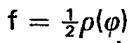

- Substituting the expression for p(cp) into the latter integral equation gives a relation between ω and ϕ, thus ω = ω(ϕ); hence, σ = p + ω is also determined as a function of ϕ. Subsequently, the equation:


- These coordinates are now dependent upon x and ϕ only, thus determining the shape of an inverted cosecant antenna.
- If the gain factor is not defined exclusively for the interval (ω1; ω2) (to obtain an inverted cosecant beam pattern), but also for the interval (ω0; ω1), for instance for a pencil beam pattern, a calculation similar to that above can be applied provided that the values ϕ1, ω1 and ρ0(ϕ1) in the required formulas are replaced with ϕ0, ω0 and ρ0(ϕ0) respectively, and that the appropriate gain formula for the respective angle interval is applied. Also further extensions of the antenna beam pattern outside the interval (ω1; ω2) are permitted.
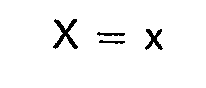
- It is also possible to use, instead of a doubly curved reflector and a point radiator, a singly curved reflector with a line feed (such as a slotted radiator) to obtain the inverted cosecant antenna pattern. The coordinates for such an antenna pattern are expressed by


- As already stated, an inverted cosecant antenna is to be used in combination with a sensitivity time control (STC) circuit.
- In principle, the STC circuit to be used should have a gain varying with the square of the range, as stated before. A feasible embodiment of such an STC circuit of the ASDE radar in accordance with the invention, is illustrated in Fig. 3.
- The STC circuit in this figure comprises an r.f.
amplifier 10, amixer 11. a preamplifier 12 and amain amplifier 13, all interconnected in the given sequence. The r.f. echo signal received by the antenna is supplied to the r.f.amplifier 10 to produce a usually weaker signal, which is transformed in themixer 11 into an i.f. signal by means of the output signal of alocal oscillator 14. The output signal ofmixer 11 is then applied to the preamplifier 12 and the main amplifies 13. - For the voltage control of the r.f.
amplifier 10, the preamplifier 12 and themain amplifier 13, the STC circuit further comprises a firstsawtooth generator 15, a second sawtooth generator and anAGC circuit 17, while for the signal suppression at the instant of the transmitter pulse the STC circuit is also provided with apulse suppression unit 18. The output voltage ofsuppression unit 18 and of thesawtooth generator 15 are supplied to the r.f.amplifier 10 via separate diodes D, and D2, and to the preamplifier 12 via separate diodes D3 and D4. For the voltage control of themain amplifier 13 the output voltages of thesawtooth generator 16 and those of theAGC circuit 17 are available. These output voltages are applied to themain amplifier 13 via separate diodes D5 and D6' - The slope of the output voltage of each of the sawtooth generators should be of such a value that the STC circuit exhibits predominantly the desired characteristic, i.e. a voltage characteristic varying with the square of the distance R (see Fig. 4A). The voltage characteristics of the
sawtooth generators main amplifier 13 is shown in Fig. 4D From a time to, directly preceding the instant of the synchronisation pulse S, to time t, when the transmitter produces a pulse. thepulse suppression unit 18 and thesawtooth generators suppression unit 18 is increased. Thesawtooth generators - From time t, when the square pulse disappears, the
sawtooth generator 15 does produce an output voltage following a fixed slope, so that the control voltage of the r.f.amplifier 10 and preamplifier 12 will vary accordingly. - From time t2 the control voltage of the
sawtooth generator 16 will be dominant at themain amplifier 13; consequently, from time t2 the total gain characteristic will show a different slope. - Since the
AGC circuit 17 drives themain amplifiers 13 in such a way that the gain characteristic (see Fig. 4A) in the entire receiver amplification range remains constant, this gain characteristic will have a maximum value at a time preceding to and following on a certain time t3. - The slope of the consecutive rectilinear fractions of the characteristic in Fig. 4A wil! be of such a value that the variation of the gain characteristic will be approximately quadratic.
- It may be desirable to adjust the slope values in order to attenuate meteorological echoes by a factor exp(-αR), where α is an attenuation coefficient (see Skolnik M.I.: Introduction to Radar Systems, 1962, Sec. 12.5).
- An obvious variant of the above STC circuit is obtained when, instead of
separate amplifiers 12 and 13, a single amplifier is used. In such a case, the voltages supplied via diodes D3, D4, D5 and D6 should be applied to such an amplifier via a common line.
Claims (4)

Applications Claiming Priority (2)
| Application Number | Priority Date | Filing Date | Title |
|---|---|---|---|
| NL7800163 | 1978-01-06 | ||
| NL7800163A NL7800163A (en) | 1978-01-06 | 1978-01-06 | ASDE RADAR DEVICE. |
Publications (2)
| Publication Number | Publication Date |
|---|---|
| EP0003485A1 EP0003485A1 (en) | 1979-08-22 |
| EP0003485B1 true EP0003485B1 (en) | 1981-10-28 |
Family
ID=19830099
Family Applications (1)
| Application Number | Title | Priority Date | Filing Date |
|---|---|---|---|
| EP78200346A Expired EP0003485B1 (en) | 1978-01-06 | 1978-12-05 | Airport surface detection equipment |
Country Status (7)
| Country | Link |
|---|---|
| US (1) | US4213126A (en) |
| EP (1) | EP0003485B1 (en) |
| JP (1) | JPS5932745B2 (en) |
| CA (1) | CA1106476A (en) |
| DE (1) | DE2861275D1 (en) |
| IT (1) | IT1113741B (en) |
| NL (1) | NL7800163A (en) |
Families Citing this family (13)
| Publication number | Priority date | Publication date | Assignee | Title |
|---|---|---|---|---|
| US4435707A (en) | 1981-03-09 | 1984-03-06 | Sperry Corporation | Weather radar with signal compensation for precipitation |
| FR2600167B1 (en) * | 1986-06-17 | 1988-12-09 | Thomson Csf | METHOD AND DEVICE FOR CORRECTING THE OBILITY OF THE DISTANCE MEASUREMENT OF A SHORT-RANGE RADAR |
| US4837574A (en) * | 1987-04-17 | 1989-06-06 | The Boeing Company | Near-field monostatic intrusion detection system |
| FR2669115B1 (en) * | 1990-11-09 | 1993-04-23 | Thomson Csf | MILLIMETER WAVE RADAR SYSTEM FOR GUIDANCE OF A MOBILE ROBOT ON THE GROUND. |
| US5448243A (en) * | 1991-12-30 | 1995-09-05 | Deutsche Forschungsanstalt Fur Luft- Und Raumfahrt E.V. | System for locating a plurality of objects and obstructions and for detecting and determining the rolling status of moving objects, such as aircraft, ground vehicles, and the like |
| US5300933A (en) * | 1993-02-24 | 1994-04-05 | Daniel H. Wagner Associates, Inc. | Stick figure radar tracking process |
| FR2706624B1 (en) * | 1993-06-14 | 1995-09-29 | Dassault Electronique | Ground surveillance radar device, especially for airports. |
| US5519618A (en) * | 1993-08-02 | 1996-05-21 | Massachusetts Institute Of Technology | Airport surface safety logic |
| US5623268A (en) * | 1994-10-06 | 1997-04-22 | British Technology Group Ltd. | Device for protecting SSR transponders against unintended triggering on an airport with very limited muting activity in vertical direction |
| US5659319A (en) * | 1995-12-21 | 1997-08-19 | Cardion, Inc. | Method and apparatus for operating a surface detection surveillance radar using frequency agile pulse transmissions |
| DE19619015B4 (en) * | 1996-05-10 | 2006-11-02 | Deutsches Zentrum für Luft- und Raumfahrt e.V. | Method and arrangement for traffic monitoring |
| US20050104766A1 (en) * | 2003-11-14 | 2005-05-19 | Brian Bandhauer | Radar detection zone pattern shaping |
| US7576683B2 (en) * | 2006-08-07 | 2009-08-18 | Honeywell International Inc. | Methods and systems for reducing interference caused by antenna leakage signals |
Family Cites Families (4)
| Publication number | Priority date | Publication date | Assignee | Title |
|---|---|---|---|---|
| US2653241A (en) * | 1945-07-09 | 1953-09-22 | Chu Lan Jen | Antenna |
| GB797830A (en) * | 1954-08-20 | 1958-07-09 | Philco Corp | Improvements in and relating to electrical systems for modifying electric signals |
| US2690508A (en) * | 1947-01-10 | 1954-09-28 | Bell Telephone Labor Inc | Directive antenna system |
| US3659290A (en) * | 1970-08-03 | 1972-04-25 | Sanders Associates Inc | Apparatus for providing sensitivity-time control for radar receivers |
-
1978
- 1978-01-06 NL NL7800163A patent/NL7800163A/en not_active Application Discontinuation
- 1978-12-05 EP EP78200346A patent/EP0003485B1/en not_active Expired
- 1978-12-05 DE DE7878200346T patent/DE2861275D1/en not_active Expired
- 1978-12-07 CA CA318,140A patent/CA1106476A/en not_active Expired
- 1978-12-13 US US05/968,941 patent/US4213126A/en not_active Expired - Lifetime
-
1979
- 1979-01-05 IT IT47548/79A patent/IT1113741B/en active
- 1979-01-06 JP JP54000553A patent/JPS5932745B2/en not_active Expired
Also Published As
| Publication number | Publication date |
|---|---|
| DE2861275D1 (en) | 1982-01-07 |
| CA1106476A (en) | 1981-08-04 |
| IT7947548A0 (en) | 1979-01-05 |
| NL7800163A (en) | 1979-07-10 |
| JPS5932745B2 (en) | 1984-08-10 |
| US4213126A (en) | 1980-07-15 |
| JPS5498193A (en) | 1979-08-02 |
| EP0003485A1 (en) | 1979-08-22 |
| IT1113741B (en) | 1986-01-20 |
Similar Documents
| Publication | Publication Date | Title |
|---|---|---|
| Lewinski | Nonstationary probabilistic target and clutter scattering models | |
| EP0003485A1 (en) | Airport surface detection equipment | |
| US3604805A (en) | Optical detecting and ranging system for automotive vehicles | |
| IL110311A (en) | Three dimensional imaging millimeter wave seeker | |
| DE2026020A1 (en) | Proximity warning system for plug-in tools | |
| WO1999046831A1 (en) | Wire detection system and method | |
| Marty et al. | From passive to active radar reflectors and beyond | |
| Bracalente et al. | Airborne Doppler radar detection of low-altitude wind shear | |
| US3528070A (en) | Multifunction crossed beam radar system | |
| Shibao et al. | Road debris detection using 79ghz radar | |
| US3259898A (en) | Doppler radar system | |
| Carrara et al. | Motion compensation algorithm for widebeam stripmap SAR | |
| US3357014A (en) | Standard target radar | |
| DE4206327A1 (en) | Two-frequency transmitter with audio modulation phasing - radiates clearance signal into broader angle than course signal for suppression of difference-of-depth-of-modulation interference | |
| GB2177870A (en) | High resolution radar system | |
| Fontana et al. | Ultrawideband synthetic vision sensor for airborne wire detection | |
| US2643374A (en) | System of aerial navigation | |
| US3594791A (en) | Radiation-operated distance meter | |
| US20130222171A1 (en) | Radio-frequency (rf) precision nulling device | |
| US3747094A (en) | Correlator | |
| JPH0535599U (en) | Unmanned aerial vehicle landing guidance system | |
| Duboc | Corner reflectors | |
| Palmer et al. | JOINT ARMY-NAVY AIRCRAFT INSTRUMENTATION RESEARCH (JANAIR) ROTOR BLADE RADAR ANTENNA-PHASE 2 | |
| Pannell et al. | RADAR SCATTERING FROM A CONDUCTING CONESPHERE | |
| Crane | Predictions of Transhorizon Field Strengths Using Modeling Techniques |
Legal Events
| Date | Code | Title | Description |
|---|---|---|---|
| PUAI | Public reference made under article 153(3) epc to a published international application that has entered the european phase |
Free format text: ORIGINAL CODE: 0009012 |
|
| AK | Designated contracting states |
Designated state(s): BE CH DE FR GB NL SE |
|
| 17P | Request for examination filed | ||
| GRAA | (expected) grant |
Free format text: ORIGINAL CODE: 0009210 |
|
| AK | Designated contracting states |
Designated state(s): BE CH DE FR GB NL SE |
|
| REF | Corresponds to: |
Ref document number: 2861275 Country of ref document: DE Date of ref document: 19820107 |
|
| NLT1 | Nl: modifications of names registered in virtue of documents presented to the patent office pursuant to art. 16 a, paragraph 1 |
Owner name: HASRODE B.V. TE EINDHOVEN. |
|
| NLS | Nl: assignments of ep-patents |
Owner name: HOLLANDSE SIGNAALAPPARATEN B.V. TE HENGELO (O.). |
|
| REG | Reference to a national code |
Ref country code: GB Ref legal event code: 732 |
|
| REG | Reference to a national code |
Ref country code: FR Ref legal event code: TP Ref country code: FR Ref legal event code: CD Ref country code: FR Ref legal event code: CA |
|
| REG | Reference to a national code |
Ref country code: CH Ref legal event code: PUE Owner name: HOLLANDSE SIGNAALAPPARATEN B.V. Ref country code: CH Ref legal event code: PFA Free format text: HASRODE B.V. |
|
| BECA | Be: change of holder's address |
Free format text: 920923 *HOLLANDSE SIGNAALAPPARATEN B.V.:ZUIDELIJKE HAVENWEG 40, 7554 RR HENGELO |
|
| BECH | Be: change of holder |
Free format text: 920923 *HOLLANDSE SIGNAALAPPARATEN B.V. |
|
| PGFP | Annual fee paid to national office [announced via postgrant information from national office to epo] |
Ref country code: SE Payment date: 19941114 Year of fee payment: 17 |
|
| PGFP | Annual fee paid to national office [announced via postgrant information from national office to epo] |
Ref country code: FR Payment date: 19941115 Year of fee payment: 17 |
|
| PGFP | Annual fee paid to national office [announced via postgrant information from national office to epo] |
Ref country code: DE Payment date: 19941116 Year of fee payment: 17 |
|
| PGFP | Annual fee paid to national office [announced via postgrant information from national office to epo] |
Ref country code: GB Payment date: 19941125 Year of fee payment: 17 |
|
| PGFP | Annual fee paid to national office [announced via postgrant information from national office to epo] |
Ref country code: CH Payment date: 19941202 Year of fee payment: 17 |
|
| PGFP | Annual fee paid to national office [announced via postgrant information from national office to epo] |
Ref country code: BE Payment date: 19941214 Year of fee payment: 17 |
|
| PGFP | Annual fee paid to national office [announced via postgrant information from national office to epo] |
Ref country code: NL Payment date: 19941231 Year of fee payment: 17 |
|
| EAL | Se: european patent in force in sweden |
Ref document number: 78200346.1 |
|
| PG25 | Lapsed in a contracting state [announced via postgrant information from national office to epo] |
Ref country code: GB Effective date: 19951205 |
|
| PG25 | Lapsed in a contracting state [announced via postgrant information from national office to epo] |
Ref country code: SE Effective date: 19951206 |
|
| PG25 | Lapsed in a contracting state [announced via postgrant information from national office to epo] |
Ref country code: CH Effective date: 19951231 Ref country code: BE Effective date: 19951231 |
|
| BERE | Be: lapsed |
Owner name: HOLLANDSE SIGNAALAPPARATEN B.V. Effective date: 19951231 |
|
| PG25 | Lapsed in a contracting state [announced via postgrant information from national office to epo] |
Ref country code: NL Effective date: 19960701 |
|
| GBPC | Gb: european patent ceased through non-payment of renewal fee |
Effective date: 19951205 |
|
| REG | Reference to a national code |
Ref country code: CH Ref legal event code: PL |
|
| PG25 | Lapsed in a contracting state [announced via postgrant information from national office to epo] |
Ref country code: FR Effective date: 19960830 |
|
| NLV4 | Nl: lapsed or anulled due to non-payment of the annual fee |
Effective date: 19960701 |
|
| PG25 | Lapsed in a contracting state [announced via postgrant information from national office to epo] |
Ref country code: DE Effective date: 19960903 |
|
| REG | Reference to a national code |
Ref country code: FR Ref legal event code: ST |
|
| PLBE | No opposition filed within time limit |
Free format text: ORIGINAL CODE: 0009261 |
|
| STAA | Information on the status of an ep patent application or granted ep patent |
Free format text: STATUS: NO OPPOSITION FILED WITHIN TIME LIMIT |