EP0003418B1 - Tire loader - Google Patents
Tire loader Download PDFInfo
- Publication number
- EP0003418B1 EP0003418B1 EP19790300103 EP79300103A EP0003418B1 EP 0003418 B1 EP0003418 B1 EP 0003418B1 EP 19790300103 EP19790300103 EP 19790300103 EP 79300103 A EP79300103 A EP 79300103A EP 0003418 B1 EP0003418 B1 EP 0003418B1
- Authority
- EP
- European Patent Office
- Prior art keywords
- loader
- plate
- shoe
- shoes
- loader according
- Prior art date
- Legal status (The legal status is an assumption and is not a legal conclusion. Google has not performed a legal analysis and makes no representation as to the accuracy of the status listed.)
- Expired
Links
Images
Classifications
-
- B—PERFORMING OPERATIONS; TRANSPORTING
- B29—WORKING OF PLASTICS; WORKING OF SUBSTANCES IN A PLASTIC STATE IN GENERAL
- B29D—PRODUCING PARTICULAR ARTICLES FROM PLASTICS OR FROM SUBSTANCES IN A PLASTIC STATE
- B29D30/00—Producing pneumatic or solid tyres or parts thereof
- B29D30/0016—Handling tyres or parts thereof, e.g. supplying, storing, conveying
Definitions
- This invention relates generally as indicated to a tire loader and more particularly to a loader mechanism for use with tire machinery such as tire curing presses.
- Tire loaders have been widely employed in connection with automated tire machinery such as tire curing presses. Most such tire loaders pick up the tire by the upper bead and the shoes of such loader exert a slight pressure on the interior of the upper bead which can cause bead distortion. Moreover, in some tire loaders such pressure is required for centering purposes, yet must be sufficiently light to permit the tire to slip down the loader shoes so that the upper bead of the tire is seated on a lip on the lower edge of the shoes and is positioned properly horizontally. If the tire does not seat properly on the lip it may not be in proper position for loading. Moreover, with the advent of radial tires, it becomes very important that the tire be very accurately located at the center of the mold cavity.
- loaders are quite complex and require time consuming shimming operations properly to center the loader shoes over the mold cavity. Such shimming operations increase tire press down time resulting in lower productivity. Moreover, many such loaders are quite complex and take up a substantial amount of vertical space which can create clearance problems as well as service problems. Further, with many complex parts subject to wear, loaders may require frequent part replacements or further shimming operations to compensate for such wear.
- Some prior art loaders employ a horizontally disposed oscillating actuating plate which may be in the form of a scroll cam plate. Examples of such mechanisms may be seen in Soderquist U.S. Patent 3,380,115 and Soderquist U.S. Patent 3,564,649. Many other prior art loaders employ vertically oriented actuators as seen in Soderquist U.S. Patent 3,167,810. Other loaders such as shown in Schatz et al U.S. Patent 3,845,979 employ a piston-cylinder actuator for each loader shoe.
- a carrier for radial green tires, not a tire loader, has been proposed in U.S. Patent 3 393 807, including a tire-engaging unit which is expansible and retractable by means of inextensible manually movable crank arms.
- a tire loader having a horizontal plate mounted for rotation on a vertical axis, loader shoes mounted for radial movement to and from said axis, and respective link means interconnecting the plate and each shoe, with each link means extending at the same angle with respect to the radial line of motion at its associated shoe whereby rotation of the plate in one direction will reduce said angle thus moving the shoes radially outwardly and rotation of the plate in the opposite direction will increase said angle thus moving the shoes radially inwardly, characterised in that the link means comprises adjustable length connecting rods hingedly connected to the horizontal plate and the respective shoes.
- the tire loader has reduced weight, requiring less energy consumption, and ease of serviceability, as well as adjustability, including both centering and stroke limit adjustability as well as vertical height adjustment.
- the loader is less subject to wear and has greater repeatable reliability.
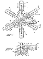
- the embodiment of the invention illustrated comprises a vertically extending pin 10 to which is secured horizontally extending support plate 11, the profile configuration of which is seen in Figure 1.
- the plate includes two angularly related arms 12 and 13, the latter being somewhat longer.
- the underside of the plate includes a vertically projecting hub 14 which is keyed to the pin 10 as indicated at 15.
- the plate is held in place on the pin by a snap ring or retainer 16.
- the lower end of the pin 10 has secured thereto a flange forming ring 18, the lower surface of which is beneath the lower end 19 of the pin.
- a fastener 20 Secured to the underside of the ring flange 18 by the fasteners 20 are six equally circumferentially spaced radially extending horizontal slide bars 21. The slide bars are pointed at their inner ends as seen in Fig. 1 to fit together in the manner indicated.
- the pin is provided with a vertically elongated sleeve journaled top and bottom on the pin 10 as indicated at 24 and 25, respectively.
- a circular plate 27 Secured to the sleeve near the lower end thereof is a circular plate 27.
- the sleeve is provided with two diametrically opposed projecting arms 28 and 29 which are the same length as the radius of the plate 27.
- the sleeve is oscillated by means of piston cylinder assembly 31, the rod 32 thereof being provided with a clevis 33 pivotally connected at 34 to the projecting arm 28.
- the blind end of the piston cylinder assembly is pivotally supported on stub bracket 35 secured at 36 to the end of arm 13 of the support plate 11.
- the stroke of the piston cylinder assembly is limited at both ends by the stroke limiting assembly generally shown at 40.
- Such assembly comprises a threaded stroke limiter rod 41 pivotally connected at 42 to the arm 29.
- Such rod 41 may extend through a spherical guide bushing or aperture 43 in stop bracket 44 secured to the underside of the plate 11.
- Adjustable stroke limiting lock nuts are provided on the threaded limiter rod as indicated at 46 and 47 on each side of the stop block. In the illustrated position, the stop 46 is in engagement with the stop block 44 and the extended condition of the piston cylinder assembly 31 is thus limited. Conversely, when the stop 47 is in engagement with the opposite face of the stop 44, the piston cylinder assembly 31 is limited in its retraction.
- Each loader shoe 50 is formed from relatively thin gauge metal, almost sheet metal.
- Each shoe includes a vertically extending spine plate which is slightly curved as seen at 51. Such plate has an aperture 52 therein near its top to accommodate a slide bar 21. Adjacent its bottom it is bent outwardly slightly as indicated at 53 to form a lip 54 adapted to engage the upper bead 55 of the tire 56.
- the tire 56 is illustrated as a non-belted or bias ply tire, the loader can in equal fashion accommodate belted or radial play tires as well as cured tires.
- the curvature of the spine plate 53 is determined by the range of tire sizes which may be accommodated by the loader.
- the edges of the spine plate are folded rearwardly to form parallel plates or ears 59 and 60 each of which have the arcuate lower edges seen at 61.
- Each bridge plate may have two or more radially spaced tapped apertures as indicated at 65.
- each of the self-aligning slide blocks includes a shallow groove confining the slide bar 21.
- the slide blocks are an elastomeric material such as a phenolic resin or nylon having lubricating properties.
- Each loader shoe is connected to the circular plate 27 by a connecting rod 82.
- Each connecting rod includes at each end eyes 83 and 84 threadedly connected to the shank 85 which are in turn hingedly connected at 86 and 87 to the top of the bridge plate 63 and the top or bottom of the plate 27, respectively.
- the effective length of each rod 82 may of course be adjusted by rotating the shank 85 with respect to the eyes 83 and 84, when the respective lock nuts shown at 88 and 89 are loosened.
- the range of movement may be selected by selecting one of the apertures 65 for the hinge connection 86.
- each link extends at a common angle with respect to a radius so that rotation of the sleeve 23 and thus the plate 27 in one direction will reduce the angle moving the shoes radially outwardly and rotation of the sleeve and accordingly the plate 27 in the opposite direction will increase the angle moving the shoes radially uniformly inwardly.
- the radial outer ends of the slide bars 21 are feathered slightly as indicated at 95 readily to permit the loader shoes to be removed and repositioned thereon.
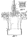
- the pin 10 may include an upper threaded removable part 96 which is threaded into a tapped aperture in the pin 10 as seen at 97 and held in place by locking pin 98.
- the threaded extension 96 of the pin 10 may be employed vertically adjust- ably to support the loader on horizontal elevator frame member 99. Vertical adjustment and locking is obtained by top and bottom locks nuts 100 and 101 and respective washers 102 and 103.
- the top nut may be shouldered to fit in a countersunk opening in the top of frame 99 for precision centering. Thus the entire vertical height of the loader with respect to the elevator frame 99 may readily be vertically adjusted.
- the elevator frame may be of the type wherein a horizontal frame extends between two vertical rails mounted on the press head for vertical and horizontal movement therewith.
- the frame 99 may be of the swinging jib arm type and in any event will normally move vertically and horizontally to pick up and reposition the tire as required.
- a limit switch may be mounted on the plate 11 which may include a feeler arm which may project below the plate to sense the position of the loader with respect to a tire to be picked up.
- Such limit switch and sensing arm may be mounted on the extension 12 of plate 11 as seen in Figure 1.
- the sensor may also be employed to sense the position of the loader with respect to an object adjacent the deposit location of the tire such as a center mechanism of a tire press.
Description
- This invention relates generally as indicated to a tire loader and more particularly to a loader mechanism for use with tire machinery such as tire curing presses.
- Tire loaders have been widely employed in connection with automated tire machinery such as tire curing presses. Most such tire loaders pick up the tire by the upper bead and the shoes of such loader exert a slight pressure on the interior of the upper bead which can cause bead distortion. Moreover, in some tire loaders such pressure is required for centering purposes, yet must be sufficiently light to permit the tire to slip down the loader shoes so that the upper bead of the tire is seated on a lip on the lower edge of the shoes and is positioned properly horizontally. If the tire does not seat properly on the lip it may not be in proper position for loading. Moreover, with the advent of radial tires, it becomes very important that the tire be very accurately located at the center of the mold cavity. Many currently employed loaders are quite complex and require time consuming shimming operations properly to center the loader shoes over the mold cavity. Such shimming operations increase tire press down time resulting in lower productivity. Moreover, many such loaders are quite complex and take up a substantial amount of vertical space which can create clearance problems as well as service problems. Further, with many complex parts subject to wear, loaders may require frequent part replacements or further shimming operations to compensate for such wear.
- Some prior art loaders employ a horizontally disposed oscillating actuating plate which may be in the form of a scroll cam plate. Examples of such mechanisms may be seen in Soderquist U.S. Patent 3,380,115 and Soderquist U.S. Patent 3,564,649. Many other prior art loaders employ vertically oriented actuators as seen in Soderquist U.S. Patent 3,167,810. Other loaders such as shown in Schatz et al U.S. Patent 3,845,979 employ a piston-cylinder actuator for each loader shoe.
- In connection with tire press loaders which employ a horizontally disposed cam or scroll plate, wherein a follower rides in a cam slot, there is an inherent clearance between the slot and follower which reduces the precision of centering obtainable in addition to creating other obvious problems such as initial cost and wear.
- A carrier for radial green tires, not a tire loader, has been proposed in U.S.
Patent 3 393 807, including a tire-engaging unit which is expansible and retractable by means of inextensible manually movable crank arms. - There is a need to provide a tire loader which will not distort the bead of a tire when the loader is engaged therewith, which permits a green tire to be accurately located at the center of a mold cavity of a tire press, and which can be centered or adjusted in a minimum amount of time reducing loader alignment down time and resulting in higher productivity for the press.
- According to the present invention there is provided a tire loader having a horizontal plate mounted for rotation on a vertical axis, loader shoes mounted for radial movement to and from said axis, and respective link means interconnecting the plate and each shoe, with each link means extending at the same angle with respect to the radial line of motion at its associated shoe whereby rotation of the plate in one direction will reduce said angle thus moving the shoes radially outwardly and rotation of the plate in the opposite direction will increase said angle thus moving the shoes radially inwardly, characterised in that the link means comprises adjustable length connecting rods hingedly connected to the horizontal plate and the respective shoes.
- The tire loader has reduced weight, requiring less energy consumption, and ease of serviceability, as well as adjustability, including both centering and stroke limit adjustability as well as vertical height adjustment. In addition, the loader is less subject to wear and has greater repeatable reliability.
- For a better understanding of the present invention, and to show how it may be carried into effect, reference will now be made, by way of example, to the accompanying drawings, in which:-
- Figure 1 is a top plan view of one form of loader in accordance with the present invention;
- Figure 2 is a side elevation partially broken away and in section taken substantially from the line 2-2 of Figure 1;
- Figure 3 is a vertical section, again partially broken away, taken from the line 3-3 of Figure 1 and illustrating the support for the loader and the vertical adjustment between the support and the loader; and
- Figure 4 is an enlarged vertical section taken substantially on the line 4-4 of Figure 3.
- Referring first to Figs. 1-3 it will be seen that the embodiment of the invention illustrated comprises a vertically extending
pin 10 to which is secured horizontally extending support plate 11, the profile configuration of which is seen in Figure 1. The plate includes two angularlyrelated arms hub 14 which is keyed to thepin 10 as indicated at 15. The plate is held in place on the pin by a snap ring orretainer 16. - The lower end of the
pin 10 has secured thereto aflange forming ring 18, the lower surface of which is beneath thelower end 19 of the pin. Secured to the underside of thering flange 18 by thefasteners 20 are six equally circumferentially spaced radially extendinghorizontal slide bars 21. The slide bars are pointed at their inner ends as seen in Fig. 1 to fit together in the manner indicated. - Between the
hub 14 of the support plate 11 and thebottom ring flange 18 the pin is provided with a vertically elongated sleeve journaled top and bottom on thepin 10 as indicated at 24 and 25, respectively. Secured to the sleeve near the lower end thereof is acircular plate 27. Near the upper end, the sleeve is provided with two diametrically opposed projectingarms plate 27. - The sleeve is oscillated by means of
piston cylinder assembly 31, therod 32 thereof being provided with aclevis 33 pivotally connected at 34 to the projectingarm 28. The blind end of the piston cylinder assembly is pivotally supported onstub bracket 35 secured at 36 to the end ofarm 13 of the support plate 11. - The stroke of the piston cylinder assembly is limited at both ends by the stroke limiting assembly generally shown at 40. Such assembly comprises a threaded
stroke limiter rod 41 pivotally connected at 42 to thearm 29.Such rod 41 may extend through a spherical guide bushing or aperture 43 instop bracket 44 secured to the underside of the plate 11. Adjustable stroke limiting lock nuts are provided on the threaded limiter rod as indicated at 46 and 47 on each side of the stop block. In the illustrated position, thestop 46 is in engagement with thestop block 44 and the extended condition of thepiston cylinder assembly 31 is thus limited. Conversely, when thestop 47 is in engagement with the opposite face of thestop 44, thepiston cylinder assembly 31 is limited in its retraction. - For each
slide bar 21 there is provided aloader shoe 50, each of which is identical in form and accordingly only one will be described in detail. Eachloader shoe 50 is formed from relatively thin gauge metal, almost sheet metal. Each shoe includes a vertically extending spine plate which is slightly curved as seen at 51. Such plate has anaperture 52 therein near its top to accommodate aslide bar 21. Adjacent its bottom it is bent outwardly slightly as indicated at 53 to form alip 54 adapted to engage theupper bead 55 of thetire 56. It will be appreciated that while thetire 56 is illustrated as a non-belted or bias ply tire, the loader can in equal fashion accommodate belted or radial play tires as well as cured tires. The curvature of thespine plate 53 is determined by the range of tire sizes which may be accommodated by the loader. - Slightly less than half the distance from the bottom, the edges of the spine plate are folded rearwardly to form parallel plates or
ears - Such parallel plates are interconnected by a
bridge plate 63 which extends slightly above thetop edges 64. As seen, the bridge block is sufficiently shallow so as to clear theslide bar 21 which passes therebeneath. Each bridge plate may have two or more radially spaced tapped apertures as indicated at 65. - In addition, the
parallel plates bolt fasteners slide bar 21. Preferably the slide blocks are an elastomeric material such as a phenolic resin or nylon having lubricating properties. It can thus be seen that thefasteners 66 together with the spacers not only maintain theplates - Each loader shoe is connected to the
circular plate 27 by a connectingrod 82. Each connecting rod includes at eachend eyes shank 85 which are in turn hingedly connected at 86 and 87 to the top of thebridge plate 63 and the top or bottom of theplate 27, respectively. The effective length of eachrod 82 may of course be adjusted by rotating theshank 85 with respect to theeyes apertures 65 for thehinge connection 86. - It can now be seen that rotation of the
plate 27 will move theloader shoe 50 uniformly radially along theslide bars 21. In Figures 1 the shoes are illustrated at their maximum diameter. Upon retraction of thepiston cylinder assembly 31 theplate 27 will rotate in a counterclockwise direction as seen in Figure 1 moving the connecting links uniformly at a common angle with respect to a radius from thepin 10 to achieve the phantom line position 90 seen in Figure 1 when the shoes achieve theposition 91 seen in Figure 3. In this manner each link extends at a common angle with respect to a radius so that rotation of thesleeve 23 and thus theplate 27 in one direction will reduce the angle moving the shoes radially outwardly and rotation of the sleeve and accordingly theplate 27 in the opposite direction will increase the angle moving the shoes radially uniformly inwardly. It is noted that the radial outer ends of the slide bars 21 are feathered slightly as indicated at 95 readily to permit the loader shoes to be removed and repositioned thereon. - As seen more clearly in Figure 3, the
pin 10 may include an upper threadedremovable part 96 which is threaded into a tapped aperture in thepin 10 as seen at 97 and held in place by lockingpin 98. The threadedextension 96 of thepin 10 may be employed vertically adjust- ably to support the loader on horizontalelevator frame member 99. Vertical adjustment and locking is obtained by top andbottom locks nuts respective washers frame 99 for precision centering. Thus the entire vertical height of the loader with respect to theelevator frame 99 may readily be vertically adjusted. The elevator frame may be of the type wherein a horizontal frame extends between two vertical rails mounted on the press head for vertical and horizontal movement therewith. Conversely, theframe 99 may be of the swinging jib arm type and in any event will normally move vertically and horizontally to pick up and reposition the tire as required. - A limit switch, not shown, may be mounted on the plate 11 which may include a feeler arm which may project below the plate to sense the position of the loader with respect to a tire to be picked up. Such limit switch and sensing arm may be mounted on the
extension 12 of plate 11 as seen in Figure 1. The sensor may also be employed to sense the position of the loader with respect to an object adjacent the deposit location of the tire such as a center mechanism of a tire press. - While there is illustrated the employment of six shoes, it will be appreciated that more or less, but more than two, may equally well be employed.
- In any event there is provided an inexpensive, easy to operate and maintain loader for tires which can readily be centered and which will minimize bead distortion.
- Other modes of applying the principle of the invention may be employed, change being made as regards the details described, provided the features stated in any of the following claims or the equivalent of such be employed.
Claims (10)
Applications Claiming Priority (2)
| Application Number | Priority Date | Filing Date | Title |
|---|---|---|---|
| US87242178A | 1978-01-26 | 1978-01-26 | |
| US872421 | 1978-01-26 |
Publications (2)
| Publication Number | Publication Date |
|---|---|
| EP0003418A1 EP0003418A1 (en) | 1979-08-08 |
| EP0003418B1 true EP0003418B1 (en) | 1982-04-14 |
Family
ID=25359541
Family Applications (1)
| Application Number | Title | Priority Date | Filing Date |
|---|---|---|---|
| EP19790300103 Expired EP0003418B1 (en) | 1978-01-26 | 1979-01-19 | Tire loader |
Country Status (7)
| Country | Link |
|---|---|
| EP (1) | EP0003418B1 (en) |
| JP (1) | JPS54105184A (en) |
| AR (1) | AR217134A1 (en) |
| BR (1) | BR7900470A (en) |
| CA (1) | CA1130066A (en) |
| DE (1) | DE2962488D1 (en) |
| TR (1) | TR20573A (en) |
Families Citing this family (5)
| Publication number | Priority date | Publication date | Assignee | Title |
|---|---|---|---|---|
| JPS58179633A (en) * | 1982-04-03 | 1983-10-20 | Kobe Steel Ltd | Gripping device of unvulcanized tire |
| EP0092598B1 (en) * | 1982-04-28 | 1985-10-09 | Fried. Krupp Gesellschaft mit beschränkter Haftung | Tyre loader |
| US5395150A (en) * | 1993-10-29 | 1995-03-07 | National Feedscrew & Machining Ind., Inc. | Loader basket assembly for tire press |
| US5716089A (en) * | 1996-07-29 | 1998-02-10 | Mcneil & Nrm, Inc. | Tire loader basket |
| CN102416678B (en) * | 2011-11-12 | 2013-09-25 | 宁波朗迪叶轮机械有限公司 | Forming machine for making shaft sleeve assembly on tubular fan blade |
Family Cites Families (4)
| Publication number | Priority date | Publication date | Assignee | Title |
|---|---|---|---|---|
| US3393807A (en) * | 1965-10-20 | 1968-07-23 | Tecto Corp | Carrier for radial green tires |
| US3380115A (en) * | 1966-01-28 | 1968-04-30 | Mcneil Corp | Universal tire press loader |
| JPS513754A (en) * | 1974-06-28 | 1976-01-13 | Hitachi Ltd | Akuteibufuirutano hogokairo |
| JPS51126275A (en) * | 1975-04-25 | 1976-11-04 | Kobe Steel Ltd | Suspending * conveying and equipping method for green tire |
-
1978
- 1978-12-22 JP JP15771978A patent/JPS54105184A/en active Granted
-
1979
- 1979-01-19 EP EP19790300103 patent/EP0003418B1/en not_active Expired
- 1979-01-19 DE DE7979300103T patent/DE2962488D1/en not_active Expired
- 1979-01-25 TR TR2057379A patent/TR20573A/en unknown
- 1979-01-25 CA CA320,307A patent/CA1130066A/en not_active Expired
- 1979-01-25 BR BR7900470A patent/BR7900470A/en unknown
- 1979-01-26 AR AR27531979A patent/AR217134A1/en active
Also Published As
| Publication number | Publication date |
|---|---|
| EP0003418A1 (en) | 1979-08-08 |
| DE2962488D1 (en) | 1982-05-27 |
| CA1130066A (en) | 1982-08-24 |
| JPS54105184A (en) | 1979-08-17 |
| JPS566855B2 (en) | 1981-02-14 |
| BR7900470A (en) | 1979-08-21 |
| AR217134A1 (en) | 1980-02-29 |
| TR20573A (en) | 1982-01-21 |
Similar Documents
| Publication | Publication Date | Title |
|---|---|---|
| US4279438A (en) | Tire loader | |
| US5441587A (en) | Transfer ring having selective adjustability of shoe movement | |
| CN1110405C (en) | Center split segmented mold for curing pneumatic tires | |
| US5635016A (en) | Transfer ring or drum apparatus with adjustable circumference | |
| US4105486A (en) | Tire component transfer | |
| EP2072232A1 (en) | Tire loader basket | |
| EP0003418B1 (en) | Tire loader | |
| JPH02280927A (en) | Device for fixing long parts such as punch, die or similar tools to mounting plate of bending press | |
| US20090295179A1 (en) | Tire lifting mechanism | |
| US3779677A (en) | Segmented tire mold | |
| US5395150A (en) | Loader basket assembly for tire press | |
| US5800843A (en) | Apparatus for injection molding plastic material | |
| US3267515A (en) | Tire curing press loader | |
| US4129406A (en) | Mold for the vulcanization or retreading of vehicle tires | |
| CA1106561A (en) | Tire curing press | |
| US4128450A (en) | Tire component building drum | |
| US4449903A (en) | Apparatus for loading and unloading tires for a tire vulcanizing machine | |
| US4131402A (en) | Device for the mutual centering of relatively movable mechanic elements, particularly used on tire curing presses | |
| EP0098524A2 (en) | Tire loader | |
| JPS634910A (en) | Tire vulcanizing mold | |
| US4990212A (en) | Device for applying an elastomeric filler on the bead core of a pneumatic tire | |
| US4144007A (en) | Tire stripping mechanism for dual cavity tire press | |
| US5716089A (en) | Tire loader basket | |
| JP2966178B2 (en) | Rim gap setting device for tire uniformity machine | |
| US4547012A (en) | Tire loader |
Legal Events
| Date | Code | Title | Description |
|---|---|---|---|
| PUAI | Public reference made under article 153(3) epc to a published international application that has entered the european phase |
Free format text: ORIGINAL CODE: 0009012 |
|
| AK | Designated contracting states |
Designated state(s): DE FR GB IT NL |
|
| 17P | Request for examination filed | ||
| ITF | It: translation for a ep patent filed |
Owner name: ST. ASSOC. MARIETTI & PIPPARELLI |
|
| GRAA | (expected) grant |
Free format text: ORIGINAL CODE: 0009210 |
|
| AK | Designated contracting states |
Designated state(s): DE FR GB IT NL |
|
| REF | Corresponds to: |
Ref document number: 2962488 Country of ref document: DE Date of ref document: 19820527 |
|
| PGFP | Annual fee paid to national office [announced via postgrant information from national office to epo] |
Ref country code: NL Payment date: 19830131 Year of fee payment: 5 |
|
| PG25 | Lapsed in a contracting state [announced via postgrant information from national office to epo] |
Ref country code: NL Effective date: 19840801 |
|
| NLV4 | Nl: lapsed or anulled due to non-payment of the annual fee | ||
| PGFP | Annual fee paid to national office [announced via postgrant information from national office to epo] |
Ref country code: FR Payment date: 19841210 Year of fee payment: 7 |
|
| PGFP | Annual fee paid to national office [announced via postgrant information from national office to epo] |
Ref country code: DE Payment date: 19841217 Year of fee payment: 7 |
|
| PG25 | Lapsed in a contracting state [announced via postgrant information from national office to epo] |
Ref country code: GB Effective date: 19890119 |
|
| GBPC | Gb: european patent ceased through non-payment of renewal fee | ||
| PG25 | Lapsed in a contracting state [announced via postgrant information from national office to epo] |
Ref country code: FR Free format text: LAPSE BECAUSE OF NON-PAYMENT OF DUE FEES Effective date: 19890929 |
|
| PG25 | Lapsed in a contracting state [announced via postgrant information from national office to epo] |
Ref country code: DE Effective date: 19891003 |
|
| REG | Reference to a national code |
Ref country code: FR Ref legal event code: ST |
|
| PLBE | No opposition filed within time limit |
Free format text: ORIGINAL CODE: 0009261 |
|
| STAA | Information on the status of an ep patent application or granted ep patent |
Free format text: STATUS: NO OPPOSITION FILED WITHIN TIME LIMIT |