EP0002730B1 - Head rest, in particular for vehicle seats - Google Patents
Head rest, in particular for vehicle seats Download PDFInfo
- Publication number
- EP0002730B1 EP0002730B1 EP78101668A EP78101668A EP0002730B1 EP 0002730 B1 EP0002730 B1 EP 0002730B1 EP 78101668 A EP78101668 A EP 78101668A EP 78101668 A EP78101668 A EP 78101668A EP 0002730 B1 EP0002730 B1 EP 0002730B1
- Authority
- EP
- European Patent Office
- Prior art keywords
- guide sleeve
- head rest
- rod
- pivot pin
- catches
- Prior art date
- Legal status (The legal status is an assumption and is not a legal conclusion. Google has not performed a legal analysis and makes no representation as to the accuracy of the status listed.)
- Expired
Links
Images

Classifications
-
- B—PERFORMING OPERATIONS; TRANSPORTING
- B60—VEHICLES IN GENERAL
- B60N—SEATS SPECIALLY ADAPTED FOR VEHICLES; VEHICLE PASSENGER ACCOMMODATION NOT OTHERWISE PROVIDED FOR
- B60N2/00—Seats specially adapted for vehicles; Arrangement or mounting of seats in vehicles
- B60N2/80—Head-rests
- B60N2/806—Head-rests movable or adjustable
- B60N2/838—Tiltable
Definitions
- the invention relates to a headrest, in particular for motor vehicle seats, which is anchored with two rods in brackets in the backrest of the seat, each rod being pivotable about a pivot pin parallel to the upper backrest edge and in different angular positions with respect to the backrest being spring-lockable and the pivot pin to disengage the headrest slides in elongated holes that extend substantially in the longitudinal direction of the rod.
- a headrest of this type is known (DE-A-23 18 381), in which a pivot pin and a toothing are arranged at each rod end, of which the pivot pin cooperates with elongated holes and the toothing with tooth pegs which are arranged in the holder, which are located inside the backrest, where the other parts of the mechanism for adjusting the angle of the headrest are housed.
- the headrest can therefore only be used together with a very specific backrest, the adjustment mechanism of which is adapted to it. It is also necessary to firmly install the adjustment mechanism in the backrest of the seat, since the ends of the headrest brackets with their projecting pivot pins cannot be subsequently inserted into the adjustment mechanism.
- the object of the invention is to provide an adjustable in its angular position to the backrest headrest, which is very simple and made from a few simple parts and can be installed together with its adjustment mechanism in tubular brackets of any seat back that the adjustment mechanism inside the backrest located.
- This configuration has the advantage that the headrest adjustment mechanism, although attached to the headrest itself, is moved to the inside of the backrest and can neither interfere nor cause injury.
- the adjustment mechanism has a very. takes up little space and disappears in the holder provided on the backrest, which encloses it in a protective manner.
- the headrest itself can then consist of a simple, padded bracket with padded cross struts, which gives the view to the person sitting behind the seat provided with the headrest.
- a locking pin is arranged in each free rod end and at a distance from the pivot pin, which engages in mutually opposite recesses in the walls of the guide sleeve that form a plurality of interconnected catches.
- Such an embodiment is particularly simple, since only two holes have to be drilled in each rod end and the pins which can engage in punched-out notches or elongated holes in the sleeve have to be inserted through them.
- the notches in the guide sleeve are preferably formed by V-shaped grooves, the legs of which are arranged next to the front of the headrest and run parallel to the longitudinal axis of the guide tube. These V-shaped grooves allow the headrest to pivot in two positions, which is usually sufficient.
- the arrangement of the grooves according to the invention ensures that the headrest cannot strike backwards in any position if the head is thrown against it in the event of an impact.
- the pivot pin can be arranged at a short distance from the rod end and can serve as an abutment for the detent spring, the other end of which is supported against a protrusion protruding into the interior of the guide sleeve.
- Such an embodiment is particularly simple since it is sufficient to push a compression spring over the rod end or into the rod in the lower region of the sleeve if the latter is tubular or has an axial bore in its lower end.
- the guide sleeve is expediently U-shaped in cross-section and is closed on its underside by a part of its walls which forms the projection and is bent inwards and is surrounded by a tight-fitting plastic tube.
- This design allows a particularly simple production, since the sleeve is first punched as a flat sheet metal, provided with the elongated holes and recesses and only has to be folded, the side parts being pushed simultaneously over the pins inserted in the rod ends. After that, it is only necessary to insert the compression spring and bend the lower end of the sleeve wall inwards and slip on the plastic tube, which protects the entire adjustment mechanism and ensures a firm fit in the holder, while at the same time preventing rattling noises.
- 10 denotes a headrest in its entirety, which is anchored in the backrest 11 of a motor vehicle seat, not shown here.
- the headrest consists of an essentially U-shaped bracket 12, whose initially trapezoidal diverging legs 13 and 14 merge into the parallel rods 15, the free ends 16 of which extend into the backrest 11 and are anchored there in a manner described in more detail below .
- the legs 13 and 14 are stiffened in the transverse direction by a cross member 17 and the rods 15 by a cross member 18, the cross members 17 and 18 being soldered or welded to the bracket.
- the bracket 12 can consist of a full rod. In the present exemplary embodiment, it is formed by a tube. All parts of the bracket, with the exception of the rod ends 16, are encased with a padding 19 which, however, allows the view to be clear between the upper spar 20 and the cross member 17 on the one hand and between the cross members 17 and 18 on the other hand.
- each of the two free rod ends 16 are coplanar and at a distance from each other two pegs. 21 and 22 arranged, which sit in the rod or pipe end 16 penetrating bores and the ends 21 a, 21 b and 22a, 22b protrude beyond the outer circumference of the rod 16.
- a holding and guide sleeve 23 with a U-shaped cross section is pushed over the lower end 16 of the rod 15 and is at least partially closed on its underside 24 by an inwardly bent part which forms a projection 25.
- One end 26 of a detent spring 27 bears against this projection 25, the other end 28 of which projects into the interior of the rod end 16 and is supported against the pin 21, which is located at a short distance from the lower end 34 of the rod 15.
- the guide sleeve 23 has in its opposite side walls 29 and 30 in the lower part opposite slots 31 and 32, which extend parallel to the longitudinal axis 33 of the rod 15 and the guide sleeve 16 and in which the projecting ends 21 and 21b of the one pin 21 engage .
- recesses 35 are provided, which are formed by V-shaped grooves 36, one of which leg 38 arranged next to the front side 37 parallel to the longitudinal axis 33 of the Guide sleeve 23 extends and forms a catch 39 for the pin 22.
- the second catch 40 then forms the second leg 41 of the V-shaped groove 36, which extends obliquely to the axis (FIG. 2).
- Each guide sleeve 23 is enclosed by a plastic tube 42, which is provided on its upper side with a cover 43 which lies tightly against the circumference of the rod end 16 and covers the guide sleeve 23 on its upper side.
- the rod ends provided with the guide sleeve 23 and the plastic tube 42 are inserted into holders 44 provided for this purpose, which are welded to the backrest frame 45.
- the adjustment mechanism can also be used with those headrests that are fully upholstered and do not allow a clear view. It is also possible to provide a tension spring instead of the detent spring, which pulls the headrest in the guide sleeve upwards in the detents which are open at the bottom. Finally, it is also possible to use a closed guide tube instead of the guide sleeve which is open on one side and which can have not only a square but also a circular cross section. It is also possible to interchange the elongated holes and V-shaped grooves in their arrangement such that the elongated holes are located at the top in the region of the pin 22 and the V-shaped groove is at the bottom in the region of the pin 21.
- This configuration has the advantage that the pivot point of the headrest is moved in the vicinity of the upper edge of the backrest frame, which is particularly useful when the passage opening for the rod end in the backrest upholstery should be as small as possible.
- Such an embodiment also falls within the scope of the invention.
Description
Die Erfindung betrifft eine Kopfstütze, insbesondere für Kraftfahzeugsitze, die mit zwei Stäben in Halterungen in der Rückenlehne des Sitzes verankert ist, wobei jeder Stab um einen zur oberen Lehnenkante parallelen Schwenkzapfen schwenkbar und in verschiedenen Winkelstellungen zur Lehne unter Federwirkung in Rasten feststellbar ist und der Schwenkzapfen zum Ausrasten der Kopfstütze in Langlöchern gleitet, die sich im wesentlichen in Längsrichtung des Stabes erstrecken.The invention relates to a headrest, in particular for motor vehicle seats, which is anchored with two rods in brackets in the backrest of the seat, each rod being pivotable about a pivot pin parallel to the upper backrest edge and in different angular positions with respect to the backrest being spring-lockable and the pivot pin to disengage the headrest slides in elongated holes that extend substantially in the longitudinal direction of the rod.
Es ist eine Kopfstütze dieser Art bekannt (DE-A-23 18 381), bei der an jedem Stabende ein Schwenkzapfen und eine Verzahnung angeordnet sind, von denen der Schwenkzapfen mit Langlöchern und die Verzahnung mit Zahnrasten zusammenwirken, die in der Halterung angeordnet sind, welche sich im Inneren der Rückenlehne befinden, wo auch die übrigen Teile des Mechanismus zur Winkelverstellung der Kopfstütze untergebracht sind. Die Kopfstütze ist deshalb nur zusammen mit einer ganz bestimmten Rückenlehne verwendbar, deren Verstellmechanismus ihr angepaßt ist. Es ist ferner notwendig, den Verstellmechanismus in die Rückenlehne des Sitzes fest einzubauen, da die Enden der Kopfstützhalterungen mit ihren vorstehenden Schwenkzapfen nicht nachträglich in den Verstellmechanismus eingeführt werden können.A headrest of this type is known (DE-A-23 18 381), in which a pivot pin and a toothing are arranged at each rod end, of which the pivot pin cooperates with elongated holes and the toothing with tooth pegs which are arranged in the holder, which are located inside the backrest, where the other parts of the mechanism for adjusting the angle of the headrest are housed. The headrest can therefore only be used together with a very specific backrest, the adjustment mechanism of which is adapted to it. It is also necessary to firmly install the adjustment mechanism in the backrest of the seat, since the ends of the headrest brackets with their projecting pivot pins cannot be subsequently inserted into the adjustment mechanism.
Aufgabe der Erfindung ist es, eine in ihrer Winkellage zur Rückenlehne verstellbare Kopfstütze zu schaffen, die sehr einfach und aus wenigen, einfachen Teilen hergestellt und zusammen mit ihrem Verstellmechanismus in rohrförmige Halterungen beliebiger Sitzlehnen so eingebaut werden kann, daß sich der Verstellmechanismus im Inneren der Rückenlehne befindet.The object of the invention is to provide an adjustable in its angular position to the backrest headrest, which is very simple and made from a few simple parts and can be installed together with its adjustment mechanism in tubular brackets of any seat back that the adjustment mechanism inside the backrest located.
Diese Aufgabe wird mit der Erfindung dadurch gelöst, daß die Rasten und Langlöcher für jeden Schwenkzapfen in einer Führungshülse angeordnet sind, welche das freie Ende des Stabes umschließt und mit dem Stab in die Halterung in der Rückenlehne einschiebbar ist.This object is achieved with the invention in that the notches and elongated holes for each pivot pin are arranged in a guide sleeve which encloses the free end of the rod and can be inserted with the rod into the holder in the backrest.
Diese Ausgestaltung hat den Vorteil, daß der Kopfstütz-Verstellmechanismus, obgleich an der Kopfstütze selbst angebracht, ins Innere der Rückenlehne verlegt wird und dort weder stört noch zu Verletzungen Anlaß geben kann. Hierbei hat der Verstellmechanismus einen sehr. geringen Platzbedarf und verschwindet in der hierfür vorgesehenen Halterung an der Rückenlehne, die ihn schützend umschließt. Die Kopfstütze selbst kann dann aus einem einfachen, gepolsterten Bügel mit gepolsterten Querstreben bestehen, welche den hinter dem mit der Kopfstütze versehenen Sitz sitzenden Personen den Durchblick freigibt.This configuration has the advantage that the headrest adjustment mechanism, although attached to the headrest itself, is moved to the inside of the backrest and can neither interfere nor cause injury. Here the adjustment mechanism has a very. takes up little space and disappears in the holder provided on the backrest, which encloses it in a protective manner. The headrest itself can then consist of a simple, padded bracket with padded cross struts, which gives the view to the person sitting behind the seat provided with the headrest.
Besonders zweckmäßig ist es, wenn in jedem freien Stabende koplanar und im Abstand vom Schwenkzapfen ein Rastzapfen angeordnet ist, der in einander gegenüberliegende, mehrere untereinander verbundene Rasten bildende Ausnehmungen in den Wandungen der Führungshülse eingreift. Eine solche Ausführung ist besonders einfach, da lediglich in jedem Stabende zwei Löcher gebohrt und die Zapfen hindurchgesteckt werden müssen, die in ausgestanzte Rasten bzw. Langlöcher der Hülse eingreifen können.It is particularly expedient if a locking pin is arranged in each free rod end and at a distance from the pivot pin, which engages in mutually opposite recesses in the walls of the guide sleeve that form a plurality of interconnected catches. Such an embodiment is particularly simple, since only two holes have to be drilled in each rod end and the pins which can engage in punched-out notches or elongated holes in the sleeve have to be inserted through them.
Die Rasten in der Führungshülse werden vorzugsweise von V-förmigen Nuten gebildet, deren nächst der Vorderseite der Kopfstütze angeordneter Schenkel parallel zur Längsachse des Führungsrohres verläuft. Diese V-förmigen Nuten gestatten die Verschwenkung der Kopfstütze in zwei Stellungen, was normalerweise ausreichend ist. Durch die erfindungsgemäße Anordnung der Nuten ist gewährleistet, daß die Kopfstütze in jeder Stellung nicht nach hinten schlagen kann, wenn der Kopf bei einem Aufprall gegen sie geschleudert wird.The notches in the guide sleeve are preferably formed by V-shaped grooves, the legs of which are arranged next to the front of the headrest and run parallel to the longitudinal axis of the guide tube. These V-shaped grooves allow the headrest to pivot in two positions, which is usually sufficient. The arrangement of the grooves according to the invention ensures that the headrest cannot strike backwards in any position if the head is thrown against it in the event of an impact.
Nach einem weiteren Merkmal der Erfindung kann der Schwenkzapfen in geringem Abstand vom Stabende angeordnet sein und der Rastfeder als Widerlager dienen, deren anderes Ende sich gegen einen ins Innere der Führungshülse hineinragenden Vorsprung abstützt. Eine solche Ausführung ist besonders einfach, da es genügt, im unteren Bereich der Hülse eine Druckfeder über das Stabende oder in den Stab hineinzuschieben, wenn dieser rohrförmig ausgebildet ist oder in seinem unteren Ende eine Axialbohrung aufweist.According to a further feature of the invention, the pivot pin can be arranged at a short distance from the rod end and can serve as an abutment for the detent spring, the other end of which is supported against a protrusion protruding into the interior of the guide sleeve. Such an embodiment is particularly simple since it is sufficient to push a compression spring over the rod end or into the rod in the lower region of the sleeve if the latter is tubular or has an axial bore in its lower end.
Die Führungshülse ist im Querschnitt zweckmäßig U-förmig und an ihrer Unterseite durch einen den Vorsprung bildenden, nach innen gebogenen Teil ihrer Wandungen geschlossen und von einem dicht anliegenden Kunststoffrohr umgeben. Diese Ausbildung erlaubt eine besonders einfache Herstellung, da die Hülse zunächst als ebenes Blech gestanzt, mit den Langlöchern und Ausnehmungen versehen und nur abgekantet werden muß, wobei die Seitenteile gleichzeitig über die in den Stabenden steckenden Zapfen geschoben werden. Danach ist es lediglich erforderlich, die Druckfeder einzusetzen und das untere Ende der Hülsenwandung nach innen zu biegen und das Kunststoffrohr überzustreifen, welches den gesamten Verstellmechanismus schützend umschließt und für einen festen Sitz in der Halterung sorgt, wobei es zugleich Klappergeräusche unterbindet.The guide sleeve is expediently U-shaped in cross-section and is closed on its underside by a part of its walls which forms the projection and is bent inwards and is surrounded by a tight-fitting plastic tube. This design allows a particularly simple production, since the sleeve is first punched as a flat sheet metal, provided with the elongated holes and recesses and only has to be folded, the side parts being pushed simultaneously over the pins inserted in the rod ends. After that, it is only necessary to insert the compression spring and bend the lower end of the sleeve wall inwards and slip on the plastic tube, which protects the entire adjustment mechanism and ensures a firm fit in the holder, while at the same time preventing rattling noises.
In der anschließenden Beschreibung ist eine Ausführungsform der Erfindung anhand von Zeichnungen näher erläutert wird. Es zeigt:
- Fig. 1, eine Kopfstütze nach der Erfindung in einer Vorderansicht,
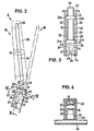
- Fig. 2, die Kopstütze nach Fig. 1 in zwei Stellungen A und B in einer Seitenansicht, wobei ihre unteren Enden in die Halterung in der Rückenlehne eingesetzt sind,
- Fig. 3, den Gegenstand der Fig. 2 in einem Längsschnitt nach Linie 111-111 und
- Fig. 4, den Gegenstand der Fig. 2 in einem Querschnitt nach Linie IV-IV.
- 1, a headrest according to the invention in a front view,
- 1 in two positions A and B in a side view, with their lower ends inserted into the holder in the backrest,
- Fig. 3, the subject of Fig. 2 in a longitudinal section along line 111-111 and
- Fig. 4, the subject of Fig. 2 in a cross section along line IV-IV.
In den Zeichnungen ist mit 10 eine Kopfstütze in ihrer Gesamtheit bezeichnet, die in der Rückenlehne 11 eines hier nicht näher dargestellten Kraftfahrzeugsitzes verankert ist. Die Kopfstütze besteht aus einem im wesentlichen U--förmigen Bügel 12, dessen zunächst trapezförmig divergierende Schenkel 13 und 14 in die parallel verlaufenden Stäbe 15 übergehen, deren freie Enden 16 in die Rückenlehne 11 hineinreichen und dort in weiter unten noch näher beschriebener Weise verankert sind. Die Schenkel 13 und 14 sind durch eine Traverse 17 und die Stäbe 15 durch eine Traverse 18 in Querrichtung ausgesteift, wobei die Traversen 17 und 18 mit dem Bügel verlötet oder verschweißt sind.In the drawings, 10 denotes a headrest in its entirety, which is anchored in the
Der Bügel 12 kann aus einem vollen Stab bestehen. Im vorliegenden Ausführungsbeispiel wird er von einem Rohr gebildet. Alle Teile des Bügels mit Ausnahme der Stabenden 16 sind mit einer Polsterung 19 ummantelt, die jedoch zwischen dem oberen Holm 20 und der Traverse 17 einerseits und zwischen den Traversen 17 und 18 anderseits den Durchblick frei läßt.The
In jedem der beiden freien Stabenden 16 sind koplanar und im Abstand voneinander je zwei Zapfen. 21 und 22 angeordnet, die in das Stab- bzw. Rohrende 16 durchdringenden Bohrungen sitzen und deren Enden 21 a, 21 b bzw. 22a, 22b über den Außenumfang des Stabes 16 vorstehen. Über das untere Ende 16 des Stabes 15 ist eine im Querschnitt U-förmige Halte- und Führungshülse 23 geschoben, die an ihrer Unterseite 24 durch einen nach innen gebogenen Teil mindestens teilweise verschlossen ist, der einen Vorsprung 25 bildet. Gegen diesen Vorsprung 25 legt sich das eine Ende 26 einer Rastfeder 27 an, deren anderes Ende 28 ins Innere des Stabendes 16 hineinragt und sich gegen den Zapfen 21 abstützt, der sich im geringen Abstand vom unteren Ende 34 des Stabes 15 befindet.In each of the two
Die Führungshülse 23 hat in ihren einander gegenüberliegenden Seitenwänden 29 und 30 im unteren Teil einander gegenüberliegende Langlöcher 31 und 32, die sich parallel zur Längsachse 33 des Stabes 15 und der Führungshülse 16 erstrecken und in die die vorspringenden Enden 21 und 21b des einen Zapfens 21 eingreifen.The
Oberhalb der Langlöcher 31 und 32 sind im Bereich des anderen Zapfens 22 in den Seitenwänden 29 und 30 der Führungshülse 23 Ausnehmungen 35 vorgesehen, die von V-förmigen Nuten 36 gebildet werden, deren einer nächst der Vorderseite 37 angeordneter Schenkel 38 parallel zur Längsachse 33 der Führungshülse 23 verläuft und eine Raste 39 für den Zapfen 22 bildet. Die zweite Raste 40 bildet dann der zweite, schräg zur Achse verlaufende Schenkel 41 der V-förmigen Nute 36 (Fig. 2).Above the
Jede Führungshülse 23 wird von einem Kunststoffrohr 42 umschlossen, das an seiner Oberseite mit einer Abdeckung 43 versehen ist, die am Umfang des Stabendes 16 dicht angliegt und die Führungshülse 23 an ihrer Oberseite abdeckt.Each
Wie insbesondere aus den Fig. 2, 3 und 4 hervorgeht, sind die mit der Führungshülse 23 und dem Kunststoffrohr 42 versehenen Stabenden in hierfür vorgesehene Halterungen 44 eingeschoben, die am Lehnenrahmen 45 festgeschweißt sind.As can be seen in particular from FIGS. 2, 3 and 4, the rod ends provided with the
Die Erfindung ist nicht auf das Ausführungsbeispiel beschränkt. Beispielsweise kann der Verstellmechanismus auch bei solchen Kopfstützen angewendet werden, die vollgepolstert sind und keinen Durchblick gewähren. Es ist auch möglich, anstelle der Rastfeder eine Zugfeder vorzusehen, welche die Kopfstütze in der Führungshülse in den nach unten offenen Rasten nach oben zieht. Schließlich ist es auch möglich, anstelle der einseitig offenen Führungshülse ein geschlossenes Führungsrohr zu verwenden, das nicht nur einen quadratischen, sondern auch einen kreisrunden Querschnitt haben kann. Außerdem ist es möglich, die Langlöcher und V-förmigen Nuten in ihrer Anordnung derart zu vertauschen, daß sich die Langlöcher oben im Bereich des Zapfens 22 und die V-förmige Nute unten im Bereich des Zapfens 21 befindet. Diese Ausgestaltung hat den Vorteil, daß der Schwenkpunkt der Kopfstütze in die Nähe des oberen Randes des Rückenlehnenrahmens verlegt wird, was dann besonders zweckmäßig ist, wenn die Durchtrittsöffnung für das Stabende in der Polsterung der Rückenlehne möglichst klein geharten werden soll. In diesem Falle ist es zweckmäßig, den Vorsprung im Inneren der Führungshülse 23 etwa in der Mitte der Führungshülse anzuordnen und die Rastfeder dann gegen diesen Vorsprung und gegen den oberen Zapfen abzustützen. Auch eine solche Ausführungsform fällt mit in den Rahmen der Erfindung.The invention is not restricted to the exemplary embodiment. For example, the adjustment mechanism can also be used with those headrests that are fully upholstered and do not allow a clear view. It is also possible to provide a tension spring instead of the detent spring, which pulls the headrest in the guide sleeve upwards in the detents which are open at the bottom. Finally, it is also possible to use a closed guide tube instead of the guide sleeve which is open on one side and which can have not only a square but also a circular cross section. It is also possible to interchange the elongated holes and V-shaped grooves in their arrangement such that the elongated holes are located at the top in the region of the
Claims (5)
Applications Claiming Priority (2)
| Application Number | Priority Date | Filing Date | Title |
|---|---|---|---|
| DE2755411 | 1977-12-13 | ||
| DE19772755411 DE2755411A1 (en) | 1977-12-13 | 1977-12-13 | HEADREST, IN PARTICULAR FOR VEHICLE SEATS |
Publications (2)
| Publication Number | Publication Date |
|---|---|
| EP0002730A1 EP0002730A1 (en) | 1979-07-11 |
| EP0002730B1 true EP0002730B1 (en) | 1981-02-18 |
Family
ID=6025972
Family Applications (1)
| Application Number | Title | Priority Date | Filing Date |
|---|---|---|---|
| EP78101668A Expired EP0002730B1 (en) | 1977-12-13 | 1978-12-13 | Head rest, in particular for vehicle seats |
Country Status (2)
| Country | Link |
|---|---|
| EP (1) | EP0002730B1 (en) |
| DE (1) | DE2755411A1 (en) |
Families Citing this family (4)
| Publication number | Priority date | Publication date | Assignee | Title |
|---|---|---|---|---|
| US4674792A (en) * | 1985-06-07 | 1987-06-23 | Ikeda Bussan Co, Ltd. | Position adjustable see-through headrest |
| FR2717428B1 (en) * | 1994-03-16 | 1996-05-15 | Faure France Bertrand | Improvements to vehicle seats with reclining headrest. |
| JPH08266368A (en) * | 1995-03-24 | 1996-10-15 | R Schmidt Gmbh | Head supporting device for automobile |
| DE10257227B4 (en) * | 2002-12-07 | 2010-08-05 | GM Global Technology Operations, Inc., Detroit | Vehicle seat and adjusting device for a vehicle seat |
-
1977
- 1977-12-13 DE DE19772755411 patent/DE2755411A1/en not_active Withdrawn
-
1978
- 1978-12-13 EP EP78101668A patent/EP0002730B1/en not_active Expired
Also Published As
| Publication number | Publication date |
|---|---|
| DE2755411A1 (en) | 1979-06-21 |
| EP0002730A1 (en) | 1979-07-11 |
Similar Documents
| Publication | Publication Date | Title |
|---|---|---|
| DE3637362C2 (en) | ||
| DE3021191C2 (en) | ||
| DE102004017688B4 (en) | Headrest for automobile seats | |
| DE102012012850B4 (en) | vehicle seat | |
| EP0236891B1 (en) | Folding furniture | |
| DE3115972A1 (en) | "VEHICLE SEAT WITH INDIVIDUALLY ADJUSTABLE FRONT THigh SUPPORT" | |
| DE102005055337A1 (en) | Spring-loaded headrest | |
| DE2633044A1 (en) | BACKREST HEIGHT ADJUSTMENT DEVICE | |
| DE19755524C1 (en) | Child-seat for motor vehicles | |
| DE19620872A1 (en) | Front car seat with adjustable length and height | |
| DE3529957C2 (en) | ||
| DE4040514C2 (en) | Vehicle seat arrangement | |
| DE3223649C2 (en) | ||
| DE102007012429B4 (en) | Automotive seat | |
| DE2910448C2 (en) | ||
| DE102010038250B4 (en) | Headrest with longitudinal adjustment | |
| DE4126518C2 (en) | Vehicle seat | |
| DE102004054165B4 (en) | Motor vehicle seat with adjustable backrest | |
| EP0002730B1 (en) | Head rest, in particular for vehicle seats | |
| DE2816601A1 (en) | Passenger vehicle seat folding table - has shaft and guides in out of use position holding table top secure | |
| DE10133132A1 (en) | Arm rest for office chair comprises support column with plate at its base, allowing it to be attached to chair seat, and upholstered arm rest pad mounted so that it can slide forward to adjust distance between its front end and seat | |
| DE102007036880A1 (en) | Vehicle seat for use in rear tier of motor vehicle, has lower panel displaced relative to upper panel and arranged below upper panel, where lower and upper panels are adjusted relative to each other during stroke movement of seat part | |
| DE102006033784B4 (en) | Child safety seat | |
| DE3927379C1 (en) | ||
| DE3312598A1 (en) | VEHICLE SEAT |
Legal Events
| Date | Code | Title | Description |
|---|---|---|---|
| PUAI | Public reference made under article 153(3) epc to a published international application that has entered the european phase |
Free format text: ORIGINAL CODE: 0009012 |
|
| AK | Designated contracting states |
Designated state(s): BE FR GB IT SE |
|
| 17P | Request for examination filed | ||
| ITF | It: translation for a ep patent filed |
Owner name: STUDIO INGG. FISCHETTI & WEBER |
|
| GRAA | (expected) grant |
Free format text: ORIGINAL CODE: 0009210 |
|
| AK | Designated contracting states |
Designated state(s): BE FR GB IT SE |
|
| PGFP | Annual fee paid to national office [announced via postgrant information from national office to epo] |
Ref country code: SE Payment date: 19821231 Year of fee payment: 5 Ref country code: FR Payment date: 19821231 Year of fee payment: 5 Ref country code: BE Payment date: 19821231 Year of fee payment: 5 |
|
| PG25 | Lapsed in a contracting state [announced via postgrant information from national office to epo] |
Ref country code: SE Effective date: 19831214 |
|
| PG25 | Lapsed in a contracting state [announced via postgrant information from national office to epo] |
Ref country code: BE Effective date: 19831231 |
|
| GBPC | Gb: european patent ceased through non-payment of renewal fee | ||
| PG25 | Lapsed in a contracting state [announced via postgrant information from national office to epo] |
Ref country code: FR Free format text: LAPSE BECAUSE OF NON-PAYMENT OF DUE FEES Effective date: 19840831 |
|
| REG | Reference to a national code |
Ref country code: FR Ref legal event code: ST |
|
| PG25 | Lapsed in a contracting state [announced via postgrant information from national office to epo] |
Ref country code: GB Effective date: 19881117 |
|
| EUG | Se: european patent has lapsed |
Ref document number: 78101668.8 Effective date: 19850605 |
|
| PLBE | No opposition filed within time limit |
Free format text: ORIGINAL CODE: 0009261 |
|
| STAA | Information on the status of an ep patent application or granted ep patent |
Free format text: STATUS: NO OPPOSITION FILED WITHIN TIME LIMIT |