EP0002061B2 - Abtastumformer für Ultraschall-Sektorabtasteinrichtung und Verfahren - Google Patents
Abtastumformer für Ultraschall-Sektorabtasteinrichtung und Verfahren Download PDFInfo
- Publication number
- EP0002061B2 EP0002061B2 EP19780101387 EP78101387A EP0002061B2 EP 0002061 B2 EP0002061 B2 EP 0002061B2 EP 19780101387 EP19780101387 EP 19780101387 EP 78101387 A EP78101387 A EP 78101387A EP 0002061 B2 EP0002061 B2 EP 0002061B2
- Authority
- EP
- European Patent Office
- Prior art keywords
- scan
- data
- sector
- echo
- line
- Prior art date
- Legal status (The legal status is an assumption and is not a legal conclusion. Google has not performed a legal analysis and makes no representation as to the accuracy of the status listed.)
- Expired
Links
Images


Classifications
-
- G—PHYSICS
- G01—MEASURING; TESTING
- G01S—RADIO DIRECTION-FINDING; RADIO NAVIGATION; DETERMINING DISTANCE OR VELOCITY BY USE OF RADIO WAVES; LOCATING OR PRESENCE-DETECTING BY USE OF THE REFLECTION OR RERADIATION OF RADIO WAVES; ANALOGOUS ARRANGEMENTS USING OTHER WAVES
- G01S7/00—Details of systems according to groups G01S13/00, G01S15/00, G01S17/00
- G01S7/52—Details of systems according to groups G01S13/00, G01S15/00, G01S17/00 of systems according to group G01S15/00
- G01S7/52017—Details of systems according to groups G01S13/00, G01S15/00, G01S17/00 of systems according to group G01S15/00 particularly adapted to short-range imaging
- G01S7/52023—Details of receivers
- G01S7/52044—Scan converters
-
- A—HUMAN NECESSITIES
- A61—MEDICAL OR VETERINARY SCIENCE; HYGIENE
- A61B—DIAGNOSIS; SURGERY; IDENTIFICATION
- A61B8/00—Diagnosis using ultrasonic, sonic or infrasonic waves
Definitions
- the invention relates to a combination of a scan converter for the conversion of ultrasonic echo signals in sector scan format to raster format for display and an ultrasonic imaging system wherein echo samples are sequentially obtained along scan lines which are angularly spaced and distributed on either side of a line normal to the observed object, the echo samples are converted from analog representation to digital representation, the digital representations are stored in a memory matrix accommodating such digital representations in rows and columns, the memory matrix is connected with an output buffer storage register, and the sampled output of said output buffer storage register is converted from digital representation to analog representation and fed to display apparatus, wherein echoes are sampled at a rate which varies with the scan angle so that corresponding samples are linearly aligned on respective lines perpendicular to the line normal to the observed object, the data from the scanning operation is stored in the memory matrix on a column by column basis and read out from the memory matrix on a row by row basis, wherein read out takes place at a rate which is dependent on the width of the scan sector at the raster line being read out and
- the single-sector scanner ultrasonic imager is a real time imaging system having a linear transducer array (as depicted in Fig. 1). To make a sector scan the elemental transducers are excited in linear time sequence to generate angulated acoustic beams at many different angles relative to the normal to the array at the midpoint.
- Echoes returning from targets in the direction of the transmitted acoustic beam arrive at the transducer elements at different times 'necessitating relative delaying of the received echo electrical signals by different amounts to focus the received echoes, and the delayed echo signals are summed before being fed to the scan converter.
- the angulated transmitted beam is rotated by equal scan angle increments, and in the scan converter the focused echo signals are sampled at equal time intervals so that the data samples are along arcs concentric to the origin point.
- the cathode ray tube is a rectangular grid type display. The function of the scan converter is therefore relatively complex and a picture of uneven quality often results, worsened by the tendency of the eye to focus on uneven areas.
- a single-sector steered beam cardiac scanner with a TV monitor display is described by Thurstone and von Ramm in "A New Ultrasound Imaging Technique Employing Two-Dimensional Electronic Beam Steering", Acoustical Holography, Vol. 5, 1974, Plenum Press, New York, pp. 249-259.
- the present invention is applicable also to the multisector or "walking beam" ultrasonic imaging system having a longer linear transducer array for producing a set of sector scans with the origin points of the sequential sector scans displaced longitudinally along the array.
- the input sector geometry is somewhat changed.
- the scan angles of the acoustic scan lines are chosen so that they intersect a lateral line at equal increments, i.e., the scan angles have equal tangent increments.
- a scan converter for the conversion of ultrasonic echo signals in sector scan format to raster format for display and an ultrasonic imaging system wherein echo samples are sequentially obtained along scan lines which are angularly spaced and distributed on either side of a line normal to the observed object, the echo samples are converted from analog representation to digital representation, the digital representations are stored in a memory matrix accommodating such digital representations in rows and columns, the memory matrix is connected with an output buffer storage register, and the sampled output of said output buffer storage register is converted from digital representation to analog representation and fed to display apparatus, wherein echo scan sampling is carried out along scan lines angularly spaced one from the other by an amount corresponding to equal tangent increments when the angles are referred to the line normal to the observed object so that the acoustic scan lines intersect a lateral line perpendicular to the normal line at equal increments and echoes are sampled at a rate which varies with the scan angle so that corresponding samples are linearly aligned on lines per
- the echo sampling is performed along a sequence of scan lines each angularly spaced one from the other by an amount corresponding to equal tangential increments when the angles are referred to a line normal to the observed object so that acoustic scan lines intersect a lateral line perpendicular to said normal line at equal increments and said sampling is performed at a rate which varies with the scan angle so that corresponding samples are linearly aligned on lines perpendicular to said line normal to the observed object, the scan derived data are stored in a memory matrix on a column by column basis and such data are read out from said memory matrix on a row by row basis at a frequency dependent on the width of the scan sector line at the raster line and with a time delay dependent on the separation of the edge of the sector from a reference line at the raster line so that the sector geometry is obtained.
- Memory is required only in the amount needed to store the input digital echo data. For instance, a 32K memory is sufficient for a conventional TV raster of 400 lines with 300 picture elements each or 120K pixels.
- the memory is operated in burst mode with alternate reading in and reading out, and the memory is divided into segments to facilitate writing of echo data in parallel into the segments and reading out in parallel into a like number of output buffer shift registers. Some sampling points can be skipped to avoid high rates of clocking out data in parallel from the shift registers. These data will be "filled in” by the action of the low pass filter at the output.
- the digital scan conversion apparatus and method of converting ultrasound echo signals for raster scan display are described with regard to real time single-sector and multi-sector cardiology and laminography imaging systems.
- the format of the sector is somewhat changed.
- the scan angles are chosen so that the acoustic scan lines intersect a lateral line at equal increments, and along each of these scan lines a focused received echo signal is sampled at a rate that varies with the scan angle.
- Corresponding data samples are taken at the same value of the z-axis coordinate, whereby the samples are arranged in a number of rows parallel to one another and the linear transducer array.
- Successively sampled scan lines are buffered and stored in a digital memory in adjacent columns of a row-column oriented memory.
- memory is required only in the amount needed to store the input data, and the only storage call locations that are unused are those intentionally skipped where the input data near the sector origin is too dense to be processed at reasonable rates and viewed as individual pixels.
- all data samples in a row and corresponding to a single value of the z-axis coordinate are read into a shift register buffer, which is then clocked out at a rate corresponding to the sector width at that value of z.
- These data are fed to an digital-to-analog converter, whose output is low pass filtered and presented to the display. Modifications of the foregoing preferred embodiment of the scan converter will be discussed subsequently.
- the single-sector steered beam ultrasonic scanner in Fig. 1 has a linear transducer array 10 comprised of equally spaced elementary transducers 11 which are energized by excitation pulses 12 in a linear time sequence to form an ultrasound beam 13 and direct the beam in a preselected azimuth direction to transmit a pulse of ultrasound.
- the angle ⁇ at one side of the normal is changed by increments.
- the timing of excitation pulses 12 is reversed so that the bottom transducer in Fig.
- the linear transducer array is also known as a phased array. For further information refer to "Electronic Scanning of Focused Arrays" by V. G. Welsby, Journal of Sound Vibration (1968), Vol. 8, No. 3, pps. 390-394.
- the system For real time imaging at a typical frame rate of 30 frames per second, the system also requires a television monitor on which the total image is built up line by line from the scan converter memory. From the foregoing description, it is seen that an electronically controlled, steered ultrasound beam is generated that is capable of oscillating or rotating motion about the sector origin at the midpoint of the linear transducer array. For each transmitted steered ultrasound beam, there is a corresponding focused received echo electrical signal which is fed to the digital scan converter and is data for the corresponding image line. A single sector image depicting a tomographic slice of the insonified object region is displayed in real time on the screen of the television monitor. This is further explained in detail later with regard to Fig. 7.
- the single-sector scanner has both industrial and medical applications, and is especially advantageous in medical diagnostics for cardiology and laminography.
- linear transducer array 10 is manually held against the patient's chest wall while observing the image on the cathode ray tube, and its position is changed until the desired portion of the heart is imaged.
- a frame rate of at least 30 frames per second is needed to prevent blurring of the image due to heart motion. Assuming that a maximum image depth of 20 centimeters is required or a round trip of 40 centimeters, and that the velocity of sound in tissue is 150,000 centimeters per second, the rate of generating steered acoustic beams is limited to about 3,000 per second.
- Fig. 2 shows the format of the input sector geometry according to the invention by which the physical locations of the input echo data to the scan converter are related to those of the output data of the scan converter in a simple way compatible with display along a conventional television raster.
- Acoustic scan lines are indicated by numbers 1-11, and echo data samples along the scan lines are illustrated as solid dots and indicated by letters a-r.
- the scan angles 8 on either side of the normal through origin point O are chosen to have equal tangent increments, and thus the acoustic scan lines intersect a lateral line perpendicular to the normal at equal increments.
- the echo amplitude signal is sampled at a rate which varies with the cosine of the angle of the scan line or, in other words, which varies with the scan angle so that corresponding samples from adjacent scan lines are linearly aligned on the lateral lines.
- the echo signal is sampled at a rate that varies with the scan angle so that corresponding samples are taken at the same value of the z-axis coordinate.
- the echo data samples are arranged in rows or raster lines parallel to one another and the linear transducer array, data samples in three of the raster lines are circled.
- each raster line the echo data samples are equally spaced, and in the z direction the raster lines are also equally spaced. For small values of z near the sector origin point 0, where the data samples come very close together, it is permissible to skip over some of the samples provided the actual sample rate stays above the Nyquist limit.
- the echo data samples are buffered and stored in a digital memory having a matrix of storage cell locations in columns and rows.
- Fig. 3 shows a random access memory 15 preferably made with MOS (metal oxide semiconductor) field effect transistors or bipolar transistors, and in such memories storage cell locations are accessed for the writing in and reading out of echo data by the coincidence of signals on X select lines 16 and Y select lines 17.
- Digitized echo data samples along successive scan lines 1-11 are stored in adjacent columns of random access memory 15, and a typical pattern of stored data is depicted by solid dots.
- the sequence of accessing memory columns for the storage of echo data follows the sequence of generating transmitted acoustic beams.
- one sequence is that transmitted beam 1 is produced and the time delays progressively changed to rotate the transmitted beam in the clockwise direction and produce beams 2-6, then transmitted beam 11 at the other side of the normal is generated and the time delays progressively changed to rotate the beam in a counterclockwise direction and produce beams 10-7.
- the density of stored echo data along raster lines ar increases with distance from the sector origin point, and vacant storage cell locations are intentionally skipped to keep readout of the output data from the scan converter within reasonable rates. With this exception, the entire memory is available for the storage of echo data.
- Fig. 4 The post-processing electronics is illustrated in simplified form in Fig. 4. Assuming that readout from memory begins at raster line or row r, the data samples are read into a buffer storage device such as an n-stage shift register 20. Data is clocked out of shift register 20 to an output digital-to-analog converter 21 at a variable rate corresponding to the width of the sector at that raster line or value of z (see Fig. 2).
- the control circuitry 22 In addition to varying the shift register clocks, so that the sector geometry is obtained, it is also necessary for the control circuitry 22 to delay the start of the clock pulses by varying amounts on each raster line. As readout from memory proceeds from raster line r toward raster line a, the frequency of clock pulses increases and the time delay also increases, which is dependent on the location of the edge of the sector at the row or raster line being read out from a reference line such as the edge of the television screen.
- the clock rate can reach a maximum and can be approximately the same at raster lines near the sector origin, made possible by skipping input sampling points.
- the stream of echo data is presented to a low pass filter 22 before being fed out as a video signal or Z control for varying the electron beam intensity of the cathode ray tube.
- the purpose of filtering is to smooth out the step staircase function at the DAC output. Echo data for a raster line is clocked out of shift register 20 at TV rates, and in a conventional television monitor the time for the electron beam to scan across a single line and retrace itself is 63 microseconds.
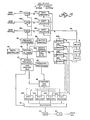
- Fig. 5 The preferred embodiment in Fig. 5 of the complete digital scan converter can now be explained.
- Input analog-to-digital converters 25-25c sample the respective input amplitude signals under control of a frequency synthesizer 26 at a rate which varies with the cosine of the angle of the scan line. It is permissible for frequency synthesizer 26 to operate on the basis of multiplying a base frequency by a rational fraction, because some frequency error can be tolerated. This means that the data sampling points in Fig.
- the digitized data samples having 8 bits each in the example being given, are fed to a first-in-first-out input data buffer such as shift registers 27a-27c. Data samples stored temporarily in the three shift registers are clocked out successiveively by a buffer control 28 into a common memory input bus 29.
- the random access memory can be made from the type 2102 Solid State Memory Chip available commercially from a number of manufacturers including Intel Corp. and National Semiconductor Corp. This is a 32Kx8-bit memory divided into four 8Kx8 bit memory banks or segments 30A-30D, each with a matrix of 45x180 storage cell locations.
- the cycle time for this memory is 450 microseconds, and to achieve the object of real time imaging four echo data samples, one per segment, are written into memory simultaneously and four data samples are read out simultaneously. Improved operation is attained by making one-half of the memory cycles available for read in purposes and one-half for readout which occurs in apparently simultaneous manner.
- input bus 29 is connected directly to segment 30A, through one unit delay element 31 to segment 30B, through two such delay elements to segment 30C, and through three of the delay elements to - segment 30D.
- the first three samples are delayed by variable amounts and the last has a zero delay so that the four samples can be written into the accessed storage cell locations atthe same time.
- the available 30 microseconds for read in as many data samples as can be processed during this time are entered into the four memory banks. Whenever data for a complete scan line is emptied out of one of shift registers 27a-27c, data is clocked out of the next input shift register in sequence.
- the sequence of storage cell location addresses that controls where each sampling point is stored, as well as the readout sequence, are stored in memory address sequence read- only memories 32.
- ROMs 32, buffer control 28, and frequency synthesizer 26 are controlled by a control and timing unit 33 which can be part of the master digital controller in Fig. 7.
- the memory addresses read out of ROMs 32 is 56-bit data, 14 bits for each memory segment.
- Stored echo amplitude data is read out simultaneously from memory segments 30A-30D into four separate shift registers 34A-34D, one per memory segment. These can be 64x8 bit shift registers, To clock out data samples temporarily stored in the shift registers at a rate corresponding to the width of the sector at the raster line being read out, an output frequency synthesizer or variable clock 35 is provided for generating clock pulses which are gated at the proper time to shift registers 34A-34D by counter and gate circuitry 36.
- the clock rate at raster line r is, for instance, 6 MHz and at line h is 12 MHz
- the counters delay the start of the clock pulses by varying amounts on each raster line, dependent on the distance from the edge of the screen to the beginning of the raster line being read out, and are operative to count down and open a gate at a predetermined count to let the clock pulses through and then close the gate at another point as the count continues.
- the counter is reset, ready for the next cycle of operation.
- the parameters controlling the frequency synthesizer and the counters and gates are loaded from output frequency synthesizer and counter read- only memories 37 that in turn are controlled by control and timing unit 33.
- Digital data samples read out in parallel from the four shift registers are presented to a multiplexer 38, and at the output the data samples are in serial groups of four containing one sample from each shift register. After the data samples are passed through digital-to-analog converter 39 and low pass filter 40, the resulting video signal is fed to the cathode ray tube.
- Fig. 6 the pattern of storing echo data samples in the memory segments or banks is shown in Fig. 6.
- raster line j it is seen that the sequence across the row is A, B, C, D, A, etc. This is the proper sequence for reading out stored data in parallel from memory segments 30A-30D. To get this arrangement of stored data, it is necessary to process the memory addressing of the memory segments from one scan line to the next.
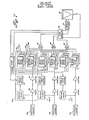
- Fig. 7 is a system block diagram of the single sector scanner ultrasonic imager incorporating the digital scan converter.
- the linear transducer array is illustrated with only three transducer elements 43a-43c, but in practice the array has a larger number of transducer elements.
- the three transmitting and receiving channels 44a-44c are each comprised by level and timing control circuitry 45 under the control of master digital controller 46 for determining the level and timing of a transmit pulse generated by transmit pulser 47 and applied to one of the transducer elements.
- the receiving channel for processing the received echo electrical signal is comprised of a preamplifier 48 having a limiter to protect the sensitive preamplifier inputs from the high transmitting voltage, and a compression amplifier 49 to reduce the larger dynamic acoustic range to the smaller range a cathode ray tube display device can handle.
- the amplifier echo signal is next fed in parallel to three digitally selected analog delay circuits 50, 50' and 50" having an associated delay select switch matrix 51,51' and 51" which, under the control of digital controller 46, selects the delay element or elements to focus the echo signal in the three delay channels. For each transmitted acoustic beam, it is recalled, there are three different focused echo signals within the lobe or angle of the transmitted beam.
- the other two receiving channels are identical except for the values of the time delays employed.
- Digital controller 46 can take various forms and can be hard-wired logic circuit, but is preferably a properly programmed minicomputer or microcomputer.
- transducer excitation pulses are generated by the three transmitting channels in time sequence to steer the generated ultrasound beam and control the scan angle.
- the received echo signals are time delayed by different preselected amounts in the three receiving channels, and in the three delay channels within each of the receiving channels.
- the delayed echo signals from the three analog delay circuits 50, one per receiving channel are fed to a summing amplifier 52; and the delayed echo signals from the three delay circuits 50' are summed by summing amplifier 52', and those from delay circuits 50" are summed by summing amplifier 52".
- the three focused ultrasound echo signals at the summing amplifier outputs are now processed through digital scan converter 53 to convert the sector scan format to raster scan format as here described.
- the scan converter also controls sweep drivers 54 and the generated X and Y deflection signals for cathode ray tube 55 on which is displayed, in real time, the single sector image.
- the order of generating transmitted acoustic beams is fixed and is preset by digital controller 46, which supplies coordinating information to the scan converter.
- the components of the digital scan converter can be standard integrated circuits or conventional circuitry as is presently known in the art. With appropriate modifications that will be apparent, the scan conversion apparatus and method of converting ultrasound echo signals are also applicable to a multisector scanner ultrasonic imaging system. Also, the digital echo output data can be transferred to a storage medium like floppy disks for permanent storage for display at a later-time.
- the method of scan conversion comprises generating input digital echo data representing received echo amplitudes at sampling points along scan lines angulated at angles on either side of the normal having substantially equal tangent increments, the sampling points on each scan line being taken at the rate which varies with the cosine of the scan angle whereby the sampling points are along lateral raster lines perpendicular to the normal.
- Digital echo data is written scan line by scan line into a memory having a matrix of storage cell locations in columns and rows, but the stored data is read out of memory raster line by raster line.
- the read-out digital echo data is then processed to generate output data at a rate dependent upon the width of the sector at the raster line and delayed in time dependent on the location of the edge of the sector from a reference line.
- Memory is required only in the amount needed to store the input data.
- a 32 Kx8 bit memory provides a display covering approximately 400 lines of 300 picture elements each (120 K).
Claims (9)
Applications Claiming Priority (2)
| Application Number | Priority Date | Filing Date | Title |
|---|---|---|---|
| US85334777A | 1977-11-21 | 1977-11-21 | |
| US853347 | 1977-11-21 |
Publications (3)
| Publication Number | Publication Date |
|---|---|
| EP0002061A1 EP0002061A1 (de) | 1979-05-30 |
| EP0002061B1 EP0002061B1 (de) | 1982-05-05 |
| EP0002061B2 true EP0002061B2 (de) | 1986-11-26 |
Family
ID=25315790
Family Applications (1)
| Application Number | Title | Priority Date | Filing Date |
|---|---|---|---|
| EP19780101387 Expired EP0002061B2 (de) | 1977-11-21 | 1978-11-17 | Abtastumformer für Ultraschall-Sektorabtasteinrichtung und Verfahren |
Country Status (3)
| Country | Link |
|---|---|
| EP (1) | EP0002061B2 (de) |
| JP (1) | JPS5485587A (de) |
| DE (1) | DE2861793D1 (de) |
Families Citing this family (14)
| Publication number | Priority date | Publication date | Assignee | Title |
|---|---|---|---|---|
| US4275415A (en) * | 1978-11-13 | 1981-06-23 | Litton Industrial Products, Inc. | Scan converter |
| JPS5578947A (en) * | 1978-12-08 | 1980-06-14 | Matsushita Electric Ind Co Ltd | Method of displaying ultrasoniccwave diagnosis device |
| DE2942049A1 (de) * | 1979-10-17 | 1981-05-21 | Siemens AG, 1000 Berlin und 8000 München | Vorrichtung zur ultraschallabtastung |
| JPS5672857A (en) * | 1979-11-16 | 1981-06-17 | Matsushita Electric Ind Co Ltd | Method of scanning ultrasonic diagnosing device |
| JPS56109649A (en) * | 1980-02-05 | 1981-08-31 | Matsushita Electric Ind Co Ltd | Ultrasonic diagnosing device |
| FR2479531A1 (fr) * | 1980-03-28 | 1981-10-02 | Cgr Ultrasonic | Dispositif de traitement et de memorisation numerique et echographe a balayage comportant un tel dispositif |
| DE3017027A1 (de) * | 1980-05-02 | 1983-01-20 | Siemens AG, 1000 Berlin und 8000 München | Vorrichtung zum speichern von signalen |
| JPS6060061B2 (ja) * | 1980-10-27 | 1985-12-27 | 株式会社東芝 | 画像処理システム |
| US4387365A (en) * | 1981-05-15 | 1983-06-07 | Advanced Technology Laboratories, Inc. | Real time digital scan converter |
| US4386529A (en) * | 1981-08-07 | 1983-06-07 | General Electric Company | Method and means for improving video display image |
| FR2531783B1 (fr) * | 1982-08-13 | 1989-09-08 | Centre Nat Rech Scient | Procede et dispositif de conversion d'images obtenues par balayage sectoriel en images a balayage par lignes |
| JPS5977369A (ja) * | 1982-10-19 | 1984-05-02 | Fujitsu Ltd | 画像補間装置 |
| JP2554618B2 (ja) * | 1985-09-30 | 1996-11-13 | 株式会社東芝 | 超音波診断装置 |
| US5127409A (en) * | 1991-04-25 | 1992-07-07 | Daigle Ronald E | Ultrasound Doppler position sensing |
Family Cites Families (6)
| Publication number | Priority date | Publication date | Assignee | Title |
|---|---|---|---|---|
| US3653044A (en) * | 1969-09-22 | 1972-03-28 | Kaiser Aerospace & Electronics | Display system for providing radar plan position information on a raster display |
| US3827027A (en) * | 1971-09-22 | 1974-07-30 | Texas Instruments Inc | Method and apparatus for producing variable formats from a digital memory |
| US3765018A (en) * | 1972-06-02 | 1973-10-09 | Hughes Aircraft Co | Digital scan converter |
| US3858085A (en) * | 1973-07-09 | 1974-12-31 | Us Navy | Digital raster generator |
| NL7604678A (nl) * | 1975-05-07 | 1976-11-09 | Hoffmann La Roche | Aftastomzetter. |
| IL49825A0 (en) * | 1976-04-05 | 1976-08-31 | Varian Associates | Display and recording system for ultrasonic diagnosis |
-
1978
- 1978-11-17 DE DE7878101387T patent/DE2861793D1/de not_active Expired
- 1978-11-17 EP EP19780101387 patent/EP0002061B2/de not_active Expired
- 1978-11-21 JP JP14292478A patent/JPS5485587A/ja active Pending
Also Published As
| Publication number | Publication date |
|---|---|
| DE2861793D1 (en) | 1982-06-24 |
| JPS5485587A (en) | 1979-07-07 |
| EP0002061A1 (de) | 1979-05-30 |
| EP0002061B1 (de) | 1982-05-05 |
Similar Documents
| Publication | Publication Date | Title |
|---|---|---|
| US4245250A (en) | Scan converter for ultrasonic sector scanner | |
| US4159462A (en) | Ultrasonic multi-sector scanner | |
| US4167753A (en) | Peak detecting digital scan converter | |
| US4180790A (en) | Dynamic array aperture and focus control for ultrasonic imaging systems | |
| US4611494A (en) | Ultrasonic imaging apparatus using digital control | |
| US4596145A (en) | Acoustic orthoscopic imaging system | |
| EP0002061B2 (de) | Abtastumformer für Ultraschall-Sektorabtasteinrichtung und Verfahren | |
| JP3759769B2 (ja) | 超音波ビームフォーマ | |
| US4127034A (en) | Digital rectilinear ultrasonic imaging system | |
| US4212072A (en) | Digital scan converter with programmable transfer function | |
| US4733562A (en) | Method and apparatus for ultrasonic scanning of an object | |
| US4694434A (en) | Three-dimensional imaging system | |
| US4214269A (en) | Real time digital scan converter | |
| US5203335A (en) | Phased array ultrasonic beam forming using oversampled A/D converters | |
| US6126602A (en) | Phased array acoustic systems with intra-group processors | |
| EP0158920B1 (de) | Gerät zur Abtastumsetzung | |
| US4815047A (en) | Synthetic focus annular array transducer | |
| US4368643A (en) | Ultrasonic imaging by radial scan beams emanating from a hypothetical point located behind linear transducer array | |
| CA1238405A (en) | Curvilinear array ultrasonic scanner | |
| US4423737A (en) | Combination tomographic and cardiographic ultrasonic imaging method and system | |
| US4542746A (en) | Ultrasonic diagnostic apparatus | |
| US4409982A (en) | Ultrasonic step scanning utilizing curvilinear transducer array | |
| US20100022883A1 (en) | Ultrasonic diagnostic apparatus | |
| Corl et al. | A digital synthetic focus acoustic imaging system | |
| US4553437A (en) | Hybrid non-invasive ultrasonic imaging system |
Legal Events
| Date | Code | Title | Description |
|---|---|---|---|
| PUAI | Public reference made under article 153(3) epc to a published international application that has entered the european phase |
Free format text: ORIGINAL CODE: 0009012 |
|
| AK | Designated contracting states |
Designated state(s): DE FR GB NL |
|
| 17P | Request for examination filed | ||
| GRAA | (expected) grant |
Free format text: ORIGINAL CODE: 0009210 |
|
| AK | Designated contracting states |
Designated state(s): DE FR GB NL |
|
| REF | Corresponds to: |
Ref document number: 2861793 Country of ref document: DE Date of ref document: 19820624 |
|
| PLBI | Opposition filed |
Free format text: ORIGINAL CODE: 0009260 |
|
| 26 | Opposition filed |
Opponent name: SIEMENS AG, BERLIN UND MUENCHEN Effective date: 19830204 |
|
| REG | Reference to a national code |
Ref country code: GB Ref legal event code: 746 |
|
| PUAH | Patent maintained in amended form |
Free format text: ORIGINAL CODE: 0009272 |
|
| STAA | Information on the status of an ep patent application or granted ep patent |
Free format text: STATUS: PATENT MAINTAINED AS AMENDED |
|
| 27A | Patent maintained in amended form |
Effective date: 19861126 |
|
| AK | Designated contracting states |
Kind code of ref document: B2 Designated state(s): DE FR GB NL |
|
| ET3 | Fr: translation filed ** decision concerning opposition | ||
| NLR2 | Nl: decision of opposition | ||
| NLR3 | Nl: receipt of modified translations in the netherlands language after an opposition procedure | ||
| REG | Reference to a national code |
Ref country code: FR Ref legal event code: DL |
|
| PGFP | Annual fee paid to national office [announced via postgrant information from national office to epo] |
Ref country code: FR Payment date: 19941013 Year of fee payment: 17 |
|
| PGFP | Annual fee paid to national office [announced via postgrant information from national office to epo] |
Ref country code: GB Payment date: 19941026 Year of fee payment: 17 |
|
| PGFP | Annual fee paid to national office [announced via postgrant information from national office to epo] |
Ref country code: NL Payment date: 19951024 Year of fee payment: 18 |
|
| PGFP | Annual fee paid to national office [announced via postgrant information from national office to epo] |
Ref country code: DE Payment date: 19951027 Year of fee payment: 18 |
|
| PG25 | Lapsed in a contracting state [announced via postgrant information from national office to epo] |
Ref country code: GB Effective date: 19951117 |
|
| GBPC | Gb: european patent ceased through non-payment of renewal fee |
Effective date: 19951117 |
|
| PG25 | Lapsed in a contracting state [announced via postgrant information from national office to epo] |
Ref country code: FR Effective date: 19960731 |
|
| REG | Reference to a national code |
Ref country code: FR Ref legal event code: ST |
|
| PG25 | Lapsed in a contracting state [announced via postgrant information from national office to epo] |
Ref country code: NL Effective date: 19970601 |
|
| NLV4 | Nl: lapsed or anulled due to non-payment of the annual fee |
Effective date: 19970601 |
|
| PG25 | Lapsed in a contracting state [announced via postgrant information from national office to epo] |
Ref country code: DE Effective date: 19970801 |