EP0001353A1 - Behälter für magnetische Speicherelemente - Google Patents
Behälter für magnetische Speicherelemente Download PDFInfo
- Publication number
- EP0001353A1 EP0001353A1 EP78300402A EP78300402A EP0001353A1 EP 0001353 A1 EP0001353 A1 EP 0001353A1 EP 78300402 A EP78300402 A EP 78300402A EP 78300402 A EP78300402 A EP 78300402A EP 0001353 A1 EP0001353 A1 EP 0001353A1
- Authority
- EP
- European Patent Office
- Prior art keywords
- covers
- container
- tray
- cover
- insert
- Prior art date
- Legal status (The legal status is an assumption and is not a legal conclusion. Google has not performed a legal analysis and makes no representation as to the accuracy of the status listed.)
- Granted
Links
Images

Classifications
-
- G—PHYSICS
- G11—INFORMATION STORAGE
- G11B—INFORMATION STORAGE BASED ON RELATIVE MOVEMENT BETWEEN RECORD CARRIER AND TRANSDUCER
- G11B33/00—Constructional parts, details or accessories not provided for in the other groups of this subclass
- G11B33/02—Cabinets; Cases; Stands; Disposition of apparatus therein or thereon
- G11B33/04—Cabinets; Cases; Stands; Disposition of apparatus therein or thereon modified to store record carriers
- G11B33/0405—Cabinets; Cases; Stands; Disposition of apparatus therein or thereon modified to store record carriers for storing discs
- G11B33/0433—Multiple disc containers
- G11B33/0438—Multiple disc containers for disc cartridges
Definitions
- the field of this invention lies within the computer, magnetic card and magnetic disk art.
- it lies within the magnetic disk and magnetic card storage art, wherein magnetic disks and magnetic cards are to be stored and/or indexed for later use within a memory drive, such as a disk drive reader or word processing typewriter.
- the disk and card storage container of this invention incorporates a pair of covers.
- One of the covers has a wall or ledge around it that serves to provide the side walls of the container when the covers are placed in overlying relationship.
- the upper cover serves the function of providing not only a cover, but also a pivotal support for a tray-like insert to be described hereinafter.
- a tray-like insert is hinged to one of the covers by means of a pintal or living hinge.
- the insert has a pair of fan tabs overlying the tray configuration that can be utilized to receive a series of disks or cards therebehind. In this manner, the tray holds the memory disks and cards in a stacked and substantially upright position.
- the tray-like insert has side walls which also serve to prevent lateral displacement of the disks or cards stored therein. When cards are to be stored, an alternative divider wall can be used between the cards.
- the fan tabs or the insert allow for a fanning or opening up of the disks or cards that are stored therein, so that their respective numbers or titles can be read.
- the entire enclosure can be formed of plastic with living hinges so that the end result is a strong durable plastic container that can be formed through a molding process to provide disk or card storage in a readily accessable form.
- this invention comprises a foldable enclosure having a tray-like insert therein for easy access to magnetic storage disks or cards.
- the invention incorporates a cover having a ledge or side wall therearound which is normally the base of the enclosure when it is in the open position.
- An upper cover is incorporated which folds in a book-like manner onto the lower cover and supports the tray-like insert.
- the insert is pivotally supported on the upper cover by means of a pintal so that it can swing backwardly and forwardly. In the closed position it can rest against the inside surface of the upper and lower covers, In the open position, it can be placed against the lower cover within the walls or ledge therearound.
- the tray-like insert has a pair of fan tabs and side walls which prevent the magnetic storage disks or cards from excessive movement or sliding therein.
- the magnetic storage disks or cards can be reviewed by merely spreading apart the tabs so as to fan through the magnetic storage disks and ascertain the number or title with respect to each one.
- the entire enclosure, including the top and bottom covers, can be folded inwardly, thereby allowing the tray-like insert to be implaced and secured therebetween.
- the top and bottom covers and side walls of the bottom cover form a complete enclosure for the magnetic storage disks or cards in the tray-like insert.
- the tray-like insert is divided by a wall to form two adjoint pockets into which the cards can be implaced.
- the foregoing enclosure is provided with living hinges between the top and bottom covers in the form of a web or binding for the enclosure, thereby making tne enclosure a flexible and readily manufactured device by means of a plastic molding or forming process.
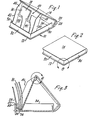
- the container 10 has a lower or first cover 12 and an upper or second cover 14.
- the two respective covers 12 and 14 are generally placed in an angular upper and horizontal lower position when the container is open.
- the container is open with a plurality of magnetic disk storage members 16 implaced therein.
- the magnetic disk storage v members 16 are the standard disks which are sometimes referred to in the common parlance of the art as floppy disks, flexible disks, or diskettes. Regardless of the type or size of disk or diskette which is uses, this container serves the function of storing them.
- the disks or diskettes are enclosed within an envelope in order to prevent dirt or dust exposure and damage to the surfaces thereof.
- the envelopes are usually provided with a label 18 which has been shown.
- the label 18 describes the material that is on the disk and can be cataloged or serializedin any partioular form in order to provide for ready access to the information stored on the disks.
- the container 10 with the upper and lower covers 12 and 14' provides for a complete enclosure of the disks 16 when the container is closed as shewn in Figure 2.
- the covers 12 and 14 are secured in place by means of a web 20 or binding.
- the web 20 or binding is formed between the covers 12 and 14 in a molding process or the covers can be joined by any other suitable means.
- the cover 12 is joined to the web or binding 20 by means of a living hinge 24 and the upper cover 14 is joined by a second living hinge 26 thereto.
- the two respective living hinges 24 and 26 allow for the web 20 or binding to be flexed backwardly and forwardly and to open in the manner as described herein.
- the web or binding 20 has an indexing member or wall 28 which allows the web when folded inwardly to be indexed with respect to a wall 30.
- the wall 30 surrounds the bottom cover 12 in a U-shaped manner having a front portion 32 and two side portions 34 and 36.
- the side portions or walls 34 and 36 serve to enclose the disk memory units when they are folded downwardly, so that the disks 16 are completely surrounded and enclosed when the covers 12 and 14 are placed in overlying relationship to each other as seen in Figure 2.
- the living hinges 24 and 26 are of sufficient flexibility and resiliency so that they will not be easily torn. At the same time, they are of sufficient flexibility and thickness to allow for long term bending and usage thereof.
- the covers 12 and 14 serve to hold and enclose a tray-like insert 40.
- the insert 40 comprises a tray-like member that has side walls 42 and 44 terminating in slanted leading surfaces respectively 46 and 48.
- the slanting leading surfaces 46 and 48 provide easy folding movement over the leading edge of the wall 32 so that it does not bind thereon when the container is being folded together.
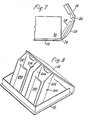
- the tray or insert 40 is formed with two openings 50 and 52 that are surrounded by an M-shaped web 54.
- the M-shaped web 54 has a lower surface attached to the bottom or end of the tray 56 which serves to allow the disks to rest thereon.
- a pair of fan tabs 58 and 60 are connected to the bottom 56 and terminate in a rounded or smooth surface.
- the fan tabs 58 and 60 are flexible and bend from their ends to where they are attached to the bottom of the tray.
- the fan tabs 58 and 60 are shown in a flexed or bent position in Figure 1, whereby the magnetic memory disks 16 can be fanned and looked at with respect to each of the labels 18. ⁇ on the upper left hand corner of each one.
- the showing of Figure 1 is with the fan tabs 58 and 60 in displaced position in the manner of being fanned by hand.
- the tray 40 is secured to the upper cover 14 by means of a pintal 70 which engages a slot 72 having a rounded opening 74 therein in the edge region of the cover 14.
- the slot 72 and rounded opening 74 are formed in a boss 76 which is molded into the side portion of the cover 14 to provide easy movement of the pintal 70 for pivotal swinging action.
- the entire swinging action afforded the cover 14 as hinged on the pintals 70 allows for movement so that it can swing backwardly into a position of being implaced within the container or enclosure.
- the insert or tray is being moved backwardly and is in an overcenter position during the course of its movement to the folded position.
- the stop flange 28 serves to rigidity and hold the tray 40 from lateral movement and rigidifies the entire container when it is folded up.
- FIG. 9 a detailed showing of the locking mechanism as encircled by circle 9 of Figure 2 is shown.
- the top 14 of the container is shown having a depending wall or spline 84.
- the depending wall 84 has an edge 92 along the front of the lid 14.
- a portion of the depending wall 84 has a bead 90.
- the bead 90 allows the depending wall 84 to be inserted or biased by the plastic memory of the material into a groove 88 that is in the upstanding wall 32.
- the top of the wall 32 namely top 80 is in close juxtaposition to the inside surface 82 and is forced internally by the flexible nature of the plastic of the bead 90 engaging groove 88.
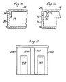
- FIG. 8 and 11 an alternative embodiment is shown wherein the like portions, namely the top 14 and the base 12 are utilized.
- the two respective portions employ a modified insert or tray.
- a tray 200 is shown having side walls 202, 204, 206 and 208.
- the two outer walls 202 and 208 are formed in the same manner as the side walls 42 and 44.
- a pair of interior walls 204 and 206 are formed in the same manner as the outer side walls. In this manner, rectangular magnetic cards can be inserted into the rectangular slots that are provided.
- a pair of tabs that form fan tabs similar to tabs 58 and 60 are provided. These tabs have been numbered 258 and 260 in respective correspondence to the showing of Figure 1. All the other details of the invention are substantially the same in all respects as the showing of Figure 1. This allows magnetic cards to be held within the rectangular pockets provided between the walls 202, 204, 206 and 208 behind the fan tabs 258 and 260, so that the entire series of magnetic cards can be implaced within the pockets and held thereby.
- this invention is a broad step over the prior art insofar as it provides storage for memory disks in an easy, facile and compact manner.
- the invention is to be read broadly in light of the following claims for covering the encapsulation, storage and containerization of magnetic memory disks or cards.
Landscapes
- Packaging For Recording Disks (AREA)
Applications Claiming Priority (2)
| Application Number | Priority Date | Filing Date | Title |
|---|---|---|---|
| US83448877A | 1977-09-19 | 1977-09-19 | |
| US834488 | 1977-09-19 |
Publications (2)
| Publication Number | Publication Date |
|---|---|
| EP0001353A1 true EP0001353A1 (de) | 1979-04-04 |
| EP0001353B1 EP0001353B1 (de) | 1981-12-09 |
Family
ID=25267053
Family Applications (1)
| Application Number | Title | Priority Date | Filing Date |
|---|---|---|---|
| EP78300402A Expired EP0001353B1 (de) | 1977-09-19 | 1978-09-19 | Behälter für magnetische Speicherelemente |
Country Status (3)
| Country | Link |
|---|---|
| EP (1) | EP0001353B1 (de) |
| DE (1) | DE2861436D1 (de) |
| IT (1) | IT1099087B (de) |
Cited By (8)
| Publication number | Priority date | Publication date | Assignee | Title |
|---|---|---|---|---|
| US4289235A (en) * | 1979-09-17 | 1981-09-15 | Egly Robert A | Magnetic cassette storage case |
| EP0109092A1 (de) * | 1982-11-16 | 1984-05-23 | Otto Burgschweiger | Aufnahmebehälter |
| FR2571169A1 (fr) * | 1984-10-01 | 1986-04-04 | Posso Sa | Boite pour le rangement, la presentation et la selection des disquettes ou autres supports magnetiques. |
| FR2577888A1 (fr) * | 1985-02-25 | 1986-08-29 | Achat Distr Article Classement | Boite de rangement |
| EP0293272A2 (de) * | 1987-05-28 | 1988-11-30 | ABACAD SYSTEMS & DESIGNS LTD. | Aufbewahrungsbehälter |
| WO1990002403A1 (de) * | 1988-08-29 | 1990-03-08 | Dunker Petra | Aufbewahrungskassette für kreisförmige informationsplatten |
| EP0417726A2 (de) * | 1989-09-12 | 1991-03-20 | Daicel Chemical Industries, Ltd. | Behälter fÀ¼r optische Platten |
| US5249177A (en) * | 1989-09-12 | 1993-09-28 | Daicel Chemical Industries Ltd. | Structure for preventing dislocation of a spring in an optical disk cartridge |
Citations (3)
| Publication number | Priority date | Publication date | Assignee | Title |
|---|---|---|---|---|
| CH367339A (fr) * | 1959-08-11 | 1963-02-15 | Bernard Franck Pierre Leon | Ensemble comprenant un portefeuille repliable renfermant des articles plats amovibles |
| DE7245400U (de) * | 1973-03-29 | Badische Anilin & Soda Fabrik Ag | Behälter für Magnetbandkassetten, insbesondere für Kompaktkassetten | |
| DE7624173U1 (de) * | 1976-07-31 | 1977-03-31 | Presch Klaus | Sammelkassette in Buchform fuer Bild-Platten |
-
1978
- 1978-09-15 IT IT27733/78A patent/IT1099087B/it active
- 1978-09-19 DE DE7878300402T patent/DE2861436D1/de not_active Expired
- 1978-09-19 EP EP78300402A patent/EP0001353B1/de not_active Expired
Patent Citations (3)
| Publication number | Priority date | Publication date | Assignee | Title |
|---|---|---|---|---|
| DE7245400U (de) * | 1973-03-29 | Badische Anilin & Soda Fabrik Ag | Behälter für Magnetbandkassetten, insbesondere für Kompaktkassetten | |
| CH367339A (fr) * | 1959-08-11 | 1963-02-15 | Bernard Franck Pierre Leon | Ensemble comprenant un portefeuille repliable renfermant des articles plats amovibles |
| DE7624173U1 (de) * | 1976-07-31 | 1977-03-31 | Presch Klaus | Sammelkassette in Buchform fuer Bild-Platten |
Cited By (15)
| Publication number | Priority date | Publication date | Assignee | Title |
|---|---|---|---|---|
| US4289235A (en) * | 1979-09-17 | 1981-09-15 | Egly Robert A | Magnetic cassette storage case |
| US4724957A (en) * | 1982-11-16 | 1988-02-16 | Otto Burgschweiger | Container |
| EP0109092A1 (de) * | 1982-11-16 | 1984-05-23 | Otto Burgschweiger | Aufnahmebehälter |
| WO1984002029A1 (en) * | 1982-11-16 | 1984-05-24 | Otto Burgschweiger | Container |
| FR2571169A1 (fr) * | 1984-10-01 | 1986-04-04 | Posso Sa | Boite pour le rangement, la presentation et la selection des disquettes ou autres supports magnetiques. |
| EP0177415A1 (de) * | 1984-10-01 | 1986-04-09 | Posso S.A. | Behälter zum Einordnen, Präsentieren und Auswählen von Platten und anderen magnetischen Trägern |
| US4986415A (en) * | 1984-10-01 | 1991-01-22 | Posso S.A. | Box for the storage, display and selection of diskettes or other magnetic members |
| FR2577888A1 (fr) * | 1985-02-25 | 1986-08-29 | Achat Distr Article Classement | Boite de rangement |
| EP0293272A2 (de) * | 1987-05-28 | 1988-11-30 | ABACAD SYSTEMS & DESIGNS LTD. | Aufbewahrungsbehälter |
| EP0293272A3 (de) * | 1987-05-28 | 1990-08-08 | ABACAD SYSTEMS & DESIGNS LTD. | Aufbewahrungsbehälter |
| WO1990002403A1 (de) * | 1988-08-29 | 1990-03-08 | Dunker Petra | Aufbewahrungskassette für kreisförmige informationsplatten |
| US5284248A (en) * | 1988-08-29 | 1994-02-08 | Cartonneries De Thulin, S.A. | Storage case and a disc holding part for storage cases for round data discs |
| EP0417726A2 (de) * | 1989-09-12 | 1991-03-20 | Daicel Chemical Industries, Ltd. | Behälter fÀ¼r optische Platten |
| EP0417726A3 (en) * | 1989-09-12 | 1992-07-01 | Daicel Chemical Industries, Ltd. | Optical disk cartridge |
| US5249177A (en) * | 1989-09-12 | 1993-09-28 | Daicel Chemical Industries Ltd. | Structure for preventing dislocation of a spring in an optical disk cartridge |
Also Published As
| Publication number | Publication date |
|---|---|
| EP0001353B1 (de) | 1981-12-09 |
| DE2861436D1 (en) | 1982-02-04 |
| IT1099087B (it) | 1985-09-18 |
| IT7827733A0 (it) | 1978-09-15 |
Similar Documents
| Publication | Publication Date | Title |
|---|---|---|
| US4225038A (en) | Magnetic disk storage case | |
| US5513749A (en) | Storage case for multiple compact discs | |
| US5377825A (en) | Compact disc storage case | |
| US4771890A (en) | Disk retainer and packaging system for optical disks | |
| US5188228A (en) | Compact disk holder | |
| US3866751A (en) | Book with cassette holding recess | |
| US4289235A (en) | Magnetic cassette storage case | |
| US4860897A (en) | Disc storage device | |
| US4330161A (en) | Storage unit for tape cassettes | |
| US4545486A (en) | Container and storage system for photographic prints and negatives | |
| US5477961A (en) | Storage container for digital media and associated materials | |
| US20060289318A1 (en) | Closable package for retaining multiple discs in pouch-type holders or disc-receiving trays | |
| EP0001353A1 (de) | Behälter für magnetische Speicherelemente | |
| EP0568298A1 (de) | Schachtel für Kompaktdisk, Minidisk, Kassette oder Kompaktkassette | |
| US4790434A (en) | Data cartridge storage and handling system | |
| US20050241970A1 (en) | Media disc storage device | |
| EP0186359A2 (de) | Behälter für Software | |
| US4009781A (en) | Slide tray and tape cassette container | |
| EP0050485A1 (de) | Einteiliger Behälter mit Klappdeckel | |
| US7156232B1 (en) | Hanging file system for CDs and DVDs | |
| GB2276609A (en) | Storage container for a compact disc | |
| JPH06191584A (ja) | 収納ケース | |
| GB2162826A (en) | Case for magnetic recording medium | |
| US5715970A (en) | Compact disk storage case apparatus | |
| WO1988006794A1 (en) | Arrangement for the storage of recording media |
Legal Events
| Date | Code | Title | Description |
|---|---|---|---|
| PUAI | Public reference made under article 153(3) epc to a published international application that has entered the european phase |
Free format text: ORIGINAL CODE: 0009012 |
|
| AK | Designated contracting states |
Designated state(s): BE CH DE FR GB NL |
|
| 17P | Request for examination filed | ||
| GRAA | (expected) grant |
Free format text: ORIGINAL CODE: 0009210 |
|
| AK | Designated contracting states |
Designated state(s): BE CH DE FR GB NL |
|
| REF | Corresponds to: |
Ref document number: 2861436 Country of ref document: DE Date of ref document: 19820204 |
|
| PGFP | Annual fee paid to national office [announced via postgrant information from national office to epo] |
Ref country code: NL Payment date: 19860930 Year of fee payment: 9 |
|
| PG25 | Lapsed in a contracting state [announced via postgrant information from national office to epo] |
Ref country code: NL Effective date: 19880401 |
|
| NLV4 | Nl: lapsed or anulled due to non-payment of the annual fee | ||
| PGFP | Annual fee paid to national office [announced via postgrant information from national office to epo] |
Ref country code: FR Payment date: 19890911 Year of fee payment: 12 |
|
| PGFP | Annual fee paid to national office [announced via postgrant information from national office to epo] |
Ref country code: CH Payment date: 19890927 Year of fee payment: 12 |
|
| PGFP | Annual fee paid to national office [announced via postgrant information from national office to epo] |
Ref country code: BE Payment date: 19890929 Year of fee payment: 12 |
|
| PGFP | Annual fee paid to national office [announced via postgrant information from national office to epo] |
Ref country code: DE Payment date: 19891031 Year of fee payment: 12 |
|
| PGFP | Annual fee paid to national office [announced via postgrant information from national office to epo] |
Ref country code: GB Payment date: 19900831 Year of fee payment: 13 |
|
| PG25 | Lapsed in a contracting state [announced via postgrant information from national office to epo] |
Ref country code: CH Effective date: 19900930 Ref country code: BE Effective date: 19900930 |
|
| BERE | Be: lapsed |
Owner name: EGLY ROBERT A. Effective date: 19900930 |
|
| PG25 | Lapsed in a contracting state [announced via postgrant information from national office to epo] |
Ref country code: FR Effective date: 19910530 |
|
| REG | Reference to a national code |
Ref country code: CH Ref legal event code: PL |
|
| PG25 | Lapsed in a contracting state [announced via postgrant information from national office to epo] |
Ref country code: DE Effective date: 19910601 |
|
| REG | Reference to a national code |
Ref country code: FR Ref legal event code: ST |
|
| PG25 | Lapsed in a contracting state [announced via postgrant information from national office to epo] |
Ref country code: GB Effective date: 19910919 |
|
| GBPC | Gb: european patent ceased through non-payment of renewal fee | ||
| PLBE | No opposition filed within time limit |
Free format text: ORIGINAL CODE: 0009261 |
|
| STAA | Information on the status of an ep patent application or granted ep patent |
Free format text: STATUS: NO OPPOSITION FILED WITHIN TIME LIMIT |