EP0001338B1 - Apparatus for determining the result of answers to a set of related questions - Google Patents
Apparatus for determining the result of answers to a set of related questions Download PDFInfo
- Publication number
- EP0001338B1 EP0001338B1 EP78300369A EP78300369A EP0001338B1 EP 0001338 B1 EP0001338 B1 EP 0001338B1 EP 78300369 A EP78300369 A EP 78300369A EP 78300369 A EP78300369 A EP 78300369A EP 0001338 B1 EP0001338 B1 EP 0001338B1
- Authority
- EP
- European Patent Office
- Prior art keywords
- answer
- symbols
- answers
- array
- question
- Prior art date
- Legal status (The legal status is an assumption and is not a legal conclusion. Google has not performed a legal analysis and makes no representation as to the accuracy of the status listed.)
- Expired
Links
Images


Classifications
-
- G—PHYSICS
- G06—COMPUTING OR CALCULATING; COUNTING
- G06K—GRAPHICAL DATA READING; PRESENTATION OF DATA; RECORD CARRIERS; HANDLING RECORD CARRIERS
- G06K19/00—Record carriers for use with machines and with at least a part designed to carry digital markings
- G06K19/04—Record carriers for use with machines and with at least a part designed to carry digital markings characterised by the shape
-
- G—PHYSICS
- G09—EDUCATION; CRYPTOGRAPHY; DISPLAY; ADVERTISING; SEALS
- G09B—EDUCATIONAL OR DEMONSTRATION APPLIANCES; APPLIANCES FOR TEACHING, OR COMMUNICATING WITH, THE BLIND, DEAF OR MUTE; MODELS; PLANETARIA; GLOBES; MAPS; DIAGRAMS
- G09B3/00—Manually or mechanically operated teaching appliances working with questions and answers
- G09B3/06—Manually or mechanically operated teaching appliances working with questions and answers of the multiple-choice answer type, i.e. where a given question is provided with a series of answers and a choice has to be made
- G09B3/08—Manually or mechanically operated teaching appliances working with questions and answers of the multiple-choice answer type, i.e. where a given question is provided with a series of answers and a choice has to be made of chart form
- G09B3/085—Manually or mechanically operated teaching appliances working with questions and answers of the multiple-choice answer type, i.e. where a given question is provided with a series of answers and a choice has to be made of chart form with invisibly printed correct answer; the answer being rendered visible by special optical means, e.g. filters; mirrors
Definitions
- the invention relates to apparatus for determining the result of answers to a set of related questions each having at least two answers, comprising, for every question, an answer device which is operable to present, in accordance with answers selected by the operator, answer symbols, forming part of an array, the presented answer symbol or symbols associated with each question being disposed in a line of the said part of the array, all the presented symbols defining not more than one complete path through the said part of the array which leads the operator to a single reference out of a set of references carried by a record member.
- question as used in this description is intended to include any statement, which may be a statement in symbolic form, to which there are a plurality of responses.
- answer is intended to include any such response for example, true, false ; yes, no ; less than, equal to, greater than.
- a person wishing to use the decision table to assist him in choosing the action to be taken in a situation must first describe the situation by a set of answers to the questions of the decision table. He must then search through the array of answers to find the column which corresponds to that set and hence the associated instruction.
- the answer symbols may be in the form of apertures in cards, the alignment of an aperture in each of the cards allowing the operator to see a reference on a record member at the bottom of the stack.
- the answer symbols may be in the form of apertures in cards, the alignment of an aperture in each of the cards allowing the operator to see a reference on a record member at the bottom of the stack.
- this requires accuracy of manufacture and care in use to ensure that the reference is visible.
- it is difficult for the operator to find the aperture through which a reference is visible and as the number of cards in the stack increases it becomes progressively more difficult to ensure that the apertures are aligned, to find the right aperture, and to see the reference which is only illuminated through the stacked apertures.
- the answer symbols are marks on transparent sheets but again the problem of finding a path consisting of several superimposed marks becomes progressively more difficult as the number of answer devices increases, both because of the loss of light recurring in the stacked transparent sheets and because of the difficulty of determining whether all the symbols are present in a pattern resulting from superimposition.
- the answer devices are constructed to present an essentially two dimensional display to the operator, who can thus see a path leading across the display to the reference and made up of a succession of answer symbols from a series of answer devices. Additional answer devices can be added as required and simply extend the length of the path leading to the reference. The greater the number of answer devices the more clearly the single complete path will stand out from all the broken and incomplete paths formed by other answer symbols.
- Apparatus as defined in the preamble is characterised, in accordance with the invention, in that the lines of presented answer symbols are disposed side-by-side and the set of references is arranged adjacent the lines of answer symbols whereby the operator can scan all the presented answer symbols when searching for the said complete path which extends across the lines of answer symbols to the said single reference.
- An advantage of the invention is that it can provide a check on the accuracy and completeness of an array by always presenting, after operation of all the answer devices, one, and only one, complete path when the apparatus used is based on an array in which all possible combinations of answers to a set of questions are represented.
- the absence of a complete path through the array, or the presence of more than one complete path, indicates that the array on which the design of the apparatus is based is incomplete or incorrect.
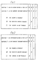
- Figs. 1 and 2 show decision tables relating to a simple problem in tax law. To decide whether income is taxable two questions must be answered - Has the income arisen in the U.K. ? Is the tax-payer resident in the U.K. ? Each question has only two possible answers - Yes and No. In Fig. 1, adjacent the questions is shown an array of answer symbols in which the columns represent the four possible combinations of answers to the two questions, NN, NY etc. representing No No, No Yes etc. Associated with each combination of answers is a statement of the correct action to be taken in the situation described by that combination of answers, for example if the answers to both questions is No then the income is not taxable.
- the decision table of Fig. 1 can be abridged to that of Fig. 2.
- the dash in the third column against the second question indicates that the answer to the second question, when combined with the answer Yes to the first question, does not affect the action to be taken.
- a complete array of answer symbols is recorded on a record member adjacent a column of questions which may be written out in full or merely identified by numbers.
- Below each column of the array there is a cross in line with a reference to the correct action to be taken.
- the crosses and references are recorded on the record member which is preferably a sheet of paper or cardboard.
- the symbols Y representing Yes answers are recorded in a different colour to the symbols N representing No answers, for example the Ys are in green and the Ns are in red.
- the dash indicating that both answers Yes and No lead to the same reference is recorded in black as are the crosses, references, and the questions or the numbers which identify the questions.
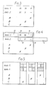
- Each answer device comprises two portions of transparent colour filter material joined together to form a strip 10.
- One portion, the right-hand half 11, of each strip 10 is green filter material and one portion, the left-hand half 12, is red, these colours being chosen to correspond to the colours used for the answer symbols.
- Each portion of colour filter material is large enough to cover a complete line of the array of answer symbols on the record member, the line being that associated with one of the questions.
- each strip is positioned either with the green portion 11 covering the line of the array or with the red portion 12 covering the line of the array, these positions of the strip corresponding to selection of No or Yes answers respectively.
- Fig. 4 shows the apparatus in use.
- the operator has selected the answer No to question one and the answer Yes to question two.
- the strips of the answer devices have been positioned accordingly, the line of the array associated with question one being covered by the green portion of the first strip and the line associated with question two being covered by the red portion of the second strip. Consequently, only the red N symbols in the line associated with question one, i.e. the symbols corresponding to the selected answer, are clearly visible, the green Y symbol being virtually indistinguishable from the background when viewed through the portion of green filter material.
- the Y symbol is shown in broken lines in Fig. 4.
- the green Y symbol is clearly visible through the portion of red filter material and the red N is not.
- the black dash is clearly visible through the red filter material and it would also be visible through the green filter material.
- each answer device when operated, renders some answer symbols in a line of the array clearly visible and obscures the remainder of the symbols in that line. Consequently only part of the array is rendered clearly visible.
- the answer symbols rendered clearly visible are those corresponding to the selected answer.
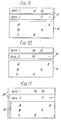
- Figs. 5, 6 and 7 show a similar device to that shown in Figs. 3 and 4. However, instead of using the letters N and Y to represent No and Yes answers, a black square is used in the left-hand half or right-hand half respectively of a column of the array.
- Fig. 5 shows a record member on which is recorded the array shown in Fig. 2 together with references to actions to be taken.
- Fig. 6 shows the answer devices each of which comprises a strip 13 of black paper or cardboard having windows 14 cut out. Each strip 13 has as many windows 14 as there are columns in the array, each window being the same size as the black squares recorded on the record member.
- Fig. 5 shows a record member on which is recorded the array shown in Fig. 2 together with references to actions to be taken.
- Fig. 6 shows the answer devices each of which comprises a strip 13 of black paper or cardboard having windows 14 cut out. Each strip 13 has as many windows 14 as there are columns in the array, each window being the same size as the black squares recorded on the record
- each strip is arranged in front of the record member in line with a question and, in use, is positioned with the windows 14 either over the left-hand halves of the columns of the array or over the right-hand halves.
- the strip in line with question one is positioned with its windows 14 over the left-hand halves of the columns of the array and this position corresponds to the selection of the answer No.
- the strip in line with question two is positioned with its windows over the right-hand halves of the columns of the array and this corresponds to selection of the answer Yes for question two.
- Fig. 7 shows the device in use after operation of the answer devices in accordance with selection of No and Yes answers to questions one and two respectively.
- the central column is the unbroken black column. The situation shown in Fig. 7 corresponds to that shown for a different device in Fig. 4.
- Fig. 8 shows a record member which can be substituted for the record member shown in Fig. 3 and used with the device shown in Fig. 4.
- the array of Fig. 2 is recorded on the record member of Fig. 8 as a network of paths commonly called a decision tree. Yes and No answers are represented by different coloured segments of paths, for example green and red segments respectively.
- an unbroken line in Fig. 8 represents a green line on the record member
- a broken line represents a red line on the record member
- a double line represents a black line on the record member.
- a black line on the record member indicates that both answers Yes and No give the same result.
- the record member of Fig. 8 is for use with answer devices with comprise strips of material each having a portion of green colour filter material and a portion of red colour filter material.
- the record member can thus replace the record member of Fig. 3 in the device of Fig. 4.
- the answer devices are operated in accordance with answers selected by the operator. After all the answer devices have been operated some segments of paths are clearly visible whilst the remainder are obscured and there is only one complete path which is clearly visible. The operator follows this path and so locates the reference to the action to be taken.
- the paths can be made easier to follow if black dots are recorded on the record member where each segment of a path branches into further segments. It is also advantageous to mark with a dot the black lines which indicate that either answer gives the same result. If this is done the operator can tell which segments of the path will be unaffected by a change in answer without having to operate the answer device concerned.
- the answer devices are movable strips which are positioned in accordance with selected answers to render part of an array of answer symbols clearly visible.
- the arrays shown in Figs. 3, 5 and 8 can be recorded on a sheet of transparent material to produce record members which are suitable for illumination from behind the member using coloured light.
- Each answer device thus comprises means to evenly illuminate with light of different colours a line of the array associated with one question.
- each answer device would have to provide red and green light.
- a single light source could be used in combination with filters or there could be two independent light sources.
- the record member can be very small, for example it can be a portion of microfilm, and illuminated by means of fibre optic light guides.
- each answer device can comprise strips of coloured material placed behind a line of the array of answer symbols.
- a transparent record member bearing answer symbols in different colours can be mounted in a projector in order to project the answer symbols on a screen which includes strips of coloured material.
- coloured strips can be produced on a white screen by incorporating strips of colour filter material in a projector and projecting light of different colours on the screen.
- FIGs. 9 and 10 Another type of answer device is shown in Figs. 9 and 10.
- the array of answer symbols is not recorded on a record member but is recorded on the strips of material 15 which are the answer devices.
- a record member 16 carries references to actions to be taken and, in line with the references, crosses to assist in locating the references.
- Each answer device comprises a strip of material 15, such as paper or cardboard, on which are recorded the answer symbols from one line of the array of symbols shown in Fig. 2.
- the answer symbols are not all recorded on one side of the strip but are divided into Yes symbols and No symbols which are recorded on opposite sides of the strip.
- the dash which indicates that both answers give the same result is recorded on both sides of a strip.
- the symbols on one side of a strip have the same relative positions as the corresponding symbols in the array of Fig. 2.
- Fig. 11 shows apparatus similar to that shown in Figs. 9 and 10.
- the apparatus comprises two answer devices 24 and a record member 25, which is identical to the record member 16 shown in Figs. 9 and 10.
- Each answer device 24 is a sheet of material, for example paper, which extends behind the record member and which has a question and answer symbol corresponding to one answer to the question recorded on one side of the sheet along the upper edge.
- the sheets are of different sizes and are arranged behind the record member such that when the lower edges of the sheets are level with the lower edge of the record member, the symbols recorded along the upper edges of the sheets are visible.
- Each answer device 24 has the answer symbols corresponding to the different answers to a question recorded along the upper edge of opposite sides of the sheet in a similar manner to that in which symbols are recorded on the strips 15 shown in Figs. 9 and 10.
- the operator selects an answer to each question, positions the sheets such that the answer symbols corresponding to the selected answers are visible and scans the visible symbols for a complete column of symbols.
- Fig. 11 shows the situation when the answer devices 24 have been operated in accordance with the answers No and Y to questions one and two respectively and so corresponds to Fig. 9.
- each answer device has four portions in which answer symbols can be recorded, i.e. along the upper and lower edges on both sides of the sheet.
- Such answer devices can be used with questions each having as many as four answers, for example, with questions having four different answers, each of the said. four portions of a sheet bears answer symbols corresponding to one of the four possible answers to a question.
- Fig. 12 In Fig. 12 is shown apparatus which is very similar to that shown in Figs. 9 and 10 except that the Yes and No symbols are recorded in different portions of one side of a strip of material 17 instead of on opposite sides.
- the situation shown in Fig. 12 is equivalent to that shown in Fig. 9.
- the symbols Y and N could be replaced by vertical strokes because the operator has merely to search for a complete column of symbols. He does not need to be able to distinguish between the Yes and No symbols providing he knows, from the position of an answer strip 17, whether the strip has been positioned in accordance with a Yes answer or a No answer. If the Y and N symbols in the apparatus of Fig. 12 were replaced by embossed vertical strokes, the apparatus could be used by a blind operator. In such an apparatus answer symbols would be presented by operation of the answer devices, without necessarily being clearly visible.
- Fig. 13 is a section through an answer device suitable for use with the record member of Fig. 3 or 8.
- the answer device comprises an endless belt 18 having a portion 19 of green colour filter material and a portion 20 of red colour filter material, the two filter portions being separated by two transparent portions 21.
- a handle 22 is fixed to the belt to enable the operator to move the belt around the tensioning rollers 23 and so position the red portion 20 or the green portion 19 over a line of the array recorded on a record member.
- Any of the answer devices described which comprise strips of material can be adapted to use a belt similar to that shown in Fig. 13.
- the apparatus is based on the decision table of Fig. 2, which is a complete decision table in the sense that all possible combinations of answers to the two questions are represented.
- the presented answer symbols will always define one and only one path through the presented part of the array. This feature can be used as a check on the completeness of the decision table on which the apparatus is based.
- the presented answer symbols will not define a path through the presented part of the array when the answer devices have been operated in accordance with a combination of answers which is of no interest to the operator.
- the questions need not have only two possible answers and use of the apparatus shown in Fig. 11 with questions having more than two answers has been described.
- the apparatus shown in Fig. 12 can easily be adapted for use with questions having more than two answers by making each strip longer and recording the symbols corresponding to the different answers to any one question in different portions of one side of the strip.
- Apparatus having answer symbols recorded in different colours on a record member can be adapted for use with questions having three answers.
- the three different answer symbols are recorded in the secondary colours magenta, yellow and cyan. Covering the array with a colour filter of a primary colour, green, blue or red, would obscure symbols recorded in two of the secondary colours whilst rendering the symbols recorded in the third secondary colour clearly visible.
- the apparatus can be adapted for use in projectors or microfilm readers.
- the answer devices can comprise means to project coloured light on an opaque record member which carries an array of answer symbols of different colours together with references.
- any suitable means can be provided for guiding or supporting the strips in the correct position relative to the record member, for example in the apparatus shown in Fig. 4 embossed lines can be provided on the record member and the strips can slide between the lines.
- a sheet of transparent material can be fixed to the embossed lines thus forming closed channels in which the strips can slide. Magnets can be used to facilitate movement of the strips within the channels.
- the answer devices can be mounted in a frame in order to enable movement of the answer devices as one unit relative to the record member as the operator scans for a complete path through the presented part of the array.
- the portions of colour filter materials need not be large enough to cover a line of the array if the answer devices can be moved as one unit across the record member as the operator looks for a complete path.
- the portions of the array which are to be presented after operation of the answer devices could be generated electronically and displayed on a television screen together with references.
- the screen becomes a record member for the duration of display of the array and references.
- Apparatus in which colour filters are used to differentiate between symbols recorded in different colours can be adapted to use diffraction gratings or materials which polarise light if the symbols are recorded on the record member as portions of compatible diffraction gratings or polarising materials.
Landscapes
- Engineering & Computer Science (AREA)
- Physics & Mathematics (AREA)
- General Physics & Mathematics (AREA)
- Theoretical Computer Science (AREA)
- Business, Economics & Management (AREA)
- Educational Administration (AREA)
- Educational Technology (AREA)
- Toys (AREA)
- Collation Of Sheets And Webs (AREA)
- Electrically Operated Instructional Devices (AREA)
Applications Claiming Priority (2)
| Application Number | Priority Date | Filing Date | Title |
|---|---|---|---|
| GB38926/77A GB1598787A (en) | 1977-09-19 | 1977-09-19 | Apparatus for determining the result of answers to a set of related questions |
| GB3892677 | 1978-05-26 |
Publications (2)
| Publication Number | Publication Date |
|---|---|
| EP0001338A1 EP0001338A1 (en) | 1979-04-04 |
| EP0001338B1 true EP0001338B1 (en) | 1981-04-15 |
Family
ID=10406529
Family Applications (1)
| Application Number | Title | Priority Date | Filing Date |
|---|---|---|---|
| EP78300369A Expired EP0001338B1 (en) | 1977-09-19 | 1978-09-11 | Apparatus for determining the result of answers to a set of related questions |
Country Status (6)
| Country | Link |
|---|---|
| US (1) | US4213251A (cg-RX-API-DMAC7.html) |
| EP (1) | EP0001338B1 (cg-RX-API-DMAC7.html) |
| JP (1) | JPS5472124A (cg-RX-API-DMAC7.html) |
| AU (1) | AU518602B2 (cg-RX-API-DMAC7.html) |
| CA (1) | CA1094315A (cg-RX-API-DMAC7.html) |
| GB (1) | GB1598787A (cg-RX-API-DMAC7.html) |
Families Citing this family (48)
| Publication number | Priority date | Publication date | Assignee | Title |
|---|---|---|---|---|
| FR2577056A1 (fr) * | 1985-02-06 | 1986-08-08 | Roche Olivier | Dispositif pour lire et comparer des grilles de 5 fois 10 cases, dont certaines ont ete cochees, avec une grille type, programmable |
| US6315572B1 (en) * | 1995-03-22 | 2001-11-13 | William M. Bancroft | Method and system for computerized authoring, learning, and evaluation |
| US20020042041A1 (en) * | 1995-03-22 | 2002-04-11 | Owens Terry S. | Systems and methods for organizing data relationships |
| US5749736A (en) * | 1995-03-22 | 1998-05-12 | Taras Development | Method and system for computerized learning, response, and evaluation |
| US6701322B1 (en) * | 2000-06-07 | 2004-03-02 | Ge Financial Assurance Holdings, Inc. | Interactive customer-business interview system and process for managing interview flow |
| GB0208613D0 (en) * | 2002-04-15 | 2002-05-22 | Rickard Basil | Control structure |
| EP2030669B1 (de) * | 2007-08-16 | 2014-04-02 | Sulzer Metco AG | Verfahren zum Herstellen einer wasserstoffpermeablen Membran sowie wasserstoffpermeable Membran |
| US20090142742A1 (en) * | 2007-11-29 | 2009-06-04 | Adele Goldberg | Analysis for Assessing Test Taker Responses to Puzzle-Like Questions |
| US9760953B1 (en) | 2014-03-12 | 2017-09-12 | Intuit Inc. | Computer implemented methods systems and articles of manufacture for identifying tax return preparation application questions based on semantic dependency |
| US10387969B1 (en) | 2014-03-12 | 2019-08-20 | Intuit Inc. | Computer implemented methods systems and articles of manufacture for suggestion-based interview engine for tax return preparation application |
| US10915970B1 (en) | 2014-03-12 | 2021-02-09 | Intuit Inc. | Computer implemented methods systems and articles of manufacture for communicating and resolving electronic tax return errors and inconsistent data |
| US9916628B1 (en) | 2014-07-31 | 2018-03-13 | Intuit Inc. | Interview question modification during preparation of electronic tax return |
| US11430072B1 (en) | 2014-07-31 | 2022-08-30 | Intuit Inc. | System and method of generating estimates used to calculate taxes |
| US10867355B1 (en) | 2014-07-31 | 2020-12-15 | Intuit Inc. | Computer implemented methods systems and articles of manufacture for preparing electronic tax return with assumption data |
| US11861734B1 (en) | 2014-08-18 | 2024-01-02 | Intuit Inc. | Methods systems and articles of manufacture for efficiently calculating a tax return in a tax return preparation application |
| US10977743B1 (en) | 2014-08-18 | 2021-04-13 | Intuit Inc. | Computer implemented methods systems and articles of manufacture for instance and suggestion differentiation during preparation of electronic tax return |
| US10970793B1 (en) | 2014-08-18 | 2021-04-06 | Intuit Inc. | Methods systems and articles of manufacture for tailoring a user experience in preparing an electronic tax return |
| US10540725B1 (en) | 2014-08-18 | 2020-01-21 | Intuit Inc. | Methods systems and articles of manufacture for handling non-standard screen changes in preparing an electronic tax return |
| US9922376B1 (en) | 2014-10-31 | 2018-03-20 | Intuit Inc. | Systems and methods for determining impact chains from a tax calculation graph of a tax preparation system |
| US10169826B1 (en) | 2014-10-31 | 2019-01-01 | Intuit Inc. | System and method for generating explanations for tax calculations |
| US10796381B1 (en) | 2014-10-31 | 2020-10-06 | Intuit Inc. | Systems and methods for determining impact correlations from a tax calculation graph of a tax preparation system |
| US10387970B1 (en) | 2014-11-25 | 2019-08-20 | Intuit Inc. | Systems and methods for analyzing and generating explanations for changes in tax return results |
| US10296984B1 (en) | 2014-11-26 | 2019-05-21 | Intuit Inc. | Systems, methods and articles of manufacture for determining relevancy of tax topics in a tax preparation system |
| US11222384B1 (en) | 2014-11-26 | 2022-01-11 | Intuit Inc. | System and method for automated data estimation for tax preparation |
| US10235721B1 (en) | 2014-11-26 | 2019-03-19 | Intuit Inc. | System and method for automated data gathering for tax preparation |
| US10235722B1 (en) | 2014-11-26 | 2019-03-19 | Intuit Inc. | Systems and methods for analyzing and determining estimated taxes |
| US10157426B1 (en) | 2014-11-28 | 2018-12-18 | Intuit Inc. | Dynamic pagination of tax return questions during preparation of electronic tax return |
| US10572952B1 (en) | 2014-12-01 | 2020-02-25 | Intuit Inc. | Computer implemented methods systems and articles of manufacture for cross-field validation during preparation of electronic tax return |
| US10140666B1 (en) | 2015-03-30 | 2018-11-27 | Intuit Inc. | System and method for targeted data gathering for tax preparation |
| US10796382B1 (en) | 2015-03-30 | 2020-10-06 | Intuit Inc. | Computer-implemented method for generating a customized tax preparation experience |
| US10872384B1 (en) | 2015-03-30 | 2020-12-22 | Intuit Inc. | System and method for generating explanations for year-over-year tax changes |
| US9990678B1 (en) | 2015-03-31 | 2018-06-05 | Intuit Inc. | Systems methods and articles of manufacture for assessing trustworthiness of electronic tax return data |
| US11113771B1 (en) * | 2015-04-28 | 2021-09-07 | Intuit Inc. | Systems, methods and articles for generating sub-graphs of a tax calculation graph of a tax preparation system |
| US10685407B1 (en) | 2015-04-30 | 2020-06-16 | Intuit Inc. | Computer-implemented methods, systems and articles of manufacture for tax topic prediction utilizing prior tax returns |
| US10664924B1 (en) | 2015-04-30 | 2020-05-26 | Intuit Inc. | Computer-implemented methods, systems and articles of manufacture for processing sensitive electronic tax return data |
| US10664925B2 (en) | 2015-06-30 | 2020-05-26 | Intuit Inc. | Systems, methods and articles for determining tax recommendations |
| US10402913B2 (en) | 2015-07-30 | 2019-09-03 | Intuit Inc. | Generation of personalized and hybrid responses to queries submitted from within tax return preparation system during preparation of electronic tax return |
| US10607298B1 (en) | 2015-07-30 | 2020-03-31 | Intuit Inc. | System and method for indicating sections of electronic tax forms for which narrative explanations can be presented |
| US11176620B1 (en) * | 2016-06-28 | 2021-11-16 | Intuit Inc. | Systems and methods for generating an error report listing errors in the preparation of a payroll tax form |
| US10796231B2 (en) | 2016-07-26 | 2020-10-06 | Intuit Inc. | Computer-implemented systems and methods for preparing compliance forms to meet regulatory requirements |
| US10769592B1 (en) | 2016-07-27 | 2020-09-08 | Intuit Inc. | Methods, systems and computer program products for generating explanations for a benefit qualification change |
| US11087411B2 (en) | 2016-07-27 | 2021-08-10 | Intuit Inc. | Computerized tax return preparation system and computer generated user interfaces for tax topic completion status modifications |
| US11055794B1 (en) | 2016-07-27 | 2021-07-06 | Intuit Inc. | Methods, systems and computer program products for estimating likelihood of qualifying for benefit |
| US10872315B1 (en) | 2016-07-27 | 2020-12-22 | Intuit Inc. | Methods, systems and computer program products for prioritization of benefit qualification questions |
| US10762472B1 (en) | 2016-07-27 | 2020-09-01 | Intuit Inc. | Methods, systems and computer program products for generating notifications of benefit qualification change |
| US10664926B2 (en) | 2016-10-26 | 2020-05-26 | Intuit Inc. | Methods, systems and computer program products for generating and presenting explanations for tax questions |
| US12020334B2 (en) | 2016-10-26 | 2024-06-25 | Intuit Inc. | Methods, systems and computer program products for generating and presenting explanations for tax questions |
| US11138676B2 (en) | 2016-11-29 | 2021-10-05 | Intuit Inc. | Methods, systems and computer program products for collecting tax data |
Family Cites Families (5)
| Publication number | Priority date | Publication date | Assignee | Title |
|---|---|---|---|---|
| US2984018A (en) * | 1955-03-23 | 1961-05-16 | Jr Charles G Coleman | Methods and means for solving problems by progressive analysis |
| US2948969A (en) * | 1955-03-23 | 1960-08-16 | Jr Charles G Coleman | Methods and means for solving problems by progressive analysis |
| US3251141A (en) * | 1962-04-23 | 1966-05-17 | Accelerated Instruction Method | Self-teaching educational device |
| US3478440A (en) * | 1966-09-26 | 1969-11-18 | Ralph W Ritchie | Teaching device |
| US3541702A (en) * | 1968-11-25 | 1970-11-24 | Julius G Cohen | Educational device |
-
1977
- 1977-09-19 GB GB38926/77A patent/GB1598787A/en not_active Expired
-
1978
- 1978-09-07 US US05/940,312 patent/US4213251A/en not_active Expired - Lifetime
- 1978-09-08 JP JP10985578A patent/JPS5472124A/ja active Granted
- 1978-09-11 EP EP78300369A patent/EP0001338B1/en not_active Expired
- 1978-09-18 CA CA311,516A patent/CA1094315A/en not_active Expired
- 1978-09-18 AU AU39935/78A patent/AU518602B2/en not_active Expired
Also Published As
| Publication number | Publication date |
|---|---|
| JPS5472124A (en) | 1979-06-09 |
| AU3993578A (en) | 1980-03-27 |
| EP0001338A1 (en) | 1979-04-04 |
| AU518602B2 (en) | 1981-10-08 |
| CA1094315A (en) | 1981-01-27 |
| JPS6129510B2 (cg-RX-API-DMAC7.html) | 1986-07-07 |
| US4213251A (en) | 1980-07-22 |
| GB1598787A (en) | 1981-09-23 |
Similar Documents
| Publication | Publication Date | Title |
|---|---|---|
| EP0001338B1 (en) | Apparatus for determining the result of answers to a set of related questions | |
| DE69213293T2 (de) | Tastatur mit beleuchteten Tasten | |
| US3419973A (en) | Mathematical teaching wheel | |
| EP0513375A1 (en) | Method for recording data, and printed body printed by the method, and data recording medium, and method for reading data from data recording the medium | |
| US4106846A (en) | Television color bar matching device | |
| DE69708012T2 (de) | Bildwahlvorrichtung für photographisches Kopiergerät | |
| US2137447A (en) | Educational device | |
| US2390439A (en) | Optical record interpreter | |
| US1958192A (en) | Color match guide | |
| US3579864A (en) | Teaching device | |
| DE3820804C2 (cg-RX-API-DMAC7.html) | ||
| US4192085A (en) | Teaching aid device for teaching the basic principles of arithmetic | |
| US2701423A (en) | Educational device with interfittable problem and answer members | |
| US2859541A (en) | Question and answer sheet with answers on both faces readable through translucent area | |
| US5192209A (en) | Color demonstrator | |
| US3413735A (en) | Optical pattern recognition system | |
| US472057A (en) | kalisce | |
| US4521091A (en) | Slide production system | |
| US3418728A (en) | Punch card interpreter | |
| US20100203485A1 (en) | Method for teaching multiplication and factorization | |
| DE2236132A1 (de) | Verfahren und einrichtung zur wissenspruefung | |
| US4094584A (en) | Format for color diffractive subtractive filters | |
| US3850072A (en) | Improvements in or relating to instructional apparatus for use in learning the construction of musical chords | |
| US3069788A (en) | Device for color demonstration | |
| US2911742A (en) | Educational appliance |
Legal Events
| Date | Code | Title | Description |
|---|---|---|---|
| PUAI | Public reference made under article 153(3) epc to a published international application that has entered the european phase |
Free format text: ORIGINAL CODE: 0009012 |
|
| AK | Designated contracting states |
Designated state(s): DE FR GB NL |
|
| 17P | Request for examination filed | ||
| GRAA | (expected) grant |
Free format text: ORIGINAL CODE: 0009210 |
|
| AK | Designated contracting states |
Designated state(s): DE FR GB NL |
|
| REF | Corresponds to: |
Ref document number: 2860621 Country of ref document: DE Date of ref document: 19810507 |
|
| PGFP | Annual fee paid to national office [announced via postgrant information from national office to epo] |
Ref country code: FR Payment date: 19840828 Year of fee payment: 7 |
|
| PGFP | Annual fee paid to national office [announced via postgrant information from national office to epo] |
Ref country code: DE Payment date: 19841129 Year of fee payment: 7 |
|
| PGFP | Annual fee paid to national office [announced via postgrant information from national office to epo] |
Ref country code: NL Payment date: 19860930 Year of fee payment: 9 |
|
| GBPC | Gb: european patent ceased through non-payment of renewal fee | ||
| PG25 | Lapsed in a contracting state [announced via postgrant information from national office to epo] |
Ref country code: NL Effective date: 19880401 |
|
| NLV4 | Nl: lapsed or anulled due to non-payment of the annual fee | ||
| PG25 | Lapsed in a contracting state [announced via postgrant information from national office to epo] |
Ref country code: FR Free format text: LAPSE BECAUSE OF NON-PAYMENT OF DUE FEES Effective date: 19880531 |
|
| PG25 | Lapsed in a contracting state [announced via postgrant information from national office to epo] |
Ref country code: DE Effective date: 19880601 |
|
| REG | Reference to a national code |
Ref country code: FR Ref legal event code: ST |
|
| PG25 | Lapsed in a contracting state [announced via postgrant information from national office to epo] |
Ref country code: GB Effective date: 19881117 |
|
| PLBE | No opposition filed within time limit |
Free format text: ORIGINAL CODE: 0009261 |
|
| STAA | Information on the status of an ep patent application or granted ep patent |
Free format text: STATUS: NO OPPOSITION FILED WITHIN TIME LIMIT |