EP0000827A1 - Apparatus for the production of mixtures, dispersions and the like - Google Patents
Apparatus for the production of mixtures, dispersions and the like Download PDFInfo
- Publication number
- EP0000827A1 EP0000827A1 EP7878300230A EP78300230A EP0000827A1 EP 0000827 A1 EP0000827 A1 EP 0000827A1 EP 7878300230 A EP7878300230 A EP 7878300230A EP 78300230 A EP78300230 A EP 78300230A EP 0000827 A1 EP0000827 A1 EP 0000827A1
- Authority
- EP
- European Patent Office
- Prior art keywords
- agitator
- vessel
- noise level
- contents
- level
- Prior art date
- Legal status (The legal status is an assumption and is not a legal conclusion. Google has not performed a legal analysis and makes no representation as to the accuracy of the status listed.)
- Granted
Links
Images
Classifications
-
- B—PERFORMING OPERATIONS; TRANSPORTING
- B01—PHYSICAL OR CHEMICAL PROCESSES OR APPARATUS IN GENERAL
- B01F—MIXING, e.g. DISSOLVING, EMULSIFYING OR DISPERSING
- B01F27/00—Mixers with rotary stirring devices in fixed receptacles; Kneaders
- B01F27/80—Mixers with rotary stirring devices in fixed receptacles; Kneaders with stirrers rotating about a substantially vertical axis
- B01F27/805—Mixers with rotary stirring devices in fixed receptacles; Kneaders with stirrers rotating about a substantially vertical axis wherein the stirrers or the receptacles are moved in order to bring them into operative position; Means for fixing the receptacle
- B01F27/806—Mixers with rotary stirring devices in fixed receptacles; Kneaders with stirrers rotating about a substantially vertical axis wherein the stirrers or the receptacles are moved in order to bring them into operative position; Means for fixing the receptacle with vertical displacement of the stirrer, e.g. in combination with means for pivoting the stirrer about a vertical axis in order to co-operate with different receptacles
-
- B—PERFORMING OPERATIONS; TRANSPORTING
- B01—PHYSICAL OR CHEMICAL PROCESSES OR APPARATUS IN GENERAL
- B01F—MIXING, e.g. DISSOLVING, EMULSIFYING OR DISPERSING
- B01F35/00—Accessories for mixers; Auxiliary operations or auxiliary devices; Parts or details of general application
- B01F35/20—Measuring; Control or regulation
- B01F35/21—Measuring
- B01F35/213—Measuring of the properties of the mixtures, e.g. temperature, density or colour
Definitions
- This invention relates to the production of mixtures, dispersions and the like (herein called “mixtures”) in apparatus comprising a pot and at least one rotary agitator which is mounted so as to be adjustable in vertical position relative to the pot.
- Mixtures mixtures, dispersions and the like
- Such apparatus is widely used for example in the manufacture of paints.
- mixing has conventionally been controlled manually.
- the operator would raise and lower the agitator to an optimum height depending upon the observed level of liquid in the pot and upon the observed condition of the mixture.
- This calls for a high degree of operator skill if mixing is to be accomplished without undesirable clotting and agglomeration at the surface of the liquid, especially where as is usually the case the material being added is in powder form. Moreoever, in some cases it is not possible for the operator to see the liquid surface after an addition of powder material has been made and before the latter has become immersed in the liquid.
- the problem with which the present invention is concerned is that of achieving optimum adjustment of the agitator in the mixing vessel without the use of level detectors whose proper functioning is disturbed by the turbulence and violence of the mixing operation.
- mixing apparatus comprising a vessel for receiving liquid and other materials to be mixed and a rotary agitator for immersion into the contents of the vessel, characterised by means responsive to the noise level emitted by the contents of the vessel during agitation for automatically adjusting the vertical position of the agitator.
- the present invention is based on the recognition that there is a relation between the amount of turbulence created during mixing and the depth of immersion of the agitator for optimum mixing and in accordance with the invention a measure of the degree of turbulence is obtained by sensing the noise level-thereof, for example by means of a suitable electroacoustic transducer, such as a microphone, located above the level of the contents in the vessel.
- the noise level associated with the optimum depth of immersion can be readily determined on an empirical basis and the adjusting means can therefore be servo-controlled in such a way that the agitator is maintained at the optimum depth by repeatedly adjusting the same whenever the sensed noise level falls below or rises above the optimum range, e.g. when additional material is added. In this way, manual control of the mixing operation is obviated thus enabling the equipment to be supervised by less skilled labour.
- the invention also makes it feasible to carry out fully automated mixing process as the position of the agitator can be controlled automatically.
- the apparatus comprises a pot 10 for receiving liquid and finely divided materials to be mixed with the liquid.
- the pot has a cover 12 which may have suitahle openings (not shown) for introduction of the materials.
- a vertical shaft 14 extends through the cover 12 and carries an agitator 16 which may be of any structure conventionally used in the art.
- the shaft 14 is supported from a column 18 via a cantilever arm 20 and is driven rotatably by an electric motor (not shown).
- the arm 20 is movable upwardly and downwardly to vary the depth of immersion of the agitator 16 and suitable raising and lowering gear is provided for this purpose.
- the raising and lowering gear may take various forms and the illustrated embodiment employs a single acting hydraulic ram 24 whose cylinder is fixed and whose piston is connected to the arm 20. Hydraulic oil is supplied to the ram 24 by a pump 26 via an electrically operable spool valve 28. As shown, the valve 28 is in a neutral condi- tion in which no oil is supplied to or withdrawn from the ram 24, the pump 26 being connected directly to sump 30. When the spool valve is displaced upwardly, the pump 26 supplies oil to the ram 24 to raise the agitator and when the valve is displaced downwardly from the neutral position, oil is withdrawn from the ram 24 to lower the agitator 16.
- the valve 28 is controlled by the circuitry of Figure 2 which is designed to maintain the agitator at a level within the vessel which will give optimum mixing of the contents of the pot.
- the optimum level may vary, e.g. as more and more material is introduced into the vessel, which means that the vertical position of the agitator must be varied accordingly to maintain optimum mixing conditions.
- the noise level produced by the turbulence of the agitated contents of the vessel is monitored by means of a microphone 30 and the circuitry of Figures 2a and 2b and the valve 28 is operated so that the agitator is maintained at a level corresponding to a preselected range of noise levels, i.e. the noise level rage corresponding to the ooptimum vertical position of the agitator.
- This range can be readily determined on an empirical basis and typically will be in the region of 80 to 90 decibels. In general, the level will increase beyond the desired is too close to the liquid surface and will decrease when the agitator is too remote from the surface.
- the microphone 30 is provided on the cover 12 above the level of the contents of the vessel so as to respond to the noise resulting from turbulence.
- the microphone 30 may be covered by a membrane or the like (not shown) to protect it from the harsh environment within the vessel.
- the output of the microphone 30 is connected to input socket 32 and the low frequency components thereof, e.g. below 100 Hertz, are attenuated by filter capacitor 33.
- the filtered signal is amplified in section 34 which comprises a pair of serially- connected operational amplifiers on a commercially available IC747 chip.
- the input level of the microphone output can be varied by means of a potentiometer 36 which facilitates initial calibration of the circuitry.
- the amplified signal appears on lead 38 and is applied to two separate amplification and rectifier sections 40, 42.
- the gain of section 34 will be of the order of 200 and that of sections 40, 42 of the order..of 4 to5.
- the output signals from sections 40, 42 each control a IC555 timer 44, 46 which in addition to having a presettable timing function also, in effect, acts as a voltage level detector in the manner of a Schmitt trigger and gives well-defined output voltages (e.g. 0 and 15 volts).
- the timer/detector 44 is arranged to detect when the signal at pin 48 falls belew a preset threshold voltage which corresponds to the lower limit of the desired range of noise levels. When the signal applied to pin 48 falls below the threshold, the timer/detector 44 provides an output on pin 50 which energises relay RL1 and a signalling device in the form of an LER52 which may, for example, emit green light. In these circumstances, the timing function of the timer 44 is effective to maintain the output on pin 50 for a preset time interval, e.g.
- the relay RL1 has a movable switch contact 54 associated with it which changes over from the illustrated position when relay RL1 is energised.
- the output at pin 50 is low, e.g. 0 volts, so that the relay RL1 is not energised in these circumstances. Because the IC555 timer 44 (and also 46) gives well-defined output voltage levels (e.g. 0 and 15 volts), hysteresis effects are avoided in the operation of the relay.
- the timer/detector 46 is used to detect noise levels above the desired range and, for this purpose, the output from section 42 is inverted in section 56 before being applied to input pin 58. Also the signal level of the output from section 56 can be varied by means of a potentiometer 60 in order to render this high noise level portion of the circuitry less sensitive than the portion used to detect low noise levels.
- the timer/detector 46 operates similarly to the timer/ detector 44 and provides the high output at pin 62 when the input at pin 58 is below a preset threshold (which may be different from that associated with timer/detector 44) and a low output when the input is above the threshold.
- an input signal below the preset thresholds corresponds to a noise level above the desired range.
- the output at pin 62 when high, energises relay RL2 and LED64 which may for example emit red light.
- the timer 46 maintains the high output on pin 62 for a preset interval of time which, in this case, is preferably longer than that of timer 44, e.g. 10 to 15 seconds.
- the relay RL2 has a contact 66 associated therewith which changes over from the illustrated position when relay RL2 is energised.
- the circuitry is powered from the mains supply via on-off switch 67, a transformer 68 and rectifier, filtering and smoothing section 70 which includes a voltage regulator 72.
- the solenoid coils 28a and b of valve 28 are connected to the mains supply via manually operable switches PB1 and PB2 which normally occupy the position shown so that switch PBl connects coil 28h to fixed relay contact 66a via point Y and switch PB2 connects coil 28a to fixed relay contact 54a via point X.
- relay RL1 operates, coil 28 is energised to changeover spool valve 28 and effect raising of the agitator 16.
- relay RL2 operates, coil 28b is energised to change over the valve 28 and effect lowering of the agitntor. It will be noted that the relay switch contacts are wired so that operation of relay RL2 will override relay RL1. Further, if either of switches PB1 and PB2 is manually operated, both relays are overridden and the agitator can be raised or lowered under manual control independently of the noise level emitted by the contents of the vessel.
- the IC555 timers 44, 46 both provide low outputs and relays RL1 and RL2 remain de-energised, as do LED52 and LED64. If however the noise level falls below or rises above the desired range, the input to timer 44 or 46 will be below the respective preset threshold and the associated relay will operate with consequent changeover of the valve 28 to restore the agitator to a position where the noise level is within the desired range.
- either diode 52 or 64 will emit green or red light to indicate raising or lowering respectively. It will be noted that such raising or lowering of the agitator will occur in increments determined by the preset timing periods of the timer 44, 46 thus avoiding overshoot.
- the optimum level of the agitator used during the addition of the material to the contents of the pot may not be suitable because once all the material has been added, good circulation of the contents throughout the body of the liquid becomes important whereas during the initial mixing stages turbulence at the surface of the liquid is important to reduce undesirable clotting and agglomeration. This is especially the case in relatively large vessels since, if the agitator is relatively close to the liquid's surface, poor circulation throughout the body of the liquid is likely.
- This problem may be solved by arranging for operation of the machine in two modes: a first mode as described above in which the agitator is constantly repositioned to maintain it at the optimum level and a second mode in which the agitator is deliberately shifted downwardly from the optimum level and then allowed t.o return gradually to that level under the control of the circuitry of Figures 2a and 2b.
- a first mode as described above in which the agitator is constantly repositioned to maintain it at the optimum level
- a second mode in which the agitator is deliberately shifted downwardly from the optimum level and then allowed t.o return gradually to that level under the control of the circuitry of Figures 2a and 2b.
- means may be provided to override the circuitry of Figures 2a and 2b temporarily and operate valve 28 to lower the agitator 16 to a position close to the base of the pot. The override signal is then removed so that the circuitry of Figures 2a and 2b becomes operative to restore the agitator to the optimum level.
- the arrangement may be such that, for example, the agitator is allowed to operate at optimum level for say 4 seconds, and is then lowered for an interval of say 8 seconds to the lower position at which it remains for say 4 seconds before the override signal is removed to allow the agitator to seek the optimum level again, whereupon the procedure is repeated.
- Changeover of machine operation from the first mode to the second mode may be manually supervised or may be automatically controlled as part of a fully automated filling and mixing process, the change from the first to the second mode occurring after the pot has been filled to a predetermined level.
- the apparatus is shown as having only one agitator; however, it is to be understood that the invention is also applicable to apparatus having more than one rotor, for example a premixer disperser having a first rotor which is fixed in position (vertically) and driven through the base of the pot, this being operated to create the initial mixing of a batch of material loaded into the pot, and with a second rotor which extends through the top of the pot and which is raised and lowered as explained hereinabove.
- a premixer disperser having a first rotor which is fixed in position (vertically) and driven through the base of the pot, this being operated to create the initial mixing of a batch of material loaded into the pot, and with a second rotor which extends through the top of the pot and which is raised and lowered as explained hereinabove.
Abstract
Description
- This invention relates to the production of mixtures, dispersions and the like (herein called "mixtures") in apparatus comprising a pot and at least one rotary agitator which is mounted so as to be adjustable in vertical position relative to the pot. Such apparatus is widely used for example in the manufacture of paints.
- In the past, mixing has conventionally been controlled manually. In particular, the operator would raise and lower the agitator to an optimum height depending upon the observed level of liquid in the pot and upon the observed condition of the mixture. This calls for a high degree of operator skill if mixing is to be accomplished without undesirable clotting and agglomeration at the surface of the liquid, especially where as is usually the case the material being added is in powder form. Moreoever, in some cases it is not possible for the operator to see the liquid surface after an addition of powder material has been made and before the latter has become immersed in the liquid.
- It is now usually considered advantageous and in some cases essential to use a closed pot so as to reduce the risk of contamination of the mix and also reduce or eliminate contamination of the environment caused by spraying of the contents from the pot. This renders operation in the conventional manner difficult and unsatisfactory and various proposals, for example- float mechanisms and capacitance probes, have been considered in the art to solve this problem. The widely varying nature of different mixes which will be made in any one apparatus and the turbulence and violence of the mixing operation appear however to have prevented any such proposal being widely successively.
- The problem with which the present invention is concerned is that of achieving optimum adjustment of the agitator in the mixing vessel without the use of level detectors whose proper functioning is disturbed by the turbulence and violence of the mixing operation.
- According to the present invention we provide mixing apparatus comprising a vessel for receiving liquid and other materials to be mixed and a rotary agitator for immersion into the contents of the vessel, characterised by means responsive to the noise level emitted by the contents of the vessel during agitation for automatically adjusting the vertical position of the agitator.
- The present invention is based on the recognition that there is a relation between the amount of turbulence created during mixing and the depth of immersion of the agitator for optimum mixing and in accordance with the invention a measure of the degree of turbulence is obtained by sensing the noise level-thereof, for example by means of a suitable electroacoustic transducer, such as a microphone, located above the level of the contents in the vessel. The noise level associated with the optimum depth of immersion can be readily determined on an empirical basis and the adjusting means can therefore be servo-controlled in such a way that the agitator is maintained at the optimum depth by repeatedly adjusting the same whenever the sensed noise level falls below or rises above the optimum range, e.g. when additional material is added. In this way, manual control of the mixing operation is obviated thus enabling the equipment to be supervised by less skilled labour. The invention also makes it feasible to carry out fully automated mixing process as the position of the agitator can be controlled automatically.
- These and further advantages of the present invention will become apparent from the following description of one preferred embodiment of the invention, given with reference to the accompanying drawings, in which:
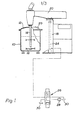
- Figure 1 is a schematic frontl elevation, partly in section, of mixing apparatus in accordance with the invention; and
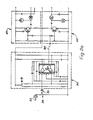
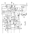
- Figures 2a and 2b when together comprise a diagram of circuitry for controlling the apparatus of Figure 1.

- Referring firstly to Figure 1, the apparatus comprises a
pot 10 for receiving liquid and finely divided materials to be mixed with the liquid. The pot has acover 12 which may have suitahle openings (not shown) for introduction of the materials. Avertical shaft 14 extends through thecover 12 and carries anagitator 16 which may be of any structure conventionally used in the art. Theshaft 14 is supported from acolumn 18 via acantilever arm 20 and is driven rotatably by an electric motor (not shown). Thearm 20 is movable upwardly and downwardly to vary the depth of immersion of theagitator 16 and suitable raising and lowering gear is provided for this purpose. The raising and lowering gear may take various forms and the illustrated embodiment employs a single actinghydraulic ram 24 whose cylinder is fixed and whose piston is connected to thearm 20. Hydraulic oil is supplied to theram 24 by apump 26 via an electricallyoperable spool valve 28. As shown, thevalve 28 is in a neutral condi- tion in which no oil is supplied to or withdrawn from theram 24, thepump 26 being connected directly tosump 30. When the spool valve is displaced upwardly, thepump 26 supplies oil to theram 24 to raise the agitator and when the valve is displaced downwardly from the neutral position, oil is withdrawn from theram 24 to lower theagitator 16. - The
valve 28 is controlled by the circuitry of Figure 2 which is designed to maintain the agitator at a level within the vessel which will give optimum mixing of the contents of the pot. The optimum level may vary, e.g. as more and more material is introduced into the vessel, which means that the vertical position of the agitator must be varied accordingly to maintain optimum mixing conditions. To achieve this, the noise level produced by the turbulence of the agitated contents of the vessel is monitored by means of amicrophone 30 and the circuitry of Figures 2a and 2b and thevalve 28 is operated so that the agitator is maintained at a level corresponding to a preselected range of noise levels, i.e. the noise level rage corresponding to the ooptimum vertical position of the agitator. This range can be readily determined on an empirical basis and typically will be in the region of 80 to 90 decibels. In general, thelevel will increase beyond the desired is too close to the liquid surface and will decrease when the agitator is too remote from the surface.
- The
microphone 30 is provided on thecover 12 above the level of the contents of the vessel so as to respond to the noise resulting from turbulence. Themicrophone 30 may be covered by a membrane or the like (not shown) to protect it from the harsh environment within the vessel. - Referring now to Figures 2a and 2b, the output of the
microphone 30 is connected toinput socket 32 and the low frequency components thereof, e.g. below 100 Hertz, are attenuated by filter capacitor 33. The filtered signal is amplified insection 34 which comprises a pair of serially- connected operational amplifiers on a commercially available IC747 chip. The input level of the microphone output can be varied by means of apotentiometer 36 which facilitates initial calibration of the circuitry. The amplified signal appears onlead 38 and is applied to two separate amplification andrectifier sections section 34 will be of the order of 200 and that ofsections sections IC555 timer 44, 46 which in addition to having a presettable timing function also, in effect, acts as a voltage level detector in the manner of a Schmitt trigger and gives well-defined output voltages (e.g. 0 and 15 volts). - The timer/
detector 44 is arranged to detect when the signal at pin 48 falls belew a preset threshold voltage which corresponds to the lower limit of the desired range of noise levels. When the signal applied to pin 48 falls below the threshold, the timer/detector 44 provides an output onpin 50 which energises relay RL1 and a signalling device in the form of an LER52 which may, for example, emit green light. In these circumstances, the timing function of thetimer 44 is effective to maintain the output onpin 50 for a preset time interval, e.g. 2 to 5 seconds, and upon timing out the output is removed at least temporarily depending on whether the input at pin 48 is still below the threshold - if it is then the output atpin 50 is restored to energise relay RL1 again for the preset timing interval and so on. The relay RL1 has a movable switch contact 54 associated with it which changes over from the illustrated position when relay RL1 is energised. When the input at pin 48 exceeds the threshold, the output atpin 50 is low, e.g. 0 volts, so that the relay RL1 is not energised in these circumstances. Because the IC555 timer 44 (and also 46) gives well-defined output voltage levels (e.g. 0 and 15 volts), hysteresis effects are avoided in the operation of the relay. - Whereas the timer/
detector 44 is used to detect when the noise level is below the desired range, the timer/detector 46 is used to detect noise levels above the desired range and, for this purpose, the output fromsection 42 is inverted insection 56 before being applied toinput pin 58. Also the signal level of the output fromsection 56 can be varied by means of apotentiometer 60 in order to render this high noise level portion of the circuitry less sensitive than the portion used to detect low noise levels. The timer/detector 46 operates similarly to the timer/detector 44 and provides the high output atpin 62 when the input atpin 58 is below a preset threshold (which may be different from that associated with timer/detector 44) and a low output when the input is above the threshold. In this case, because of the signal inversion, an input signal below the preset thresholds corresponds to a noise level above the desired range. The output atpin 62, when high, energises relay RL2 and LED64 which may for example emit red light. The timer 46 maintains the high output onpin 62 for a preset interval of time which, in this case, is preferably longer than that oftimer 44, e.g. 10 to 15 seconds. The relay RL2 has a contact 66 associated therewith which changes over from the illustrated position when relay RL2 is energised. - The circuitry is powered from the mains supply via on-off
switch 67, atransformer 68 and rectifier, filtering andsmoothing section 70 which includes avoltage regulator 72. The solenoid coils 28a and b ofvalve 28 are connected to the mains supply via manually operable switches PB1 and PB2 which normally occupy the position shown so that switch PBl connects coil 28h to fixed relay contact 66a via point Y and switch PB2 connects coil 28a to fixed relay contact 54a via point X. Thus, if relay RL1 operates,coil 28 is energised to changeoverspool valve 28 and effect raising of theagitator 16. Similarly if relay RL2 operates,coil 28b is energised to change over thevalve 28 and effect lowering of the agitntor. It will be noted that the relay switch contacts are wired so that operation of relay RL2 will override relay RL1. Further, if either of switches PB1 and PB2 is manually operated, both relays are overridden and the agitator can be raised or lowered under manual control independently of the noise level emitted by the contents of the vessel. - Operation of the equipment will be apparent from the foregoing description. Briefly however, when the noise level emitted by the agitated contents of the pot is within the range determined for optimum positioning of the
agitator 16, theIC555 timers 44, 46 both provide low outputs and relays RL1 and RL2 remain de-energised, as do LED52 and LED64. If however the noise level falls below or rises above the desired range, the input totimer 44 or 46 will be below the respective preset threshold and the associated relay will operate with consequent changeover of thevalve 28 to restore the agitator to a position where the noise level is within the desired range. During the raising or lowering operation, eitherdiode timer 44, 46 thus avoiding overshoot. - In some circumstances, it may be desirable to modify the above described servomechanical control of the agitator, in particular when the pot has been more or less filled to its maximum level. In this event, the optimum level of the agitator used during the addition of the material to the contents of the pot may not be suitable because once all the material has been added, good circulation of the contents throughout the body of the liquid becomes important whereas during the initial mixing stages turbulence at the surface of the liquid is important to reduce undesirable clotting and agglomeration. This is especially the case in relatively large vessels since, if the agitator is relatively close to the liquid's surface, poor circulation throughout the body of the liquid is likely.
- This problem may be solved by arranging for operation of the machine in two modes: a first mode as described above in which the agitator is constantly repositioned to maintain it at the optimum level and a second mode in which the agitator is deliberately shifted downwardly from the optimum level and then allowed t.o return gradually to that level under the control of the circuitry of Figures 2a and 2b. Thus, in the latter mode, means may be provided to override the circuitry of Figures 2a and 2b temporarily and operate
valve 28 to lower theagitator 16 to a position close to the base of the pot. The override signal is then removed so that the circuitry of Figures 2a and 2b becomes operative to restore the agitator to the optimum level. When operating in this mode, the arrangement may be such that, for example, the agitator is allowed to operate at optimum level for say 4 seconds, and is then lowered for an interval of say 8 seconds to the lower position at which it remains for say 4 seconds before the override signal is removed to allow the agitator to seek the optimum level again, whereupon the procedure is repeated. - Changeover of machine operation from the first mode to the second mode may be manually supervised or may be automatically controlled as part of a fully automated filling and mixing process, the change from the first to the second mode occurring after the pot has been filled to a predetermined level.
- As described above, the apparatus is shown as having only one agitator; however, it is to be understood that the invention is also applicable to apparatus having more than one rotor, for example a premixer disperser having a first rotor which is fixed in position (vertically) and driven through the base of the pot, this being operated to create the initial mixing of a batch of material loaded into the pot, and with a second rotor which extends through the top of the pot and which is raised and lowered as explained hereinabove.
Claims (10)
Applications Claiming Priority (4)
| Application Number | Priority Date | Filing Date | Title |
|---|---|---|---|
| GB3387677 | 1977-08-12 | ||
| GB3387677 | 1977-08-12 | ||
| GB1219878 | 1978-03-29 | ||
| GB1219878 | 1978-03-29 |
Publications (2)
| Publication Number | Publication Date |
|---|---|
| EP0000827A1 true EP0000827A1 (en) | 1979-02-21 |
| EP0000827B1 EP0000827B1 (en) | 1981-02-18 |
Family
ID=26248853
Family Applications (1)
| Application Number | Title | Priority Date | Filing Date |
|---|---|---|---|
| EP78300230A Expired EP0000827B1 (en) | 1977-08-12 | 1978-08-02 | Apparatus for the production of mixtures, dispersions and the like |
Country Status (3)
| Country | Link |
|---|---|
| EP (1) | EP0000827B1 (en) |
| DE (1) | DE2860534D1 (en) |
| GB (1) | GB2002246B (en) |
Cited By (8)
| Publication number | Priority date | Publication date | Assignee | Title |
|---|---|---|---|---|
| EP0057968A2 (en) * | 1981-02-11 | 1982-08-18 | The Mastermix Engineering Company Limited | Making paint or the like |
| EP0109168A2 (en) * | 1982-11-11 | 1984-05-23 | Netzsch Mastermix Limited | Apparatus for the production of mixture, dispersions and the like |
| EP0112619A2 (en) * | 1982-11-23 | 1984-07-04 | Netzsch Mastermix Limited | Apparatus for the production of mixture, dispersions and the like |
| EP0278374A2 (en) * | 1987-02-06 | 1988-08-17 | Pharmatest Apparatebau Gmbh | Device for testing the release of active components by pharmaceutical products |
| GB2220584A (en) * | 1988-07-15 | 1990-01-17 | Netzsch Mastermix Ltd | Mixing and dispersing apparatus |
| US5229122A (en) * | 1986-02-07 | 1993-07-20 | Burroughs Wellcome Co. | Pesticidal compositions |
| US6186334B1 (en) | 1997-12-17 | 2001-02-13 | Waeschle Gmbh | Method of and apparatus for screening bulk material |
| WO2004103727A2 (en) * | 2003-05-20 | 2004-12-02 | Adams Roger W | Paint container and colorant injector apparatus and method |
Families Citing this family (1)
| Publication number | Priority date | Publication date | Assignee | Title |
|---|---|---|---|---|
| DE3220453A1 (en) * | 1982-05-29 | 1983-12-01 | Janke & Kunkel GmbH & Co KG Ika - Werk, 7813 Staufen | STIRRER, IN PARTICULAR FOR LABORATORY OPERATION |
Citations (5)
| Publication number | Priority date | Publication date | Assignee | Title |
|---|---|---|---|---|
| US2637538A (en) * | 1950-09-29 | 1953-05-05 | Mixing Equipment Co Inc | Mixing apparatus |
| US3050264A (en) * | 1959-07-17 | 1962-08-21 | Vernie W Marcyes | Sound actuated control system for ball mill and the like |
| US3110481A (en) * | 1958-09-26 | 1963-11-12 | Westinghouse Electric Corp | Magnetic shaft damper |
| FR1398561A (en) * | 1964-06-12 | 1965-05-07 | Torrance And Sons Ltd | Improvements in apparatus for mixing, dispersing or dissolving |
| DE1607573A1 (en) * | 1967-12-01 | 1969-12-11 | Polysius Ag | Procedure and device for protecting external power mills against overload |
-
1978
- 1978-08-02 GB GB7831989A patent/GB2002246B/en not_active Expired
- 1978-08-02 EP EP78300230A patent/EP0000827B1/en not_active Expired
- 1978-08-02 DE DE7878300230T patent/DE2860534D1/en not_active Expired
Patent Citations (5)
| Publication number | Priority date | Publication date | Assignee | Title |
|---|---|---|---|---|
| US2637538A (en) * | 1950-09-29 | 1953-05-05 | Mixing Equipment Co Inc | Mixing apparatus |
| US3110481A (en) * | 1958-09-26 | 1963-11-12 | Westinghouse Electric Corp | Magnetic shaft damper |
| US3050264A (en) * | 1959-07-17 | 1962-08-21 | Vernie W Marcyes | Sound actuated control system for ball mill and the like |
| FR1398561A (en) * | 1964-06-12 | 1965-05-07 | Torrance And Sons Ltd | Improvements in apparatus for mixing, dispersing or dissolving |
| DE1607573A1 (en) * | 1967-12-01 | 1969-12-11 | Polysius Ag | Procedure and device for protecting external power mills against overload |
Cited By (14)
| Publication number | Priority date | Publication date | Assignee | Title |
|---|---|---|---|---|
| EP0057968A2 (en) * | 1981-02-11 | 1982-08-18 | The Mastermix Engineering Company Limited | Making paint or the like |
| EP0057968A3 (en) * | 1981-02-11 | 1984-05-23 | The Mastermix Engineering Company Limited | Making paint or the like |
| EP0109168A2 (en) * | 1982-11-11 | 1984-05-23 | Netzsch Mastermix Limited | Apparatus for the production of mixture, dispersions and the like |
| EP0109168A3 (en) * | 1982-11-11 | 1986-08-13 | The Mastermix Engineering Company Limited | Apparatus for the production of mixture, dispersions and the like |
| EP0112619A2 (en) * | 1982-11-23 | 1984-07-04 | Netzsch Mastermix Limited | Apparatus for the production of mixture, dispersions and the like |
| EP0112619A3 (en) * | 1982-11-23 | 1986-07-30 | Mastermix Limited | Apparatus for the production of mixture, dispersions and the like |
| US5229122A (en) * | 1986-02-07 | 1993-07-20 | Burroughs Wellcome Co. | Pesticidal compositions |
| EP0278374A3 (en) * | 1987-02-06 | 1989-03-01 | Pharmatest Apparatebau Gmbh | Device for testing the release of active components by pharmaceutical products |
| EP0278374A2 (en) * | 1987-02-06 | 1988-08-17 | Pharmatest Apparatebau Gmbh | Device for testing the release of active components by pharmaceutical products |
| GB2220584A (en) * | 1988-07-15 | 1990-01-17 | Netzsch Mastermix Ltd | Mixing and dispersing apparatus |
| US6186334B1 (en) | 1997-12-17 | 2001-02-13 | Waeschle Gmbh | Method of and apparatus for screening bulk material |
| WO2004103727A2 (en) * | 2003-05-20 | 2004-12-02 | Adams Roger W | Paint container and colorant injector apparatus and method |
| WO2004103727A3 (en) * | 2003-05-20 | 2005-08-11 | Roger W Adams | Paint container and colorant injector apparatus and method |
| US7086776B2 (en) | 2003-05-20 | 2006-08-08 | Adams Roger W | Paint container and colorant injector apparatus and method |
Also Published As
| Publication number | Publication date |
|---|---|
| GB2002246B (en) | 1982-01-13 |
| DE2860534D1 (en) | 1981-04-02 |
| EP0000827B1 (en) | 1981-02-18 |
| GB2002246A (en) | 1979-02-21 |
Similar Documents
| Publication | Publication Date | Title |
|---|---|---|
| EP0000827B1 (en) | Apparatus for the production of mixtures, dispersions and the like | |
| US5556198A (en) | Multipurpose food mixing appliance specially adapted for kneading dough | |
| US3821925A (en) | Apparatus for pressure cooking foods | |
| DE2932039A1 (en) | DEVICE FOR CONTROLLING THE COOKING COOKING TIME ON COOKED VESSEL | |
| US4108499A (en) | Method and control system for controlling a suspended implement | |
| US1139888A (en) | Automatic metal-feed for continuous casting-machines. | |
| US3727894A (en) | Apparatus for moistening mixable materials | |
| US5172497A (en) | Slurry density control system | |
| US3521696A (en) | Continuous casting line speed control | |
| US3516513A (en) | Method and apparatus for leveling self-frecting platform structures | |
| US2489776A (en) | Weight controlled container filling device | |
| KR900002100B1 (en) | Method and apparatus for controlling operation of disc refiner | |
| US3480212A (en) | Control apparatus | |
| US3308991A (en) | Blender for slurries and mixtures | |
| US3913380A (en) | Monitoring and blending of liquid fuel | |
| US4586187A (en) | Control apparatus for controlling movements of an electrode in an electric arc furnace | |
| EP0109168B1 (en) | Apparatus for the production of mixture, dispersions and the like | |
| US4029888A (en) | Arc furnace control system | |
| EP0032442A1 (en) | Electromagnetic casting apparatus and process | |
| JP2600188B2 (en) | Weight filling device | |
| US2812928A (en) | Electronic level-sensitive apparatus | |
| US4473104A (en) | Electromagnetic casting process and apparatus | |
| EP0855135A2 (en) | Irrigation control | |
| DE1028352B (en) | Electronic liquid level measuring device | |
| US3935677A (en) | Metallographic polisher with speed control |
Legal Events
| Date | Code | Title | Description |
|---|---|---|---|
| PUAI | Public reference made under article 153(3) epc to a published international application that has entered the european phase |
Free format text: ORIGINAL CODE: 0009012 |
|
| AK | Designated contracting states |
Designated state(s): BE CH DE FR LU NL SE |
|
| 17P | Request for examination filed | ||
| GRAA | (expected) grant |
Free format text: ORIGINAL CODE: 0009210 |
|
| AK | Designated contracting states |
Designated state(s): BE CH DE FR LU NL SE |
|
| PG25 | Lapsed in a contracting state [announced via postgrant information from national office to epo] |
Ref country code: SE Effective date: 19810218 |
|
| REF | Corresponds to: |
Ref document number: 2860534 Country of ref document: DE Date of ref document: 19810402 |
|
| PG25 | Lapsed in a contracting state [announced via postgrant information from national office to epo] |
Ref country code: LU Free format text: LAPSE BECAUSE OF NON-PAYMENT OF DUE FEES Effective date: 19810831 |
|
| REG | Reference to a national code |
Ref country code: CH Ref legal event code: PUE Owner name: MASTERMIX LIMITED |
|
| REG | Reference to a national code |
Ref country code: FR Ref legal event code: TP |
|
| BECN | Be: change of holder's name |
Effective date: 19840314 |
|
| REG | Reference to a national code |
Ref country code: CH Ref legal event code: PFA Free format text: NETZSCH MASTERMIX LIMITED |
|
| NLT1 | Nl: modifications of names registered in virtue of documents presented to the patent office pursuant to art. 16 a, paragraph 1 |
Owner name: NETZSCH MASTERMIX LIMITED TE WALSALL, GROOT-BRITTA |
|
| REG | Reference to a national code |
Ref country code: FR Ref legal event code: CD |
|
| PGFP | Annual fee paid to national office [announced via postgrant information from national office to epo] |
Ref country code: FR Payment date: 19900807 Year of fee payment: 13 |
|
| PGFP | Annual fee paid to national office [announced via postgrant information from national office to epo] |
Ref country code: CH Payment date: 19900824 Year of fee payment: 13 |
|
| PGFP | Annual fee paid to national office [announced via postgrant information from national office to epo] |
Ref country code: NL Payment date: 19900831 Year of fee payment: 13 |
|
| PGFP | Annual fee paid to national office [announced via postgrant information from national office to epo] |
Ref country code: BE Payment date: 19900904 Year of fee payment: 13 |
|
| PGFP | Annual fee paid to national office [announced via postgrant information from national office to epo] |
Ref country code: DE Payment date: 19900927 Year of fee payment: 13 |
|
| PG25 | Lapsed in a contracting state [announced via postgrant information from national office to epo] |
Ref country code: CH Effective date: 19910831 Ref country code: BE Effective date: 19910831 |
|
| BERE | Be: lapsed |
Owner name: NETZSCH MASTERMIX LTD Effective date: 19910831 |
|
| PG25 | Lapsed in a contracting state [announced via postgrant information from national office to epo] |
Ref country code: NL Effective date: 19920301 |
|
| NLV4 | Nl: lapsed or anulled due to non-payment of the annual fee | ||
| PG25 | Lapsed in a contracting state [announced via postgrant information from national office to epo] |
Ref country code: FR Effective date: 19920430 |
|
| REG | Reference to a national code |
Ref country code: CH Ref legal event code: PL |
|
| PG25 | Lapsed in a contracting state [announced via postgrant information from national office to epo] |
Ref country code: DE Effective date: 19920501 |
|
| REG | Reference to a national code |
Ref country code: FR Ref legal event code: ST |
|
| PLBE | No opposition filed within time limit |
Free format text: ORIGINAL CODE: 0009261 |
|
| STAA | Information on the status of an ep patent application or granted ep patent |
Free format text: STATUS: NO OPPOSITION FILED WITHIN TIME LIMIT |