EP0000631B1 - Xerographic copier including hot roll fuser - Google Patents
Xerographic copier including hot roll fuser Download PDFInfo
- Publication number
- EP0000631B1 EP0000631B1 EP78300138A EP78300138A EP0000631B1 EP 0000631 B1 EP0000631 B1 EP 0000631B1 EP 78300138 A EP78300138 A EP 78300138A EP 78300138 A EP78300138 A EP 78300138A EP 0000631 B1 EP0000631 B1 EP 0000631B1
- Authority
- EP
- European Patent Office
- Prior art keywords
- roll
- fuser
- frame
- hot roll
- links
- Prior art date
- Legal status (The legal status is an assumption and is not a legal conclusion. Google has not performed a legal analysis and makes no representation as to the accuracy of the status listed.)
- Expired
Links
Images


Classifications
-
- G—PHYSICS
- G03—PHOTOGRAPHY; CINEMATOGRAPHY; ANALOGOUS TECHNIQUES USING WAVES OTHER THAN OPTICAL WAVES; ELECTROGRAPHY; HOLOGRAPHY
- G03G—ELECTROGRAPHY; ELECTROPHOTOGRAPHY; MAGNETOGRAPHY
- G03G15/00—Apparatus for electrographic processes using a charge pattern
- G03G15/20—Apparatus for electrographic processes using a charge pattern for fixing, e.g. by using heat
- G03G15/2003—Apparatus for electrographic processes using a charge pattern for fixing, e.g. by using heat using heat
- G03G15/2014—Apparatus for electrographic processes using a charge pattern for fixing, e.g. by using heat using heat using contact heat
- G03G15/2017—Structural details of the fixing unit in general, e.g. cooling means, heat shielding means
- G03G15/2032—Retractable heating or pressure unit
- G03G15/2035—Retractable heating or pressure unit for maintenance purposes, e.g. for removing a jammed sheet
Landscapes
- Physics & Mathematics (AREA)
- General Physics & Mathematics (AREA)
- Fixing For Electrophotography (AREA)
Description
- The present invention relates to xerographic copiers, and in particular to such copiers incorporating fusers of the hot roll type.
- A hot roll fuser comprises a heatable roll and a back-up roll. In operation, these are positioned together to form a nip through which a copy sheet carrying a toned image passes. The toned image contacts the heatable roll to cause fusion of the toner to the sheet. The back-up roll normally has a metallic surface whereas the heatable roll has a softer surface of, for example, a polymeric material, to prevent toner offset to this roll. This relatively soft surface is subject to wear in operation of the fuser. When the fuser is designed to accept copy sheets of a single size, at least in the axial direction of the rolls, the length of the rolls can be chosen to correspond with the size of the sheets. Accordingly substantially the whole length of the rolls are used for each operation and wear is evently distributed along the heatable roll. If, however, the fuser is in a machine which produces copy sheets of differing dimensions, the whole length of the rolls contacts only the largest sheets applied thereto. In all other cases, the sheets are shorter than the lengths of the rolls, and this causes uneven wear of the hot roll surface. Such uneven wear has previously been recognised, and a remedy is shown in German Offenlegungsschrift No. 2440154. In the system shown therein, the heatable roll is mounted for axial displacement relative to the back-up roll. When wear occurs, the heatable roll can be shifted axially to a new position to offset the wear. The system employs a relatively complex mounting arrangement for the rolls using a special bearing system. The adjustment procedure is fairly complicated.
- The present invention is concerned with xerographic copying apparatus which is adaptable to minimise the above mentioned uneven wear. It employs an arrangement in which reconfiguration is accomplished far more easily than with the above mentioned prior art arrangement. The copying apparatus in accordance with the invention includes a hot roll fuser comprising a heatable roll, having a soft surface, and a backup roll, having a hard surface, and means for feeding copy paper sheets of differing dimensions carrying toned images to and through the fuser for fixing the toned images to the sheets, characterised by a frame carrying the heatable roll, said frame, together with the roll, being removably mountable in the fuser unit such as to permit end-to-end reversal of the heatable roll.
- It is noted that matter forming the subject of this specification also forms the subject of published European Patent Application No. 000632.
- An embodiment of the invention will now be described with reference to the accompanying drawings, in which:
- Fig. 1 is a general view of a xerographic copier incorporating a hot roll fuser assembly;
- Fig. 2 is a simplified cross-sectional view of the Fig. 1 fuser assembly;
- Fig. 3 is a diagrammatic view of the fuser assembly showing a roll closure mechanism;
- Fig. 4 is a diagrammatic view of a fuser assembly as in Fig. 3, but seen from the opposite side;
- Fig. 5 and 6 are exploded diagrammatic views of the solenoid, pivoting link and clutch shown in Fig. 4;
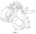
- Fig. 7 is a diagrammatic view of a mechanism used in conjucntion with the fuser assembly to move associated hardware to facilitate access to the hot roll and backup roll area;
- Fig. 8 is a diagrammatic view as in Fig. 7, with the associated hardware moved out of the way for access to the hot roll and cold roll;
- Fig. 9 is a perspective view of the fixed centre drive for producing rotation of the backup roll, and also shows the backup roll's scraping blade cleaner and the fuser's paper exit guide transport roller;
- Fig. 10 is a partially fragmented diagrammatic view showing removal of the subframe from the mainframe in the fuser assembly;
- Fig.11 is a partially fragmented, exploded perspective view of the positioning surfaces and pin in the mainframe for supporting the subframe;
- Fig. 12 is an exploded perspective view partially in section showing the U-shaped metal subframe member and the handle thereon for effecting removal of the subframe from the mainframe of Fig. 10; and
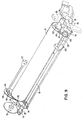
- Fig. 13 is an overall perspective view of the fusing assembly.
- Fig. 1 is a general view of
xerographic copier 10 incorporating afuser assembly 12, which is shown in its extended or pulled-out position in front of the copier, and is slidably supported withincopier 10 by apparatus shown for purposes of simplicity. This is a non-operating position adapted to facilitate inspection, cleaning, repair and/or sheet jam clearance. - The slidably supported
fuser assembly 12 includes ahot roll 14 and abackup roll 16. Generally,hot roll 14 is heated to an accurately controlled temperature by aninternal heater 15, as seen in Fig. 2, and an associated temperature control system which is not shown.Hot roll 14 preferably includes a deformable external surface formed as a thin elastomeric surface. This surface is designed to engage the toned image side of a copy sheet.Hot roll 14, acting in concert withbackup roll 16, fuses the image onto the copy sheet and readily releases the sheet with minimum adherence of residual toner to the hot roll. As is conventional in hot roll fusers, the sheets toned side faces the hot roll. -
Backup roll 16 is preferably a relatively cool and rigid roll. Bothrolls rolls - The fusing nip formed by
rolls - Fig. 2 shows the fusing nip closed. Rigid back- up
roll 16 is shown to be in contact with resilienthot roll 14, thereby deforming the surface ofhot roll 14 so as to form afusing nip 18 of a certain width, measured in the direction ofsheet movement 19. Feedroller 20 cooperating withidler roller 21 continuessheet movement 19 until a copy passing therethrough is free offusing nip 18 and has passed through fuser exit-way 22. - In Fig. 3,
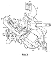
hot roll 14 is removably, rotationally mounted on a fixed position axis inmounting blocks 23 which are supported by way of positioningsurfaces 24 formed in the ends of a single piece mountingmainframe member 26. Thismainframe member 26 includes a hanger which supports the fuser assembly by way of telescopingrails 30.Frame member 26 also includesrollers 32 which cooperate with a copier frame member to stablize the fuser assembly position within the copier. - As seen in Fig. 3 and 13,
roll 16 is rotationally supported, onaxis 34, by way of pivotingcradle arms 36 at each end offrame member 26. These cradle arms are pivoted on the frame member ataxis 38.Pivot arms 40, at each end ofmainframe member 26, are pivotably mounted to the frame member by way ofpivot 42.Pivot arms 40 have downwardly extendingprojections 41 which supportrollers 44 which cooperate with nip opening and closingcams 46. The other ends ofpivot arms 40 have mounted thereonends 48 ofcompressible springs 50. Theother end 52 ofsprings 50 operate oncradle arms 36 to causearms 36 to rotate clockwise aboutaxis 38, as the fuser nip is closed. In addition to rotatingarms 36,springs 50 provide controlled pressure to backuproll 16 throughaxis 34, and consequently the pressure to fusingnip 18 is controlled. Springs 53, positioned betweenhanger 28 andpivot arms 40, provide an additional closing force tofuser nip 18. - The closing of
fusing nip 18 is achieved bycams 46 which are rotationally mounted onaxis 38. These cams include alow point 54 which, when positoned to cooperate withroller 44, establish a nip-open condition. To close the nip,solenoid 56 is energized and clutch 58, shown in Fig. 4-6, operates to rotatecams 46, in Fig. 3, clockwise 235° (counterclockwise if observing Fig. 4) to the position shown, causingnip 18 to close. - During nip closure, pivot arms 40 (see Fig. 3) rotate counterclockwise causing fixed-
position pivot 42,spring pivot 60 andaxis 34 to come into substantial alignment. However,pivot point 60 does not move over-center. Thus, subsequent rotation ofcams 46, back to the nipopen cam position 54, as a result of the de-energization ofsolenoid 56, allowsspring 50 to rotatepivot arms 40 clockwise (when observed on Fig. 3) aboutpivot 42, openingfusing nip 18. - In Fig. 5 and 6,
cams 46 are connected to rotate onaxis 38 as long asclutch member 58 is free to rotate. In the de-energized position ofsolenoid 58, (Fig. 5)dog 62 is held against rotation bytap 70 on pivotinglink 66.Link 66 is pivoted atfixed position pivot 68. Whensolenoid 56 is energized, (Fig. 6)clutch member 58 andcam 46 are driven 235° untildog 62 engagestab 64. Fusing nip 18 is now closed. Subsequently, when it is desired to open the fusing nip,solenoid 56 is de-energized, link 66 returns to its de-energized position, andclutch member 58 rotates until it is stopped bytab 70. Fusing nip 18 is now opened. - In the fragmented portion of Fig. 4, a folded
handle 72, for manually removinghot roll 14, is shown. The use of this handle for removinghot roll 14 from the fusing assembly will be explained hereinafter. - In Fig. 13, a manually movable, rod-
like handle 74 extends the length of the fuser assembly, parallel toaxis 34. Opposite ends of this handle are attached tomovable links 76, at each end of the fuser assembly. In Fig. 7 and 8 it is seen that these links are pivoted on fixed-position axis 78. Both of the links have anotch 80, apivot point 82 for one end of adrive arm 84. In Fig. 7, links 76 are shown in their operative positions, whereinhot roll 14 detach bar (not shown) and the fuser's output sheet transport channel (not shown) are located closely adjacent the down stream portion of fusing nip 18 (shown closed). - In Fig. 7, 8 and 13,
links 88 are pivoted on fixed-position axis 90. Each oflinks 88 has aprojection 92 thereon for holding mountingblocks 23 securely withinmainframe 26.Links 88 carry lockingpins 96 which lock links 88 (and the detach bar) in operative position by virtue of an interface at 98 betweenpin 96 andpivotable links 100.Links 100 are pivoted on fixed-position axis 102. - The ends of the above-mentioned output sheet transport channel are attached to
links 106. These links are pivoted onbackup roll axis 34.Axis 34 is not a fixed-positioned axis because during nip closure,axis 34 moves a slight distance downward, as represented byarrow 108 in Fig. 7. - The upper end of
links 106 carry alocking pin 110, cooperating withnotch 80 formed inlinks 76. The lower end oflinks 106 carrylower pivot axis 112 for the end ofdrive arm 84 that isopposite pivot point 82. - In Fig. 8, two tension springs 114 extend between
pins 116 carried bylinks 76 and pins 118 carried bylinks 100. The springs provide a closing force betweenlinks 76 and links 100. In addition to providing a closing force betweenlinks 76 andlinks 100, springs 114 provide a contacting force betweenlinks 88 andpivotable links 100. The above-mentionedinterface 98 is created by these latter two sets of links. - In order to move the above-mentioned (but not shown) detach bar and output sheet transport channel out of the way for jam clearance or to remove
hot roll 14, the above-mentioned rod-like handle 74 is lifted up and rotated counterclockwise about fixed-position axis 78, to the position shown in Fig. 8. This causes the detach bar to generally rotate clockwise abouthot roll 14 away from fusing nip 18, and the output sheet transport channel to generally rotate counterclockwise aboutbackup roll 16. - During such movement, pins 116 on
links 76 engagelinks 100 and cause these links to privot counterclockwise about their fixed-position axis 102. As a result,interface 98, as seen in Fig.7, created by contact betweenpins 98 and pivotedlinks 100 is broken. In Fig. 8, as handle-actuatedlinks 76 continue to rotate conterclockwise,notches 80free pins 110. Conterclockwise rotation oflinks 76 transmits counterclockwise rotation tolinks 106 by virtue ofdrive arms 84. Aspivot axis 112 moves counterclockwise as represented byarrow 120 in Fig. 7, to its position in Fig. 8,links 106 is pivoted clear of fusingnip 18. As counterclockwise rotation oflinks 76 continues, surfaces 122 formed thereon engage lockingpin 96, causinglinks 88 to rotate clockwise about their fixed-position axis 90. - The detach bar and output sheet transport channel have now been moved out of the fusing nip for jam clearance. In addition, link 88 has been pivoted clockwise, eliminating the interface between
projection 92 onlinks 88 and mountingblocks 23.Links 88 can now be manually rotated clockwise, as represented byarrow 124 in Fig. 7, in order thathot roll 14 can be removed frommainframe 26. - In summary,
interface 98 locks the detach bar in operative position, notch 80 and pin 110 lock the output sheet transport channel in operative position,spring 114maintans interface 98, pin 116 lifts link 100 to interruptinterface 98, counterclockwise rotation oflink 76 freespin 110 and rotates link 106 by virtue ofdrive arm 84, and counterclockwise rotation oflink 76 rotates link 88 clockwise as a result of interference with lockingpin 96. - Fig. 9 shows the fixed center drives for (1) producing rotation of the fuser's
backup roll 16, (2) producing oscillatory movement of the backup roll'sscraping blade cleaner 126; and (3) producing rotation of the fuser's paper exit guidetransport roller 20.Roller 20 is supported by the exit paper transport guides, and engages the non- toner side of a sheet, as the sheet emerges from fusingnip 18. Additional information pertaining to theblade cleaner 126 appears in IBM Technical Disclosure Bulletin, Vol. 18, No. 2, July 1975, pp 326-327. - Counterclockwise rotation of
backup roll 16 is produced bygear 132 which meshes with continuously drivegear 134.Gear 132 is connected to the backup roll'saxis 34 and causes counterclockwise rotation of this roll. When the fusing nip is being closed or opened, the backup roll'srotational axis 34 moves in an arc aboutaxis 38. Thus,gear 132 merely rolls about itsmeshing gear 134. -
Cleaner 126 is supported by doublehelix lead screw 138. This lead screw is driven in a counterclockwise direction by virtue of gears 140-142 withgear 140 being fixedly mounted on an end oflead screw 138,gear 141 being rotatively mounted on fixedaxis 144 andgear 142 being fixedly mounted onaxis 34. Since all of these gears are carried bycradle arm 36, a fixed center relationship is maintained during nip opening and closing. - As a sheet of newly fused copy paper emerges from the fusing nip, and as it is driven by counterclockwise rotation of
backup roll 16, its leading edge is guided into the output sheet transport channel (not shown in Fig. 9). This sheet channel is supported by pivotinglinks 106.Links 106 supported at the rear end of the fuser, and shown in Fig. 9 and 13, carry a pair of gears 146,148 which mesh with agear 150 which is integral with back-up roll 16. Counterclockwise rotation of sheet transport roller 128 bygears idler roller 21, shown in Fig. 2, to trap the copy sheet therebetween. The idler roller engages the toned side of the copy sheet. - When the fuser's sheet detach bar and output sheet transport channel are manually moved out of the way, as for jam clearance,
links 106 rotate in a counterclockwise direction as discussed above with reference to Fig. 7 and 8. Sincelink 106 pivots about the backup roll'srotational axis 34, a fixed center is maintained for gears 146-150, and gears 146 and 148 merely rotate in a circle aboutgear 150. Consequently, a constant center distance between the gears is maintained andtransport roller 20 is driven with minimum backlash by the gearing. - The fuser's
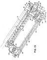
main frame member 26, shown in Fig. 10 and 11, comprises a central portion surrounding, but spaced from, the surface ofhot roll 14 and having upstanding end flanges establishing the various rotational axes of the backup roll and its associated structure. These end flanges include U-shaped slots or positioning surfaces 24 adapted to receive the ends of the reversible hot roll. - With reference to Fig. 12,
hot roll 14 is rotationally mounted in rigidU-shaped subframe member 152 which is symmetrically located between positioning surfaces 24.Subframe 152 is locked tomainframe 26 and is unlocked therefrom by rotation ofrotatable handle 74. Ahandle 154 shown folded in Fig. 10 and shown extended in Fig. 12, is mounted on the central portion ofsubframe member 152. - Each end of the hot roll is supported for substantially frictionous rotation in metal end blocks 23. End blocks 23 each have a stub shaft which fit into bearings at both ends of
hot roll 14.Hot roll 14 is easily replaceable because metal end blocks 23 are removable fromsubframe 152. These end blocks are substantially identical, the only exception being that one end block cooperates with ahelix compression spring 160 which axially biaseshot roll 14 towards the other end block for retention purposes. End blocks 23 nonrotationallysupport heating element 15, as also seen in Fig. 2, on the hot roll's axis of rotation. A hot roll core temperature sensor (not shown) is mounted onmainframe 26 underhot roll 14.Hot roll 14 is driven in a counterclockwise direction by frictional engagement with counterclockwiserotating backup roll 16 when the fusing nip is closed. - As seen in Fig. 12, both end blocks 23 have a mounting
channel 164.Channels 164 are of uniform cross-section and run perpendicular to the hot roll's axis of rotation. As shown in Fig. 10 and 11, the back mounting channel only ofmainframe member 26 includes apositioning pin 166 adapted to mate withchannel 164 in the end block adjacenthelix compression spring 160. The front positioning channel ofmainframe member 26, however, does not include such a positioning pin. Each end of thereversible subframe member 152, in Fig. 12, includes anelectrical connector portion 168, one of which is exploded and separated fromend block 23 to illustrateelectrical connector 170.Connector 172 is insulatively mounted on the mainframe member's forward end flange. The rear one of theseconnectors 168 is maintained in a fixed position by virtue of locking engagement betweenchannel 164 andpin 166.Electrical connector 170 experiences movement along the axis of the hot roll as the temperature of the hot roll'sU-shaped subframe member 152 changes. MetallicU-shaped subframe member 152 expands and contracts with temperature changes. However, sinceconnector member 172 has a channel extending in a direction parallel to the axis of the hot roll, sliding movement ofconnector 170 within the channel ofmember 172 is accommodated. - Paper is fed through the copier with its long dimension parallel to the hot roll's rotational axis, and with sheets of various sizes referenced to a common rear edge (corresponding to the common corner registration for all original documents to be copied on the master document support glass). This rear edge is indicated by
broken line 174 in Fig. 12. The forward edge of a 216 mm x 280 mm sheet of paper would reside atbroken line 176, whereas the forward edge of 216 mm x 355 mm sheet of paper would reside atbroken line 178. The hot roll's variable forward working area 176-178 makes it desirable to reversehot roll 14, end for end, periodically to distribute wear on the hot roll. - Before removing
subframe 152 andhot roll 14 out of thefuser assembly 12,subframe 152 is unlocked frommainframe 26 by actuatingrotatable handle 74 andmovable links 76 which rotatelinks 88 clear of mountingblocks 23. A shroud (not shown) which overlieshot roll 14 is pivoted clear of the roll and foldable handle 154 is unfolded to allow for the lifting ofhot roll 14, includingsubframe 152, out ofmain frame 26. With reference to Fig. 12, assubframe 152 is lifted, the connection betweenpositioning pin 166 andchannel 164 inend block 23 is broken. The electrical connection between the male and female connectors on theother end block 23 andmain frame 26 respectively, is also broken. The upward motion ofsubframe 152 continues and end blocks 23 continue sliding until free of positioning surfaces 24. Once out ofmainframe 26 and the fusing area,subframe 152 is reversed, end for end. After reversal ofsubframe 152, the above steps are reversed untilsubframe 152 is again locked tomain frame 26. Even through the handle for liftingsubframe 152 out of the copier is shown and described as being permanently attached tosubframe 152, it should be understood by those having skill in the art that modifications to the handle-subframe configuration can be made. For example, handle 154 could be detachable and stored until needed to removesubframe 152 from the copier. These simple manual steps allow hot roll reversal to be accomplished within a short period of time and also reduce the risk of component damage due to handling. Additionally, the hot roll core temperature sensor is not disturbed during reversal of the hot roll.
Claims (6)
Applications Claiming Priority (2)
| Application Number | Priority Date | Filing Date | Title |
|---|---|---|---|
| US05/820,272 US4121089A (en) | 1977-07-29 | 1977-07-29 | Apparatus for the reversal of a hot roll in a fusing assembly |
| US820272 | 1977-07-29 |
Publications (2)
| Publication Number | Publication Date |
|---|---|
| EP0000631A1 EP0000631A1 (en) | 1979-02-07 |
| EP0000631B1 true EP0000631B1 (en) | 1981-03-11 |
Family
ID=25230355
Family Applications (1)
| Application Number | Title | Priority Date | Filing Date |
|---|---|---|---|
| EP78300138A Expired EP0000631B1 (en) | 1977-07-29 | 1978-07-10 | Xerographic copier including hot roll fuser |
Country Status (9)
| Country | Link |
|---|---|
| US (1) | US4121089A (en) |
| EP (1) | EP0000631B1 (en) |
| JP (1) | JPS598834B2 (en) |
| AR (1) | AR219534A1 (en) |
| AU (1) | AU515273B2 (en) |
| BR (1) | BR7804907A (en) |
| CA (1) | CA1101921A (en) |
| DE (1) | DE2860519D1 (en) |
| IT (1) | IT1112267B (en) |
Families Citing this family (17)
| Publication number | Priority date | Publication date | Assignee | Title |
|---|---|---|---|---|
| JPS55153975A (en) * | 1979-05-17 | 1980-12-01 | Canon Inc | Picture image forming device |
| US4392739A (en) * | 1980-04-30 | 1983-07-12 | International Business Machines Corporation | Electromechanically operated fuser roll closure |
| US4363549A (en) * | 1980-04-30 | 1982-12-14 | International Business Machines Corporation | Electromechanically operated fuser roll closure |
| JPS56156862A (en) * | 1980-05-07 | 1981-12-03 | Toshiba Corp | Fixing device |
| JPS5772168A (en) * | 1980-10-22 | 1982-05-06 | Ricoh Co Ltd | Roller pressing device |
| FR2580228B1 (en) * | 1985-04-12 | 1987-05-22 | Ecamo | THERMOGRAVING MACHINE FOR RELIEF PRINTING |
| JP2868541B2 (en) * | 1989-09-16 | 1999-03-10 | キヤノン株式会社 | Fuser |
| EP0505404B1 (en) * | 1989-12-13 | 1994-06-01 | Siemens Nixdorf Informationssysteme Aktiengesellschaft | Fixing station for an electrophotographic printer or copier |
| DE4027770A1 (en) | 1990-09-01 | 1992-03-05 | Basf Lacke & Farben | LIQUID, RADIANT-COVERABLE COATING MEASUREMENT FOR THE COATING OF GLASS SURFACES |
| US5104112A (en) * | 1990-11-21 | 1992-04-14 | Pitney Bowes Inc. | Document feeder having reversibly positioned direct drive separator assembly motor |
| US5305065A (en) * | 1992-01-31 | 1994-04-19 | Eastman Kodak Company | Toner image fuser and cartridge for image-forming apparatus |
| JPH06507029A (en) * | 1992-01-31 | 1994-08-04 | イーストマン・コダック・カンパニー | Fusing roller cartridge for fusing equipment and fusing equipment |
| US5206477A (en) * | 1992-06-05 | 1993-04-27 | Eastman Kodak Company | Apparatus and method for replacing a fuser bar without tools |
| KR100196570B1 (en) * | 1996-09-02 | 1999-06-15 | 윤종용 | Fuser of electrophotographic processor |
| JP2000010376A (en) * | 1998-06-26 | 2000-01-14 | Fujitsu Ltd | Image forming device |
| JP4596022B2 (en) * | 2008-03-11 | 2010-12-08 | ブラザー工業株式会社 | Image forming apparatus |
| JP5493921B2 (en) * | 2010-01-29 | 2014-05-14 | 株式会社リコー | Roller replacement aid for fixing device |
Family Cites Families (6)
| Publication number | Priority date | Publication date | Assignee | Title |
|---|---|---|---|---|
| US3324791A (en) * | 1964-12-31 | 1967-06-13 | Xerox Corp | Xerographic roller fuser drive apparatus |
| DE2440154C3 (en) * | 1973-10-18 | 1979-01-25 | Xerox Corp., Rochester, N.Y. (V.St.A.) | Copier with fuser |
| US3856462A (en) * | 1973-10-18 | 1974-12-24 | Xerox Corp | Reproduction machine fuser |
| US3973844A (en) * | 1974-05-28 | 1976-08-10 | Xerox Corporation | Latching mechanism for the backup roll of a roll fuser employed in a copier apparatus |
| US3912901A (en) * | 1974-07-15 | 1975-10-14 | Xerox Corp | Pfa teflon sleeved chow pressure roll |
| JPS51145324A (en) * | 1975-06-10 | 1976-12-14 | Ricoh Co Ltd | Pressure regulating device for reproduction machine |
-
1977
- 1977-07-29 US US05/820,272 patent/US4121089A/en not_active Expired - Lifetime
-
1978
- 1978-04-24 CA CA301,786A patent/CA1101921A/en not_active Expired
- 1978-04-28 AU AU35558/78A patent/AU515273B2/en not_active Expired
- 1978-06-23 IT IT24889/78A patent/IT1112267B/en active
- 1978-06-26 JP JP53076611A patent/JPS598834B2/en not_active Expired
- 1978-06-30 AR AR272769A patent/AR219534A1/en active
- 1978-07-10 DE DE7878300138T patent/DE2860519D1/en not_active Expired
- 1978-07-10 EP EP78300138A patent/EP0000631B1/en not_active Expired
- 1978-07-31 BR BR7804907A patent/BR7804907A/en unknown
Also Published As
| Publication number | Publication date |
|---|---|
| AU515273B2 (en) | 1981-03-26 |
| IT7824889A0 (en) | 1978-06-23 |
| CA1101921A (en) | 1981-05-26 |
| AU3555878A (en) | 1979-11-01 |
| JPS598834B2 (en) | 1984-02-27 |
| AR219534A1 (en) | 1980-08-29 |
| JPS5425843A (en) | 1979-02-27 |
| DE2860519D1 (en) | 1981-04-09 |
| EP0000631A1 (en) | 1979-02-07 |
| BR7804907A (en) | 1979-04-10 |
| US4121089A (en) | 1978-10-17 |
| IT1112267B (en) | 1986-01-13 |
Similar Documents
| Publication | Publication Date | Title |
|---|---|---|
| EP0000631B1 (en) | Xerographic copier including hot roll fuser | |
| US4145181A (en) | Apparatus to facilitate jam recovery and hot roll reversal in a fusing assembly | |
| US4965640A (en) | Image forming apparatus including detachable toner fixing unit | |
| US4154575A (en) | Hot roll fuser roll closure apparatus | |
| US4110068A (en) | Hot roller fuser having manually operable jam clearance mechanism | |
| JPH0444076A (en) | Heating device | |
| JPH0444082A (en) | Heating device | |
| US20100054830A1 (en) | Blade engagement apparatus for image forming machines | |
| US7917049B2 (en) | Variable interference cleaning blade method | |
| US5835835A (en) | Fixing unit having press roller opening/closing mechanisms | |
| EP0000632B1 (en) | Hot roll fuser for a xerographic copier | |
| US4498757A (en) | Demountable, modular toner-fuser assembly for electrographic print apparatus | |
| EP1213625A2 (en) | Recording medium conveying mechanism and image forming apparatus using the same | |
| JP2004340997A (en) | Attaching and detaching mechanism for fixing unit | |
| JPH10301432A (en) | Electrophotographic device | |
| JPH02103076A (en) | Continuous recording paper retreating mechanism using continuous recording paper | |
| US3951538A (en) | Permanently nipped contact image fuser system incorporating a one-way clutch | |
| US5257071A (en) | Pivotal photoconductor belt assembly | |
| JPH11242402A (en) | Image forming device and fixing device | |
| US6430385B1 (en) | Wick roller assembly for an electrophotographic machine | |
| CA1059573A (en) | Cleaning structure for an elastomeric fusing member | |
| JPH0519658A (en) | Image recording device | |
| JP2002229371A (en) | Fuser release agent management system with driven release agent supply roll | |
| JP2681954B2 (en) | Paper jam removal structure | |
| JPH0532849Y2 (en) |
Legal Events
| Date | Code | Title | Description |
|---|---|---|---|
| PUAI | Public reference made under article 153(3) epc to a published international application that has entered the european phase |
Free format text: ORIGINAL CODE: 0009012 |
|
| AK | Designated contracting states |
Designated state(s): DE FR GB |
|
| 17P | Request for examination filed | ||
| GRAA | (expected) grant |
Free format text: ORIGINAL CODE: 0009210 |
|
| AK | Designated contracting states |
Designated state(s): DE FR GB |
|
| REF | Corresponds to: |
Ref document number: 2860519 Country of ref document: DE Date of ref document: 19810409 |
|
| PGFP | Annual fee paid to national office [announced via postgrant information from national office to epo] |
Ref country code: FR Payment date: 19890628 Year of fee payment: 12 |
|
| PGFP | Annual fee paid to national office [announced via postgrant information from national office to epo] |
Ref country code: GB Payment date: 19890630 Year of fee payment: 12 |
|
| PGFP | Annual fee paid to national office [announced via postgrant information from national office to epo] |
Ref country code: DE Payment date: 19890805 Year of fee payment: 12 |
|
| PG25 | Lapsed in a contracting state [announced via postgrant information from national office to epo] |
Ref country code: GB Effective date: 19900710 |
|
| GBPC | Gb: european patent ceased through non-payment of renewal fee | ||
| PG25 | Lapsed in a contracting state [announced via postgrant information from national office to epo] |
Ref country code: FR Effective date: 19910329 |
|
| PG25 | Lapsed in a contracting state [announced via postgrant information from national office to epo] |
Ref country code: DE Effective date: 19910403 |
|
| REG | Reference to a national code |
Ref country code: FR Ref legal event code: ST |
|
| PLBE | No opposition filed within time limit |
Free format text: ORIGINAL CODE: 0009261 |
|
| STAA | Information on the status of an ep patent application or granted ep patent |
Free format text: STATUS: NO OPPOSITION FILED WITHIN TIME LIMIT |