EP0000570A1 - Original of an optical information carrier and process for realising this original - Google Patents
Original of an optical information carrier and process for realising this original Download PDFInfo
- Publication number
- EP0000570A1 EP0000570A1 EP78100480A EP78100480A EP0000570A1 EP 0000570 A1 EP0000570 A1 EP 0000570A1 EP 78100480 A EP78100480 A EP 78100480A EP 78100480 A EP78100480 A EP 78100480A EP 0000570 A1 EP0000570 A1 EP 0000570A1
- Authority
- EP
- European Patent Office
- Prior art keywords
- relief
- original
- partial images
- areas
- recording layer
- Prior art date
- Legal status (The legal status is an assumption and is not a legal conclusion. Google has not performed a legal analysis and makes no representation as to the accuracy of the status listed.)
- Granted
Links
- 238000000034 method Methods 0.000 title claims description 15
- 230000003287 optical effect Effects 0.000 title claims description 4
- 239000003086 colorant Substances 0.000 claims abstract description 49
- 238000000926 separation method Methods 0.000 claims abstract description 20
- 238000004519 manufacturing process Methods 0.000 claims abstract description 7
- 239000012876 carrier material Substances 0.000 claims abstract description 3
- 235000005811 Viola adunca Nutrition 0.000 claims description 11
- 240000009038 Viola odorata Species 0.000 claims description 11
- 235000013487 Viola odorata Nutrition 0.000 claims description 11
- 235000002254 Viola papilionacea Nutrition 0.000 claims description 11
- 230000003595 spectral effect Effects 0.000 claims description 4
- 238000011161 development Methods 0.000 claims description 2
- 229920002120 photoresistant polymer Polymers 0.000 description 13
- PXHVJJICTQNCMI-UHFFFAOYSA-N Nickel Chemical compound [Ni] PXHVJJICTQNCMI-UHFFFAOYSA-N 0.000 description 10
- 239000000654 additive Substances 0.000 description 8
- 230000000996 additive effect Effects 0.000 description 8
- 239000002184 metal Substances 0.000 description 6
- 229910052751 metal Inorganic materials 0.000 description 6
- 229910052759 nickel Inorganic materials 0.000 description 5
- 239000004800 polyvinyl chloride Substances 0.000 description 5
- 229920000915 polyvinyl chloride Polymers 0.000 description 5
- 244000172533 Viola sororia Species 0.000 description 4
- 230000015572 biosynthetic process Effects 0.000 description 4
- 238000004049 embossing Methods 0.000 description 4
- 239000011521 glass Substances 0.000 description 4
- 239000000463 material Substances 0.000 description 4
- 239000011888 foil Substances 0.000 description 3
- 229920001169 thermoplastic Polymers 0.000 description 3
- 239000004416 thermosoftening plastic Substances 0.000 description 3
- 239000011248 coating agent Substances 0.000 description 2
- 238000000576 coating method Methods 0.000 description 2
- 230000000694 effects Effects 0.000 description 2
- 238000002474 experimental method Methods 0.000 description 2
- 239000011159 matrix material Substances 0.000 description 2
- RYGMFSIKBFXOCR-UHFFFAOYSA-N Copper Chemical compound [Cu] RYGMFSIKBFXOCR-UHFFFAOYSA-N 0.000 description 1
- BQCADISMDOOEFD-UHFFFAOYSA-N Silver Chemical compound [Ag] BQCADISMDOOEFD-UHFFFAOYSA-N 0.000 description 1
- 241000394567 Viola pubescens Species 0.000 description 1
- 230000005540 biological transmission Effects 0.000 description 1
- 229910052802 copper Inorganic materials 0.000 description 1
- 239000010949 copper Substances 0.000 description 1
- 238000000354 decomposition reaction Methods 0.000 description 1
- 230000003247 decreasing effect Effects 0.000 description 1
- 238000013461 design Methods 0.000 description 1
- 238000001035 drying Methods 0.000 description 1
- 238000003384 imaging method Methods 0.000 description 1
- 239000000203 mixture Substances 0.000 description 1
- 230000005693 optoelectronics Effects 0.000 description 1
- 229920000728 polyester Polymers 0.000 description 1
- 229920006267 polyester film Polymers 0.000 description 1
- 238000009877 rendering Methods 0.000 description 1
- 238000012216 screening Methods 0.000 description 1
- 229910052709 silver Inorganic materials 0.000 description 1
- 239000004332 silver Substances 0.000 description 1
- 238000009987 spinning Methods 0.000 description 1
- 238000003860 storage Methods 0.000 description 1
- 238000012360 testing method Methods 0.000 description 1
Images

Classifications
-
- G—PHYSICS
- G03—PHOTOGRAPHY; CINEMATOGRAPHY; ANALOGOUS TECHNIQUES USING WAVES OTHER THAN OPTICAL WAVES; ELECTROGRAPHY; HOLOGRAPHY
- G03F—PHOTOMECHANICAL PRODUCTION OF TEXTURED OR PATTERNED SURFACES, e.g. FOR PRINTING, FOR PROCESSING OF SEMICONDUCTOR DEVICES; MATERIALS THEREFOR; ORIGINALS THEREFOR; APPARATUS SPECIALLY ADAPTED THEREFOR
- G03F7/00—Photomechanical, e.g. photolithographic, production of textured or patterned surfaces, e.g. printing surfaces; Materials therefor, e.g. comprising photoresists; Apparatus specially adapted therefor
- G03F7/0005—Production of optical devices or components in so far as characterised by the lithographic processes or materials used therefor
- G03F7/001—Phase modulating patterns, e.g. refractive index patterns
-
- G—PHYSICS
- G03—PHOTOGRAPHY; CINEMATOGRAPHY; ANALOGOUS TECHNIQUES USING WAVES OTHER THAN OPTICAL WAVES; ELECTROGRAPHY; HOLOGRAPHY
- G03C—PHOTOSENSITIVE MATERIALS FOR PHOTOGRAPHIC PURPOSES; PHOTOGRAPHIC PROCESSES, e.g. CINE, X-RAY, COLOUR, STEREO-PHOTOGRAPHIC PROCESSES; AUXILIARY PROCESSES IN PHOTOGRAPHY
- G03C9/00—Stereo-photographic or similar processes
Definitions
- the invention relates to an original one.
- Information carrier consisting of a recording layer applied to a carrier material, which contains a relief image representing the information, the relief image being composed of a plurality of relief partial images adjoining one another without overlap in one plane, to which a relief grid with different lattice depths in the areas of the individual relief partial images is superimposed, and a method for producing the original.
- a nickel matrix with different relief depth is created separately, with which the separate embossed images are created.
- the relief depths are different, with the relief depth being greatest for the cyan extract and smallest for the yellow extract.
- a disadvantage that complicates the introduction of this technique is the complex manufacturing process with three completely separate work steps for producing the individual embossed relief images corresponding to the color separations. Another disadvantage is that the three separate relief images are put together to fit the duplicate image required for the color projection.
- the relief image is then composed of the relief partial images corresponding to the individual color separations in such a way that differently colored areas, which in the case of rasterized images can also be halftone dots, are arranged in one plane, the differently colored areas not overlapping but at most touching.
- Relief images of this type are very well suited for displaying flat, multicolored templates, such as graphic representations, in the form of relief grid structures in one plane.
- German patent application P 26 57 246.3 works with three basic colors, which are generally not for the presentation of colorful templates similar to a template with mixed colors, for example of colorful landscapes, are sufficient.
- the object of the invention is to provide an original of an information carrier which is suitable for the reproduction of any, complete color images, including mixed colors.
- This object is achieved according to the invention in that at least four relief partial images with lattice structures of different depths are provided in one plane corresponding to the projection colors yellow, red, blue-violet, green.
- the advantage is achieved that by the exposure of the recording layer with the color separation templates of a color system from only four basic colors, namely blue-violet, green, yellow and red, a relief image of an original is obtained, with which, as a result, in a single plane existing lattice structures with a single embossing these four basic colors and all the mixed colors that can be obtained therefrom by nesting can be obtained for a complete color image.
- the also known additive process is based on the basic colors violet (6), green (4) and red (5).
- Yellow (1) is formed, for example, from green (4) and red (5) light.
- Blue (2) and magenta (3) are formed accordingly.
- a picture element for example a halftone dot, consists of a green (4), red (5) and violet color filter area (6), as shown in FIG. 2.
- the color filter areas are arranged next to one another in one plane without overlaps. If all three color filter areas are irradiated, the halftone dot appears white; if only one or two color filter areas are irradiated, the projected halftone dot is colored in accordance with one or the two irradiated color filter areas.
- the undesired color component cannot be effective by covering the relevant color filter area, for example by developing silver grains in a photographic layer. It is obvious that the brightness of projected color images using the additive technique is not as great as that of color images using the subtractive technique, since in the first case only two partial areas of the halftone dot are irradiated, while in the second case all three partial areas are irradiated.
- Another disadvantage of the additive technique described is the division of the Image elements, usually raster dots, in smaller areas, because this increases the requirements regarding the positioning accuracy for color separation templates when exposing the photoresist layer through different color separation templates.
- the color system according to the invention produces projection images that are as bright as the subtractive color system and avoids the difficulties with regard to the positioning accuracy that occur with the additive method. It also offers the advantage of complete image storage in the form of relief grid structures on one level.
- the color image to be reproduced is rasterized, ie the image area is broken down into small sections.
- Each halftone dot area that is not black or white contains only one of the four primary colors.
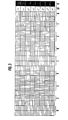
- Mixed colors are formed by nesting differently colored halftone dots, whereby the halftone dots of one color can also have different intensities. This is shown schematically in FIG. 3, in which, in addition to the four primary colors, the mixed colors blue (3), yellow-green (8), magenta (3) and orange (9) can be seen.
- White halftone dots (10) remain transparent, black halftone dots (11) are as little translucent as possible.
- the respective color intensity is determined by the color-generating area portion 12 of the respective raster element 13.
- the color-producing area portion 12 can contain raster elements 13 of all gradations between full color coverage with 100% coverage of homogeneous color and with a lack of color coverage.
- Colorful images are reproduced with the help of four partial images, which generate the primary colors blue-violet / green / yellow / red, with the aid of corresponding grid structures in one plane by projection with the aid of imaging optics.
- the grid structures can be designed as grid points for color matching.
- the technique according to the invention can also be used in the case of images by means of rastered optics such as lattice grids made of cylindrical lenses or cross louvres made of spherical lenses, for which a raster-like image decomposition is also required.
- the lattice constant for the relief lattice should be selected so that it is in the first diffraction diffracted light falls on the intermediate lens areas of the lenticular screen.
- the number of basic colors can be expanded beyond four. In most cases, the color rendering with four primary colors is quite satisfactory.
- White image areas are formed at grid-free image areas or at image areas with structures that only have a relatively small diffraction effect.
- the color black which in practice is often approximated by deep dark brown or deep dark violet, is based on strongly structured image areas that do not show a pronounced color effect. For example, very deep browns or blues occur in relief gratings in photoresists with a rectangular cross section at grating depths between 0.5 ⁇ m and about 1 ⁇ m.
- the relief structure is first produced in photoresist layers.
- a nickel matrix is removed from the relief grids in the photoresist layers and is used to emboss a thermoplastic film made of, for example, polyvinyl chloride. If the refractive index of the photoresist layer and the refractive cortex of the thermoplastic film are equal, for example 1.5, there is no color distortion on the embossed images. If there are differences in the refractive indices, the relief depth in the photoresist layer must be set so that the embossed image correctly reflects the desired projection colors . A measure of the depth adjustment is the optical path length difference d given by the grating depth.
- n 1 - n 2 refractive index of the lattice material
- n 2 refractive index of the outer medium
- the four primary colors blue-violet, green, yellow and red are obtained with optical path length differences of approximately 0.3 / 1.2 / 0.6 / 0.8 ⁇ m, this corresponds to relief depths in the photoresist between approximately 0.6 ⁇ m and 2.1. ⁇ m.
- Suitable methods for creating relief images are specified in patent application P 26 57 246.3.
- a photoresist layer on a glass or film carrier is exposed by color separation templates, in the sense of the present invention by one each for blue-violet, green, yellow and red, in such a way that relief structures of the desired grating depth have arisen at the relevant image points after development.
- White areas of the image are formed by overexposure or underexposure.
- Black image areas are formed by exposure using suitable templates to produce structures that are as panchromatic as possible to deflect the projection light. Special care is required to ensure that the originals are correctly placed on the photoresist layer, especially for rasterized images.
- the usual 120 rasters 120 raster periods / cm
- finer rasters up to halftone dots of 10 ⁇ m in diameter
- the color separation templates used are so ensure that they are only transparent in the areas to be imaged.
- the variant is possible that at least: white or more originals are transparent.
- Great care is required in terms of lattice exposure, in particular the contact between the photoresist and the lattice template.
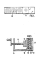
- the exposure is preferably carried out in a spindle press, shown schematically in FIG. 5, as an angular frame 14 with a light inlet opening 15 and a spindle 16.
- An arched spindle head 1 carries an elastic layer 18, which as the recording material from a support 19 and a film layer 2 against the grid template 21 presses.
- Focal length f 15 cm and through a blue glass filter with maximum transmission of 75% of the light intensity at 400 nm wavelength.
- the original is coated with a thin electrically conductive layer on which a metal coating is deposited. Then the original and the metal coating, whose contact surface with the original represents the negative relief image of the original, are separated from one another.
- a deformable material from which the information carrier is produced for example polyvinyl chloride, is embossed with the metal die thus produced in a manner known per se under pressure and under mostly temperature-related viscosity reduction.
- An approximately 2.5 pm thick layer of positive photoresist is applied to a bare transparent polyester film by spinning and drying. This layer is then brought under pressure into contact with a grid of 600 lines / mm made of metal webs on a glass plate and irradiated with actinic light with an energy of 280 mWs / cm 2 . This light energy is required for the grid-shaped exposure of the photoresist layer up to the polyester carrier.
- the first order of colors is due to increasing grating depths in the recording layer, while the reversal of the color sequence is the result of decreasing grating depths due to overexposure of the layer.
- the different color separation templates are placed one after the other with a grid pattern corresponding to a 120 grid in contact arrangement, and the exposure time is different depending on the desired projection color.
- the color separation templates are only transparent at the locations of the desired projection colors and at the white image areas.
- the registration of the color separation templates on the recording layer is done with the help of register marks under yellow safety light under a microscope.
- the black separation template contains a grid pattern of approx.
- the light energies for the exposure through the color separation templates were set at 105/125/140/205 mWs / cm 2 .
- the developed relief image was then evaporated with a thin copper layer on which nickel was electroplated.
- a polyvinyl chloride film was embossed in a press at approx. 130 C using the nickel die produced.
- the relief image created in the polyvinyl chloride film by a single embossing produced a colored image when projected in the undiffracted beam path, which largely resembled the projection image from the original relief image.
Abstract
Die Erfindung betrifft das Original eines Informationsträgers, der aus einer auf einem Trägermaterial aufgebrachten Aufzeichnungsschicht besteht. Auf der Aufzeichnungsschicht befinden sich zumindest vier Relief-Teilbilder, denen ein Reliefgitter mit unterschiedlichen Gittertiefen in den Bereichen der einzelnen Relief-Teilbilder überlagert ist.The invention relates to the original of an information carrier, which consists of a recording layer applied to a carrier material. At least four relief partial images are located on the recording layer, on which a relief grid with different grid depths is superimposed in the areas of the individual relief partial images.
Bei dem Verfahren zum Herstellen des Originals wird die Aufzeichnungsschicht durch getrennte Farbauszugsvorlagen für violett-bleue, grüne, gelbe und rote Projektionsfarben hindurch informationsmäßig belichtet, die in den Bereichen der jeweiligen Projektionsfarbe transparent sind und deren Teilbilder-Bereiche der Projektionsfarben überlappungsfrei aneinander grenzen.
Description
Die Erfindung betrifft ein Original eines. Informationsträgers, bestehend aus einer auf einem Trägermaterial aufgebrachten Aufzeichnungsschicht, die ein die Information wiedergebendes Reliefbild enthält, wobei sich das Reliefbild aus mehreren überlappungsfrei aneinander grenzenden Relief-Teilbildern in einer Ebene zusammensetzt, denen ein Reliefgitter mit unterschiedlichen Gittertiefen in den Bereichen der einzelnen Relief-Teilbilder überlagert ist, sowie ein Verfahren zum Herstellen des Originals.The invention relates to an original one. Information carrier, consisting of a recording layer applied to a carrier material, which contains a relief image representing the information, the relief image being composed of a plurality of relief partial images adjoining one another without overlap in one plane, to which a relief grid with different lattice depths in the areas of the individual relief partial images is superimposed, and a method for producing the original.
Mit der aus der Zeitschrift Laser u. Opto-Elektronik Nr. 3/1976, Seiten 16/17 bekannten ZOD (Zero-Order-Dif- fraction)-Technik werden gittermäßig gerasterte Bilder erzeugt. Von den Reliefbildern, die beispielsweise drei Grundfarbengittermustern in gelb, magenta und cyan in drei Fotolackschichten entsprechen, werden drei Nickelmatrizen hergestellt, mit denen farblose thermoplastische Folien aus beispielsweise Polyvinylchlorid geprägt werden. Diese Folien werden machanisch überlagert und bei der Projektion mit konventionellen Projektoren werden von den farblosen Reliefbildern farbige Projektionsbilder erhalten. Die gitterförmige Rasterung erfolgt mit Reliefgittern von rechteckförmigem Querschnitt, wobei die Gitterperiode etwa 1,5 Zum beträgt. Für jeden Farbauszug in magenta, gelb und cyan werden getrennt je eine Nickelmatrize mit unterschiedlicher Relieftiefe erstellt, mit der die getrennten Prägebilder erzeugt werden. Die Relieftiefen sind unterschiedlich, wobei die Relieftiefe beim Cyanauszug am größten und beim Gelbauszug am kleinsten ist. Diese Farbauszugsbilder sind gerastert. Die Prägebilder werden zu einem dreischichtigen Reliefbild überlagert, von dem farbige Bilder projiziert werden können. Die beschriebene Technik ergibt sehr helle Farbbilder großer Auflösung. Die Reliefbilder können durch Prägen relativ billig und schnell vervielfältigt werden.With the from the magazine Laser u. Opto-Electronics No. 3/1976,
Ein Nachteil, der die Einführung dieser Technik erschwert, ist der aufwendige Herstellungsprozeß mit drei vollständig getrennten Arbeitsgängen zur Herstellung der einzelnen, den Farbauszügen entsprechenden geprägten Reliefbilder. Ein weiterer Nachteil ist das paßgerechte Zusammensetzen der drei getrennten Reliefbilder zu dem für die farbige Projektion erforderlichen Duplikatbild.A disadvantage that complicates the introduction of this technique is the complex manufacturing process with three completely separate work steps for producing the individual embossed relief images corresponding to the color separations. Another disadvantage is that the three separate relief images are put together to fit the duplicate image required for the color projection.
In der deutschen Patentanmeldung P 26 57 246.3 ist bereits eine Lösung angegeben, die diese Nachteile vermeidet. Danach setzt sich das Reliefbild aus den den einzelnen Farbauszügen entsprechenden Relief-Teilbildern in der Weise zusammen, daß verschiedenfarbige Bereiche, das können bei gerasterten Bildern auch Rasterpunkte sein, in einer Ebene angeordnet sind, wobei sich die verschiedenfarbigen Bereiche nicht überschneiden, sondern höchstens berühren. Derartige Reliefbilder eignen sich sehr gut zur Darstellung von flächenhaften mehrfarbigen Vorlagen, wie graphische Darstellungen, in Form von Reliefgitterstrukturen in einer Ebene.In the German patent application P 26 57 246.3 a solution is already given which avoids these disadvantages. The relief image is then composed of the relief partial images corresponding to the individual color separations in such a way that differently colored areas, which in the case of rasterized images can also be halftone dots, are arranged in one plane, the differently colored areas not overlapping but at most touching. Relief images of this type are very well suited for displaying flat, multicolored templates, such as graphic representations, in the form of relief grid structures in one plane.
Die in der deutschen Patentanmeldung P 26 57 246.3 offenbarte Erfindung arbeitet mit drei Grundfarben, die im allgemeine nicht zur vorlagenähnlichen Darstellung von bunten Vorlagen mit Mischfarben, beispielsweise von bunten Landschaftsbildern, ausreichen.The invention disclosed in German patent application P 26 57 246.3 works with three basic colors, which are generally not for the presentation of colorful templates similar to a template with mixed colors, for example of colorful landscapes, are sufficient.
Aufgabe der Erfindung ist es, ein Original eines Informationsträgers zu schaffen, der für die Wiedergabe von beliebigen, kompletten Farbbildern, unter Einschluß von Mischfarben, geeignet ist.The object of the invention is to provide an original of an information carrier which is suitable for the reproduction of any, complete color images, including mixed colors.
Diese Aufgabe wird erfindungsgemäß dadurch-gelöst, daß zumindest vier Relief-Teilbilder mit unterschiedlich tiefen Gitterstrukturen in einer Ebene entsprechend den Projektionsfarben gelb, rot, blau-violett, grün vorgesehen sind.This object is achieved according to the invention in that at least four relief partial images with lattice structures of different depths are provided in one plane corresponding to the projection colors yellow, red, blue-violet, green.
Die weitere Ausgestaltung des Originals sowie das Verfahren zum Herstellen eines Originals sind aus den kennzeichnenden Merkmalen der Patentansprüche 2 bis 10 ersichtlich.The further design of the original and the method for producing an original can be seen from the characterizing features of
Mit der Erfindung wird der Vorteil erzielt, daß durch die Belichtung der Aufzeichnungsschicht mit den Farbauszugsvorlagen eines Farbsystems aus nur vier Grundfarben, nämlich blau-violett, grün, gelb und rot, ein Reliefbild eines Originals erhalten wird, mit dem infolge der in einer einzigen Ebene befindlichen Gitterstrukturen mit einer einzigen Prägung diese vier Grundfarben und sämtliche daraus durch Verschachtelung erzielbaren Mischfarben für ein komplettes Farbbild erhalten werden können.With the invention, the advantage is achieved that by the exposure of the recording layer with the color separation templates of a color system from only four basic colors, namely blue-violet, green, yellow and red, a relief image of an original is obtained, with which, as a result, in a single plane existing lattice structures with a single embossing these four basic colors and all the mixed colors that can be obtained therefrom by nesting can be obtained for a complete color image.
Die Erfindung wird im folgenden anhand der Zeichnungen näher beschrieben.The invention is described below with reference to the drawings.
Es zeigen:
- Fig. 1 in schematischer, perspektivischer Ansicht die Bildung von Mischfarben durch subtraktive Überlagerung, wie im Stand der Technik bekannt,
- Fig. 2 schematisch in perspektivischer Darstellung die Bildung von Mischfarben durch additive Zusammensetzung, wie im Stand der Technik bekannt,
- Fig. 3 schematisch die Verschachtelung der Grundfarben bei der Herstellung eines Originals,
- Fig. 4 eine Anzahl von Rasterelementen mit schematisch dargestellter abgestufter Farbintensität nach Fig. 3, und
- Fig. 5 eine Vorrichtung zur Rasterung der Aufzeichnungsschicht.
- 1 is a schematic, perspective view of the formation of mixed colors by subtractive superimposition, as is known in the prior art,
- 2 schematically shows a perspective representation of the formation of mixed colors by additive composition, as is known in the prior art,
- 3 schematically shows the nesting of the primary colors in the production of an original,
- FIG. 4 shows a number of raster elements with a schematically illustrated graded color intensity according to FIG. 3, and
- 5 shows a device for screening the recording layer.
Im Stand der Technik nach dem ZOD-Verfahren erfolgt die Bildung einzelner Farben nach einem subtraktiven Verfahren, das anhand von Figur 1 erläutert wird. Von den Grundfarben gelb (1), cyan (2) und magenta (3) ausgehend werden Mischfarben wie grün (4) durch Überlagerung von gelben und cyanfarbigen Bereichen gebildet, die als entsprechende Gitterstrukturen auf verschiedene Folien geprägt werden. Entsprechend werden rot (5) durch Überlagerung.von gelb (11 und magenta (3) und violett (6) durch Überlagerung von ![]()
![]()
Das gleichfalls bekannte additive Verfahren geht von den Grundfarben violett (6), grün (4) und rot (5) aus. Gelb (1) wird beispielsweise aus grünem (4) und rotem (5) Licht gebildet. Entsprechend werden blau (2) und magenta (3) gebildet. Bei Kopiermaterialien, die nach dem additiven Farbsystem konzipiert sind, besteht ein Bildelement, beispielsweise ein Rasterpunkt, aus je einem grünen (4), roten (5) und violetten Farbfilterbereich (6), wie Fig. 2 zeigt. Die Farbfilterbereiche sind ohne Überlappungen nebeneinander in einer Ebene angeordnet. Werden alle drei Farbfilterbereiche durchstrahlt, so erscheint der Rasterpunkt weiß, werden nur ein oder zwei Farbfilterbereiche durchstrahlt, so ist der projizierte Rasterpunkt farbig entsprechend dem einen oder den beiden durchstrahlten Farbfilterbereichen.The also known additive process is based on the basic colors violet (6), green (4) and red (5). Yellow (1) is formed, for example, from green (4) and red (5) light. Blue (2) and magenta (3) are formed accordingly. In the case of copying materials which are designed according to the additive color system, a picture element, for example a halftone dot, consists of a green (4), red (5) and violet color filter area (6), as shown in FIG. 2. The color filter areas are arranged next to one another in one plane without overlaps. If all three color filter areas are irradiated, the halftone dot appears white; if only one or two color filter areas are irradiated, the projected halftone dot is colored in accordance with one or the two irradiated color filter areas.
Der nicht erwünschte Farbanteil kann durch Abdecken des betreffenden Farbfilterbereiches, z.B. durch entwickelte Silberkörner in einer fotografischen Schicht, nicht zur Wirkung gelangen. Es ist offensichtlich, daß die Helligkeit von projizierten Farbbildern nach der additiven Technik nicht so groß ist wie die von Farbbildern nach der subtraktiven Technik, da im ersten Fall nur zwei Teilbereiche des Rasterpunktes durchstrahlt werden, während im zweiten Fall alle drei Teilbereiche durchstrahlt werden. Ein weiterer Nachteil der beschriebenen additiven Technik ist die Unterteilung der Bildelemente, in der Regel sind das Rasterpunkte, in kleinere Flächen, weil dadurch die Anforderungen bezüglich der Positioniergenauigkeit für Farbauszugsvorlagen bei Belichtungen der Fotolackschicht durch verschiedene Farbauszugsvorlagen merklich ansteigen.The undesired color component cannot be effective by covering the relevant color filter area, for example by developing silver grains in a photographic layer. It is obvious that the brightness of projected color images using the additive technique is not as great as that of color images using the subtractive technique, since in the first case only two partial areas of the halftone dot are irradiated, while in the second case all three partial areas are irradiated. Another disadvantage of the additive technique described is the division of the Image elements, usually raster dots, in smaller areas, because this increases the requirements regarding the positioning accuracy for color separation templates when exposing the photoresist layer through different color separation templates.
Das erfindungsgemäße Farbsystem ergibt genauso helle Projektionsbilder wie das subtraktive Farbsystem und vermeidet die Schwierigkeiten in bezug auf die Positioniergenauigkeit, wie sie beim additiven Verfahren auftreten. Es bietet weiterhin den Vorteil der kompletten Bildspeicherung in Form von Reliefgitterstrukturen in einer Ebene.The color system according to the invention produces projection images that are as bright as the subtractive color system and avoids the difficulties with regard to the positioning accuracy that occur with the additive method. It also offers the advantage of complete image storage in the form of relief grid structures on one level.
Aus der Beschreibung des additiven und subtraktiven Farbsystems mit je drei Grundfarben ist ersichtlich, daß die Schwierigkeit in der Erzeugung der Mischfarben besteht. Um diese Schwierigkeit zu vermeiden, werden nach der Erfindung neben schwarz und weiß vier Grundfarben verwendet. Die Grund. farben sind blau-violett (430 - 480 nm), grün (510 - 540 nm) gelb (570 - 600 nm) und rot (610 - 650 nm). Diese vier Grund farben überdecken den sichtbaren Spektralbereich in einer Weise, bei der die Lücken zwischen den einzelnen Grundfarben bereichen viel geringer sind als bei nur drei Grundfarben, deshalb sind beispielsweise für die Darstellung von magenta' aus den zwei Grundf arben rot und blau-violett, nur Spektralbereiche dieser beiden Grundfarben erforderlich, die im Vergleich zu einem Farbsystem mit drei Grundfarben geringeren spektralen Abstand voneinander aufweisen.From the description of the additive and subtractive color system, each with three primary colors, it can be seen that the difficulty lies in the generation of the mixed colors. In order to avoid this difficulty, four basic colors are used in addition to black and white according to the invention. The reason. colors are blue-violet (430 - 480 nm), green (510 - 540 nm) yellow (570 - 600 nm) and red (610 - 650 nm). These four primary colors cover the visible spectral range in such a way that the gaps between the individual primary colors are much smaller than with only three primary colors. For example, for the display of magenta 'from the two primary colors, red and blue-violet, only spectral ranges of these two primary colors are required which have a smaller spectral distance from one another in comparison to a color system with three primary colors.
Das wiederzugebende Farbbild wird gerastert, d.h. die Bildfläche wird in kleine Teilbereiche zerlegt. Jeder Rasterpunktbereich, der nicht schwarz oder weiß'ist, enthält nur eine der vier Grundfarben. Mischfarben werden durch Verschachtelung von verschiedenfarbigen Rasterpunkten gebildet, wobei noch die Rasterpunkte einer Farbe unterschiedliche Intensität besitzen können. In Figur 3 ist dies schematisch dargestellt, in der neben den vier Grundfarben die Mischfarben blau (3), gelb-grün (8), magenta (3) und orange (9) zu sehen sind. Weiße Rasterpunkte (10) bleiben transparent, schwarze Rasterpunkte (11) sind möglichst wenig lichtdurchlässig.The color image to be reproduced is rasterized, ie the image area is broken down into small sections. Each halftone dot area that is not black or white contains only one of the four primary colors. Mixed colors are formed by nesting differently colored halftone dots, whereby the halftone dots of one color can also have different intensities. This is shown schematically in FIG. 3, in which, in addition to the four primary colors, the mixed colors blue (3), yellow-green (8), magenta (3) and orange (9) can be seen. White halftone dots (10) remain transparent, black halftone dots (11) are as little translucent as possible.
Wie aus Fig. 4 ersichtlich ist, wird die jeweilige Farbintensität durch den Farbe erzeugenden Flächenanteil 12 des jeweiligen Rasterelementes 13 bestimmt. Der Farbe erzeugende Flächenanteil 12 kann Rasterelemente 13 aller Abstufungen zwischen voller Farbbedeckung mit 100 % Belegung an homogener Farbe und mit fehlender Farbbedeckung enthalten.As can be seen from FIG. 4, the respective color intensity is determined by the color-generating
Die Wiedergabe von bunten Bildern mit Hilfe von vier, die Grundfarben blau-violett/grün/gelb/rot erzeugenden Teilbildern mit Hilfe von entsprechenden Gitterstrukturen in einer Ebene erfolgt durch Projektion mit Hilfe einer Abbildungsoptik. Zur Farbanpassung können die Gitterstrukturen dabei als Rasterpunkte ausgebildet sein. Die erfindungsgemäße Technik ist auch bei Abbildungen durch gerasterte Optiken wie Gitterraster aus Zylinderlinsen oder Kreuzraster aus sphärischen Linsen anwendbar, wofür gleichfalls eine rasterartige Bildzerlegung erforderlich ist. Dabei ist die Gitterkonstante für das Reliefgitter so zu wählen, daß das in der ersten Beugungscrdnung abgelenkte Licht auf die Zwischenlinsenbereiche des Linsenrasters fällt.Colorful images are reproduced with the help of four partial images, which generate the primary colors blue-violet / green / yellow / red, with the aid of corresponding grid structures in one plane by projection with the aid of imaging optics. The grid structures can be designed as grid points for color matching. The technique according to the invention can also be used in the case of images by means of rastered optics such as lattice grids made of cylindrical lenses or cross louvres made of spherical lenses, for which a raster-like image decomposition is also required. The lattice constant for the relief lattice should be selected so that it is in the first diffraction diffracted light falls on the intermediate lens areas of the lenticular screen.
Für feinere Farbabstufungen kann die Zahl der Grundfarben über vier hinaus erweitert werden. In den meisten Fällen ist die Farbwiedergabe mit vier Grundfarben recht befriedigend. Weiße Bildbereiche werden an gitterfreien Bildstellen gebildet oder an Bildstellen mit Strukturen, die nur einen relativ geringen Beugungseffekt bewirken. Die Farbe schwarz, die in der Praxis oft durch tiefes Dunkelbraun oder tiefes Dunkelviolett angenähert wird, geht von stark strukturierten Bildstellen aus, die keinen ausgeprägten Farbeffekt zeigen. Beispielsweise treten bei Reliefgittern in Fotolacken mit rechteckförmigem Querschnitt bei Gittertiefen zwischen 0,5 µm und etwa 1 µm sehr dunkle Brauntöne oder Blautöne auf.For finer color gradations, the number of basic colors can be expanded beyond four. In most cases, the color rendering with four primary colors is quite satisfactory. White image areas are formed at grid-free image areas or at image areas with structures that only have a relatively small diffraction effect. The color black, which in practice is often approximated by deep dark brown or deep dark violet, is based on strongly structured image areas that do not show a pronounced color effect. For example, very deep browns or blues occur in relief gratings in photoresists with a rectangular cross section at grating depths between 0.5 µm and about 1 µm.
Beim bevorzugten Herstellungsprozeß derartiger Reliefgitterbilder wird zuerst die Reliefstruktur in Fotolackschichten erzeugt. Von den Reliefgittern in den Fotolackschichten wird eine Nickelmatrize abgenommen, mit der eine thermoplastische Folie aus beispielsweise Polyvinylchlorid geprägt wird. Wenn der Brechungsindex der Fotolackschicht und der Brechungsinde der thermoplastischen Folie gleich sind, beispielsweise 1,5 betragen, tritt an den Prägebildern keine Farbverzerrung auf Bei Unterschieden in den Brechungsindizes muß die Relieftief in der Fotolackschicht so eingestellt werden, daß das Prägebild die gewünschten Projektionsfarben richtig wiedergibt. Ein Maß für die Tiefenanpassung ist der durch die Gittertiefe vorgegebene optische Weglängenunterschied d . (n1 - n 2) mit d = Relieftiefe, n1 = Brechungsindex des Gittermaterials und n2 = Brechungsindex des äußeren Mediums, bei Luft ist n2 = 1 in der Praxis. Es werden die vier Grundfarben blau-violett, grün, gelb und rot bei optischen Weglängenunterschieden von etwa 0,3/1,2/0,6/0,8 µm erhalten, dies entspricht Relief tiefen im Fotolack zwischen etwa 0,6 um und 2,1. µm.In the preferred production process for such relief grid images, the relief structure is first produced in photoresist layers. A nickel matrix is removed from the relief grids in the photoresist layers and is used to emboss a thermoplastic film made of, for example, polyvinyl chloride. If the refractive index of the photoresist layer and the refractive cortex of the thermoplastic film are equal, for example 1.5, there is no color distortion on the embossed images.If there are differences in the refractive indices, the relief depth in the photoresist layer must be set so that the embossed image correctly reflects the desired projection colors . A measure of the depth adjustment is the optical path length difference d given by the grating depth. (n 1 - n 2 ) with d = relief depth, n 1 = refractive index of the lattice material and n 2 = refractive index of the outer medium, with air n 2 = 1 in practice. The four primary colors blue-violet, green, yellow and red are obtained with optical path length differences of approximately 0.3 / 1.2 / 0.6 / 0.8 µm, this corresponds to relief depths in the photoresist between approximately 0.6 µm and 2.1. µm.
Geeignete Verfahren zur Reliefbilderzeugung sind in der Patentanmeldung P 26 57 246.3 angegeben. Eine Fotolackschicht auf einem Glas- oder Filmträger wird durch Farbauszugsvorlagen, im Sinne der vorliegenden Erfindung durch je eine für blau-violett, grün, gelb und rot, so belichtet, daß nach der Entwicklung an den betreffenden Bildstellen Reliefstrukturen der gewünschten Gittertiefe entstanden sind. Dabei werden weiße Bildstellen durch Über- oder Unterbelichtung gebildet. Schwarze Bildstellen werden durch Belichtung durch geeignete Vorlagen zur Erzeugung von das Projektionslicht möglichst panchromatisch ablenkenden Strukturen gebildet. Besondere Sorgfalt erfordert das jeweilige paßgerechte Auflegen der Vorlagen auf die Fotolackschicht, besonders bei gerasterten Bildern. Je nach angestrebter Bildqualität werden übliche 120er Raster (120 Rasterperioden/cm) oder feinere Raster bis zu Rasterpunkten von 10 µm Durchmesser verwendet, die Positioniergenauigkeiten zwischen 10 um und 1 µm erfordern. Die benutzten Farbauszugsvorlagen einschließlich der Schwarzauszugsvorlage sind so beschaffen, daß sie nur an den jeweils zu bebildernde Stellen transparent sind. Für weiße Bildstellen ist die Variante möglich, daß an diesen Stellen mindestens :wei oder mehr Vorlagen trarsparent sind. Große Sorgfalt erfordert die gittermäßi Belichtung, insbesondere der Kontakt von Fotolackschcht und Gittervorlage. Dies gilt vor allem für Gittervoragen mit großen Liniendichten um 600 Linien/mm, die beispielsweise aus Metallstegen auf Glasplatten bestehen, bei denen der Andruck in üblichen Vakuumkopierrahmen nict zuverlässig ausreient. Deshalb erfolgt die Belichtungvorzugsweise in einer in Fig. 5 schematisch dargestellen Spindelpresse as einem Winkelrahmen 14 mit einer Lchteintrittsöffnun 15 sowie einer Spindel 16. Ein gewölter Spindelkopf 1 trägt eine elastische Schicht 18, die as Aufzeichnungsaterial aus einem Träger 19 und einer ftolackschicht 2 gegen die Gittervorlage 21 anpreßt.Suitable methods for creating relief images are specified in patent application P 26 57 246.3. A photoresist layer on a glass or film carrier is exposed by color separation templates, in the sense of the present invention by one each for blue-violet, green, yellow and red, in such a way that relief structures of the desired grating depth have arisen at the relevant image points after development. White areas of the image are formed by overexposure or underexposure. Black image areas are formed by exposure using suitable templates to produce structures that are as panchromatic as possible to deflect the projection light. Special care is required to ensure that the originals are correctly placed on the photoresist layer, especially for rasterized images. Depending on the desired image quality, the usual 120 rasters (120 raster periods / cm) or finer rasters up to halftone dots of 10 µm in diameter are used, which require positioning accuracies between 10 µm and 1 µm. The color separation templates used, including the black separation template, are so ensure that they are only transparent in the areas to be imaged. For white image areas, the variant is possible that at least: white or more originals are transparent. Great care is required in terms of lattice exposure, in particular the contact between the photoresist and the lattice template. This applies above all to grid templates with large line densities of around 600 lines / mm, which consist, for example, of metal webs on glass plates, for which the pressure in conventional vacuum copying frames is not reliably sufficient. For this reason, the exposure is preferably carried out in a spindle press, shown schematically in FIG. 5, as an

Eine etwa 2.5 pm dicke Schicht aus positiv arbeitendem Fotolack wird durch Schleudern und Trocknen auf einer blanken transparenten Polyesterfolie aufgebracht. Anschließend wird diese Schicht unter Druck in Kontakt mit einem Gitter von 600 Linien/mm aus Metallstegen auf einer Glasplatte gebracht und mit aktinischem Licht mit einer Energie von 280 mWs/cm2 bestrahlt. Diese Lichtenergie wird zur gitterförmigen Ausbelichtung der Fotolackschicht bis zum Polyesterträger benötigt.An approximately 2.5 pm thick layer of positive photoresist is applied to a bare transparent polyester film by spinning and drying. This layer is then brought under pressure into contact with a grid of 600 lines / mm made of metal webs on a glass plate and irradiated with actinic light with an energy of 280 mWs / cm 2 . This light energy is required for the grid-shaped exposure of the photoresist layer up to the polyester carrier.
In Vorversuchen wurde festgestellt, daß bei gleicher Intensität und zunehmenden Belichtungszeiten Projektionsfarben in der Reihenfolge braungelb/magenta/blau-violett/gelb/rot/ magenta/cyan/blaugrün/grün/gelbgrün/magenta auftreten, und bei weiter zunehmenden Belichtungszeiten die Projektionsfarben in umgekehrter Reihenfolge erscheinen.In preliminary experiments it was found that with the same intensity and increasing exposure times, projection colors occur in the order brown-yellow / magenta / blue-violet / yellow / red / magenta / cyan / blue-green / green / yellow-green / magenta, and with increasing exposure times, the projection colors appear in reverse order.
Die erste Reihenfolge der Farben ist auf zunehmende Gittertiefen in der Aufzeichnungsschicht zurückzuführen, während die Umkehr der Farbenreihe die Folge von abnehmenden Gittertiefen durch Überbelichtung der Schicht ist.The first order of colors is due to increasing grating depths in the recording layer, while the reversal of the color sequence is the result of decreasing grating depths due to overexposure of the layer.
Nach der Ausbelichtung werden nacheinander die verschiedenen Farbauszugsvorlagen mit einem Rastermuster entsprechend einem 120er Raster in Kontaktanordnung aufgelegt, und es wird je nach angestrebter Projektionsfarbe verschieden lang belichtet. Die Farbauszugsvorlagen sind nur an den Stellen der jeweils gewünschten Projektionsfarben und an den weißen Bildstellen transparent. Die paßgerechte Auflage der Farbauszugsvorlagen auf der Aufzeichnungsschicht erfolgt mit Hilfe von Paßkreuzen bei gelbem Sicherheitslicht unter einem Mikroskop. Es werden für die Projektionsfarben grün/rot/gelb/blau-violett beispiels weise 110/130/150/220 mWs/cm2 eingestrahlt. Diese Lichtenergien wurden in Vorversuchen ermittelt. Die Schwarzauszugsvorlage enthält in den betreffenden Bildbereichen ein Gittermuster von ca. 300 Linien/mm, das zur bereits aufbelichteten Gitterstruktur senkrecht oder auch geneigt orientiert ist; es werden etwa 150 mWs/cm2 eingestrahlt. Die erhaltene Projektionsfarbe ist ein dunkles Graubraun. Entwickelt wird mit wäßrigem alkalischem Entwickler. Bei der Projektion des Reliefbildes mit einer Optik der Lichtstärke 1 : 2,8 wird ein buntes, der Originalvorlage ähnliches Bild mit Mischfarben in entsprechend abgestuften Farbintensitäten erhalten. Weiße Bildstellen werden weiß wiedergegeben, schwarze.Bildstellen der Originalvorlage dunkelbraun.After the exposure, the different color separation templates are placed one after the other with a grid pattern corresponding to a 120 grid in contact arrangement, and the exposure time is different depending on the desired projection color. The color separation templates are only transparent at the locations of the desired projection colors and at the white image areas. The registration of the color separation templates on the recording layer is done with the help of register marks under yellow safety light under a microscope. For the projection colors green / red / yellow / blue-violet, for example, 110/130/150/220 mWs / cm 2 are irradiated. These light energies were determined in preliminary tests. The black separation template contains a grid pattern of approx. 300 lines / mm in the relevant image areas, which is oriented perpendicularly or also inclined to the grid structure already exposed; about 150 mWs / cm 2 are irradiated. The projection color obtained is a dark gray-brown. It is developed with an aqueous alkaline developer. When the relief image is projected with optics with a light intensity of 1: 2.8, a colorful image, similar to the original, with mixed colors in correspondingly graduated color intensities is obtained. White image areas are reproduced in white, black image areas in the original artwork are dark brown.
In einem zweiten Versuch wurden die Lichtenergien für die Belichtung durch die Farbauszugsvorlagen hindurch auf 105/125/140/205 mWs/cm2 festgelegt. Anschließend wurde das entwickelte Reliefbild mit einer dünnen Kupferschicht bedampft, auf der galvanisch Nickel abgeschieden wurde. Mit der hergestellten Nickelmatrize wurde bei ca. 130 C in einer Presse eine Polyvinylchloridfolie geprägt. Das durch eine einzige Prägung entstandene Reliefbild in der Polyvinylchloridfolie ergab bei der Projektion im ungebeugten Strahlengang ein farbiges Bild, das dem Projektionsbild vom Originalreliefbild weitgehend glich.In a second experiment, the light energies for the exposure through the color separation templates were set at 105/125/140/205 mWs / cm 2 . The developed relief image was then evaporated with a thin copper layer on which nickel was electroplated. A polyvinyl chloride film was embossed in a press at approx. 130 C using the nickel die produced. The relief image created in the polyvinyl chloride film by a single embossing produced a colored image when projected in the undiffracted beam path, which largely resembled the projection image from the original relief image.
Claims (10)
Applications Claiming Priority (2)
| Application Number | Priority Date | Filing Date | Title |
|---|---|---|---|
| DE2734581A DE2734581C2 (en) | 1977-08-01 | 1977-08-01 | Original of an information carrier and method for producing the original |
| DE2734581 | 1977-08-01 |
Publications (2)
| Publication Number | Publication Date |
|---|---|
| EP0000570A1 true EP0000570A1 (en) | 1979-02-07 |
| EP0000570B1 EP0000570B1 (en) | 1981-01-14 |
Family
ID=6015338
Family Applications (1)
| Application Number | Title | Priority Date | Filing Date |
|---|---|---|---|
| EP78100480A Expired EP0000570B1 (en) | 1977-08-01 | 1978-07-24 | Original of an optical information carrier and process for realising this original |
Country Status (7)
| Country | Link |
|---|---|
| US (1) | US4269915A (en) |
| EP (1) | EP0000570B1 (en) |
| JP (1) | JPS5436956A (en) |
| AT (1) | AT373698B (en) |
| CA (1) | CA1109313A (en) |
| DE (2) | DE2734581C2 (en) |
| IT (1) | IT7850547A0 (en) |
Cited By (1)
| Publication number | Priority date | Publication date | Assignee | Title |
|---|---|---|---|---|
| EP0006504A1 (en) * | 1978-06-16 | 1980-01-09 | Hoechst Aktiengesellschaft | Colour separation transparency and method for its preparation |
Families Citing this family (5)
| Publication number | Priority date | Publication date | Assignee | Title |
|---|---|---|---|---|
| DE2853953A1 (en) * | 1978-12-14 | 1980-07-03 | Hoechst Ag | IDENTIFICATION CARD |
| US4737448A (en) * | 1986-03-31 | 1988-04-12 | Xerox Corporation | Color images formed by multiple diffraction gratings |
| US5264880A (en) * | 1991-12-30 | 1993-11-23 | Xerox Corporation | Method and apparatus for projecting a color image |
| US5217832A (en) * | 1992-01-23 | 1993-06-08 | The Walt Disney Company | Permanent color transparencies on single substrates and methods for making the same |
| US5503902A (en) * | 1994-03-02 | 1996-04-02 | Applied Physics Research, L.P. | Light control material |
Citations (7)
| Publication number | Priority date | Publication date | Assignee | Title |
|---|---|---|---|---|
| GB189911466A (en) * | 1899-06-02 | 1900-04-28 | Thomas Thorp | Improvements in the Method of and Means for Rendering Photographic and other Pictures of Objects Visible in their Natural or in other Desired Colours. |
| DE140907C (en) * | 1899-03-07 | 1903-05-11 | ||
| GB190606825A (en) * | 1905-10-19 | 1906-09-27 | Herbert Eugene Ives | Improvements in Diffraction Colour Photographs and Mode of Making same |
| FR2299661A1 (en) * | 1975-02-03 | 1976-08-27 | Rca Corp | SUBTRACTIVE CHROMATIC FILTERING PROCESS AND APPARATUS |
| NL7700486A (en) * | 1976-01-19 | 1977-07-21 | Rca Corp | SUBTRACTIVE BREAKING LIGHT FILTER. |
| DE2703160A1 (en) * | 1976-01-27 | 1977-07-28 | Rca Corp | SAMPLE PHOTOGRAPH FOR THE MANUFACTURING OF SUBTRACTIVE DRAFTED COLOR FILTERS |
| DE2657246B1 (en) * | 1976-12-17 | 1978-02-23 | Hoechst Ag | Original of an information carrier, method for producing the original, method for producing a die for embossing the original and information carrier which is produced with the die |
Family Cites Families (10)
| Publication number | Priority date | Publication date | Assignee | Title |
|---|---|---|---|---|
| US2875047A (en) * | 1955-01-19 | 1959-02-24 | Oster Gerald | Photopolymerization with the formation of coherent plastic masses |
| US4006018A (en) * | 1968-05-10 | 1977-02-01 | Minnesota Mining And Manufacturing Company | Copying in color |
| US3672894A (en) * | 1970-04-27 | 1972-06-27 | Gen Electric | Method for making a composite back projection screen |
| US3834801A (en) * | 1970-09-21 | 1974-09-10 | Staley Mfg Co A E | Reflective elements |
| US3743507A (en) * | 1970-10-23 | 1973-07-03 | Rca Corp | Recording of a continuous tone focused image on a diffraction grating |
| US3763296A (en) * | 1971-03-05 | 1973-10-02 | American Charts Co | Method for making colored |
| US3732363A (en) * | 1971-08-16 | 1973-05-08 | Columbia Broadcasting Syst Inc | Information record utilizing diffraction grating and methods of recording and reproducing the information thereof |
| US3947105A (en) * | 1973-09-21 | 1976-03-30 | Technical Operations, Incorporated | Production of colored designs |
| US3993489A (en) * | 1973-11-14 | 1976-11-23 | Monsanto Company | Multi-color laminate of photopolymer that is image-wise hydroperoxidized |
| US4017158A (en) * | 1975-03-17 | 1977-04-12 | E. I. Du Pont De Nemours And Company | Spatial frequency carrier and process of preparing same |
-
1977
- 1977-08-01 DE DE2734581A patent/DE2734581C2/en not_active Expired
-
1978
- 1978-07-24 EP EP78100480A patent/EP0000570B1/en not_active Expired
- 1978-07-24 DE DE7878100480T patent/DE2860324D1/en not_active Expired
- 1978-07-27 US US05/928,700 patent/US4269915A/en not_active Expired - Lifetime
- 1978-07-28 CA CA308,354A patent/CA1109313A/en not_active Expired
- 1978-07-31 IT IT7850547A patent/IT7850547A0/en unknown
- 1978-07-31 AT AT0554578A patent/AT373698B/en not_active IP Right Cessation
- 1978-08-01 JP JP9408978A patent/JPS5436956A/en active Pending
Patent Citations (7)
| Publication number | Priority date | Publication date | Assignee | Title |
|---|---|---|---|---|
| DE140907C (en) * | 1899-03-07 | 1903-05-11 | ||
| GB189911466A (en) * | 1899-06-02 | 1900-04-28 | Thomas Thorp | Improvements in the Method of and Means for Rendering Photographic and other Pictures of Objects Visible in their Natural or in other Desired Colours. |
| GB190606825A (en) * | 1905-10-19 | 1906-09-27 | Herbert Eugene Ives | Improvements in Diffraction Colour Photographs and Mode of Making same |
| FR2299661A1 (en) * | 1975-02-03 | 1976-08-27 | Rca Corp | SUBTRACTIVE CHROMATIC FILTERING PROCESS AND APPARATUS |
| NL7700486A (en) * | 1976-01-19 | 1977-07-21 | Rca Corp | SUBTRACTIVE BREAKING LIGHT FILTER. |
| DE2703160A1 (en) * | 1976-01-27 | 1977-07-28 | Rca Corp | SAMPLE PHOTOGRAPH FOR THE MANUFACTURING OF SUBTRACTIVE DRAFTED COLOR FILTERS |
| DE2657246B1 (en) * | 1976-12-17 | 1978-02-23 | Hoechst Ag | Original of an information carrier, method for producing the original, method for producing a die for embossing the original and information carrier which is produced with the die |
Non-Patent Citations (5)
| Title |
|---|
| E.J. WALL: "The History of Three Color Photography", 1925, American Photographic Publishing Co. Boston, Seiten 670-681. * |
| J.S. FRIEDMAN: "History of color photography", second edition, 1968. The Focal Press London, Seiten 23-33. * |
| NATURWISSENSCHAFTEN, vol. 63, No. 4, April 1976, M.T. GALE et al.: "Farbenphotographie ohne Farbstoffe und Silber", Seiten 180-184. * |
| OPTICS COMMUNICATIONS, vol. 18, No. 3, August 1976, K. KNOP: "Color pictures using zero diffraction order of phase grating structures", Seiten 298-303. * |
| SMPTE JOURNAL, vol. 87, No. 1, Januar 1978. M.T. GALE et al: "Embossed relief images and their application for color motion pictures", Seiten 6-8. * |
Cited By (1)
| Publication number | Priority date | Publication date | Assignee | Title |
|---|---|---|---|---|
| EP0006504A1 (en) * | 1978-06-16 | 1980-01-09 | Hoechst Aktiengesellschaft | Colour separation transparency and method for its preparation |
Also Published As
| Publication number | Publication date |
|---|---|
| DE2734581C2 (en) | 1979-02-15 |
| US4269915A (en) | 1981-05-26 |
| JPS5436956A (en) | 1979-03-19 |
| CA1109313A (en) | 1981-09-22 |
| IT7850547A0 (en) | 1978-07-31 |
| EP0000570B1 (en) | 1981-01-14 |
| ATA554578A (en) | 1983-06-15 |
| AT373698B (en) | 1984-02-10 |
| DE2734581B1 (en) | 1978-06-01 |
| DE2860324D1 (en) | 1981-03-12 |
Similar Documents
| Publication | Publication Date | Title |
|---|---|---|
| DE2702015C2 (en) | Projection device for projecting a monochrome image with a phase diffraction grating structure | |
| DE2703160C3 (en) | Method for producing a master for a phase grating in a diffraction working subtractive color filter system | |
| DE2445114A1 (en) | MAKING COLORED DESIGNS | |
| DE1597521B2 (en) | Method for generating an integral image that provides a spatial image impression | |
| DE2152796A1 (en) | Modulated diffraction grating recording and method and recording material for making the same | |
| DE2657246C2 (en) | Original of an information carrier, method for producing the original, method for producing a die for embossing the original and information carrier which is produced with the die | |
| DE1937719A1 (en) | Stereoscopic photography | |
| EP0000570B1 (en) | Original of an optical information carrier and process for realising this original | |
| EP0000571B1 (en) | Process for the production of an original | |
| DE2901662A1 (en) | HALFTONE MICRO IMAGES AND METHOD OF MAKING THE SAME | |
| EP0002043B1 (en) | Process for the manufacture of an information carrier | |
| EP0006504B1 (en) | Colour separation transparency and method for its preparation | |
| DE69725781T2 (en) | Scanning of images | |
| DE2337819C3 (en) | Method of making a color stripe filter | |
| DE615499C (en) | Process for producing rasterless halftone reproductions, especially for security printing | |
| DE2421887C3 (en) | ||
| DE2125091C3 (en) | Method of making mating photocopying stencils | |
| CH643372A5 (en) | Method and device for producing a transparent image for preparing a pressing matrix for microimages | |
| AT156105B (en) | Method and apparatus for making lenticular color copies of lenticular color photographs. | |
| DE96773C (en) | ||
| DE2445465A1 (en) | Production of transparency copies - gradation controlled by raster device between original and copy | |
| DE658756C (en) | Process for the reproduction of color photographs on a layer support with an irregular three-color grid | |
| DE976397C (en) | Process for reproducing colored images by exposing partial color images onto multicolor material | |
| DE442031C (en) | Process to remove the colored dots and lines that appear when projecting a film bearing either colored printed pigments or covered with a grid of microscopic light-refracting elements with considerable enlargement, provided that the colors are symmetrically distributed | |
| DE583616C (en) | Production of multi-color photographic or cinematographic projection images |
Legal Events
| Date | Code | Title | Description |
|---|---|---|---|
| PUAI | Public reference made under article 153(3) epc to a published international application that has entered the european phase |
Free format text: ORIGINAL CODE: 0009012 |
|
| AK | Designated contracting states |
Designated state(s): BE CH DE FR GB NL |
|
| 17P | Request for examination filed | ||
| GRAA | (expected) grant |
Free format text: ORIGINAL CODE: 0009210 |
|
| AK | Designated contracting states |
Designated state(s): BE CH DE FR GB NL |
|
| REF | Corresponds to: |
Ref document number: 2860324 Country of ref document: DE Date of ref document: 19810312 |
|
| PGFP | Annual fee paid to national office [announced via postgrant information from national office to epo] |
Ref country code: BE Payment date: 19820630 Year of fee payment: 5 |
|
| PGFP | Annual fee paid to national office [announced via postgrant information from national office to epo] |
Ref country code: NL Payment date: 19820731 Year of fee payment: 5 |
|
| PGFP | Annual fee paid to national office [announced via postgrant information from national office to epo] |
Ref country code: CH Payment date: 19820930 Year of fee payment: 5 |
|
| PG25 | Lapsed in a contracting state [announced via postgrant information from national office to epo] |
Ref country code: BE Effective date: 19830724 |
|
| PG25 | Lapsed in a contracting state [announced via postgrant information from national office to epo] |
Ref country code: CH Effective date: 19830731 |
|
| PG25 | Lapsed in a contracting state [announced via postgrant information from national office to epo] |
Ref country code: NL Effective date: 19840201 |
|
| NLV4 | Nl: lapsed or anulled due to non-payment of the annual fee | ||
| REG | Reference to a national code |
Ref country code: CH Ref legal event code: PL |
|
| PGFP | Annual fee paid to national office [announced via postgrant information from national office to epo] |
Ref country code: FR Payment date: 19840621 Year of fee payment: 7 |
|
| PGFP | Annual fee paid to national office [announced via postgrant information from national office to epo] |
Ref country code: DE Payment date: 19840810 Year of fee payment: 7 |
|
| GBPC | Gb: european patent ceased through non-payment of renewal fee | ||
| PG25 | Lapsed in a contracting state [announced via postgrant information from national office to epo] |
Ref country code: FR Free format text: LAPSE BECAUSE OF NON-PAYMENT OF DUE FEES Effective date: 19860328 |
|
| PG25 | Lapsed in a contracting state [announced via postgrant information from national office to epo] |
Ref country code: DE Effective date: 19860402 |
|
| REG | Reference to a national code |
Ref country code: FR Ref legal event code: ST |
|
| PG25 | Lapsed in a contracting state [announced via postgrant information from national office to epo] |
Ref country code: GB Effective date: 19881117 |
|
| PLBE | No opposition filed within time limit |
Free format text: ORIGINAL CODE: 0009261 |
|
| STAA | Information on the status of an ep patent application or granted ep patent |
Free format text: STATUS: NO OPPOSITION FILED WITHIN TIME LIMIT |