EP0000467B1 - Spiked rakes with cleaning device for sewage treatment plants - Google Patents
Spiked rakes with cleaning device for sewage treatment plants Download PDFInfo
- Publication number
- EP0000467B1 EP0000467B1 EP78100039A EP78100039A EP0000467B1 EP 0000467 B1 EP0000467 B1 EP 0000467B1 EP 78100039 A EP78100039 A EP 78100039A EP 78100039 A EP78100039 A EP 78100039A EP 0000467 B1 EP0000467 B1 EP 0000467B1
- Authority
- EP
- European Patent Office
- Prior art keywords
- screen
- rake
- carriage
- pivot
- lever arrangement
- Prior art date
- Legal status (The legal status is an assumption and is not a legal conclusion. Google has not performed a legal analysis and makes no representation as to the accuracy of the status listed.)
- Expired
Links
- 238000004140 cleaning Methods 0.000 title claims description 7
- 239000010865 sewage Substances 0.000 title 1
- 230000005484 gravity Effects 0.000 claims description 6
- 238000004065 wastewater treatment Methods 0.000 claims description 2
- XLYOFNOQVPJJNP-UHFFFAOYSA-N water Substances O XLYOFNOQVPJJNP-UHFFFAOYSA-N 0.000 claims description 2
- 238000009434 installation Methods 0.000 claims 1
- 230000000284 resting effect Effects 0.000 claims 1
- 230000000717 retained effect Effects 0.000 claims 1
- 238000012216 screening Methods 0.000 description 7
- 239000000463 material Substances 0.000 description 5
- 230000002441 reversible effect Effects 0.000 description 4
- 239000006096 absorbing agent Substances 0.000 description 2
- 238000010276 construction Methods 0.000 description 2
- 230000035939 shock Effects 0.000 description 2
- 238000011144 upstream manufacturing Methods 0.000 description 2
- 230000002349 favourable effect Effects 0.000 description 1
- 238000000034 method Methods 0.000 description 1
- 230000001960 triggered effect Effects 0.000 description 1
Images

Classifications
-
- E—FIXED CONSTRUCTIONS
- E02—HYDRAULIC ENGINEERING; FOUNDATIONS; SOIL SHIFTING
- E02B—HYDRAULIC ENGINEERING
- E02B8/00—Details of barrages or weirs ; Energy dissipating devices carried by lock or dry-dock gates
- E02B8/02—Sediment base gates; Sand sluices; Structures for retaining arresting waterborne material
- E02B8/023—Arresting devices for waterborne materials
- E02B8/026—Cleaning devices
Definitions
- the invention relates to a bar rake with rake cleaner for wastewater treatment plants, with a carriage which can be moved up and down in parallel guides for rakes, a rake mounted on the carriage by means of swivel arms for cleaning the rake, which by means of the swivel arms between two positions, namely an engagement position on the rake and a release position can be pivoted at a distance from the rake, an articulated lever which has a pivot point on the carriage and a pivot point on the pivot arm and can assume an extended position and a bent position which are assigned to the two positions of the rake and with one in the movement path of the Articulated links arranged lower stop, through which the articulated lever can be moved from one position to the other at the end of the downward travel of the carriage, whereby the rake located in the release position when the carriage is traveling downward is pivoted into the engaged position by the change in position of the articulated lever and during the Au is kept in this direction.
- a rake with rake cleaner of this type is known from DE-PS 1 252 150.
- the articulated lever is arranged so that it is stretched during downward travel and the rake is locked in the release position and is bent by the fixed stop when the lower reversal point is reached, so that the rake can pivot into the engaged position.
- This rake is first swung in under its own weight.
- the traction means driving the car can be deflected on the car and anchored to the swivel arm of the rake, so that it pulls the rake against the rake with an additional force which corresponds to the weight of the car and the rake when the upward movement begins.
- the object of the invention is to improve a rake with rake cleaner of the type mentioned in such a way that the pivoting-in movement of the rake takes place with sufficient force and in a transverse movement to the rake running completely in the region of the lower reversal point, and that the upward movement only begins when the rake is completely swung in.
- This charge is achieved according to the invention in that the extended position of the articulated lever is assigned to the engagement position and the articulated position to the release position and the rake is positively supported against the carriage in the engaged position by the extended articulated lever.
- Swiveling of the rake which is completely independent of the weight of the rake and the trolley, is obtained if a drive is used which also exerts a driving force on the trolley when it descends.
- the downward travel of the car takes place under its own weight in accordance with the release of the traction means by the drive.
- the distance between the pivot point of the rake from the rake and the extension path of the articulated lever are dimensioned and coordinated with one another such that the pivoting-in movement of the rake with the downward movement of the carriage results in a substantially straight-line movement approximately transversely to the plane of the Computed overlay.
- an overload protection device which switches off the drive is provided for both drive directions of the carriage.
- the rake 1 consists of numerous parallel vertical bars, which are only anchored to the bottom 2 of the flow channel or the like and, moreover, freely project upwards without mutual connection or support.
- a carriage 4 with rollers 5 is guided up and down.
- the carriage 4 is connected by a link 6 to a rotating drive chain 7 which rotates at the bottom around a deflection roller 8 and at the top around a drive roller (not shown) driven by a reversible geared motor.
- the drive is reversible, so that the chain exerts a positive driving force on the carriage 4 both during the ascent and the descent.
- the carriage 4 extends over the entire width of the rake 1, and the guide 3 can consist of two guide rails on both sides of the carriage 4, or, if it is a relatively narrow rake 1, a centrally arranged rail with preferably Double T-shaped profile, which is surrounded by the carriage 4 in a U-shape.
Description
Die Erfindung betrifft einen Stabrechen mit Rechenreiniger für Abwasserbehandlungsanlagen, mit einem in zum Rechen parallelen Führungen auf- und abwärts verfahrbaren Wagen, einer am Wagen mittels Schwenkarmen gelagerten Harke für die Reinigung des Rechens, die mittels der Schwenkarme zwischen zwei Stellungen, nämlich einer Eingriffstellung am Rechen und einer Freigabestellung in Abstand vom Rechen schwenkbar ist, einem Knickhebel, der einen Anlenkpunkt am Wagen und einen Anlenkpunkt am Schwenkarm aufweist und eine gestreckte Lage und eine geknickte Lage einnehmen kann, die den beiden Stellungen der Harke zugeordnet sind und mit einem in der Bewegungsbahn des Knicklenkers angeordneten unteren Anschlag, durch den der Knickhebel am Ende der Abwärtsfahrt des Wagens aus der einen in die andere Lage bewegbar ist, wodurch die bei Abwärtsfahrt des Wagens in der Freigabestellung befindlichen Harke durch die Lageveränderung des Knickhebels in die Eingriffstellung eingeschwenkt und während der Aufwärtsfahrt in dieser gehalten wird.The invention relates to a bar rake with rake cleaner for wastewater treatment plants, with a carriage which can be moved up and down in parallel guides for rakes, a rake mounted on the carriage by means of swivel arms for cleaning the rake, which by means of the swivel arms between two positions, namely an engagement position on the rake and a release position can be pivoted at a distance from the rake, an articulated lever which has a pivot point on the carriage and a pivot point on the pivot arm and can assume an extended position and a bent position which are assigned to the two positions of the rake and with one in the movement path of the Articulated links arranged lower stop, through which the articulated lever can be moved from one position to the other at the end of the downward travel of the carriage, whereby the rake located in the release position when the carriage is traveling downward is pivoted into the engaged position by the change in position of the articulated lever and during the Au is kept in this direction.
Ein Rechen mit Rechenreiniger dieser Art ist aus DE-PS 1 252 150 bekannt. Der Knickhebel ist so angeordnet, daß er während der Abwärtsfahrt gestreckt ist und die Harke in der Freigabestellung arretiert und beim Erreichen des unteren Umkehrpunktes durch den ortsfesten Anschlag geknickt wird, so daß die Harke in die Eingriffsstellung einschwenken kann. Dieses Einschwenken der Harke erfolgt zunächst unter ihrem Eigengewicht. Zusätzlich kan das den Wagen antreibende Zugmittel am Wagen umgelenkt und am Schwenkarm der Harke verankert sein, so daß es bei beginnender Aufwärtsfahrt die Harke mit einer zusätzlichen Kraft, die dem Gewicht des Wagens und der Harke entspricht, gegen den Rechen zieht.A rake with rake cleaner of this type is known from DE-PS 1 252 150. The articulated lever is arranged so that it is stretched during downward travel and the rake is locked in the release position and is bent by the fixed stop when the lower reversal point is reached, so that the rake can pivot into the engaged position. This rake is first swung in under its own weight. In addition, the traction means driving the car can be deflected on the car and anchored to the swivel arm of the rake, so that it pulls the rake against the rake with an additional force which corresponds to the weight of the car and the rake when the upward movement begins.
Bei derartigen, durch ihr Eigengewicht gegen den Rechen einschwenkenden Reinigungsharken besteht die Gefahr, daß die Einschwenkkraft der Harke nicht ausreicht, um bereits am Rechen angeschwemmtes Gut vollständig zu erfassen. Es kann insbesondere vorkommen, daß die Harke erst im Verlauf ihrer Aufwärtsfahrt, wenn sich das volle Gewicht des Wagens über das Zugmittel auf die Harke auswirken kann, das Schwemmgut durchdringt, so daß am Fußpunkt des Rechens ungeräumte Reste des Schwemmgutes verbleiben.With such cleaning rakes which pivot in against the rake due to their own weight, there is a risk that the pivoting force of the rake is not sufficient to completely grasp goods which have already washed onto the rake. In particular, it may happen that the rake only penetrates the floating material during its upward travel, when the full weight of the car can affect the rake via the traction means, so that uncleaned remains of the floating material remain at the base of the rake.
Aufgabe der Erfindung ist es, einen Rechen mit Rechenreiniger der genannten Art so zu verbessern, daß die Einschwenkbewegung der Harke mit ausreichender Kraft und in einer vollständig im Bereich des unteren Umkehrpunktes ablaufenden Querbewegung zum Rechen stattfindet und daß die Aufwärtsfahrt erst dann beginnt, wenn die Harke vollständig eingeschwenkt ist.The object of the invention is to improve a rake with rake cleaner of the type mentioned in such a way that the pivoting-in movement of the rake takes place with sufficient force and in a transverse movement to the rake running completely in the region of the lower reversal point, and that the upward movement only begins when the rake is completely swung in.
Diese Aufgage wird erfindungsgemäß dadurch gelöst, daß die gestreckte Lage des Knickhebels der Eingriffstellung und die geknickte Lage der Freigabestellung zugeordnet ist und die Harke durch den gestreckten Knickhebel in der Eingriffstellung formschlüssig gegen den Wagen abgestützt ist.This charge is achieved according to the invention in that the extended position of the articulated lever is assigned to the engagement position and the articulated position to the release position and the rake is positively supported against the carriage in the engaged position by the extended articulated lever.
Hierdurch wird der Vorteil erzielt, daß der Knickhebel die Harke nicht einfach, wie bei den bekannten Vorrichtungen, für das Einschwenken durch ihr Eigengewicht freigibt, sondern durch sein Auflaufen auf den Anschlag gestreckt wird und dadurch die Harke zwangsläufig mit sehr starken Spreizkräften in die Eingriffsstellung zwingt, wobei diese Spreizkraft bei Annäherung an die gestreckte Lage ein Vielfaches der Kraft beträgt, mit der der Knickhebel auf den Anschlag aufläuft. Die Einschwenkbewegung der Harke ist abgeschlossen, wenn der Wagen seinen unteren Umkehrpunkt erreicht hat so daß die Harke von Beginn der Aufwärtsfahrt an das Rechengut vollständig erfaßt und mitnimmt. Während der Aufwärtsfahrt wird die Harke durch den gestreckten Knickhebel zwangsläufig in der Eingriffsstellung gehalten, kann also nicht durch zufällig auftretende Hindernisse außer Eingriff mit dem Rechen gelangen.This has the advantage that the articulated lever does not simply release the rake, as in the known devices, for pivoting in by its own weight, but is stretched by its impact on the stop and inevitably forces the rake into the engaged position with very strong spreading forces , this spreading force when approaching the extended position is a multiple of the force with which the articulated lever hits the stop. The swiveling-in movement of the rake is complete when the carriage has reached its lower reversal point so that the rake is completely grasped and taken away from the screenings from the start of the upward journey. During the ascent, the rake is inevitably held in the engaged position by the extended articulated lever, so it cannot come out of engagement with the rake due to random obstacles.
Ein vom Eigengewicht der Harke und des Wagens völlig unabhängiges Einschwenken der Harke erhält man, wenn ein Antrieb verwendet wird, der auch bei der Abwärtsfahrt des Wagens auf diesen eine Antriebskraft ausübt. Bei den bekannten Vorrichtungen erfolgt die Abwärtsfahrt des Wagens unter seinem Eigengewicht entsprechend der Freigabe des Zugmittels durch den Antrieb. Weiterhin ist es erfindungsgemäß besonders vorteilhaft, wenn der Abstand des Schwenkpunktes der Harke vom Rechen sowie der Streckweg des Knickhebels derart bemessen und aufeinander abgestimmt sind, daß sich die Einschwenkbewegung der Harke mit der Abwärtsbewegung des Wagens zu einer im wesentlichen geradlinigen Bewegung etwa quer zur Ebene des Rechens überlagert.Swiveling of the rake, which is completely independent of the weight of the rake and the trolley, is obtained if a drive is used which also exerts a driving force on the trolley when it descends. In the known devices, the downward travel of the car takes place under its own weight in accordance with the release of the traction means by the drive. Furthermore, it is particularly advantageous according to the invention if the distance between the pivot point of the rake from the rake and the extension path of the articulated lever are dimensioned and coordinated with one another such that the pivoting-in movement of the rake with the downward movement of the carriage results in a substantially straight-line movement approximately transversely to the plane of the Computed overlay.
Die erfindungsgemäß erreichte zwangsläufige Bewegung de Harke beim Einschwenken bringt neben dem geschilderten Vorteil allerdings auch die Gefahr mit sich, daß beim Auftreffen auf Hindernisse übermäßig große Belastungen auf die mechanische Konstruktion und der; Antrieb des Rechenreinigers einwirken können, da die Harke diesen Belastungen nicht, wie bei den bekannten Vorrichtungen, durch Ausschwenken ausweichen kann. Es ist deshalb in vorteilhafter Ausgestaltung der Erfindung eine den Antrieb abschaltende Überlastsicherung für beide Antriebsrichtungen des Wagens vorgesehen.The inevitable movement de Harke achieved according to the invention when swiveling brings in addition to the described advantage, however, also with the risk that when hitting obstacles excessive loads on the mechanical construction and; Drive the screen cleaner can act, since the rake can not avoid these loads by swinging out, as in the known devices. Therefore, in an advantageous embodiment of the invention, an overload protection device which switches off the drive is provided for both drive directions of the carriage.
Weitere vorteilhafte Merkmale der Erfindung ergeben sich aus den Unteransprüchen. Insbesondere ermöglicht es die erfindungsgemäße Konstruktion eines Rechenreinigers in vorteilhafter Weise, das Problem der mangelnden Abstützung der Rechenstäbe bei Rechen mit frei nach oben ragenden Stäben zu lösen. Hierzu ist erfindungsgemäß vorgesehen, daß oberhalb der Harke mit den Schwenkarmen orde dem Wagen verbundene Abstützmittel vorgesehen sind, die in der unteren Ruhestellung des Wagens und der Harke an den Stäben des Rechens anliegen.Further advantageous features of the invention emerge from the subclaims. In particular, it enables the invention Construction of a rake cleaner in an advantageous manner to solve the problem of insufficient support of the rake bars in rakes with freely projecting bars. For this purpose, it is provided according to the invention that above the rake with the swivel arms orde the support means are provided, which rest in the lower rest position of the carriage and the rake on the bars of the rake.
Eine Ausführungsform der Erfindung wird anhand der Zeichnungen näher erläutert.
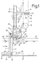
- Fig. 1 zeigt den Rechen mit Rechenreiniger in schematischer Seitenansicht, wobei in vollen Linien die Eingriffsstellung und strichpunktiert die Freigabestellung der Harke dargestellt ist.
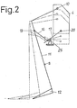
- Fig. 2 zeigt schematisch den Bewegungsablauf beim Einschwenken der Harke.
- Fig. 3 zeigt eine Überlastsicherung für den Antrieb.
- Fig. 4 zeigt einen schematischen Schnitt nach der Linie IV-IV von Fig. 1.
- Fig. 1 shows the rake with rake cleaner in a schematic side view, the full position and the dot-dash line shows the release position of the rake.
- Fig. 2 shows schematically the sequence of movements when pivoting the rake.
- Fig. 3 shows an overload protection for the drive.
- FIG. 4 shows a schematic section along the line IV-IV of FIG. 1.
Der Rechen 1 besteht aus zahlreichen parallelen lotrechten Stäben, die nur an der Sohle 2 des Strömungskanals od. dgl. verankert sind und im übrigen frei ohne gegenseitige Verbindung oder Abstützung nach oben ragen. In einer zum Rechen 1 parallelen Führung 3 ist ein Wagen 4 mit Laufrollen 5 auf- und abbewegbar geführt. Der Wagen 4 ist durch eine Lasche 6 mit einer umlaufenden Antriebskette 7 verbunden, die unten um eine Umlenkrolle 8 und oben um eine durch umkehrbaren Getriebemotor angetriebene Antriebsrolle (nicht dargestellt) umläuft. Der Antrieb ist umkehrbar, so daß die Kette sowohl bei der Aufwärtsfahrt als auch bei der Abwärtsfahrt eine positive Antriebskraft auf den Wagen 4 ausübt. Der Wagen 4 erstreckt sich über die ganze Breite des Rechens 1, und die Führung 3 kann aus zwei Führungsschienen auf beiden Seiten des Wagens 4 bestehen, oder aber, falls es sich um einen relativ schmalen Rechen 1 handelt, um eine mittig angeordnete Schiene mit vorzungsweise Doppel-T-förmigem Profil, die.vom Wagen 4 U-förmig umgriffen wird.The
An beiden Enden des Wagens 4 sind in Schwenklagern 10 gewinkelte Schwenkarme 11 gelagert, die sich im wesentlichen nach unten erstrecken und an ihrem unteren Ende die Harke 12 für die Reinigung des Rechens 1 von angeschwemmten Gut tragen. Die Harke 12 besteht aus einem die beiden Schwenkarme 11 verbindenden Balken und von diesem abstehenden Zinken 13.At both ends of the
Durch Schwenken der Schwenkarme 11 in den Schwenklagern 10 kann die Harke 12 für die Aufwärtsfahrt in eine Eingriffsstellung, in der die Zinken 13 durch die Stäbe des Rechens 1 hindurchgreifen (in Fig. 1 in vollen Linien gezeichnet) und für die Abwärtsfahrt in eine Freigabestellung, in der die Zinken 13 Abstand vom Rechen 1 haben (in Fig. 1 strichpunktiert gezeichnet) gebracht werden. Die im Ausführungsbeispiel dargestellte Vorrichtungist eine Unterstromharke, bei der die Harke auf der Abströmseite des Rechens angeordnet ist und durch den Rechen hindurch das Schwemmgut auf der Anströmseite erfaßt. Die Erfindung ist aber auch in analoger Weise bei Harken anwendbar, die auf der Anströmseite des Rechens angeordnet sind.By swiveling the
Das Ein- und Ausschwenken der Harke 12 wird gesteuert durch einen Knickhebel 15, der aus zwei Lenkern 16, 17 besteht, die in einem Gelenk 18 miteinander verbunden sind und von denen der eine bei 19 am Schwenkarm 11 und der andere bei 10 am Wagen 4 gelagert ist. Der am Wagen 4 gelagerte Lenker 17 weist ein über das Lager 20 hinausragende Verlängerung 21 und eine über das Gelenk 18 hinausragende Verlängerung 22 mit einem mit dem anderen Lenker 16 zusammenwirkenden Anschlag 23 auf.The pivoting in and out of the
Der Knickhebel 15 wirkt mit einem unteren Anschlag 25 und einem oberen Anschlag 26 zusammen. Der untere Anschlag 25 besteht aus einer Rolle, die an einer mit der Führung 3 verbundenen Konsole 27 gelagert ist. Der obere Anschlag 26 besteht ebenfalls aus einer Rolle, die an einem Hebel 28 gelagert ist, der bei 29 an einem mit der Führung 3 verbundenen Arm 30 derart schwenkbar gelagert ist, daß er aus der gezeigten Horizontalstellung nach oben in Richtung des Pfeils 31 geschwenkt werden kann, während er nach unten durch einen Anschlag 32 abgestützt wird. Der obere Anschlag 26 ist so angeordnet, daß er mit der Verlängerung 21 des Lenkers 17 zusammenwirkt, während der untere Anschlag 27 so angeordnet ist, daß ermit dem Lenker 17 und dessen anderer Verlängerung 22 zusammenwirkt.The articulated
Da der Anlenkpunkt 20 des Knickhebels 15 am Wagen 4 weiter vom Rechen 1 entfernt liegt als der Anlenkpunkt 19 am Schwenkarm 11, wird durch Strecken des Knickhebels 15 der Schwenkarm 11 und damit die Harke 12 in Richtung auf den Rechen gedrückt, während ein Einknicken des Knickhebels 15 einer Bewegung der Harke 12 vom Rechen 1 weg in die strichpunktierte Stellung entspricht. Die Schwenkungen der Schwenkarme 11 in beiden Richtungen werden durch einen doppelt wirkenden Stoßdämpfer 33, der zwischen dem Lagerpunkt 19 am Schwenkarm 11 und dem Wagen 4 angeordnet ist, gedämpft. Knickhebel 15, Anschläge 25, 26 und Stoßdämpfer 33 können entweder nur auf der einen Seite des Wagens 4 einem der Schwenkarme 11 zugeordnet oder aber, insbesondere bei breiten Rechen, auf beiden Seiten des Wagens 4 vorgesehen und beiden Schwenkarmen 11 zugeordnet sein.Since the
Die Vorrichtung funktioniert wie folgt: Bei der Abwärtsfahrt des Wagens 4 befindet sich der knickhebel 15 in der geknickten Lage, so daß die Schwenkarme 11 und die Harke 12 vom. Rechen 1 ausgeschwenkt sind. Dieses Ausschwenken kann in einfacher Weise dadurch geschehen, daß der Schwerpunkt der Schwenkarme 11 und der Harke 12 gegenüber dem Schwenklager 10 so weit nach links in Fig. 1 verlagert ist, daß bei freigegebenen Schwenkarmen 11 diese mit der Harke 12 so weit vom Rechen 1 wegpendeln, bis sich der Schwerpunkt lotrecht unter dem Lagerpunkt 10 befindet. Selbstverständlich sind auch andere, z.B. mit der Antriebskette 7 verbundene Mittel möglich, um die Harke aus dem Eingriff mit dem Rechen 1 zu bewegen. Auch kann, wenn die Lage des Schwerpunktes ein selbsttätiges Auspendeln nicht zuläßt, der Knickhebel selber zum zwangsläufigen Ausrücken herangezogen werden. In diesem Fall ist ein zusätzliches Mittel zum Arretieren notwendig.The device works as follows: When the
Am Ende der Abwärtsfahrt läuft die Verlängerung 22 des Lenkers 17 auf den Anschlag 25 auf, wodurch der Knickhebel 15 allmählich gestreckt wird, wobie sich der Anschlag 25 an der unteren Kante der Verlängerung 22 und dann des Lenkers 17 entlangbewegt. Während der Strekkung werden die Schenkarme 11 und damit die Harke 12 mit zunehmender Kraft gegen den Rechen gedrückt. Wenn der Knickhebel 15 ganz gestreckt ist und der Anschlag 23 am anderen Lenker 16 anliegt, befindet sich die Harke 12 vollständig in der Eingriffsstellung. Der Knickhebel 15 ist dabei etwas über den Totpunkt hinausgestreckt worden, so daß er während der anschließenden Aufwärtsfahrt des Wagens 4 von selbst in der gestreckten Lage verbleibt und die Harke 12 zwangsläufig in der Eingriffsstellung hält. Am Ende der Aufwärtsfahrt passiert die Verlängerung 21 des Lenkers 17 den oberen Anschlag 26, der in Richtung des Pfeils 31 ausweicht. Nach erfolgter Umschaltung des Antriebs (die durch geeignet angeordnete Endschalter bewirkt werden kann) bewegt sich der Wagen 4 wider nach unten, wobei die Verlängerung 21 des Lenkers 17 von oben her wieder auf den oberen Anschlag 26 trifft, der nun nicht ausweichen kann und den Lenker 17 entgegen dem Uhrzeigersinn verschwenkt, so daß der Knickhebel 15 eingeknickt wird und die Harke 12 in die Freigabestellung schwenken kan, die sie während der weiteren Abwärtsfahrt beibehält, bis der Lenker 17 wiederum auf den unteren Anschlag aufläuft.At the end of the downward travel, the
Man erkennt, daß das Einschwenken der Harke 12 in die Eingriffsstellung am Rechen 1 durch eine Überlagerung der Abwärtsbewegung des Wagens 4 mit der durch das Strecken des Knickhebels 15 gesteuerten Schwenkung der Schwenkarme 11 erfolgt. Durch entsprechende Bemessung des Abstandes des Lagerpunkts 10 von der Ebene des Rechens 1 und der Hebellängen der Lenker 16, 17 kann man, wie in Fig. 2 angedeutet, erreichen, daß sich durch die Überlagerung dieser Bewegungen eine Bewegungsbahn der Harke 12 ergibt, die annähernd gerade und ungefähr rechtwinklig zum Rechen verläuft. Hierdurch ist ein exaktes Einschwenken der Harke am unteren Umkehrpunkt und damit ein vollständiges Erfassen des Rechengutes ohne Rest gewährleistet.It can be seen that the pivoting of the
Die in Fig. 3 gezeigte Überlastsicherung für den Antrieb weist eine an der Führung 3 schwenkbar gelagerte Wippe 35 auf, an der das vorzugsweise angetriebene, untere Umlenkrad 8 der Antriebskette 7 gelagert ist. Stattdessen kann eine derartige Wippe auch für das obere Antriebsrad und den Antriebsmotor (nicht dargestellt) vorgesehen sein. Die Wippe 35 wird durch eine Feder 36 in einem vorgegebenen Abstand von einem mit der Führung 3 starr verbundenen Arm 37 gehalten. Die Feder 36 umgibt einen Bolzen 38, der an der Wippe 35 angelenkt ist, einen einstellbaren Anschlag 39 für die Feder 36 aufweist und an dem Arm 37 verschiebbar geführt ist. Ein Kopf 40 des Bolzens 37 kann einen Tastschalter 41 an dem Arm 37 betätigen, um den Antreibsmotor abzuschalten. Diese Betätigung erfolgt immer dann, wenn bei umlaufender Kette 7 die Harke 12 und damit der sie tragende Wagen 4 durch ein Hindernis angehalten werden und dann bei weiterdrehender Kette 7 die Umlenkrolle 8 dazu neigt, an der Kette nach der einen oder anderen Seite hochzuklettern, wobei die Wippe 35 und der Bolzen 40 gegen die Kraft der Feder 36 mitgenommen werden. Die Feder 36 dient gleichzeitig dazu, die Antriebskette 7 gespannt zu halten und auch Kettenlängung automatisch auszugleichen.The overload protection for the drive shown in FIG. 3 has a
Wie man aus Fig. 4 erkennt, sind am unteren Ende des Rechens 1 seitliche Führungen 45 vorgesehen, die mit den Enden der Harke 12 zusammenwirken und dafür sorgen, daß die Harke beim Einschwenken in eine Lage geführt wird, in der ihre Zinken 13 mit den Zwischenräumen zwischen den Stäben des Rechens 1 fluchten. Dies ist deshalb vorteilhaft, weil wegen der großen Länge und der in erwünschter Weise geringen Profilbereite der Schwenkarme 11 quer zur Abströmrichtung - die Schwenkarme stehen ja in Ruhestellung normalerweise im Durchflußquerschnitt des Gerinnes-diese seit lich wenig biegesteif sind, so daß sich die Harke bei der Abwärtsfahrt in einer gegenüber dem Rechen seitlich versetzten Stellung befinden kann, wie in Fig. 4 strichpunktiert angedeutet. Die große Länge der Schwenkarme 11 hat andererseits den Vorteil daß sich die gesamte Führungseinrichtung mit den Führungen 3 und dem Wagen 4 völlig oberhalb des Wasserspiegels 46 und sogar oberhalb der Oberkante 47 der seitlichen Begrenzungswände des Strömungskanals befinden kann. In den seitlichen Begrenzungswänden sind deshalb keine Führungsnischen od. dgl. notwendig.As can be seen from Fig. 4, 1 side guides 45 are provided at the lower end of the rake, which cooperate with the ends of the
Die aus Fig. 1 ersichtliche geknickte Form der Schwenkarme 11 hat den Vorteil, daß einerseits ihr Schwenkpunkt 10 in großem Abstand von der Ebene des Rechens 1 liegen kann, andererseits aber die Schwenkarme 11 im wesentlichen über ihre ganze Höhe parallel zum Rechen 1 verlaufen. Hierdurch besteht die Möglichkeit, an den Schwenkarmen 11 Abstüzmittel anzubringen, z.B. in Form von über die ganze Breite des Rechens 1 verlaufenden Leisten 50 mit zwischen die Stäbe des Rechens 1 greifenden Zinken od. dgl. Bei großer Höhe des Rechens 1 können auch mehrere solche Abstützleisten in verschiedener Höhe and den Schwenkarmen 11 angeordnet werden. Hierdurch wird erreicht, daß die nur an der Sohle 2 des Strömungskanals verankerten Stäbe des Rechens 1 frei und ohne gegenseitige Verbindung nach oben ragen können, was für die Bewegung der Harke 12 über das obere Ende des Rechens hinaus und für den freien Abwurf des Rechengutes vorteilhaft ist, wobei die Stäbe des Rechens 1 aber trotzdem im Normalbetrieb, wenn sich die Harke in Ruhestellung am unteren Umkehrpunkt befindet, im Bereich ihrer oberen Enden ausreichend abgestützt sind, wenn eine solche Abstützung fehlt, könnte es vorkommen, daß angeschwemmtes Rechengut die Zwischenräume zwischen den Stäben aufweitet und sich durch den Rechen hindurch zwängt.The kinked shape of the
Die geknickte Form der Schwenkarme 11 hat weiter den Vorteil, daß der Lagerpunkt 19 des Lenkers 16 gegenüber der geraden Verbindungslinie zwischen dem Schwenklager 10 und der Harke 12 in Richtung auf den Rechen 1 versetzt angeordnet sein kann, wodurch man eine größere Länge des Knickhebels 15 und damit günstigere Kraftverhältnisse erzielt.The kinked shape of the
Der umkehrbare Antrieb für den Wagen 4 kann auch in anderer Form als durch die Kette 7 realisiert werden, z.B. durch ein umlaufendes angtriebenes Seil, einen Keilriemen oder einen Zahnriemen, durch eine in der Drehrichtung umkehrbare Antriebsspindel mit entsprechender Spindelmutter am Wagen 4, oder durch einen Linearmotor.The reversible drive for the
Wie man aus Fig. 1 erkennt, haben die Zinken 13 der Harke 12 in Richtung auf die Spitzen hin abfallende Oberkanten, die mit den Stäben des Rechens 1 einen stumpfen Winkel 48 einschließen, Hierdurch wird bereits beim Einschwenken der Harke ein gewisses Anheben und Lockern des Rechengutes erreicht, Außerdem erleichtert diese abfallende Oberkante der Zinken 13 das Abstreifen oder Abwerfen des mitgenommenen Rechengutes am oberen Umkehrpunkt.As can be seen from Fig. 1, the
Bei 'der beschriebenen Ausführungsform ist der Schwerpunkt der Harke und ihrer Schwenkarme derart angeordnet, daß beim Einknicken des Knickhebels die Harke durch ihr Eigengewicht ausgeschwenkt und in der Freigabestellung gehalten wird. Zusätzlich wird das Ausschwenken auch durch den Knickhebel zwangsläufig unterstützt, solange dessen Verlängerung 21 von oben her gegen den Anschlag 26 anliegt und durch diesen geschwenkt wird. Es ist aber auch möglich, den Schwerpunkt der Harke anders anzuordnen und das Ausschwenken ausschließlich zwangsweise durch den einknickenden Knickhebel zu bewirken, wobei die Verlängerung 21 entsprechend lang zu bemessen ist. In diesem Fall, d.h. wenn sich die Harke in der Freigabestellung nicht in der Gleichgewichtslage befindet, muß eine Raste oder Verriegelung am Knickhebel oder am Harkenarm vorgesehen sein, der am Ende der Abwärtsfahrt vor dem Strecken des Knickhebels wieder zulösen wäre.In 'the described embodiment, the center of gravity of the rake and its swivel arms is arranged such that when the articulated lever bends, the rake is pivoted out by its own weight and held in the release position. In addition, the pivoting out is inevitably supported by the articulated lever, as long as its
Ein besonderer Vorteil des beschriebenen Rechenreinigers besteht darin, daß die Harke in ihrer normalen Ruhestellung zwischen den Reinigungsvorgängen sich am unteren Umkehrpunkt bereits im Eingriff am Rechenfuß befindet. Dies hat mehrere Vorteile. Die Harke beginnt nach dem Einschalten des Antriebs, welches z.B. durch ein Staumeßgerät ausgelöst werden kann, sofort mit dem Reinigen; das Problem, daß während des Stillstands am Rechenfuß angeschwemmtes Gut von den Harkenzinken erst unterfahren werden muß, tritt deshalb nicht auf. Auch kann es im Winter nicht vorkommen, daß Rechengutreste an den Zinken der Harke festfrieren und dann einen Eingriff der Harke verhindern.A particular advantage of the rake cleaner described is that the rake in its normal rest position between the cleaning processes is already in engagement with the rake foot at the lower point of reversal. This has several advantages. The rake starts after switching on the drive, which e.g. can be triggered by a congestion meter, immediately with cleaning; the problem that the rake tines have to pass underneath the material washed up on the rake foot during standstill does not arise. Nor can it occur in winter that screenings freeze on the tines of the rake and then prevent the rake from engaging.
Claims (11)
Applications Claiming Priority (2)
| Application Number | Priority Date | Filing Date | Title |
|---|---|---|---|
| DE2734119A DE2734119C3 (en) | 1977-07-28 | 1977-07-28 | Screen cleaner for bar screens in hydraulic engineering systems |
| DE2734119 | 1977-07-28 |
Publications (2)
| Publication Number | Publication Date |
|---|---|
| EP0000467A1 EP0000467A1 (en) | 1979-02-07 |
| EP0000467B1 true EP0000467B1 (en) | 1980-11-26 |
Family
ID=6015072
Family Applications (1)
| Application Number | Title | Priority Date | Filing Date |
|---|---|---|---|
| EP78100039A Expired EP0000467B1 (en) | 1977-07-28 | 1978-06-01 | Spiked rakes with cleaning device for sewage treatment plants |
Country Status (5)
| Country | Link |
|---|---|
| EP (1) | EP0000467B1 (en) |
| JP (1) | JPS5426039A (en) |
| AT (1) | AT360450B (en) |
| DE (1) | DE2734119C3 (en) |
| IT (1) | IT1103625B (en) |
Cited By (3)
| Publication number | Priority date | Publication date | Assignee | Title |
|---|---|---|---|---|
| DE3125003A1 (en) * | 1981-06-25 | 1983-01-05 | Passavant-Werke AG & Co KG, 6209 Aarbergen | Rack cleaner |
| DE3235458A1 (en) * | 1982-09-24 | 1984-03-29 | Herbert 8202 Bad Aibling Riedmayer | Cleaning device for rakes arranged on the inlet side in the brook bed or the like for small power stations |
| DE3926695A1 (en) * | 1988-09-16 | 1990-03-29 | Muhr Planung Masch Muehlenbau | Watercourse screen-cleaning mechanism - has tool drive below water level in channel |
Families Citing this family (5)
| Publication number | Priority date | Publication date | Assignee | Title |
|---|---|---|---|---|
| DE2925974C2 (en) * | 1979-06-27 | 1986-04-10 | Hugo Dipl.-Ing. 4300 Essen Kahl | Computing device for removing foreign bodies from a computing grate |
| US4392952A (en) * | 1981-04-20 | 1983-07-12 | Passavant-Werke Michelbacher Huette | Bar screen with screen cleaner for waste water treatment installations |
| FR2553803B1 (en) * | 1983-10-19 | 1986-01-17 | Barre Fernand | AUTOMATIC SCREENER |
| DE3730390A1 (en) * | 1987-09-10 | 1989-03-30 | Passavant Werke | Screen for water or sewage channels |
| CN105174323B (en) * | 2015-09-11 | 2017-10-31 | 大连诚高科技股份有限公司 | A kind of sewage treatment grille blowdown apparatus |
Family Cites Families (11)
| Publication number | Priority date | Publication date | Assignee | Title |
|---|---|---|---|---|
| DE1252150B (en) * | 1967-10-12 | |||
| DE660173C (en) * | 1934-12-21 | 1938-05-19 | Hellmut Geiger Dipl Ing | Screen cleaner for coarse screens |
| FR1007509A (en) * | 1949-12-31 | 1952-05-07 | Improvements made to installations for cleaning hydraulic system grids | |
| CH328007A (en) * | 1955-03-10 | 1958-02-28 | Faeh Vinzenz | Trash rack cleaner |
| DE1634031C3 (en) * | 1966-06-23 | 1974-07-11 | Chepos Zavody Chemickeho A Potravinarschskeho Strojirenstvi, Oborovy Podnik, Bruenn (Tschechoslowakei) | Rake with cleaning device that can be folded up to the top |
| SE309391B (en) * | 1967-03-28 | 1969-03-17 | Tolu Ab | |
| DE2137825A1 (en) * | 1971-07-28 | 1973-02-08 | Passavant Werke | Waterworks debris grating - with automatic cleaning mechanism based on double articulated dredger bucket |
| CH573519A5 (en) * | 1973-05-07 | 1976-03-15 | Schrage Friedrich | |
| JPS5344846Y2 (en) * | 1974-03-05 | 1978-10-27 | ||
| JPS5156547A (en) * | 1974-11-13 | 1976-05-18 | Hitachi Metals Ltd | JOJINKI |
| DE2517348A1 (en) * | 1975-04-19 | 1976-10-21 | Puehler Jun Karl | Bar screen cleaning rake - guided by rollers on tiltable channel frame with automatically swivelling debris scraper |
-
1977
- 1977-07-28 DE DE2734119A patent/DE2734119C3/en not_active Expired
-
1978
- 1978-06-01 EP EP78100039A patent/EP0000467B1/en not_active Expired
- 1978-06-13 AT AT429678A patent/AT360450B/en not_active IP Right Cessation
- 1978-07-25 IT IT09541/78A patent/IT1103625B/en active
- 1978-07-28 JP JP9166278A patent/JPS5426039A/en active Granted
Cited By (3)
| Publication number | Priority date | Publication date | Assignee | Title |
|---|---|---|---|---|
| DE3125003A1 (en) * | 1981-06-25 | 1983-01-05 | Passavant-Werke AG & Co KG, 6209 Aarbergen | Rack cleaner |
| DE3235458A1 (en) * | 1982-09-24 | 1984-03-29 | Herbert 8202 Bad Aibling Riedmayer | Cleaning device for rakes arranged on the inlet side in the brook bed or the like for small power stations |
| DE3926695A1 (en) * | 1988-09-16 | 1990-03-29 | Muhr Planung Masch Muehlenbau | Watercourse screen-cleaning mechanism - has tool drive below water level in channel |
Also Published As
| Publication number | Publication date |
|---|---|
| DE2734119B2 (en) | 1980-04-17 |
| AT360450B (en) | 1980-01-12 |
| DE2734119C3 (en) | 1980-12-04 |
| JPS575927B2 (en) | 1982-02-02 |
| EP0000467A1 (en) | 1979-02-07 |
| IT7809541A0 (en) | 1978-07-25 |
| ATA429678A (en) | 1980-05-15 |
| IT1103625B (en) | 1985-10-14 |
| DE2734119A1 (en) | 1979-02-08 |
| JPS5426039A (en) | 1979-02-27 |
Similar Documents
| Publication | Publication Date | Title |
|---|---|---|
| EP0443205B1 (en) | Sieve grid for the removal of solid matter from flowing fluids | |
| EP0000467B1 (en) | Spiked rakes with cleaning device for sewage treatment plants | |
| DE2020746C3 (en) | Cable guide station for rail-mounted industrial trucks | |
| DE2813593C2 (en) | Side wall for box bodies of trucks | |
| DE7630332U1 (en) | LIFT | |
| DE19505703C2 (en) | Support leg for a work device support frame | |
| DE2915341C2 (en) | Tray cleaner for stick calculators | |
| DE3101944C2 (en) | Sunroof for buildings | |
| DE3009857C2 (en) | ||
| DE10209387C1 (en) | Lifting table with two pairs of scissors type levers with spreading rollers on a horizontal guide and operated by a tape drive | |
| EP0187976B1 (en) | Locking device for telescopic elements of a lift | |
| CH648491A5 (en) | DEVICE ON A FILTER PRESS FOR SLIDING THE EACH FIRST FILTER PLATE. | |
| DE2638566C3 (en) | Outdoor conveyor with a closed track for multiple trolleys | |
| DE2925974C2 (en) | Computing device for removing foreign bodies from a computing grate | |
| EP0853172B1 (en) | Sun protecting arrangement | |
| DE2333224C2 (en) | Rake cleaning device for rakes in hydraulic engineering systems | |
| DE19827037A1 (en) | Method and device for the transport of people, preferably including bicycles and / or wheelchairs, and / or passenger and / or trucks and / or for the transport of objects and / or material | |
| DE108529C (en) | ||
| DE3121735C2 (en) | ||
| DE391166C (en) | Safety catch for bucket wagons from Schraegaufzuegen | |
| DE2419909A1 (en) | Continuous conveyor transfer frame - has telescopic beams parallel to belt for securing to adjacent frame | |
| DE873676C (en) | Link conveyor belt with two side link chains and rollers | |
| EP0650664B1 (en) | Square bale collector | |
| DE339039C (en) | Cable towing system | |
| DE3543101A1 (en) | Locking device for the telescopic sections of a lift positively guided on one another |
Legal Events
| Date | Code | Title | Description |
|---|---|---|---|
| PUAI | Public reference made under article 153(3) epc to a published international application that has entered the european phase |
Free format text: ORIGINAL CODE: 0009012 |
|
| AK | Designated contracting states |
Designated state(s): CH FR GB NL |
|
| 17P | Request for examination filed | ||
| GRAA | (expected) grant |
Free format text: ORIGINAL CODE: 0009210 |
|
| AK | Designated contracting states |
Designated state(s): CH FR GB NL |
|
| RAP2 | Party data changed (patent owner data changed or rights of a patent transferred) |
Owner name: PASSAVANT-WERKE AG & CO. KG |
|
| PGFP | Annual fee paid to national office [announced via postgrant information from national office to epo] |
Ref country code: FR Payment date: 19820429 Year of fee payment: 5 |
|
| PGFP | Annual fee paid to national office [announced via postgrant information from national office to epo] |
Ref country code: NL Payment date: 19820630 Year of fee payment: 5 |
|
| PG25 | Lapsed in a contracting state [announced via postgrant information from national office to epo] |
Ref country code: CH Effective date: 19830630 |
|
| PG25 | Lapsed in a contracting state [announced via postgrant information from national office to epo] |
Ref country code: NL Effective date: 19840101 |
|
| GBPC | Gb: european patent ceased through non-payment of renewal fee | ||
| NLV4 | Nl: lapsed or anulled due to non-payment of the annual fee | ||
| PG25 | Lapsed in a contracting state [announced via postgrant information from national office to epo] |
Ref country code: FR Free format text: LAPSE BECAUSE OF NON-PAYMENT OF DUE FEES Effective date: 19840229 |
|
| REG | Reference to a national code |
Ref country code: CH Ref legal event code: PL |
|
| REG | Reference to a national code |
Ref country code: FR Ref legal event code: ST |
|
| PG25 | Lapsed in a contracting state [announced via postgrant information from national office to epo] |
Ref country code: GB Effective date: 19881117 |
|
| PLAA | Information modified related to event that no opposition was filed |
Free format text: ORIGINAL CODE: 0009299DELT |
|
| PLBE | No opposition filed within time limit |
Free format text: ORIGINAL CODE: 0009261 |
|
| STAA | Information on the status of an ep patent application or granted ep patent |
Free format text: STATUS: NO OPPOSITION FILED WITHIN TIME LIMIT |
|
| 26N | No opposition filed |