EP0000277B1 - Hinge assembly and vehicle including same - Google Patents
Hinge assembly and vehicle including same Download PDFInfo
- Publication number
- EP0000277B1 EP0000277B1 EP78300085A EP78300085A EP0000277B1 EP 0000277 B1 EP0000277 B1 EP 0000277B1 EP 78300085 A EP78300085 A EP 78300085A EP 78300085 A EP78300085 A EP 78300085A EP 0000277 B1 EP0000277 B1 EP 0000277B1
- Authority
- EP
- European Patent Office
- Prior art keywords
- hood
- hinge assembly
- force
- cam
- hinge
- Prior art date
- Legal status (The legal status is an assumption and is not a legal conclusion. Google has not performed a legal analysis and makes no representation as to the accuracy of the status listed.)
- Expired
Links
Images

Classifications
-
- E—FIXED CONSTRUCTIONS
- E05—LOCKS; KEYS; WINDOW OR DOOR FITTINGS; SAFES
- E05F—DEVICES FOR MOVING WINGS INTO OPEN OR CLOSED POSITION; CHECKS FOR WINGS; WING FITTINGS NOT OTHERWISE PROVIDED FOR, CONCERNED WITH THE FUNCTIONING OF THE WING
- E05F1/00—Closers or openers for wings, not otherwise provided for in this subclass
- E05F1/08—Closers or openers for wings, not otherwise provided for in this subclass spring-actuated, e.g. for horizontally sliding wings
- E05F1/10—Closers or openers for wings, not otherwise provided for in this subclass spring-actuated, e.g. for horizontally sliding wings for swinging wings, e.g. counterbalance
- E05F1/12—Mechanisms in the shape of hinges or pivots, operated by springs
- E05F1/1246—Mechanisms in the shape of hinges or pivots, operated by springs with a coil spring perpendicular to the pivot axis
- E05F1/1269—Mechanisms in the shape of hinges or pivots, operated by springs with a coil spring perpendicular to the pivot axis with a traction spring
- E05F1/1276—Mechanisms in the shape of hinges or pivots, operated by springs with a coil spring perpendicular to the pivot axis with a traction spring for counterbalancing
-
- E—FIXED CONSTRUCTIONS
- E05—LOCKS; KEYS; WINDOW OR DOOR FITTINGS; SAFES
- E05Y—INDEXING SCHEME ASSOCIATED WITH SUBCLASSES E05D AND E05F, RELATING TO CONSTRUCTION ELEMENTS, ELECTRIC CONTROL, POWER SUPPLY, POWER SIGNAL OR TRANSMISSION, USER INTERFACES, MOUNTING OR COUPLING, DETAILS, ACCESSORIES, AUXILIARY OPERATIONS NOT OTHERWISE PROVIDED FOR, APPLICATION THEREOF
- E05Y2900/00—Application of doors, windows, wings or fittings thereof
- E05Y2900/50—Application of doors, windows, wings or fittings thereof for vehicles
-
- Y—GENERAL TAGGING OF NEW TECHNOLOGICAL DEVELOPMENTS; GENERAL TAGGING OF CROSS-SECTIONAL TECHNOLOGIES SPANNING OVER SEVERAL SECTIONS OF THE IPC; TECHNICAL SUBJECTS COVERED BY FORMER USPC CROSS-REFERENCE ART COLLECTIONS [XRACs] AND DIGESTS
- Y10—TECHNICAL SUBJECTS COVERED BY FORMER USPC
- Y10S—TECHNICAL SUBJECTS COVERED BY FORMER USPC CROSS-REFERENCE ART COLLECTIONS [XRACs] AND DIGESTS
- Y10S292/00—Closure fasteners
- Y10S292/14—Hood latches
Definitions
- This invention relates to hinge assemblies and more particularly to assemblies for use with the hoods of vehicle engine compartments.
- a hinge assembly for a vehicle having an engine compartment with a hood opening and a hood for closing the opening, the hinge assembly including hinge members connected to the hood and the engine compartment respectively, said members being pivotally connected to each other for swinging movement of the hood about a first horizontal axis from a closed to an open position, cam means fixed relative to the compartment hinge member and to the first axis, a force-transmitting member mounted for pivoting relative to the hood about a second axis spaced from the first axis, cam follower means for engagement with the cam means and carried by the force-transmitting member (40), and spring means arranged to apply a pivoting force to the force-transmitting member to assist opening of the hood, the hinge assembly being characterised in that the spring means is carried by the hood, in that the cam follower means is maintained in contact with the cam means during pivotting of the hood solely by the spring means, and in that the cam means has a curved surface for contact by the cam follower means
- the pivoting force of the spring means is preferably sufficient to move the hood to a partially open position without requiring any manual effort.
- the hood may swing upwardly and through a vertical position on its way to its open position, the spring means being arranged to provide assistance in the upward swinging of the hood and to oppose the movement of the hood towards this open position after it has passed through the vertical position.
- the invention also provides a vehicle with an engine compartment hood mounted on a hinge assembly of the form described above, said vehicle also including a releasable latch assembly for holding the hood in its closed position, the hood being arranged to swing to the partially open position on release of the latch assembly.
- the hinge assembly is preferably concealed within the engine compartment when the hood is in its closed position.
- the hinge assembly of the present invention is designated at 10 and is used to support a hood 12 closing the opening 14 giving access to an engine compartment 15 of a vehicle 16.
- the forward end of the opening 14 is defined by cowl 17 extending over and rearwardly from a grill 18.
- a pair of the hinge assemblies 10 are used to suuport the hood 12 for movement from the closed position relative to the opening 14 of the engine compartment 15 as seen in Figure 2 to the open position seen in full line in Figure 1 and also in Figure 5. Opening and closing movement of the hood is about a horizontal hinge axis formed by a pin indicated at 22.
- Each of the pair of hinge assemblies 10 includes a hood hinge member or subassembly 24 and an engine compartment hinge member or subassembly 26 which are connected together by pin 22.
- the hinge assemblies 10 are identical with each other and only one will be referred to hereafter.
- the hood hinge member 24 includes a pair of spaced C-shaped arm members 28 formed rigidly with a base member 30 which serves to maintain the arm members 28 in fixed, spaced-apart relationship to each other.
- the base member 30 extends generally longitudinally of the hood 12 and is adapted to be bolted to the latter.
- the forward ends of the arm members 28 pivotally receive the pin 22 which defines the horizontal hinge axis.
- the pin 22 is supported by a U-shaped bracket member 34 which is bolted or otherwise fastened to the cowl 17 of the engine compartment 10.
- the U-shaped bracket has a cam member 36 in the form of a plate extending generally longitudinally of the engine compartment at the underside of the cowl 17.
- the spaced arm members 28 support a force-transmitting member which is in the form of a pair of parallel bell cranks 40 beld in fixed, spaced-apart relationship on opposite ends of a tubular member 42.
- a pin 44 passes through the tubular member 42 and opposite ends of this pin are held in bosses 46 supported in axially aligned relationship on the inboard sides of the arm members 28.
- One arm 48 of each of the bell cranks 40 is provided with a boss 50 which supports the opposite ends of a pin 52.
- the pin 52 rotatably supports a cam follower in the form of a roller 54 which engages a cam surface 56 on the edge of the cam member 36.
- each spring 58 is connected to the free end of one of the arms 60 of each bell crank 40 and ther other end of each spring is anchored to the base member 30.
- the springs 58 tend to rotate the bell cranks 40 about the pin 44 to urge the roller 54 into engagement with the cam surface 56.
- the cam surface 56 is shaped so that as the roller 54 moves along the surface 56 the distance between the pin 44 and the surface 56 increases.
- the hood 12 to be urged upwardly under the influence of the springs 58 so that the bell cranks 40 can rotate in a clockwise sense under the action of the springs 58, this clockwise rotation of the bell cranks 40 being permitted by the increasing distance between the pin 44 and surface 50.
- the hood is maintained in its closed position by a latch assembly 64 including a latch member 66 pivoted relative to the hood 12 for movement about a latch pin 68.
- the lower end of the latch member 66 is provided with a recess 70 adapted to engage a lock pin 72 held in fixed relationship relative to the engine compartment 15.
- the latch member 66 is urged to a latched position in which the recess 70 receives the lock pin 72 by a spring 73 one end of which is anchored to the underside of hood 12 and the other end to the latch member 66 so that the latter is urged in a clockwise direction as viewed in Figure 6.
- the lower end of the latch member 66 is provided with a beveled or cam surface 74 which acts to engage the pin 72 and moves the latch member 66 in a clockwise direction during closing movement of the hood 12.
- the latch member 66 is rotated in a counterclockwise direction against the force of the spring 73 by exerting a manual force on the pad 76 located at the rearward edge of the hood 12. This moves the recess 70 of latch member 66 out of engagement with lock pin 72 to permit the springs 58 to rotate the bell cranks 40 in a clockwise direction as viewed in Figure 2 relative to the arm members 28 and cause the hood 12 to move to an ajar or slightly open position as illustrated in dash lines in Figure 1 or as shown in Figure 4.
- the hood 12 may be pivoted about its horizontal hinge axis 22 by the use of a small effort during which the hood 12 may be pivoted from its partially open position through a generally vertical position to a position at an angle where the hood rests against stops to prevent further rotation.
- the initial opening of the hood without the assistance of any physical effort is for the first twenty degrees of movement after which the hood may be rotated through an arc of approximately an additional 120 degrees to its fully open position.
- the profile of the cam surface 56 is arranged to be such that a varying force is applied to the hood 12 which is generally proportional to the effort required to move the hood through its arcuate path. It will understood, for example, that if the movement of the hood were not assisted, the effort required to open the hood would be large initially and decrease as the hood approached a generally vertical position in which its mass is in vertical balance. Movement beyond the vertically balanced position is assisted by the force of gravity until the hood reaches its fully open position seen in Figure 5.
- the springs 58 apply the roller 54 against the cam surface 56 and the profile of the cam surface 56 is such that a force is applied to the hood which is proportional to the effort that would otherwise be required to open the hood.
- the hood 12 can be moved through its remaining arcuate path by applying a relatively uniform physical effort which in actual practice is maintained at a minimum.
- the springs 58 act to resist opening movement to counteract the gravitation effect tending to open the hood.
- the roller 54 is arranged to contact the underside of the cowl 17 thus limiting further movement of the hood.
- the entire hinge assembly is concealed within the engine compartment and that the hinge or horizontal axis 22 is disposed beneath the cowl 17 and somewhat forwardly of the forward edge of the hood 12.
- the assembly 10 can be installed as a unit or the hood hinge subassembly 24 and compartment hinge subassembly 26 may be installed separately with the subsequent insertion of the hinge pin 22 since all of the components of the assembly 20 are mounted on either of the subassemblies without additional attachments for linkages or the like.
Landscapes
- Superstructure Of Vehicle (AREA)
- Closing And Opening Devices For Wings, And Checks For Wings (AREA)
Description
- This invention relates to hinge assemblies and more particularly to assemblies for use with the hoods of vehicle engine compartments.
- On some vehicles such as large tractors and off-the-road equipment hoods over the engine compartment become extremely large and heavy and difficult to open manually. Various forms of spring-assisted hinge arrangements have been employed for use on vehicles. U.S. Patent 3388417 discloses one such form of hinge. Generally such hinges have not been efficient in use since they utilize linkages which are difficult to install and maintain in operative condition and which have high frictional losses.
- It is an object of the present invention to provide an improved form of hinge assembly for mounting a vehicle engine compartment hood.
- According to the present invention there is provided a hinge assembly for a vehicle having an engine compartment with a hood opening and a hood for closing the opening, the hinge assembly including hinge members connected to the hood and the engine compartment respectively, said members being pivotally connected to each other for swinging movement of the hood about a first horizontal axis from a closed to an open position, cam means fixed relative to the compartment hinge member and to the first axis, a force-transmitting member mounted for pivoting relative to the hood about a second axis spaced from the first axis, cam follower means for engagement with the cam means and carried by the force-transmitting member (40), and spring means arranged to apply a pivoting force to the force-transmitting member to assist opening of the hood, the hinge assembly being characterised in that the spring means is carried by the hood, in that the cam follower means is maintained in contact with the cam means during pivotting of the hood solely by the spring means, and in that the cam means has a curved surface for contact by the cam follower means, the cam surface being shaped so that the distance of the point of contact of the follower means from the first axis varies as the hood swings about the first axis in such a manner that during opening of the hood the spring means applies a swinging force to the hood in opposition to the weight of the hood such that a substantially constant manual effort is required to swing the hood through a substantial part of said swing movement towards the open position.
- The pivoting force of the spring means is preferably sufficient to move the hood to a partially open position without requiring any manual effort.
- The hood may swing upwardly and through a vertical position on its way to its open position, the spring means being arranged to provide assistance in the upward swinging of the hood and to oppose the movement of the hood towards this open position after it has passed through the vertical position.
- The invention also provides a vehicle with an engine compartment hood mounted on a hinge assembly of the form described above, said vehicle also including a releasable latch assembly for holding the hood in its closed position, the hood being arranged to swing to the partially open position on release of the latch assembly.
- In order to provide a clean appearance the hinge assembly is preferably concealed within the engine compartment when the hood is in its closed position.
- One embodiment of the present invention will now be described, by way of example only, with reference to the accompanying drawings in which:
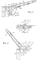
- Figure 1 is a side elevation of a vehicle with a hinged engine compartment hood;
- Figure 2 is a side elevation of a hinge assembly in accordance with the invention used to mount the hood of Figure 1 and viewed from within the engine compartment;
- Figure 3 is an end view of the hinge assembly seen in Figure 2 looking rearwardly of the vehicle;
- Figure 4 is a side elevation similar to Figure 2 but at an enlarged scale and showing the hood in a partially open position;
- Figure 5 is a view similar to Figure 4 showing the hood in a fully opened position, and
- Figure 6 is a side elevation of the hood latch assembly used to maintain the hood in a closed position.
- Referring to the drawings, the hinge assembly of the present invention is designated at 10 and is used to support a
hood 12 closing the opening 14 giving access to anengine compartment 15 of a vehicle 16. The forward end of theopening 14 is defined bycowl 17 extending over and rearwardly from agrill 18. - A pair of the
hinge assemblies 10 are used to suuport thehood 12 for movement from the closed position relative to theopening 14 of theengine compartment 15 as seen in Figure 2 to the open position seen in full line in Figure 1 and also in Figure 5. Opening and closing movement of the hood is about a horizontal hinge axis formed by a pin indicated at 22. Each of the pair ofhinge assemblies 10 includes a hood hinge member or subassembly 24 and an engine compartment hinge member orsubassembly 26 which are connected together bypin 22. Thehinge assemblies 10 are identical with each other and only one will be referred to hereafter. - The
hood hinge member 24 includes a pair of spaced C-shapedarm members 28 formed rigidly with abase member 30 which serves to maintain thearm members 28 in fixed, spaced-apart relationship to each other. Thebase member 30 extends generally longitudinally of thehood 12 and is adapted to be bolted to the latter. The forward ends of thearm members 28 pivotally receive thepin 22 which defines the horizontal hinge axis. Thepin 22 is supported by aU-shaped bracket member 34 which is bolted or otherwise fastened to thecowl 17 of theengine compartment 10. The U-shaped bracket has acam member 36 in the form of a plate extending generally longitudinally of the engine compartment at the underside of thecowl 17. - The spaced
arm members 28 support a force-transmitting member which is in the form of a pair ofparallel bell cranks 40 beld in fixed, spaced-apart relationship on opposite ends of a tubular member 42. Apin 44 passes through the tubular member 42 and opposite ends of this pin are held in bosses 46 supported in axially aligned relationship on the inboard sides of thearm members 28. One arm 48 of each of the bell cranks 40 is provided with a boss 50 which supports the opposite ends of apin 52. Thepin 52 rotatably supports a cam follower in the form of aroller 54 which engages acam surface 56 on the edge of thecam member 36. - The
roller 54 is urged into engagement with thecam surface 56 by a pair of tension springs 58. One end of eachspring 58 is connected to the free end of one of thearms 60 of each bell crank 40 and ther other end of each spring is anchored to thebase member 30. Thesprings 58 tend to rotate the bell cranks 40 about thepin 44 to urge theroller 54 into engagement with thecam surface 56. - The
cam surface 56 is shaped so that as theroller 54 moves along thesurface 56 the distance between thepin 44 and thesurface 56 increases. Thus there is a tendency for thehood 12 to be urged upwardly under the influence of thesprings 58 so that the bell cranks 40 can rotate in a clockwise sense under the action of thesprings 58, this clockwise rotation of the bell cranks 40 being permitted by the increasing distance between thepin 44 and surface 50. - The hood is maintained in its closed position by a latch assembly 64 including a
latch member 66 pivoted relative to thehood 12 for movement about a latch pin 68. The lower end of thelatch member 66 is provided with arecess 70 adapted to engage alock pin 72 held in fixed relationship relative to theengine compartment 15. Thelatch member 66 is urged to a latched position in which therecess 70 receives thelock pin 72 by a spring 73 one end of which is anchored to the underside ofhood 12 and the other end to thelatch member 66 so that the latter is urged in a clockwise direction as viewed in Figure 6. The lower end of thelatch member 66 is provided with a beveled or cam surface 74 which acts to engage thepin 72 and moves thelatch member 66 in a clockwise direction during closing movement of thehood 12. - To release the latch assembly 64 the
latch member 66 is rotated in a counterclockwise direction against the force of the spring 73 by exerting a manual force on thepad 76 located at the rearward edge of thehood 12. This moves therecess 70 oflatch member 66 out of engagement withlock pin 72 to permit thesprings 58 to rotate the bell cranks 40 in a clockwise direction as viewed in Figure 2 relative to thearm members 28 and cause thehood 12 to move to an ajar or slightly open position as illustrated in dash lines in Figure 1 or as shown in Figure 4. - Such movement is accomplished without the requirement for any additional physical effort on the part of a person opening the hood. Thereafter the
hood 12 may be pivoted about itshorizontal hinge axis 22 by the use of a small effort during which thehood 12 may be pivoted from its partially open position through a generally vertical position to a position at an angle where the hood rests against stops to prevent further rotation. - In actual practice the initial opening of the hood without the assistance of any physical effort is for the first twenty degrees of movement after which the hood may be rotated through an arc of approximately an additional 120 degrees to its fully open position.
- The profile of the
cam surface 56 is arranged to be such that a varying force is applied to thehood 12 which is generally proportional to the effort required to move the hood through its arcuate path. It will understood, for example, that if the movement of the hood were not assisted, the effort required to open the hood would be large initially and decrease as the hood approached a generally vertical position in which its mass is in vertical balance. Movement beyond the vertically balanced position is assisted by the force of gravity until the hood reaches its fully open position seen in Figure 5. Thesprings 58 apply theroller 54 against thecam surface 56 and the profile of thecam surface 56 is such that a force is applied to the hood which is proportional to the effort that would otherwise be required to open the hood. Thus after the initial opening movement of the hood to the Figure 4 position under the effort of the springs alone, thehood 12 can be moved through its remaining arcuate path by applying a relatively uniform physical effort which in actual practice is maintained at a minimum. As thehood 12 moves beyond the vertically balanced position to the position seen in Figure 5 thesprings 58 act to resist opening movement to counteract the gravitation effect tending to open the hood. As the hood approaches the fully open position shown in Figure 5 theroller 54 is arranged to contact the underside of thecowl 17 thus limiting further movement of the hood. - It will be noted that the entire hinge assembly is concealed within the engine compartment and that the hinge or
horizontal axis 22 is disposed beneath thecowl 17 and somewhat forwardly of the forward edge of thehood 12. Theassembly 10 can be installed as a unit or thehood hinge subassembly 24 andcompartment hinge subassembly 26 may be installed separately with the subsequent insertion of thehinge pin 22 since all of the components of the assembly 20 are mounted on either of the subassemblies without additional attachments for linkages or the like.
Claims (7)
Applications Claiming Priority (2)
| Application Number | Priority Date | Filing Date | Title |
|---|---|---|---|
| US05/811,408 US4134179A (en) | 1977-06-29 | 1977-06-29 | Hinge assembly |
| US811408 | 1991-12-20 |
Publications (2)
| Publication Number | Publication Date |
|---|---|
| EP0000277A1 EP0000277A1 (en) | 1979-01-10 |
| EP0000277B1 true EP0000277B1 (en) | 1981-04-29 |
Family
ID=25206468
Family Applications (1)
| Application Number | Title | Priority Date | Filing Date |
|---|---|---|---|
| EP78300085A Expired EP0000277B1 (en) | 1977-06-29 | 1978-06-27 | Hinge assembly and vehicle including same |
Country Status (7)
| Country | Link |
|---|---|
| US (1) | US4134179A (en) |
| EP (1) | EP0000277B1 (en) |
| BR (1) | BR7803961A (en) |
| CA (1) | CA1084555A (en) |
| DE (1) | DE2860641D1 (en) |
| ES (1) | ES471242A1 (en) |
| IT (1) | IT1096031B (en) |
Cited By (1)
| Publication number | Priority date | Publication date | Assignee | Title |
|---|---|---|---|---|
| USD330499S (en) | 1989-04-06 | 1992-10-27 | Holiday Rambler Corporation | Door hinge |
Families Citing this family (10)
| Publication number | Priority date | Publication date | Assignee | Title |
|---|---|---|---|---|
| US4495674A (en) * | 1982-03-05 | 1985-01-29 | Clark Equipment Company | Concealed door hinge having a double pivotal mounting |
| US5435406A (en) * | 1993-11-16 | 1995-07-25 | Chrysler Corporation | Vehicle hood mounting arrangement |
| US5611584A (en) * | 1994-06-30 | 1997-03-18 | Paccar Inc | Automatic positive hood safety lock |
| US5791428A (en) * | 1995-10-03 | 1998-08-11 | Navistar International Transportation Corp. | Locking reduced-effort hood control apparatus |
| US7909125B1 (en) * | 2001-07-13 | 2011-03-22 | Deere & Company | Dual pivoting hood support |
| US20040262828A1 (en) * | 2003-06-24 | 2004-12-30 | Bauman Walter Douglas | Device to provide initial pop-up of an automotive deck lid via a gas spring |
| US7070016B1 (en) * | 2005-03-18 | 2006-07-04 | Paccar Inc | Apparatus for vehicle hood |
| US20070158124A1 (en) * | 2006-01-11 | 2007-07-12 | Avm, Inc. | Two-way assist gas spring and retractable spring assembly |
| US7987939B2 (en) * | 2008-12-04 | 2011-08-02 | Honda Motor Co., Ltd. | Hood system with multiple open positions |
| JP7529569B2 (en) * | 2018-04-19 | 2024-08-06 | サウスコ,インコーポレイティド | Counterbalance assemblies and systems |
Family Cites Families (11)
| Publication number | Priority date | Publication date | Assignee | Title |
|---|---|---|---|---|
| US2702400A (en) * | 1951-04-06 | 1955-02-22 | Hancock Mfg Company | Hood hinge |
| DE1243561B (en) * | 1959-07-07 | 1967-06-29 | Sievers Fa Carl | Hinge with weight-compensating spring, especially for freezers |
| US3113339A (en) * | 1960-12-02 | 1963-12-10 | Chicago Forging & Mfg Co | Cammed hinge |
| GB991463A (en) * | 1961-09-15 | 1965-05-05 | Paul Matthey | Latch for hinged lids and the like |
| US3195172A (en) * | 1962-09-27 | 1965-07-20 | Gen Motors Corp | Counterbalancing hinge mechanism |
| US3388417A (en) * | 1965-06-28 | 1968-06-18 | Gen Motors Corp | Closure hinge |
| US3621509A (en) * | 1969-08-18 | 1971-11-23 | Gen Motors Corp | Vehicle body closure counterbalance |
| AT319804B (en) * | 1970-12-18 | 1975-01-10 | Blum Gmbh Julius | hinge |
| US3749437A (en) * | 1971-08-19 | 1973-07-31 | B Lynn | Beam supporting device as lifting tongs, for attachment to cables of cranes |
| US3754613A (en) * | 1971-10-28 | 1973-08-28 | Pacific Car & Foundry Co | Tilt hood assist spring |
| FR2280760A1 (en) * | 1974-07-30 | 1976-02-27 | Leurent Ghislain | Torsion bar for roof light - which opens light automatically when the ambient temp reaches a certain level |
-
1977
- 1977-06-29 US US05/811,408 patent/US4134179A/en not_active Expired - Lifetime
-
1978
- 1978-04-17 CA CA301,278A patent/CA1084555A/en not_active Expired
- 1978-06-21 BR BR787803961A patent/BR7803961A/en unknown
- 1978-06-23 IT IT7824928A patent/IT1096031B/en active
- 1978-06-27 EP EP78300085A patent/EP0000277B1/en not_active Expired
- 1978-06-27 DE DE7878300085T patent/DE2860641D1/en not_active Expired
- 1978-06-28 ES ES471242A patent/ES471242A1/en not_active Expired
Cited By (1)
| Publication number | Priority date | Publication date | Assignee | Title |
|---|---|---|---|---|
| USD330499S (en) | 1989-04-06 | 1992-10-27 | Holiday Rambler Corporation | Door hinge |
Also Published As
| Publication number | Publication date |
|---|---|
| IT7824928A0 (en) | 1978-06-23 |
| BR7803961A (en) | 1979-01-16 |
| IT1096031B (en) | 1985-08-17 |
| DE2860641D1 (en) | 1981-08-06 |
| US4134179A (en) | 1979-01-16 |
| ES471242A1 (en) | 1979-10-01 |
| CA1084555A (en) | 1980-08-26 |
| EP0000277A1 (en) | 1979-01-10 |
Similar Documents
| Publication | Publication Date | Title |
|---|---|---|
| US2984517A (en) | Torsion bar tailgate support | |
| US6618904B1 (en) | Spring loaded vehicle hinge mechanism | |
| US4125170A (en) | Forwardly pivoting bonnet or hood for a motor vehicle | |
| US4143904A (en) | Station wagon tailgate | |
| EP2044282B1 (en) | Integrated hinge assembly with spring biased prop arm | |
| US4110934A (en) | Hinge mechanism for a sliding door | |
| US5529369A (en) | Door latches for golf carts and the like | |
| US5195796A (en) | Deck lid hinge assembly | |
| US4966403A (en) | Arrangement for suspension of a door on a vehicle body | |
| EP0300669A1 (en) | Trunk lid hinge and spring assembly | |
| EP0000277A1 (en) | Hinge assembly and vehicle including same | |
| US3166783A (en) | Door hinge mechanism | |
| US20030038500A1 (en) | Vehicle deck lid power operator | |
| GB738486A (en) | Improvements in or relating to supports for closure members, such as doors for vehicles | |
| US2688764A (en) | Lid and hood hinge | |
| US6761393B2 (en) | Hinge system for motor vehicle boot lid comprising an articulated arm and a sliding arm | |
| US4068407A (en) | Sliding vehicle door | |
| JPH10175483A (en) | Wire harness arranging structure of slide door for vehicle | |
| US2620889A (en) | Combined hinge and latch mechanism for motor car hoods | |
| US2872698A (en) | Hinge construction | |
| US2343810A (en) | Combined door-hinging, door-checking, and door-holding device | |
| US2805442A (en) | Lid hinge and hold-open | |
| US3548445A (en) | Vehicle door hinge | |
| US2751625A (en) | Deck lid hinge | |
| JPH09206644A (en) | Door jig for painting |
Legal Events
| Date | Code | Title | Description |
|---|---|---|---|
| PUAI | Public reference made under article 153(3) epc to a published international application that has entered the european phase |
Free format text: ORIGINAL CODE: 0009012 |
|
| AK | Designated contracting states |
Designated state(s): DE FR GB |
|
| 17P | Request for examination filed | ||
| GRAA | (expected) grant |
Free format text: ORIGINAL CODE: 0009210 |
|
| AK | Designated contracting states |
Designated state(s): DE FR GB |
|
| REF | Corresponds to: |
Ref document number: 2860641 Country of ref document: DE Date of ref document: 19810806 |
|
| PG25 | Lapsed in a contracting state [announced via postgrant information from national office to epo] |
Ref country code: DE Effective date: 19830201 |
|
| GBPC | Gb: european patent ceased through non-payment of renewal fee | ||
| PG25 | Lapsed in a contracting state [announced via postgrant information from national office to epo] |
Ref country code: FR Free format text: LAPSE BECAUSE OF NON-PAYMENT OF DUE FEES Effective date: 19830331 |
|
| EN | Fr: translation not filed | ||
| REG | Reference to a national code |
Ref country code: FR Ref legal event code: ST |
|
| PG25 | Lapsed in a contracting state [announced via postgrant information from national office to epo] |
Ref country code: GB Effective date: 19881117 |
|
| PLBE | No opposition filed within time limit |
Free format text: ORIGINAL CODE: 0009261 |
|
| STAA | Information on the status of an ep patent application or granted ep patent |
Free format text: STATUS: NO OPPOSITION FILED WITHIN TIME LIMIT |