EP0000222B1 - Method and apparatus for continuously forming an airlaid web - Google Patents
Method and apparatus for continuously forming an airlaid web Download PDFInfo
- Publication number
- EP0000222B1 EP0000222B1 EP78200043A EP78200043A EP0000222B1 EP 0000222 B1 EP0000222 B1 EP 0000222B1 EP 78200043 A EP78200043 A EP 78200043A EP 78200043 A EP78200043 A EP 78200043A EP 0000222 B1 EP0000222 B1 EP 0000222B1
- Authority
- EP
- European Patent Office
- Prior art keywords
- ply
- moving
- reinforcing ply
- airlaid
- fiber
- Prior art date
- Legal status (The legal status is an assumption and is not a legal conclusion. Google has not performed a legal analysis and makes no representation as to the accuracy of the status listed.)
- Expired
Links
Images
Classifications
-
- D—TEXTILES; PAPER
- D04—BRAIDING; LACE-MAKING; KNITTING; TRIMMINGS; NON-WOVEN FABRICS
- D04H—MAKING TEXTILE FABRICS, e.g. FROM FIBRES OR FILAMENTARY MATERIAL; FABRICS MADE BY SUCH PROCESSES OR APPARATUS, e.g. FELTS, NON-WOVEN FABRICS; COTTON-WOOL; WADDING ; NON-WOVEN FABRICS FROM STAPLE FIBRES, FILAMENTS OR YARNS, BONDED WITH AT LEAST ONE WEB-LIKE MATERIAL DURING THEIR CONSOLIDATION
- D04H1/00—Non-woven fabrics formed wholly or mainly of staple fibres or like relatively short fibres
- D04H1/70—Non-woven fabrics formed wholly or mainly of staple fibres or like relatively short fibres characterised by the method of forming fleeces or layers, e.g. reorientation of fibres
- D04H1/72—Non-woven fabrics formed wholly or mainly of staple fibres or like relatively short fibres characterised by the method of forming fleeces or layers, e.g. reorientation of fibres the fibres being randomly arranged
-
- A—HUMAN NECESSITIES
- A61—MEDICAL OR VETERINARY SCIENCE; HYGIENE
- A61F—FILTERS IMPLANTABLE INTO BLOOD VESSELS; PROSTHESES; DEVICES PROVIDING PATENCY TO, OR PREVENTING COLLAPSING OF, TUBULAR STRUCTURES OF THE BODY, e.g. STENTS; ORTHOPAEDIC, NURSING OR CONTRACEPTIVE DEVICES; FOMENTATION; TREATMENT OR PROTECTION OF EYES OR EARS; BANDAGES, DRESSINGS OR ABSORBENT PADS; FIRST-AID KITS
- A61F13/00—Bandages or dressings; Absorbent pads
- A61F13/15—Absorbent pads, e.g. sanitary towels, swabs or tampons for external or internal application to the body; Supporting or fastening means therefor; Tampon applicators
- A61F13/15577—Apparatus or processes for manufacturing
- A61F13/15617—Making absorbent pads from fibres or pulverulent material with or without treatment of the fibres
- A61F13/1565—Making absorbent pads from fibres or pulverulent material with or without treatment of the fibres by depositing continuous layers of fibrous material between webs, e.g. wrapping layers of fibrous material
-
- A—HUMAN NECESSITIES
- A61—MEDICAL OR VETERINARY SCIENCE; HYGIENE
- A61F—FILTERS IMPLANTABLE INTO BLOOD VESSELS; PROSTHESES; DEVICES PROVIDING PATENCY TO, OR PREVENTING COLLAPSING OF, TUBULAR STRUCTURES OF THE BODY, e.g. STENTS; ORTHOPAEDIC, NURSING OR CONTRACEPTIVE DEVICES; FOMENTATION; TREATMENT OR PROTECTION OF EYES OR EARS; BANDAGES, DRESSINGS OR ABSORBENT PADS; FIRST-AID KITS
- A61F13/00—Bandages or dressings; Absorbent pads
- A61F13/15—Absorbent pads, e.g. sanitary towels, swabs or tampons for external or internal application to the body; Supporting or fastening means therefor; Tampon applicators
- A61F13/53—Absorbent pads, e.g. sanitary towels, swabs or tampons for external or internal application to the body; Supporting or fastening means therefor; Tampon applicators characterised by the absorbing medium
- A61F13/534—Absorbent pads, e.g. sanitary towels, swabs or tampons for external or internal application to the body; Supporting or fastening means therefor; Tampon applicators characterised by the absorbing medium having an inhomogeneous composition through the thickness of the pad
-
- A—HUMAN NECESSITIES
- A61—MEDICAL OR VETERINARY SCIENCE; HYGIENE
- A61F—FILTERS IMPLANTABLE INTO BLOOD VESSELS; PROSTHESES; DEVICES PROVIDING PATENCY TO, OR PREVENTING COLLAPSING OF, TUBULAR STRUCTURES OF THE BODY, e.g. STENTS; ORTHOPAEDIC, NURSING OR CONTRACEPTIVE DEVICES; FOMENTATION; TREATMENT OR PROTECTION OF EYES OR EARS; BANDAGES, DRESSINGS OR ABSORBENT PADS; FIRST-AID KITS
- A61F13/00—Bandages or dressings; Absorbent pads
- A61F13/15—Absorbent pads, e.g. sanitary towels, swabs or tampons for external or internal application to the body; Supporting or fastening means therefor; Tampon applicators
- A61F13/15577—Apparatus or processes for manufacturing
- A61F2013/15821—Apparatus or processes for manufacturing characterized by the apparatus for manufacturing
-
- A—HUMAN NECESSITIES
- A61—MEDICAL OR VETERINARY SCIENCE; HYGIENE
- A61F—FILTERS IMPLANTABLE INTO BLOOD VESSELS; PROSTHESES; DEVICES PROVIDING PATENCY TO, OR PREVENTING COLLAPSING OF, TUBULAR STRUCTURES OF THE BODY, e.g. STENTS; ORTHOPAEDIC, NURSING OR CONTRACEPTIVE DEVICES; FOMENTATION; TREATMENT OR PROTECTION OF EYES OR EARS; BANDAGES, DRESSINGS OR ABSORBENT PADS; FIRST-AID KITS
- A61F13/00—Bandages or dressings; Absorbent pads
- A61F13/15—Absorbent pads, e.g. sanitary towels, swabs or tampons for external or internal application to the body; Supporting or fastening means therefor; Tampon applicators
- A61F13/53—Absorbent pads, e.g. sanitary towels, swabs or tampons for external or internal application to the body; Supporting or fastening means therefor; Tampon applicators characterised by the absorbing medium
- A61F13/534—Absorbent pads, e.g. sanitary towels, swabs or tampons for external or internal application to the body; Supporting or fastening means therefor; Tampon applicators characterised by the absorbing medium having an inhomogeneous composition through the thickness of the pad
- A61F2013/53445—Absorbent pads, e.g. sanitary towels, swabs or tampons for external or internal application to the body; Supporting or fastening means therefor; Tampon applicators characterised by the absorbing medium having an inhomogeneous composition through the thickness of the pad from several sheets
-
- Y—GENERAL TAGGING OF NEW TECHNOLOGICAL DEVELOPMENTS; GENERAL TAGGING OF CROSS-SECTIONAL TECHNOLOGIES SPANNING OVER SEVERAL SECTIONS OF THE IPC; TECHNICAL SUBJECTS COVERED BY FORMER USPC CROSS-REFERENCE ART COLLECTIONS [XRACs] AND DIGESTS
- Y10—TECHNICAL SUBJECTS COVERED BY FORMER USPC
- Y10T—TECHNICAL SUBJECTS COVERED BY FORMER US CLASSIFICATION
- Y10T156/00—Adhesive bonding and miscellaneous chemical manufacture
- Y10T156/10—Methods of surface bonding and/or assembly therefor
- Y10T156/1002—Methods of surface bonding and/or assembly therefor with permanent bending or reshaping or surface deformation of self sustaining lamina
- Y10T156/1051—Methods of surface bonding and/or assembly therefor with permanent bending or reshaping or surface deformation of self sustaining lamina by folding
Definitions
- This invention relates to fibrous absorbent structures and in particular to reinforced airlaid fibrous bodies.
- Absorbent fibrous structures comprised of low strength absorbent materials such as airlaid wood pulp fibers are well known in the disposable absorbent bandage art.
- tissue paper or other web materials which are substantially impervious to the passage of fibers to act, for example, as a reinforcing agent, as a fluid baffle to distribute absorbed fluids within the absorbent fluff structure, as a partitioning agent or the like.
- Addition of such internal plies which have a width substantially equal to that of the absorbent fibrous webs located on the uppermost and lowermost surfaces thereof has typically been provided by utilizing a multiplicity of discrete forming zones with a separate fiber supply source for each zone.
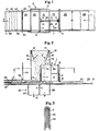
- FIG 1 is a plan view of a preferred embodiment of the present invention wherein a wet strength tissue ply 20 is incorporated intermediate the uppermost and lowermost surfaces of an absorbent pad for a disposable absorbent article to improve its in use integrity.
- the wet stength tissue ply 20 is directed about a folding board mechanism 1 prior to entry of the tissue ply into a fiber deposition chute 12 fed by a source of discrete fibrous material from e.g. a fiber disintegration apparatus (not shown).
- the lower region of the chute 12 defines a chamber wherein a lowermost layer of absorbent airfelt 21 is formed beneath the surface of the tissue ply 20 and an uppermost layer of airfelt 22 is formed adjacent its uppermost surface.
- a layer of wet strength tissue paper 23 is employed adjacent the lowermost surface of the layer of airfelt 21, and an uppermost layer of tissue paper 24 is employed adjacent the uppermost surface of the layer of airfelt 22.
- the folding board 1 comprises a pair of identical planar isosceles triangles 2, 4 having an included angle of approximately 90° at their respective apexes, connected to one another at their altitudes by means of a vertical planar member 3.
- a layer of reinforcing wet strength tissue paper 20 having a width W substantially equal to that of the airfelt layers 21, 22 is preferably fed in the same direction and at the same velocity V as the foraminous supporting surface 11.
- the tissue ply 20 is caused to alter its path of travel from a horizontal direction to a vertical direction by virtue of being wrapped about direction changing roller 5 located near the base of the isosceles right triangle 2 forming a portion of the folding board 1.
- the lateral edge portions of the ply are caused to remain in contact with both the leading and trailing surfaces of the triangle by virtue of angular guides 7, 8 located adjacent the interior corners formed between vertical planar member 3 and the planar triangle 2.
- the angular guide members 7, 8 force the tissue ply 20 to assume an inverted U-shape as illustrated in the cross-section of Figure 3.
- the vertical planar member 3 does conveniently serve to maintain planar isosceles triangles 2, 4 in longitudinal alignment with one another, its presence is not essential to guide the inverted U-shaped tissue ply 20 intermediate the triangles 2, 4.
- the inverted U-shaped shroud 28 which connects angles 9, 10 to one another serves to prevent fibers within the deposition chute 12 from collecting on the inverted U-shaped tissue ply 20 prior to passage of the ply through the limited clearance corners formed between angles 9, 10, triangle 4 and vertical planar member 3. Collection of fibers on the inverted U-shaped tissue ply 20 could cause jamming or tearing at these points.
- the tissue ply 20 is introduced into the fiber deposition chute 12 while in the inverted U-shape in order to permit formation of a substantially planar lowermost layer of airfelt 21 which lies adjacent the lowermost surface of the tissue ply 20 in the finished absorbent pad embodiment.
- Internal airflow baffling techniques well known in the art may be employed within the vacuum chamber 26 to minimize any discontinuities in the cross-machine direction uniformity of the airfelt layer 21 which might otherwise occur due to the minor obstruction presented by the thin U-shaped shroud 28.
- the lowermost layer of airfelt 21 is formed directly over a layer of envelope tissue 23 similar to that utilized as the reinforcing ply 20 in the forwardmost portion 13 of the fiber deposition chute 12.
- the vacuum chamber 25 located adjacent the lowermost surface of the moving foraminous support member 11 is preferably divided into two distinct segments 26, 27 by means of an adjustable dividing wall 19 which may be advanced or retarded in the machine direction.
- the vacuum chamber 25 is preferably segmented as outlined above in order to permit the application of differing vacuum levels between the leading portion 13 of the fiber deposition chute 12 and the trailing portion 14, since the trailing portion encounters more resistance to air flow than the leading portion due to the presence of the fibrous layer 21 and the reinforcing tissue ply 20 during formation of the uppermost layer of airfelt 22.
- the tissue ply 20 is maintained in an inverted U-configuration until the desired thickness of airfelt layer 21 has been obtained.
- the relative and total thickness of the respective airfelt layers 21 and 22 is controllable not only by the rate of fiber deposition within the chute 12, but also by the level of vacuum applied beneath the moving formaminous support member 11 in vacuum chamber segments 26 and 27, the machine direction positioning of the segmenting wall 19 within the vacuum chamber 25, and the machine direction positioning of the planar isosceles right triangle 4 connected to vertical planar member 3.
- baffle plates 15 and 16 which extend across the entire width of the fiber deposition chute 12, and which may be adjusted about pivot points 17 and 18, may also be employed to direct the flow of fibers toward either the leading portion 13 or the trailing portion 14 of the deposition chute 12, depending upon the desired split between uppermost layer 22 and lowermost layer 21.
- Angular guides 9 and 10 force the tissue ply 20 to remain in contact with the leading surface of isosceles right triangle 4 which is identical in size and shape to the isosceles right triangle 2 as the centerline of a tissue ply 20 is directed about the apex of triangle 4. This in turn forces the tissue ply 20 to resume a planar configuration as it passes the base portion of the trailing surface of the triangle 4.
- Direction changing roll 6 restores the tissue ply 20 to its original direction of travel and exposes the uppermost surface of the ply to the deposition of fibers in the downstream portion 14 of the fiber deposition chute 12.
- a fibrous airlaid web 22 is thus formed adjacent the uppermost surface of the tissue ply 20 prior to passage of the assemblage from the fiber deposition chute 12.
- a wet strength tissue ply 24 is preferably thereafter brought into contact with the uppermost surface of the absorbent airfelt layer 22 about direction changing roller 30 as shown in Figure 2 to form a reinforced fibrous structure encapsulated on both sides by wet strength tissue piies 23, 24.
- the relative position of the internally located tissue ply 20 may be adjusted intermediate the uppermost and lowermost surfaces of the resultant absorbent pad structure by advancing or retarding the position of the folding board 1 and the direction changing rollers 5, 6 which are preferably mounted thereto within the fiber deposition chute 12. This of course necessitates a corresponding adjustment of angular guides 7, 8, 9 and 10 and shroud 28 in order to maintain the tissue ply 20 in contact with the surfaces of triangles 2, 4.
- the U-shaped shroud 28 illustrated in cross-section in Figure 3 is preferably employed in the practice of the present invention to avoid the collection of fibers on the uppermost surfaces of the wet strength tissue ply 20 prior to direction of the ply intermediate angular guides 9 and 10 located at the interior corners formed between isosceles triangle 4 and vertical planar member 3. This is necessary to avoid hangup or jamming of the ply within the relatively tight clearances provided intermediate the guides 9 and 10 and the interior corners formed by triangle 4 and vertical planar member 3.
- the shroud 28 must also be adjustable such that adjustment of the triangle 4 in the machine direction will not result in exposure of the inverted U-shaped tissue ply 20 to the stream of fibers present in the leading portion 13 of fiber deposition chute 12.
- separating wall 19 in vacuum chamber 25 is adjustable so as to vertically coincide with the position ultimately assumed by isosceles triangle 4 within the deposition chute 12.
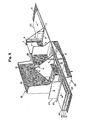
- Figure 4 is a simplified perspective illustration of the embodiment of the present invention illustrated in Figures 1-3. Selected portions of the fiber deposition chute 12 have been broken away to illustrate with maximum clarity the present pad forming operation.
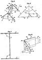
- the folding board 1 illustrated in Figures 1-4 is more clearly set forth in Figures 5-7. While it is not essential that the folding board 1 be comprised of solid sheet stock as illustrated in Figure 5, the folding board preferably comprises a pair of planar isosceles right triangles 2, 4 connected to one another by means of a vertical planar member 3 corresponding in height to the altitude of each isosceles triangle. In order to minimize the vertical height requirement for a folding board of the present invention, it is preferable that the centerline of the tissue ply 20 be made to coincide with the altitude of both triangles during its passage over the folding board.
- the included right angle a of triangle 2 is surrounded by equal length legs 42, 43 while the included right angle a of identical triangle 4 is surrounded by equal length legs 45, 46.
- the base 44 of isosceles triangle 2 and the base 47 of isosceles triangle 4 connect the respective equal length leg segments of the triangles.
- Lines 40 and 41 illustrated in Figure 5 represent the altitudes of right triangles 2 and 4, respectively.
- the angle ⁇ in each case amounts to 90 degrees
- the included right angle a of each triangle is bisected by its respective altitude.
- the angle y between the altitude 40 of right triangle 2 and the base of vertical planar member 3 and the angle 8 between the altitude 41 of triangle 4 and the base of vertical planar member 3 in the illustrated embodiment are also equal to 90 degrees.
- each point on the incoming ply 20 must travel the same linear distance in traversing the surface of the forming board from entry thereon near the base 44 of isosceles right triangle 2 until its exit therefrom near the base 47 of isosceles right triangle 4.
- the paths followed by a pair of corresponding points located on opposite sides of the ply centerline is represented by lines 48 and 49 in Figure 5.
- Figure 6 is a discharge end view of the folding board 1 illustrated in Figure 5.
- the sum of any given pair of lines A" + B " must be constant, where An is any line parallel to the altitude 41 of the triangle and B " is the corresponding horizontal distance of the line An from the altitude 41.
- FIG 7 is a plan view of the folding board 1 illustrated in Figure 5, the lowermost layer of absorbent fibers 21 is formed while the ply 20 is in the inverted U-configuration intermediate triangles 2, 4.
- angle 0 formed between triangle 2 and vertical planar member 3 and the angle 0 formed between triangle 4 and vertical planar member 3 amounts to 90 degrees in the embodiment illustrated in Figures 1-7, it should be noted that the angles 0 and 0 need not equal one another, nor is it required that either angle be a right angle.
- the angle of infeed and outfeed of the tissue ply 20 may be varied as desired, provided only that the angles employed permit the tissue ply to be maintained in substantial surface contact with the triangles at the inside corners formed between triangles 2, 4 and vertical planar member 3.
- vertical planar member 3 is not an essential portion of the present folding board 1, but rather is employed in a preferred embodiment of the present invention as a means of securing the triangles in longitudinal alignment with one another, a feature which is critical to the practice of the present invention.
- a slight relief is preferably provided at the leading and trailing surfaces of the triangle 2, 4 at their respective apexes. While this causes a very slight deviation in the theoretical constant length criteria described above, the practical and beneficial effect is to minimize the tendency of the ply 20 to rip or tear at points of stress concentration.
- Figure 8 represents yet another particularly preferred embodiment of a folding board 50 which may be employed in the practice of the present invention in a system similar to that illustrated in Figures 1 and 2.
- a vertical support member 57 is joined to one of the equal length leg segments 58 of an isosceles right triangle 52 having its included right angle 1/1 located intermediate equal length legs 58, 56.
- the triangle 52 preferably forms an angle ⁇ of 90 degrees with vertical planar member 57.
- a ply of reinforcing tissue 20' having a width W' is fed in a vertical plane in a direction parallel to the direction of travel of the foraminous support member 11 illustrated in Figures 1 and 2.
- the incoming ply 20' is wrapped about leg 58 of the isosceles right triangle 52 such that it contacts the trailing surface of the triangle and its borders parallel the equal length leg 56.
- the ply 20' is thereafter directed about the hypotenuse 54 of the planar triangle 52 and downwardly in a direction parallel to leg 58 while in contact with the leading surface of the triangle.
- the ply 20' is finally directed about equal length leg 56 of the triangle and thereafter continues in a manner similar to that illustrated in Figures 1 and 2.
- the particular embodiment illustrated in Figure 8 offers the advantage that the tissue ply 20' does not require the use of any external guides to hold it in intimate contact with the surfaces of the isoceles right triangle 52, but rather is wrapped tightly thereabout by means of the tension employed to draw the ply through the folding board 50. Furthermore, there is no interruption of the fiber forming zone in the leading portion 13 of the fiber deposition chute 12, since the vertical support member 57 may be located adjacent the edge of the fibrous web 21. Accordingly, it is feasible to obtain a uniform cross-machine direction basis weight and profile in the fibrous airfelt web 21 formed adjacent the lowermost surface of the ply 20'.
- the embodiment illustrated in Figure 8 does, however, require greater overhead clearance at the fiber deposition chute 12 due to the fact that the ply 20' is not folded upon itself, as in the case of the embodiment illustrated in Figures 1-3.
- the outermost tissue plies 23 and 24 illustrated in Figures 1 and 2 may be somewhat wider than the tissue ply 20 and the airfelt web portions 21 and 22.
- the lateral edge portions of plies 23 and 24 may be secured to one another by folding, by adhesives, or by other means well known in the art to form a continuous encapsulating envelope.
- a continuous layer of moisture-pervious topsheet material may be secured in superposed relation to the continuous envelope. Absrobent pad segments of predetermined length are thereafter cut from the continuous envelope.
- the absorbent pad segments are preferably rotated 90° prior to securement to a continuous web of moisture-impervious backsheet material about their periphery to form a continuous web of disposable absorbent bandages, such as diapers. Individual diapers are thereafter cut from the continuous web intermediate the absorbent pad segments.
- U.S. Patent 3,952,745 issued to Duncan on April 27, 1976 and incorporated herein by reference is generally representative of such a construction. Aligning the machine direction of the tissue plies 20, 23 and 24 parallel to the waistband portions of the diaper in this manner is generally desirable since it aligns the tissue's direction of maximum strength with the direction in which the greatest tensile loads are typically applied in use.
- the invention disclosed herein may be utilized to provide plies which are perforate or imperforate and which are either continuous or discontinuous in the cross machine direction intermediate a pair of fibrous webs in a single fiber deposition zone.
- multiple plies may be simultaneously fed utilizing an embodiment of the present invention, or multiple stages of the present invention may be employed to provide multiple reinforcing plies within a single structure, each ply being separated from the next by a fibrous layer.
Landscapes
- Health & Medical Sciences (AREA)
- Engineering & Computer Science (AREA)
- Animal Behavior & Ethology (AREA)
- General Health & Medical Sciences (AREA)
- Biomedical Technology (AREA)
- Heart & Thoracic Surgery (AREA)
- Vascular Medicine (AREA)
- Life Sciences & Earth Sciences (AREA)
- Manufacturing & Machinery (AREA)
- Epidemiology (AREA)
- Public Health (AREA)
- Veterinary Medicine (AREA)
- Textile Engineering (AREA)
- Absorbent Articles And Supports Therefor (AREA)
- Folding Of Thin Sheet-Like Materials, Special Discharging Devices, And Others (AREA)
- Orthopedics, Nursing, And Contraception (AREA)
- Nonwoven Fabrics (AREA)
- Preliminary Treatment Of Fibers (AREA)
Description
- This invention relates to fibrous absorbent structures and in particular to reinforced airlaid fibrous bodies.
- Absorbent fibrous structures comprised of low strength absorbent materials such as airlaid wood pulp fibers are well known in the disposable absorbent bandage art. In certain of these prior art fibrous pad structures it has been found desirable to employ one or more internally located plies of tissue paper or other web materials which are substantially impervious to the passage of fibers to act, for example, as a reinforcing agent, as a fluid baffle to distribute absorbed fluids within the absorbent fluff structure, as a partitioning agent or the like. Addition of such internal plies which have a width substantially equal to that of the absorbent fibrous webs located on the uppermost and lowermost surfaces thereof has typically been provided by utilizing a multiplicity of discrete forming zones with a separate fiber supply source for each zone. However, the multiple forming zone approach typically employed by such prior art systems requires considerable converting line space and involves a duplication of disintegrating and air layering equipment for each absorbent fibrous layer employed in the resultant structure. Furthermore, altering the position of the internal ply relative to the uppermost and lowermost surfaces of the finished absorbent pad typically requires a complex adjustment procedure for each fiber deposition zone in the system.
- Accordingly, it is an object of the present invention to provide method and apparatus for forming an airlaid fiber impervious fibrous fluff web provided with a substantially planar fiber impervious internal reinforcing ply whose width is substantially coextensive with that of the web.
- It is a preferred object of the present invention to provide method and apparatus for easily altering the position of the internal ply relative to the uppermost and lowermost surfaces of the absorbent pad in question.
- It is yet another object of the present invention to provide method and apparatus for the continuous formation of an internally reinforced airlaid fibrous fluff web in a single fibre deposition zone, the reinforcement comprising a substantially planar fiber-impervious internal reinforcing ply having substantially the same width as said fibrous web, and the deposition zone having an overall length no greater than that required to form an identical absorbent pad of the comparable basis weight without said center ply.
- In one method aspect of the present invention the aforementioned objectives are accomplished by carrying out the steps of:
- (a) continuously feeding said substantially planar reinforcing ply (2) in a first direction in a first plane;
- (b) introducing said moving reinforcing ply into a single fiber deposition zone in which is disposed a foraminous support surface (11) moving in said first direction while the ply is oriented so that the direction of fiber flow is substantially parallel to the width of said ply, to vacuum form on said support surface, a first portion (21) of said airlaid fibrous fluff web;
- (c) guiding said moving reinforcing ply into contact with a first equal length leg portion (58) of the trailing surface of a planar isosceles right angled triangle, (52) said first equal length leg portion being oriented perpendicular to said first direction of travel of said ply (20);
- (d) wrapping said moving reinforcing ply about opposite surfaces of said planer right triangle (52) by passing said ply about the hypotenuse thereof;
- (e) restoring said moving ply to said first direction of travel by passing said moving ply about the second equal length leg portion (56) of said triangle (52), thereby causing said ply to assume a planar condition in a second plane perpendicular to said first plane, said ply being positioned with its lowermost surface immediately adjacent said first airlaid fibrous fluff web portion (21);
- (f) exposing the uppermost surface of said moving reinforing ply to said fiber deposition zone while in a planar condition to vacuum form a second portion (22) of said airlaid fibrous fluff web adjacent the uppermost surface of said reinforcing ply (20); and
- (g) removing said ply and said airlaid web portions from said fiber deposition zone.
- In a second method aspect of the present invention the objectives are accomplished by carrying out the steps of:
- (a) continuously feeding said substantially planar reinforcing ply (20) in a first direction in a first plane;
- (b) guiding said moving reinforcing ply about a first direction changing means (5) and into contact with the leading surface of a first planar isosceles right angled triangle (2) said triangle having its altitude oriented perpendicular to said first direction of travel of said ply;
- (c) wrapping said moving reinforcing ply about opposite surfaces of said first planar triangle;
- (d) restoring said moving ply to its first direction of travel by directing said ply about the apex of said first triangle while maintaining the lateral edge portions of said moving ply in contact with the leading and trailing surfaces of said first triangle, thereby causing said ply to fold about itself in a second plane perpendicular to said first plane;
- (e) introducing said moving reinforcing ply to a single fiber deposition zone in which is disposed a foraminous support surface (11) moving in said first direction while the ply is in a folded configuration, to vacuum form on said support surface, a first portion (21) of said airlaid fibrous fluff web;
- (f) wrapping said moving reinforcing ply about opposite surfaces of a second isosceles triangle (4) identical to and longitudinally aligned with said first triangle (2) and having its altitude oriented perpendicular to said first direction of travel such that the lateral edges of said moving ply are guided on opposite sides of the apex of said second triangle as said moving ply is directed about the apex thereof, the lateral edges of said moving ply being maintained in contact with the leading and trailing surfaces of said second triangle, thereby restoring said ply to a planar condition;
- (g) directing said moving reinforcing ply about a second direction changing means (6) to restore it to said first direction of travel and to bring the lowermost surface thereof into contact with the first airlaid fibrous fluid portion (21)
- (h) exposing the uppermost surface of said moving reinforcing ply to said fiber deposition zone while in a planar condition to vacuum form a second portion (22) of said airlaid fibrous fluff web adjacent the uppermost surface of said reinforcing ply; and
- (i) removing said ply and said airlaid web portions from said fiber deposition zone.
- While the specification concludes with claims particularly pointing out and distinctly claiming the subject matter which is regarded as forming the present invention, it is believed that the invention will be better understood from the following description taken in connection with the accompanying drawings in which:
- Figure 1 is a simplified cross-sectional illustration of a pad forming mechanism employing a preferred embodiment of the present invention taken along Section Line 1-1 in Figure 2;
- Figure 2 is a complete side elevation view of the pad forming mechanism illustrated in cross-section Figure 1.
- Figure 3 is an enlarged cross-sectional illustration taken along Section line 3-3 in Figure 2;
- Figure 4 is a simplified perspective view of the pad forming mechanism illustrated in Figures 1-3;
- Figure 5 is a simplified schematic illustration of the folding board portion of the mechanism utilized in a preferred embodiment of the present invention;
- Figure 6 is a discharge end view of the folding board illustrated in Figure 5;
- Figure 7 is a plan view of the folding board illustrated in Figure 5; and
- Figure 8 is a simplified perspective view of yet another folding board suitable for use in the present invention.
- Figure 1 is a plan view of a preferred embodiment of the present invention wherein a wet
strength tissue ply 20 is incorporated intermediate the uppermost and lowermost surfaces of an absorbent pad for a disposable absorbent article to improve its in use integrity. As can be seen more clearly from Figure 2, the wetstength tissue ply 20 is directed about a folding board mechanism 1 prior to entry of the tissue ply into afiber deposition chute 12 fed by a source of discrete fibrous material from e.g. a fiber disintegration apparatus (not shown). The lower region of thechute 12 defines a chamber wherein a lowermost layer ofabsorbent airfelt 21 is formed beneath the surface of thetissue ply 20 and an uppermost layer ofairfelt 22 is formed adjacent its uppermost surface. In a particularly preferred embodiment of the present invention, a layer of wetstrength tissue paper 23 is employed adjacent the lowermost surface of the layer ofairfelt 21, and an uppermost layer oftissue paper 24 is employed adjacent the uppermost surface of the layer ofairfelt 22. - In the embodiment illustrated in Figures 1 and 2 the folding board 1 comprises a pair of identical
planar isosceles triangles planar member 3. A layer of reinforcing wetstrength tissue paper 20 having a width W substantially equal to that of theairfelt layers surface 11. Thetissue ply 20 is caused to alter its path of travel from a horizontal direction to a vertical direction by virtue of being wrapped aboutdirection changing roller 5 located near the base of the isoscelesright triangle 2 forming a portion of the folding board 1. While the centerline of the movingtissue ply 20 is caused to coincide with the altitude of the isoscelesright triangle 2 in the illustrated embodiment, the lateral edge portions of the ply are caused to remain in contact with both the leading and trailing surfaces of the triangle by virtue ofangular guides 7, 8 located adjacent the interior corners formed between verticalplanar member 3 and theplanar triangle 2. When thetissue ply 20 is forced to resume its original direction of travel about the apex of the isoscelesright triangle 2, theangular guide members 7, 8 force thetissue ply 20 to assume an inverted U-shape as illustrated in the cross-section of Figure 3. While the verticalplanar member 3 does conveniently serve to maintain planarisosceles triangles U-shaped tissue ply 20 intermediate thetriangles shroud 28 which connectsangles deposition chute 12 from collecting on the invertedU-shaped tissue ply 20 prior to passage of the ply through the limited clearance corners formed betweenangles triangle 4 and verticalplanar member 3. Collection of fibers on the invertedU-shaped tissue ply 20 could cause jamming or tearing at these points. - The
tissue ply 20 is introduced into thefiber deposition chute 12 while in the inverted U-shape in order to permit formation of a substantially planar lowermost layer ofairfelt 21 which lies adjacent the lowermost surface of thetissue ply 20 in the finished absorbent pad embodiment. Internal airflow baffling techniques well known in the art may be employed within thevacuum chamber 26 to minimize any discontinuities in the cross-machine direction uniformity of theairfelt layer 21 which might otherwise occur due to the minor obstruction presented by thethin U-shaped shroud 28. In a particularly preferred embodiment, the lowermost layer ofairfelt 21 is formed directly over a layer ofenvelope tissue 23 similar to that utilized as thereinforcing ply 20 in theforwardmost portion 13 of thefiber deposition chute 12. As can be seen in Figure 2, thevacuum chamber 25 located adjacent the lowermost surface of the movingforaminous support member 11 is preferably divided into twodistinct segments wall 19 which may be advanced or retarded in the machine direction. Thevacuum chamber 25 is preferably segmented as outlined above in order to permit the application of differing vacuum levels between the leadingportion 13 of thefiber deposition chute 12 and thetrailing portion 14, since the trailing portion encounters more resistance to air flow than the leading portion due to the presence of thefibrous layer 21 and thereinforcing tissue ply 20 during formation of the uppermost layer ofairfelt 22. - As is apparent from Figures 1 and 2, the
tissue ply 20 is maintained in an inverted U-configuration until the desired thickness ofairfelt layer 21 has been obtained. The relative and total thickness of therespective airfelt layers chute 12, but also by the level of vacuum applied beneath the movingformaminous support member 11 invacuum chamber segments segmenting wall 19 within thevacuum chamber 25, and the machine direction positioning of the planar isoscelesright triangle 4 connected to verticalplanar member 3. Furthermore,baffle plates fiber deposition chute 12, and which may be adjusted aboutpivot points portion 13 or thetrailing portion 14 of thedeposition chute 12, depending upon the desired split betweenuppermost layer 22 andlowermost layer 21. -
Angular guides tissue ply 20 to remain in contact with the leading surface of isoscelesright triangle 4 which is identical in size and shape to the isoscelesright triangle 2 as the centerline of atissue ply 20 is directed about the apex oftriangle 4. This in turn forces thetissue ply 20 to resume a planar configuration as it passes the base portion of the trailing surface of thetriangle 4. Direction changing roll 6 restores thetissue ply 20 to its original direction of travel and exposes the uppermost surface of the ply to the deposition of fibers in thedownstream portion 14 of thefiber deposition chute 12. Afibrous airlaid web 22 is thus formed adjacent the uppermost surface of thetissue ply 20 prior to passage of the assemblage from thefiber deposition chute 12. A wet strength tissue ply 24 is preferably thereafter brought into contact with the uppermost surface of theabsorbent airfelt layer 22 aboutdirection changing roller 30 as shown in Figure 2 to form a reinforced fibrous structure encapsulated on both sides by wetstrength tissue piies - As has been pointed out earlier herein, the relative position of the internally located tissue ply 20 may be adjusted intermediate the uppermost and lowermost surfaces of the resultant absorbent pad structure by advancing or retarding the position of the folding board 1 and the
direction changing rollers 5, 6 which are preferably mounted thereto within thefiber deposition chute 12. This of course necessitates a corresponding adjustment ofangular guides shroud 28 in order to maintain the tissue ply 20 in contact with the surfaces oftriangles U-shaped shroud 28 illustrated in cross-section in Figure 3 is preferably employed in the practice of the present invention to avoid the collection of fibers on the uppermost surfaces of the wet strength tissue ply 20 prior to direction of the ply intermediateangular guides isosceles triangle 4 and verticalplanar member 3. This is necessary to avoid hangup or jamming of the ply within the relatively tight clearances provided intermediate theguides triangle 4 and verticalplanar member 3. As will thus be apparent to those skilled in the art, theshroud 28 must also be adjustable such that adjustment of thetriangle 4 in the machine direction will not result in exposure of the inverted U-shaped tissue ply 20 to the stream of fibers present in the leadingportion 13 offiber deposition chute 12. In a most preferred embodiment of the present invention, separatingwall 19 invacuum chamber 25 is adjustable so as to vertically coincide with the position ultimately assumed byisosceles triangle 4 within thedeposition chute 12. - Figure 4 is a simplified perspective illustration of the embodiment of the present invention illustrated in Figures 1-3. Selected portions of the
fiber deposition chute 12 have been broken away to illustrate with maximum clarity the present pad forming operation. - The geometry of the folding board 1 illustrated in Figures 1-4 is more clearly set forth in Figures 5-7. While it is not essential that the folding board 1 be comprised of solid sheet stock as illustrated in Figure 5, the folding board preferably comprises a pair of planar isosceles
right triangles planar member 3 corresponding in height to the altitude of each isosceles triangle. In order to minimize the vertical height requirement for a folding board of the present invention, it is preferable that the centerline of the tissue ply 20 be made to coincide with the altitude of both triangles during its passage over the folding board. Thus, in the simple embodiment illustrated in Figure 4 the included right angle a oftriangle 2 is surrounded byequal length legs identical triangle 4 is surrounded byequal length legs base 44 ofisosceles triangle 2 and thebase 47 ofisosceles triangle 4 connect the respective equal length leg segments of the triangles.Lines right triangles altitude 40 ofright triangle 2 and the base of verticalplanar member 3 and theangle 8 between thealtitude 41 oftriangle 4 and the base of verticalplanar member 3 in the illustrated embodiment are also equal to 90 degrees. - The principle upon which the folding board 1 illustrated in Figures 1-7 operates is that each point on the
incoming ply 20 must travel the same linear distance in traversing the surface of the forming board from entry thereon near thebase 44 of isoscelesright triangle 2 until its exit therefrom near thebase 47 of isoscelesright triangle 4. The paths followed by a pair of corresponding points located on opposite sides of the ply centerline is represented bylines altitude 41 of the triangle and B" is the corresponding horizontal distance of the line An from thealtitude 41. - As should be clear from Figure 7 which is a plan view of the folding board 1 illustrated in Figure 5, the lowermost layer of
absorbent fibers 21 is formed while theply 20 is in the inverted U-configurationintermediate triangles ply 20 as it passes through thefiber deposition chute 12 in the inverted U-configuration in order to minimize any cross-machine direction non-uniformity in thelowermost airlaid web 21 formed adjacent its lowermost surface. - While it should be observed that the angle 0 formed between
triangle 2 and verticalplanar member 3 and the angle 0 formed betweentriangle 4 and verticalplanar member 3 amounts to 90 degrees in the embodiment illustrated in Figures 1-7, it should be noted that the angles 0 and 0 need not equal one another, nor is it required that either angle be a right angle. The angle of infeed and outfeed of the tissue ply 20 may be varied as desired, provided only that the angles employed permit the tissue ply to be maintained in substantial surface contact with the triangles at the inside corners formed betweentriangles planar member 3. It should further be noted that verticalplanar member 3 is not an essential portion of the present folding board 1, but rather is employed in a preferred embodiment of the present invention as a means of securing the triangles in longitudinal alignment with one another, a feature which is critical to the practice of the present invention. - It is possible to substitue other suitable means of maintaining the tissue ply 20 in contact with the inside corners formed between
triangles planar member 3 for theangular guides triangle ply 20 to rip or tear at points of stress concentration. - Figure 8 represents yet another particularly preferred embodiment of a
folding board 50 which may be employed in the practice of the present invention in a system similar to that illustrated in Figures 1 and 2. In the embodiment illustrated in Figure 8, avertical support member 57 is joined to one of the equallength leg segments 58 of an isoscelesright triangle 52 having its included right angle 1/1 located intermediateequal length legs triangle 52 preferably forms an angle Ω of 90 degrees with verticalplanar member 57. In practice, a ply of reinforcing tissue 20' having a width W' is fed in a vertical plane in a direction parallel to the direction of travel of theforaminous support member 11 illustrated in Figures 1 and 2. The incoming ply 20' is wrapped aboutleg 58 of the isoscelesright triangle 52 such that it contacts the trailing surface of the triangle and its borders parallel theequal length leg 56. The ply 20' is thereafter directed about thehypotenuse 54 of theplanar triangle 52 and downwardly in a direction parallel toleg 58 while in contact with the leading surface of the triangle. The ply 20' is finally directed aboutequal length leg 56 of the triangle and thereafter continues in a manner similar to that illustrated in Figures 1 and 2. The particular embodiment illustrated in Figure 8 offers the advantage that the tissue ply 20' does not require the use of any external guides to hold it in intimate contact with the surfaces of the isocelesright triangle 52, but rather is wrapped tightly thereabout by means of the tension employed to draw the ply through thefolding board 50. Furthermore, there is no interruption of the fiber forming zone in the leadingportion 13 of thefiber deposition chute 12, since thevertical support member 57 may be located adjacent the edge of thefibrous web 21. Accordingly, it is feasible to obtain a uniform cross-machine direction basis weight and profile in thefibrous airfelt web 21 formed adjacent the lowermost surface of the ply 20'. The embodiment illustrated in Figure 8 does, however, require greater overhead clearance at thefiber deposition chute 12 due to the fact that the ply 20' is not folded upon itself, as in the case of the embodiment illustrated in Figures 1-3. - In a particularly preferred embodiment of the present invention, the outermost tissue plies 23 and 24 illustrated in Figures 1 and 2 may be somewhat wider than the tissue ply 20 and the
airfelt web portions plies - It is noteworthy that the invention disclosed herein may be utilized to provide plies which are perforate or imperforate and which are either continuous or discontinuous in the cross machine direction intermediate a pair of fibrous webs in a single fiber deposition zone. Furthermore, multiple plies may be simultaneously fed utilizing an embodiment of the present invention, or multiple stages of the present invention may be employed to provide multiple reinforcing plies within a single structure, each ply being separated from the next by a fibrous layer. In addition, it should be noted that although in the embodiment illustrated in Figures 1-3 it is preferable to align the centerline of the
ply 20 with the altitude oftriangles deposition chute 12, the lateral positioning of theply 20 may be altered as desired relative to the apex of the triangle and will maintain the selected position until manually repositioned. This is due to the fact that the laterally imposed forces introduced on the ply by the illustrated system remain in total balance with one another as the ply is tracked through the folding board. Thus, there is nothing to disturb the equilibrium established once the desired position of the web relative to the apex of the triangle or triangles has been established.
Claims (24)
Applications Claiming Priority (2)
| Application Number | Priority Date | Filing Date | Title |
|---|---|---|---|
| US05/810,559 US4141772A (en) | 1977-06-27 | 1977-06-27 | Method and apparatus for forming a continuous reinforced fibrous web |
| US810559 | 1997-03-03 |
Publications (2)
| Publication Number | Publication Date |
|---|---|
| EP0000222A1 EP0000222A1 (en) | 1979-01-10 |
| EP0000222B1 true EP0000222B1 (en) | 1981-02-11 |
Family
ID=25204111
Family Applications (1)
| Application Number | Title | Priority Date | Filing Date |
|---|---|---|---|
| EP78200043A Expired EP0000222B1 (en) | 1977-06-27 | 1978-06-15 | Method and apparatus for continuously forming an airlaid web |
Country Status (13)
| Country | Link |
|---|---|
| US (1) | US4141772A (en) |
| EP (1) | EP0000222B1 (en) |
| JP (1) | JPS5438982A (en) |
| AT (1) | AT365682B (en) |
| BE (1) | BE868480A (en) |
| BR (1) | BR7804070A (en) |
| CA (1) | CA1095214A (en) |
| DE (1) | DE2860461D1 (en) |
| ES (2) | ES471132A1 (en) |
| GB (1) | GB1588210A (en) |
| GR (1) | GR63111B (en) |
| IT (1) | IT1156838B (en) |
| MX (1) | MX148662A (en) |
Families Citing this family (35)
| Publication number | Priority date | Publication date | Assignee | Title |
|---|---|---|---|---|
| US4627953A (en) * | 1983-01-25 | 1986-12-09 | The James River Corporation | Method for forming dry laid webs |
| DE3403670A1 (en) * | 1984-02-03 | 1985-08-08 | Casimir Kast Gmbh & Co Kg, 7562 Gernsbach | METHOD AND SYSTEM FOR THE PRODUCTION OF FIBER MATS AS THE STARTING MATERIAL FOR PRESS MOLDED PARTS |
| AT386015B (en) * | 1984-07-18 | 1988-06-27 | Fehrer Ernst | DEVICE FOR MANUFACTURING FIBER PLANTS |
| US4908175A (en) * | 1986-05-28 | 1990-03-13 | The Procter & Gamble Company | Apparatus for and methods of forming airlaid fibrous webs having a multiplicity of components |
| US4764325A (en) * | 1986-05-28 | 1988-08-16 | The Procter & Gamble Company | Apparatus for and methods of forming airlaid fibrous webs having a multiplicity of components |
| IL82511A (en) * | 1986-05-28 | 1992-09-06 | Procter & Gamble | Apparatus for and methods of airlaying fibrous webs having discrete particles therein |
| DE3701531A1 (en) * | 1987-01-21 | 1988-08-04 | Reifenhaeuser Masch | METHOD AND SYSTEM FOR PRODUCING A SPINNED FLEECE |
| GB2203764B (en) * | 1987-04-25 | 1991-02-13 | Reifenhaeuser Masch | Production of spun fleece from continuous synthetic filaments |
| DE3713861A1 (en) * | 1987-04-25 | 1988-11-10 | Reifenhaeuser Masch | METHOD AND SPINNED FLEECE SYSTEM FOR PRODUCING A SPINNED FLEECE FROM SYNTHETIC CONTINUOUS FILAMENT |
| DE3713862A1 (en) * | 1987-04-25 | 1988-11-10 | Reifenhaeuser Masch | METHOD AND SPINNED FLEECE SYSTEM FOR PRODUCING A SPINNED FLEECE FROM SYNTHETIC CONTINUOUS FILAMENT |
| SE462418B (en) * | 1988-11-15 | 1990-06-25 | Moelnlycke Ab | KEEPING AND DEVICE CREATING AN ABSORPTION BODY |
| US5019063A (en) * | 1989-10-30 | 1991-05-28 | The Procter & Gamble Company | Absorbent articles containing mechanical pulp and polymeric gelling material |
| US5360419A (en) * | 1989-12-08 | 1994-11-01 | Kimberly-Clark Corporation | Absorbent structure possessing improved integrity |
| US5128082A (en) * | 1990-04-20 | 1992-07-07 | James River Corporation | Method of making an absorbant structure |
| US5141854A (en) * | 1990-12-13 | 1992-08-25 | Hoffman-La Roche, Inc. | Enzymatic composition for ethanol assay |
| US5302445A (en) * | 1991-08-22 | 1994-04-12 | Leucadia, Inc. | Process for making a reinforced fibrous mat and product made therefrom |
| US5578344A (en) * | 1995-11-22 | 1996-11-26 | The Procter & Gable Company | Process for producing a liquid impermeable and flushable web |
| US5763044A (en) * | 1995-11-22 | 1998-06-09 | The Procter & Gamble Company | Fluid pervious, dispersible, and flushable webs having improved functional surface |
| US5879500A (en) * | 1996-06-21 | 1999-03-09 | Herrin; Robert M. | Disposable undergarment forming apparatus and method of forming same |
| US5800586A (en) * | 1996-11-08 | 1998-09-01 | Johns Manville International, Inc. | Composite filter media |
| EP1350497B1 (en) * | 2000-12-08 | 2011-05-04 | Daio Paper Corporation | Absorbent, process for producing the same, and absorbent article comprising the absorbent |
| US7745687B2 (en) * | 2002-01-15 | 2010-06-29 | Kimberly-Clark Worldwide, Inc. | Absorbent article with reinforced absorbent structure |
| US6802834B2 (en) | 2002-01-15 | 2004-10-12 | Kimberly-Clark Worldwide, Inc. | Absorbent article having discontinuous absorbent core |
| US6989118B2 (en) * | 2002-01-15 | 2006-01-24 | Kimberly-Clark Worldwide, Inc. | Process for making a reinforced fibrous absorbent member |
| EP1340842B2 (en) * | 2002-02-28 | 2010-12-08 | Reifenhäuser GmbH & Co. KG Maschinenfabrik | Apparatus for the continued production of a spunbonded web |
| US6982052B2 (en) * | 2002-09-26 | 2006-01-03 | Kimberly-Clark Worldwide, Inc. | Process and apparatus for air forming an article having a plurality of superimposed fibrous layers |
| US20040102751A1 (en) * | 2002-11-27 | 2004-05-27 | Kimberly-Clark Worldwide, Inc. | Absorbent article with reinforced absorbent structure |
| US6981297B2 (en) | 2002-11-27 | 2006-01-03 | Kimberly-Clark Worldwide, Inc. | Controlled placement of a reinforcing web within a fibrous absorbent |
| US7345004B2 (en) * | 2003-07-15 | 2008-03-18 | Kimberly-Clark Worldwide, Inc. | Scrim reinforced absorbent article with reduced stiffness |
| US7594906B2 (en) | 2003-07-15 | 2009-09-29 | Kimberly-Clark Worldwide, Inc. | Absorbent article having a stretchable reinforcement member |
| US20070074366A1 (en) * | 2005-09-30 | 2007-04-05 | Glaug Frank S | Absorbent cleaning pad and method of making same |
| US7962993B2 (en) * | 2005-09-30 | 2011-06-21 | First Quality Retail Services, Llc | Surface cleaning pad having zoned absorbency and method of making same |
| US20070074365A1 (en) * | 2005-09-30 | 2007-04-05 | Carol Erdman | Absorbent pad with cleaning cuffs and method of making the same |
| US7694379B2 (en) * | 2005-09-30 | 2010-04-13 | First Quality Retail Services, Llc | Absorbent cleaning pad and method of making same |
| ES2951258T3 (en) | 2011-07-20 | 2023-10-19 | Int Paper Co | Substrate for board joint tape and process for its manufacture |
Family Cites Families (6)
| Publication number | Priority date | Publication date | Assignee | Title |
|---|---|---|---|---|
| US2543101A (en) * | 1944-07-20 | 1951-02-27 | American Viscose Corp | Composite fibrous products and method of making them |
| US2624079A (en) * | 1949-08-16 | 1953-01-06 | Wood Conversion Co | Manufacture of air-laid felts |
| NL299856A (en) * | 1962-11-01 | |||
| FR2277920A1 (en) * | 1974-07-12 | 1976-02-06 | Intissel Sa | Non woven absorbent fabric esp. for medical use - made by short fibres blown onto non woven textile |
| US3952745A (en) * | 1974-11-19 | 1976-04-27 | The Procter & Gamble Company | Disposable diaper having readily flushable absorbent media and improved pad intergrity in use |
| US3995980A (en) * | 1975-10-28 | 1976-12-07 | Nora S. Smith | Extruded panel product apparatus |
-
1977
- 1977-06-27 US US05/810,559 patent/US4141772A/en not_active Expired - Lifetime
-
1978
- 1978-05-31 GB GB25945/78A patent/GB1588210A/en not_active Expired
- 1978-06-15 DE DE7878200043T patent/DE2860461D1/en not_active Expired
- 1978-06-15 EP EP78200043A patent/EP0000222B1/en not_active Expired
- 1978-06-20 GR GR56546A patent/GR63111B/en unknown
- 1978-06-23 MX MX173905A patent/MX148662A/en unknown
- 1978-06-26 IT IT50025/78A patent/IT1156838B/en active
- 1978-06-26 JP JP7732578A patent/JPS5438982A/en active Pending
- 1978-06-26 ES ES471132A patent/ES471132A1/en not_active Expired
- 1978-06-26 CA CA306,234A patent/CA1095214A/en not_active Expired
- 1978-06-27 BE BE188854A patent/BE868480A/en not_active IP Right Cessation
- 1978-06-27 AT AT0466578A patent/AT365682B/en not_active IP Right Cessation
- 1978-06-27 BR BR787804070A patent/BR7804070A/en unknown
- 1978-12-19 ES ES476107A patent/ES476107A1/en not_active Expired
Also Published As
| Publication number | Publication date |
|---|---|
| IT1156838B (en) | 1987-02-04 |
| MX148662A (en) | 1983-05-26 |
| BR7804070A (en) | 1979-01-16 |
| GR63111B (en) | 1979-09-05 |
| GB1588210A (en) | 1981-04-15 |
| CA1095214A (en) | 1981-02-10 |
| ATA466578A (en) | 1981-06-15 |
| BE868480A (en) | 1978-12-27 |
| ES471132A1 (en) | 1979-09-01 |
| EP0000222A1 (en) | 1979-01-10 |
| ES476107A1 (en) | 1979-10-16 |
| DE2860461D1 (en) | 1981-03-26 |
| JPS5438982A (en) | 1979-03-24 |
| US4141772A (en) | 1979-02-27 |
| AT365682B (en) | 1982-02-10 |
| IT7850025A0 (en) | 1978-06-26 |
Similar Documents
| Publication | Publication Date | Title |
|---|---|---|
| US4141772A (en) | Method and apparatus for forming a continuous reinforced fibrous web | |
| US4217078A (en) | Apparatus for forming a continuous reinforced fibrous web | |
| FI95054B (en) | Apparatus and methods for forming multiple components comprising, air containing fiber pads | |
| CA2177873C (en) | Process for making a training pant having a separate waist elastic system | |
| CA1302986C (en) | Method and apparatus for attaching elastic member to wearable articles | |
| US5415716A (en) | Apparatus for synchronous in-line placement of absorbent panel component | |
| DE69512265T2 (en) | DEVICE FOR PRODUCING AND ADDING ABSORBENT DISTRIBUTING INSERTS IN ABSORBENT CORES | |
| US8221672B2 (en) | Method and apparatus for forming a batt of particulate material for use as a component in an absorbent core assembly | |
| FI95053B (en) | Apparatus and method for forming a plurality of streams of air-porous fibers | |
| US11963854B2 (en) | Elastic core composite or assembly, and a system and method for making the elastic composite assembly | |
| DE69417420T2 (en) | METHOD FOR ATTACHING A MATERIAL NET TO THE SIDES OF AN ABSORBENT ARTICLE | |
| JP4528622B2 (en) | Width-fit mating absorbent pad with minimal waste | |
| US20190314221A1 (en) | Pulpless absorbent core and method of core forming | |
| CA2476272A1 (en) | Dry formed composite with cut and place layers | |
| CA2134299A1 (en) | Method and apparatus for producing waistband-equipped disposable diapers | |
| EP1308147A2 (en) | Apparatus and method for manufacturing disposable wearing articles | |
| US20200170845A1 (en) | Method for manufacturing absorbent body, device for manufacturing absorbent body, and absorbent body | |
| US4682977A (en) | Apparatus for folding spaced segments of web material | |
| JP2019097614A (en) | Method and apparatus for manufacturing sheet pieces, and manufacturing method of absorber | |
| US6656311B2 (en) | Apparatus and process for converting asymmetrically nested absorbent webs | |
| CS244433B2 (en) | Tabacco feeding device for continuous cigarettes production | |
| US12616613B2 (en) | Apparatus for forming and applying a pleated core wrap | |
| US20180296398A1 (en) | Absorbent cores and apparatus and methods for producing absorbent cores | |
| US20260060848A1 (en) | Apparatus and method for producing absorbent bed pads or absorbent pet mats | |
| US4706340A (en) | Method and an arrangement for producing a fibre layer |
Legal Events
| Date | Code | Title | Description |
|---|---|---|---|
| PUAI | Public reference made under article 153(3) epc to a published international application that has entered the european phase |
Free format text: ORIGINAL CODE: 0009012 |
|
| AK | Designated contracting states |
Designated state(s): CH DE FR GB LU NL SE |
|
| 17P | Request for examination filed | ||
| GRAA | (expected) grant |
Free format text: ORIGINAL CODE: 0009210 |
|
| AK | Designated contracting states |
Designated state(s): CH DE FR GB LU NL SE |
|
| REF | Corresponds to: |
Ref document number: 2860461 Country of ref document: DE Date of ref document: 19810326 |
|
| PG25 | Lapsed in a contracting state [announced via postgrant information from national office to epo] |
Ref country code: LU Free format text: LAPSE BECAUSE OF NON-PAYMENT OF DUE FEES Effective date: 19810630 |
|
| REG | Reference to a national code |
Ref country code: GB Ref legal event code: 729A |
|
| GBPC | Gb: european patent ceased through non-payment of renewal fee | ||
| PG25 | Lapsed in a contracting state [announced via postgrant information from national office to epo] |
Ref country code: GB Effective date: 19881117 |
|
| PGFP | Annual fee paid to national office [announced via postgrant information from national office to epo] |
Ref country code: FR Payment date: 19900613 Year of fee payment: 13 |
|
| PGFP | Annual fee paid to national office [announced via postgrant information from national office to epo] |
Ref country code: SE Payment date: 19900615 Year of fee payment: 13 |
|
| PGFP | Annual fee paid to national office [announced via postgrant information from national office to epo] |
Ref country code: DE Payment date: 19900629 Year of fee payment: 13 Ref country code: CH Payment date: 19900629 Year of fee payment: 13 |
|
| PGFP | Annual fee paid to national office [announced via postgrant information from national office to epo] |
Ref country code: NL Payment date: 19900630 Year of fee payment: 13 |
|
| PGFP | Annual fee paid to national office [announced via postgrant information from national office to epo] |
Ref country code: LU Payment date: 19900717 Year of fee payment: 13 |
|
| PG25 | Lapsed in a contracting state [announced via postgrant information from national office to epo] |
Ref country code: SE Effective date: 19910616 |
|
| PG25 | Lapsed in a contracting state [announced via postgrant information from national office to epo] |
Ref country code: CH Effective date: 19910630 |
|
| PG25 | Lapsed in a contracting state [announced via postgrant information from national office to epo] |
Ref country code: NL Effective date: 19920101 |
|
| NLV4 | Nl: lapsed or anulled due to non-payment of the annual fee | ||
| PG25 | Lapsed in a contracting state [announced via postgrant information from national office to epo] |
Ref country code: FR Effective date: 19920228 |
|
| REG | Reference to a national code |
Ref country code: CH Ref legal event code: PL |
|
| PG25 | Lapsed in a contracting state [announced via postgrant information from national office to epo] |
Ref country code: DE Effective date: 19920401 |
|
| REG | Reference to a national code |
Ref country code: FR Ref legal event code: ST |
|
| EUG | Se: european patent has lapsed |
Ref document number: 78200043.4 Effective date: 19920109 |
|
| PLBE | No opposition filed within time limit |
Free format text: ORIGINAL CODE: 0009261 |
|
| STAA | Information on the status of an ep patent application or granted ep patent |
Free format text: STATUS: NO OPPOSITION FILED WITHIN TIME LIMIT |