EP0000038A1 - Method and apparatus for cancelling interference between area coverage and spot coverage antenna beams - Google Patents
Method and apparatus for cancelling interference between area coverage and spot coverage antenna beams Download PDFInfo
- Publication number
- EP0000038A1 EP0000038A1 EP78100062A EP78100062A EP0000038A1 EP 0000038 A1 EP0000038 A1 EP 0000038A1 EP 78100062 A EP78100062 A EP 78100062A EP 78100062 A EP78100062 A EP 78100062A EP 0000038 A1 EP0000038 A1 EP 0000038A1
- Authority
- EP
- European Patent Office
- Prior art keywords
- signal
- coverage
- area
- spot
- antenna
- Prior art date
- Legal status (The legal status is an assumption and is not a legal conclusion. Google has not performed a legal analysis and makes no representation as to the accuracy of the status listed.)
- Granted
Links
- 238000000034 method Methods 0.000 title claims abstract description 15
- 238000001228 spectrum Methods 0.000 claims abstract description 22
- 230000005540 biological transmission Effects 0.000 claims description 17
- 230000008878 coupling Effects 0.000 claims description 7
- 238000010168 coupling process Methods 0.000 claims description 7
- 238000005859 coupling reaction Methods 0.000 claims description 7
- 230000001902 propagating effect Effects 0.000 claims description 5
- 230000010287 polarization Effects 0.000 description 2
- 230000005855 radiation Effects 0.000 description 2
- 238000010420 art technique Methods 0.000 description 1
- 230000015556 catabolic process Effects 0.000 description 1
- 238000006731 degradation reaction Methods 0.000 description 1
- 230000009977 dual effect Effects 0.000 description 1
- 230000000694 effects Effects 0.000 description 1
- 238000000926 separation method Methods 0.000 description 1
- 230000001629 suppression Effects 0.000 description 1
Images

Classifications
-
- H—ELECTRICITY
- H04—ELECTRIC COMMUNICATION TECHNIQUE
- H04B—TRANSMISSION
- H04B7/00—Radio transmission systems, i.e. using radiation field
- H04B7/14—Relay systems
- H04B7/15—Active relay systems
- H04B7/204—Multiple access
- H04B7/2041—Spot beam multiple access
Abstract
Description
- The present invention relates to method and apparatus for effecting substantial cancellation of interference between a first and a second signal transmitted concurrently in a first and a second antenna radiated beam, respectively, where the first and second signals include different informational content and use the same frequency spectrum and the first and second beams overlap each other in the area of a receiver which is to receive only the first signals.
- In a domestic satellite communication system the coexistence of spot and area coverage beams can be desirable. For example, a separate spot coverage beam can be used for communication between the satellite and each high traffic ground station while an area coverage beam can be used for communication between the satellite and a plurality of low traffic ground stations under conditions where it might not be desirable to interconnect the individual low traffic ground stations to a nearest high traffic-ground station for access to the satellite system. To avoid signal degradation and permit separation of the overlapping spot coverage and area coverage beams, especially at each spot coverage receiving station, a typical prior art technique would be to use separate bandwidths or polarizations, if possible, for the spot coverage beams and the area coverage beam. Using separate bandwidths, however, results in inefficient use of the frequency spectrum and different polarizations may not be available where dual polarized beams are already used by each of the beams of the satellite system.
- Various techniques have been devised to suppress interference between two beams arriving at a receiver from separate directions. In this regard see, for instance, U.S. Patents 2,520,184; 3,094,695; 3,369,235 and 3,987,444. Since the area and spot coverage beams transmitted from a satellite arrive at each spot beam ground station from the same direction, techniques for separating signals arriving from different directions are not usable.
- An alternative technique to enable rece ption of only one signal of a plurality of signals concurrently received from a plurality of transmitters at an FM receiver would be to modulate the carrier of each transmitter with a separate frequency to provide a unique address that is assigned to an associated receiver as disclosed, for example, in U.S. Reissue Patent Re. 27,478. Such arrangement may be applicable to FM communication systems but does not appear applicable to a digital communication system.
- The problem remaining in the prior art is to provide a technique which permits overlapping spot and area coverage beams which use the same frequency band to be separated at an overlapped receiving station.
- The foregoing problem is solved according to the invention by the method characterized by the step of, at the transmitter, coupling a predetermined portion of the second signal to be transmitted in the second beam into the signal to be transmitted by the first beam, said predetermined portion of the coupled-in second signal having a magnitude and phase to cancel substantially, after propagation in the first beam to the receiver, the second signal which arrives in the second beam at the receiver. For practizing the above recited method, the invention provides for a transmitter characterised by a first antenna capable of transmitting the first beam with a predetermined field pattern Es(θ) in the direction of the receiver which is to receive only the first signals; a second antenna capable of transmitting the second beam with a predetermined filed pattern EA(D) which overlaps said first beam field pattern in the area of the receiver which is to receive only the first signals; a first transmission line capable of delivering the signal to be transmitted in the first beam to the first antenna; a second transmission line capable of delivering the signal to be transmitted in the second beam to the second antenna, and a coupler disposed between the first and second transmission lines arranged to couple a predetermined portion of the second signal propagating in the second transmission line into the first transmission line for transmission in the first beam, the predetermined portion of the second signal coupled into the first transmission line having a magnitude and phase to substantially cancel the signal in the second beam arriving at the first beam receiver.
- The present invention has been described primarily in relationship to a satellite communication system to enable the concurrent use of an area coverage satellite radiated beam and a plurality of spot coverage satellite radiated beams where all of the .beams use the same frequency spectrum and the spot coverage beams are received within the area encompassed by the area coverage beam. However, it will be understood that such description is exemplary only and is for the purpose of exposition and not for purposes of limitation. It will be readily appreciated that the inventive concept described is equally applicable to other radiated wave transmission systems - which comprise two or more beams which have different destinations but interfere with each other at one or more of the destinations.
- In the drawings:
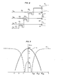
- FIG. 1 diagrammatically illustrates a satellite communication system for providing both an area coverage beam and a plurality of spot coverage beams between the satellite and the associated ground receiver stations;
- FIG. 2 illustrates an arrangement according to the present invention to effect interference cancellation of the area coverage beam at each of the spot coverage receiver stations;
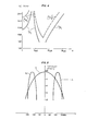
- FIG. 3 is a curve illustrating the antenna pattern of a spot coverage beam and a modified area coverage beam in the area of a spot coverage ground station according to the present invention;
- FIG. 4 is a curve illustrating the Signal-to-Interference ratio at the ground stations between a spot coverage beam and the modified area coverage beam in accordance with the arrangement of FIG. 2;
- FIG. 5 is a curve illustrating the power spectrum of a 4φ- PSK signals for a 300 Mbauds spot beam and two 75 Mbauds area beams in accordance to the present invention.
- In FIG. 1, a satellite communication system is illustrated wherein the present invention is especially useful to permit the concurrent transmission from a
satellite 10 of both anarea coverage beam 12 and a plurality of spot coverage beams of which, for example, threebeams 14a, 14b and 14c are shown with all beams being able to use the same frequency spectrum.Spot coverage beams 14a, 14b and 14c are shown radiating fromantennas respective ground areas traffic ground stations Area coverage beam 12 is shown radiating from anantenna 13 and directed at aground area 18 which includes both theground areas traffic ground stations 17a-17c communicates withsatellite 10 via aseparate spot beam 14a-14c, respectively, while the low traffic ground stations 19a-19d communicate . withsatellite 10 via commonarea coverage beam 12 using any suitable technique to assure that a particular message will be processed by only the appropriate one of stations 19a-19d. Such arrangement permits low traffic ground stations 19a-19d to communicate withsatellite 10 under conditions where it is not advantageous to connect a low traffic ground station 19 to a nearby one of hightraffic ground stations 17a-17c. - It can be seen from FIG. 1 that when
area coverage beam 12 andspot coverage beams 14a-14c are transmitted concurrently and use the same frequency spectrum that each ofground stations 17a-17c will receive both the associated one ofspot coverage beams 14a-14c andarea coverage beam 12 since these beams emmanate from approximately the same point and most probably the same antenna rather than separate antennas as shown in FIG. 1. Under such conditions the use of prior art arrangements such as, for example, side lobe suppression arrangements to select a wave received from a particular direction over waves received from other directions is not feasible. - The concurrent transmission of
area coverage beam 12 and a plurality ofspot coverage beams 14a-14c using the same frequency spectrum can be effected in accordance with the present invention by the arrangement shown in FIG. 2. For purposes of explanation, S represents the signal intended for a particularspot beam antenna 15 with a field pattern Es(θ). More particularly, signals Ssa, Ssb and Ssc propagate inwaveguide respective antennas respective ground stations 17a-17c viaspot coverage beams 14a, 14b and 14c, respectively. The field pattern Es(o) for each of thespot coverage beams 14 is assumed to be of Gaussian shape as, for example, in the main lobe of a paraboloid fed by a corrugated feedhorn, and is given by:
spot coverage beam 14. Additionally, SA represents the signal intended forarea coverage beams 12 and is shown propagating in waveguide 21d toantenna 13 for radiation to ground stations 19 viaarea coverage beam 12 which has a field pattern EA(θ) which is given by
area coverage beam 12. - Since EA(θ) represents the field pattern over
area 18 of FIG. 1, it is desirable to produce a "hole" in EA(θ) in theareas 16a-16c where thespot coverage beams 14a-14c exist such that EA does not interfere with each of the Es patterns. In accordance with the present invention, interference between the signal SA transmitted viaarea coverage beam 12 and each of signals Ssa, Ssb and Ssc transmitted viaspot coverage beams 14a, 14b and 14c, respectively, is substantially reduced at each of the spot beam ground stations 17 by coupling a portion of the area coverage signal, SA, propagating in waveguide 21d, into each of the spot coverage signals S Ssb and Ssc propagating in waveguides 21a-21c, respectively, using respectivedirectional couplers couplers 22a-22c should preferably have a negative coupling coefficient of approximately between one and two times the value of
area beam 12 and one ofspot beams 14a-14c in the vicinity of the associated spot beam ground station 17 then becomes


spot coverage beam 14 remains unchanged when received at associated area 16 whereas thearea coverage beam 12 is significantly reduced in the spot coverage beam region 16. - If it is assumed that 4φ-PSK modulation of the same baud rate is used in both beams and that the Effective Instantaneous Radiated Power (EIRP) at beam peaks are the same, i.e., < EA(O)SA 2> = < Es(O)s 2>, the signal to interference ratio (S/I) at the ground defined by PA/ p s or Ps/PA is shown in FIG. 4 by a solid line, where PA = received power of SA ( EA(θ)[1-1.21


- If advantage is taken of the spectrum shape of the 4φ-PSK signal, the blackout region can be reduced or the S/I may be increased. For example, the capacity of the area coverage beam can be reduced by a factor of two and the modulations can be placed at the edges of the allocated 500 MHz bandwidth of the satellite downlink. The power spectrums of a 300 Mbauds spot coverage peam and two 75 Mbauds area beams are shown in FIG. 5. It should be noted that a ground station 19, intended to receive the
area coverage beam 12, will have a receiving filter having characteristics which follow either spectrum A1 or A2. Therefore, the received interference power of SS is reduced by about 6 dB due to this offsetting of modulation spectrum. Similarly, a ground station 17 intended to receive Ss will have a receiving filter having characteristics which follow spectrum S in FIG. 5. The received power of SA is reduced by about 9 dB compared to that of S . - Taking into account both the S/I improvement obtained by spectrum offsetting (FIG. 5) and the antenna pattern discrim- ination, the resultant (Ps/PA)' and (PA/Ps)' are shown by a dashed line in FIG. 4.
- In FIG. 4 it can be seen that the blackout region is reduced using spectrum offsetting and antenna pattern discrimination. Again for S/I > 14 dB, the regions for (Ps/PA)' and (PA/Ps)' becomes:


Claims (7)

Applications Claiming Priority (2)
| Application Number | Priority Date | Filing Date | Title |
|---|---|---|---|
| US05/803,151 US4145658A (en) | 1977-06-03 | 1977-06-03 | Method and apparatus for cancelling interference between area coverage and spot coverage antenna beams |
| US803151 | 1977-06-03 |
Publications (2)
| Publication Number | Publication Date |
|---|---|
| EP0000038A1 true EP0000038A1 (en) | 1978-12-20 |
| EP0000038B1 EP0000038B1 (en) | 1981-10-14 |
Family
ID=25185701
Family Applications (1)
| Application Number | Title | Priority Date | Filing Date |
|---|---|---|---|
| EP78100062A Expired EP0000038B1 (en) | 1977-06-03 | 1978-06-01 | Method and apparatus for cancelling interference between area coverage and spot coverage antenna beams |
Country Status (5)
| Country | Link |
|---|---|
| US (1) | US4145658A (en) |
| EP (1) | EP0000038B1 (en) |
| JP (1) | JPS542613A (en) |
| CA (1) | CA1105091A (en) |
| DE (1) | DE2861149D1 (en) |
Cited By (4)
| Publication number | Priority date | Publication date | Assignee | Title |
|---|---|---|---|---|
| AU607738B2 (en) * | 1986-12-23 | 1991-03-14 | Messerschmitt-Bolkow-Blohm Gmbh | Process for data transmission by means of a geo-stationary satellite and at least one sub-satellite |
| EP0578075A2 (en) * | 1992-07-06 | 1994-01-12 | Motorola, Inc. | Communication system employing spectrum reuse on a spherical surface |
| EP1770877A2 (en) * | 1997-10-17 | 2007-04-04 | The Boeing Company | Non-uniform multi-beam satellite communications system and method |
| EP2782266A3 (en) * | 2013-03-19 | 2015-03-11 | Delphi Technologies, Inc. | Satellite communication system using hierarchical modulation to transmit a plurality of modulated signals of high and low priority |
Families Citing this family (19)
| Publication number | Priority date | Publication date | Assignee | Title |
|---|---|---|---|---|
| US4379398A (en) * | 1980-06-12 | 1983-04-12 | Kabushiki Kaisha Kobe Seiko Sho | Pull-back type indirect extrusion press |
| US4450582A (en) * | 1981-09-14 | 1984-05-22 | Vitalink Communications Corporation | Method and apparatus for increasing the capacity of a satellite transponder by reuse of bandwidth |
| JPH067836A (en) * | 1984-08-22 | 1994-01-18 | Richard J Blanyer | Combined wire rod, composite cable and those preparations |
| US4827268A (en) * | 1986-08-14 | 1989-05-02 | Hughes Aircraft Company | Beam-forming network |
| US4823341A (en) * | 1986-08-14 | 1989-04-18 | Hughes Aircraft Company | Satellite communications system having frequency addressable high gain downlink beams |
| US4862721A (en) * | 1988-02-16 | 1989-09-05 | Hydramet American, Inc. | Multiple cylinder extrusion apparatus and method |
| US5121503A (en) * | 1989-11-06 | 1992-06-09 | Motorola, Inc. | Satellite signaling system having a signal beam with a variable beam area |
| US5239668A (en) * | 1989-11-06 | 1993-08-24 | Motorola, Inc. | Satellite signalling system |
| CA2067809A1 (en) * | 1989-11-06 | 1991-05-07 | Walter Lee Davis | Satellite signalling system having a signal beam with a variable beam area |
| JP2684119B2 (en) * | 1989-12-14 | 1997-12-03 | モトローラ・インコーポレーテッド | Paging communication device and method |
| US5642358A (en) * | 1994-04-08 | 1997-06-24 | Ericsson Inc. | Multiple beamwidth phased array |
| US5745084A (en) * | 1994-06-17 | 1998-04-28 | Lusignan; Bruce B. | Very small aperture terminal & antenna for use therein |
| TW274170B (en) * | 1994-06-17 | 1996-04-11 | Terrastar Inc | Satellite communication system, receiving antenna & components for use therein |
| US5678442A (en) * | 1995-06-27 | 1997-10-21 | Ube Industries, Ltd. | Extruder |
| DE69608464T2 (en) * | 1995-12-07 | 2001-01-25 | Vistar Telecomm Inc | METHOD FOR IMPROVING THE EFFICIENCY OF USING A RADIO CHANNEL IN OVERLAPPING COVERAGE ZONES |
| US6711398B1 (en) * | 2000-04-19 | 2004-03-23 | Hughes Electronics Corporation | Radio signal broadcast system and method |
| US7366463B1 (en) * | 2000-05-05 | 2008-04-29 | The Directv Group, Inc. | Military UHF and commercial Geo-mobile system combination for radio signal relay |
| US6642883B2 (en) * | 2001-08-30 | 2003-11-04 | Lockheed Martin Corporation | Multi-beam antenna with interference cancellation network |
| US20110148706A1 (en) * | 2009-12-18 | 2011-06-23 | Electronics And Telecommunications Research Institute | Antenna with controlled sidelobe characteristics |
Citations (2)
| Publication number | Priority date | Publication date | Assignee | Title |
|---|---|---|---|---|
| US3325816A (en) * | 1963-07-29 | 1967-06-13 | Marconi Co Ltd | Sidelobe suppressing antenna system comprising directional coupler and phase controlmeans for beam shaping |
| US3511936A (en) * | 1967-05-26 | 1970-05-12 | Bell Telephone Labor Inc | Multiply orthogonal system for transmitting data signals through frequency overlapping channels |
Family Cites Families (11)
| Publication number | Priority date | Publication date | Assignee | Title |
|---|---|---|---|---|
| US2520184A (en) * | 1941-11-08 | 1950-08-29 | Int Standard Electric Corp | Electrical wave signaling system |
| US3094695A (en) * | 1960-03-23 | 1963-06-18 | Sperry Rand Corp | Antenna side lobe suppression system |
| US3369235A (en) * | 1966-02-08 | 1968-02-13 | Gorham Corp | Directionally selective energy receiving system |
| USRE27478E (en) | 1966-08-05 | 1972-09-19 | Prior art | |
| US3406401A (en) * | 1966-08-25 | 1968-10-15 | Bell Telephone Labor Inc | Communication satellite system |
| US3541553A (en) * | 1968-03-27 | 1970-11-17 | Rca Corp | Satellite communications systems |
| US3710255A (en) * | 1969-03-21 | 1973-01-09 | Raytheon Co | Satellite communication system |
| US3711855A (en) * | 1969-10-15 | 1973-01-16 | Communications Satellite Corp | Satellite on-board switching utilizing space-division and spot beam antennas |
| US3673497A (en) * | 1970-10-28 | 1972-06-27 | Peter V Gureckis | Underground radio communication system for roadways |
| US3696429A (en) * | 1971-05-24 | 1972-10-03 | Cutler Hammer Inc | Signal cancellation system |
| US3987444A (en) * | 1974-08-12 | 1976-10-19 | Hazeltine Corporation | Interference rejection system for multi-beam antenna having single control loop |
-
1977
- 1977-06-03 US US05/803,151 patent/US4145658A/en not_active Expired - Lifetime
-
1978
- 1978-05-11 CA CA303,121A patent/CA1105091A/en not_active Expired
- 1978-06-01 DE DE7878100062T patent/DE2861149D1/en not_active Expired
- 1978-06-01 EP EP78100062A patent/EP0000038B1/en not_active Expired
- 1978-06-02 JP JP6585878A patent/JPS542613A/en active Pending
Patent Citations (2)
| Publication number | Priority date | Publication date | Assignee | Title |
|---|---|---|---|---|
| US3325816A (en) * | 1963-07-29 | 1967-06-13 | Marconi Co Ltd | Sidelobe suppressing antenna system comprising directional coupler and phase controlmeans for beam shaping |
| US3511936A (en) * | 1967-05-26 | 1970-05-12 | Bell Telephone Labor Inc | Multiply orthogonal system for transmitting data signals through frequency overlapping channels |
Non-Patent Citations (4)
| Title |
|---|
| COLLOQUE INTERNATIONAL L'ESPACE ET LA COMMUNICATION, Chiron, 1971, Paris, H. KABISCH et al. "Study of a possible regional telecommunication satellite system for Europe", pages 279 to 292 * |
| IEEE INTERNATIONAL CONFERENCE ON COMMUNICATIONS, (Chicago, June 12-15, 1977) New York, D.O. REUDINK et al. "Spectral reuse in 12 GHz satellite communicationsytems", pages 37.5-32 to 37.5-35 * |
| PROCEEDINGS OF THE IEEE, vol. 65, nr. 3, March 1977, New York, L.J. RICARDI "Communication satellite antennas", pages 356 to 369 * |
| WESCON TECHNICAL PAPERS, vol. 19, 1975 (San Francisco, Sept.16-19,1975) New York, COL. H. WYNE & D.E. KENDALL "Defense satellite communication system in the1980s.", Paper 32/5, pages 1 to 5 * |
Cited By (7)
| Publication number | Priority date | Publication date | Assignee | Title |
|---|---|---|---|---|
| AU607738B2 (en) * | 1986-12-23 | 1991-03-14 | Messerschmitt-Bolkow-Blohm Gmbh | Process for data transmission by means of a geo-stationary satellite and at least one sub-satellite |
| EP0578075A2 (en) * | 1992-07-06 | 1994-01-12 | Motorola, Inc. | Communication system employing spectrum reuse on a spherical surface |
| EP0578075A3 (en) * | 1992-07-06 | 1994-05-11 | Motorola Inc | Communication system employing spectrum reuse on a spherical surface |
| EP1770877A2 (en) * | 1997-10-17 | 2007-04-04 | The Boeing Company | Non-uniform multi-beam satellite communications system and method |
| EP1770877A3 (en) * | 1997-10-17 | 2008-08-27 | The Boeing Company | Non-uniform multi-beam satellite communications system and method |
| EP2782266A3 (en) * | 2013-03-19 | 2015-03-11 | Delphi Technologies, Inc. | Satellite communication system using hierarchical modulation to transmit a plurality of modulated signals of high and low priority |
| US9042809B2 (en) | 2013-03-19 | 2015-05-26 | Delphi Technologies, Inc. | Satellite communication having distinct low priority information broadcast into adjacent sub-regions |
Also Published As
| Publication number | Publication date |
|---|---|
| EP0000038B1 (en) | 1981-10-14 |
| DE2861149D1 (en) | 1981-12-24 |
| CA1105091A (en) | 1981-07-14 |
| US4145658A (en) | 1979-03-20 |
| JPS542613A (en) | 1979-01-10 |
Similar Documents
| Publication | Publication Date | Title |
|---|---|---|
| EP0000038A1 (en) | Method and apparatus for cancelling interference between area coverage and spot coverage antenna beams | |
| EP0818059B1 (en) | Wide antenna lobe | |
| US5691978A (en) | Self-cancelling full-duplex RF communication system | |
| USRE44173E1 (en) | Method for improving RF spectrum efficiency with repeater backhauls | |
| EP1566000A1 (en) | System and method for sharing uplink bandwidth among satellites in a common orbital slot | |
| US6404385B1 (en) | Telecommunication system antenna and method for transmitting and receiving using the antenna | |
| WO2006019896A2 (en) | Satellite ground station antenna with wide field of view and nulling pattern | |
| US20030003917A1 (en) | Wireless communication system, apparatus and method for providing wireless communication within a building structure | |
| US6374104B1 (en) | Frequency and polarization allocation for satellite telecommunication systems | |
| CN117178526A (en) | Passive intermodulation interference optimized antenna configuration | |
| EP1900112B1 (en) | A point-to-point telecommunications system | |
| US4933682A (en) | Point to point microwave communication service antenna pattern with anull in an interering direction | |
| US10355772B2 (en) | Combined satellite and terrestrial communication system for terminals located on a vehicle such as an aircraft using a common set of frequencies | |
| US4535476A (en) | Offset geometry, interference canceling receiver | |
| JP2784147B2 (en) | Antenna shared circuit | |
| JPS59161940A (en) | Control system of transmission power for satellite communication | |
| CA2371693A1 (en) | Synchronization of broadcast facilities via satellite and/or microwave link | |
| JPH02174321A (en) | Transmitter-receiver using polarized wave in common for mobile station of mobile body satellite communication | |
| KR100307875B1 (en) | Mobile communication relay system using a circularly polarized wave | |
| US20180375569A1 (en) | Method of telecommunication in a system with multi-spot geographical coverage, corresponding terrestrial station and relay device | |
| JPH0126212B2 (en) | ||
| JP3053506B2 (en) | Satellite communication system | |
| Patan et al. | A Research Perspective Review on Microwave Communications-The Fundamentals, Techniques, and Technologies Uniting the Wireless World | |
| JPS6292630A (en) | Radio zone constitution system in mobile communication | |
| JP2003332962A (en) | Satellite broadcast signal retransmission system |
Legal Events
| Date | Code | Title | Description |
|---|---|---|---|
| PUAI | Public reference made under article 153(3) epc to a published international application that has entered the european phase |
Free format text: ORIGINAL CODE: 0009012 |
|
| AK | Designated contracting states |
Kind code of ref document: A1 Designated state(s): BE DE FR GB NL SE |
|
| 17P | Request for examination filed | ||
| GRAA | (expected) grant |
Free format text: ORIGINAL CODE: 0009210 |
|
| AK | Designated contracting states |
Kind code of ref document: B1 Designated state(s): BE DE FR GB NL SE |
|
| REF | Corresponds to: |
Ref document number: 2861149 Country of ref document: DE Date of ref document: 19811224 |
|
| PGFP | Annual fee paid to national office [announced via postgrant information from national office to epo] |
Ref country code: SE Payment date: 19831231 Year of fee payment: 7 |
|
| PGFP | Annual fee paid to national office [announced via postgrant information from national office to epo] |
Ref country code: DE Payment date: 19840430 Year of fee payment: 7 |
|
| PGFP | Annual fee paid to national office [announced via postgrant information from national office to epo] |
Ref country code: FR Payment date: 19840503 Year of fee payment: 7 |
|
| PGFP | Annual fee paid to national office [announced via postgrant information from national office to epo] |
Ref country code: BE Payment date: 19840630 Year of fee payment: 7 |
|
| PG25 | Lapsed in a contracting state [announced via postgrant information from national office to epo] |
Ref country code: SE Effective date: 19850602 |
|
| PGFP | Annual fee paid to national office [announced via postgrant information from national office to epo] |
Ref country code: NL Payment date: 19850630 Year of fee payment: 8 |
|
| PG25 | Lapsed in a contracting state [announced via postgrant information from national office to epo] |
Ref country code: BE Effective date: 19860630 |
|
| BERE | Be: lapsed |
Owner name: WESTERN ELECTRIC CY INC. Effective date: 19860630 |
|
| PG25 | Lapsed in a contracting state [announced via postgrant information from national office to epo] |
Ref country code: NL Effective date: 19870101 |
|
| NLV4 | Nl: lapsed or anulled due to non-payment of the annual fee | ||
| PG25 | Lapsed in a contracting state [announced via postgrant information from national office to epo] |
Ref country code: FR Free format text: LAPSE BECAUSE OF NON-PAYMENT OF DUE FEES Effective date: 19870227 |
|
| PG25 | Lapsed in a contracting state [announced via postgrant information from national office to epo] |
Ref country code: DE Effective date: 19870303 |
|
| GBPC | Gb: european patent ceased through non-payment of renewal fee | ||
| REG | Reference to a national code |
Ref country code: FR Ref legal event code: ST |
|
| PG25 | Lapsed in a contracting state [announced via postgrant information from national office to epo] |
Ref country code: GB Effective date: 19881117 |
|
| EUG | Se: european patent has lapsed |
Ref document number: 78100062.5 Effective date: 19860728 |
|
| PLBE | No opposition filed within time limit |
Free format text: ORIGINAL CODE: 0009261 |
|
| STAA | Information on the status of an ep patent application or granted ep patent |
Free format text: STATUS: NO OPPOSITION FILED WITHIN TIME LIMIT |