DE69917577T2 - Differential oil pressure control unit and method - Google Patents
Differential oil pressure control unit and method Download PDFInfo
- Publication number
- DE69917577T2 DE69917577T2 DE69917577T DE69917577T DE69917577T2 DE 69917577 T2 DE69917577 T2 DE 69917577T2 DE 69917577 T DE69917577 T DE 69917577T DE 69917577 T DE69917577 T DE 69917577T DE 69917577 T2 DE69917577 T2 DE 69917577T2
- Authority
- DE
- Germany
- Prior art keywords
- oil condition
- microcontroller
- signal
- oil
- sensor
- Prior art date
- Legal status (The legal status is an assumption and is not a legal conclusion. Google has not performed a legal analysis and makes no representation as to the accuracy of the status listed.)
- Expired - Lifetime
Links
Classifications
-
- G—PHYSICS
- G05—CONTROLLING; REGULATING
- G05B—CONTROL OR REGULATING SYSTEMS IN GENERAL; FUNCTIONAL ELEMENTS OF SUCH SYSTEMS; MONITORING OR TESTING ARRANGEMENTS FOR SUCH SYSTEMS OR ELEMENTS
- G05B23/00—Testing or monitoring of control systems or parts thereof
- G05B23/02—Electric testing or monitoring
- G05B23/0205—Electric testing or monitoring by means of a monitoring system capable of detecting and responding to faults
- G05B23/0259—Electric testing or monitoring by means of a monitoring system capable of detecting and responding to faults characterized by the response to fault detection
- G05B23/0286—Modifications to the monitored process, e.g. stopping operation or adapting control
- G05B23/0291—Switching into safety or degraded mode, e.g. protection and supervision after failure
-
- G—PHYSICS
- G05—CONTROLLING; REGULATING
- G05B—CONTROL OR REGULATING SYSTEMS IN GENERAL; FUNCTIONAL ELEMENTS OF SUCH SYSTEMS; MONITORING OR TESTING ARRANGEMENTS FOR SUCH SYSTEMS OR ELEMENTS
- G05B9/00—Safety arrangements
- G05B9/02—Safety arrangements electric
Landscapes
- Physics & Mathematics (AREA)
- General Physics & Mathematics (AREA)
- Engineering & Computer Science (AREA)
- Automation & Control Theory (AREA)
- Control Of Positive-Displacement Pumps (AREA)
Description
Hintergrund der ErfindungBackground of the invention
1. Gebiet der Erfindung1. Field of the invention
Diese Erfindung bezieht sich allgemein auf Kompressoren, die z. B. in Klima- und Kühlanlagen verwendet werden, und insbesondere auf eine Steuerung zur Erfassung unzulänglicher Öldruckzustände in einem Kompressor sowie zum Schutz des Kompressors vor einer Beschädigung durch solche Zustände.These The invention relates generally to compressors, the z. In Air conditioning and cooling systems be used, and in particular to a control for detection Inadequate oil pressure conditions in a compressor and to protect the compressor from damage by such conditions.
2. Kurzbeschreibung des Standes der Technik2. Short description of the prior art
Die Verwendung von Elektronik zum Steuern und Erfassen des Öldrucks für Kompressoren ist bekannt. Herkömmliche Steuerungen verwenden typischerweise die Zeit bzw. den Tastgrad von guten Ölzuständen im Vergleich zu schlechten Ölzuständen, um Kompressoroperationen zu stoppen. Die Ölsensorsteuerungen des Standes der Technik verwenden eine diskrete Elektronik und einen normalerweise offenen Öldruckschalter. Jedes Mal, wenn ein schlechter Ölzustand vorhanden ist, wird der Druckschalter geöffnet und die diskrete Elektronik beginnt, die Zeit zu messen. Wenn die Zeit zwei Minuten erreicht, wird ein magnetisches Einklinkrelais erregt (d. h. das Relais wird eingeklinkt), das seinerseits die Leistungszufuhr zum Kompressor unterbricht. Dieses System weist das Merkmal auf, dass die Steuerung nach zwei Minuten aussetzt, wenn der Druckschalter getrennt wird. Die Funktion der Steuerung ist es, den Kompressor vor einem Ausfall der Schmierung zu schützen. Dies ist eine zeitlich gewichtete Mittelwertmessung, um störende Auslösungen (durch Zustände wie das Abtauen, wo flüssiges Kühlmittel kurzzeitig in den Kompressor zurückströmen kann) zu vermeiden. Um einen zeitlich gewichteten Mittelwert zu implementieren, muss die Steuerung die akkumulierte Zeit schlechten Öls während kurzer Leistungsausfälle (bis zu 2 Minuten) behalten. Dies bedeutet, dass die Spannung in der Steuerung während dieser Unterbrechungen aufrechterhalten werden muss. Wenn die Leistung unterbrochen wird, öffnet der Druckschalter, sobald der Kompressor stoppt (der Öldruck geht verloren), falls der Druckschalter eine normalerweise offene Vorrichtung ist. Dieser offene Schalter beschränkt den Leistungsverlust, was wiederum während der Leistungsunterbrechung länger Spannung an der Steuerung aufrechterhält. Dieses System des Standes der Technik ist für die Aufgabe ausreichend, weist jedoch viele Unzulänglichkeiten auf. Zunächst verwendet der Öldruckschalter ein Magnetschiffchen, das sich bewegt, wenn sich der Druck ändert, sowie einen Reed-Schalter. Wegen steigendem Öldruck bewegt sich das Magnetschiffchen zum Reed-Schalter, was wiederum bewirkt, dass der Reed-Schalter schließt. Der Öldruckschalter könnte sehr viel kleiner und weniger kostspielig hergestellt werden, wenn der Druck das Magnetschiffchen von dem Reed-Schalter weg bewegen würde, was aber bedeutet, dass der Öldruckschalter normalerweise geschlossen ist. Unter Verwendung der Steuerung des Standes der Technik ist die Aufrechterhaltung der Spannung während Leistungsunterbrechungen mit einem normalerweise geschlossenen Druckschalter (ohne eine aufwändige Signalpufferung) unmöglich. Abgesehen davon erfasst die Steuerung des Standes der Technik nicht, ob die Leitungen zum Sensor miteinander kurzgeschlossen sind (tatsächlich fährt die Steuerung fort, zu ermöglichen, dass der Kompressor ständig in diesem Zustand betrieben wird). Die Verwendung diskreter Elektronik hat ferner den Nachteil, dass die Auslösezeit nicht leicht geändert werden kann (d. h. die Leiterplatte muss geändert werden). Fehleranzeigeleuchten können nicht mit der Steuerung des Standes der Technik verwendet werden, da eine LED eine kontinuierliche Stromentnahme an der Leistungsquelle bilden würde. Dies würde ebenso zu einem Zeitverlust während einer Leistungsunterbrechung führen. Schließlich kann diskrete Elektronik Rauschsignale nicht leicht aus den Sensorsignalen filtern und erfordert in verrauschten Umgebungen die Verwendung kostspieliger geschirmter Kabel.The Use of electronics to control and sense oil pressure for compressors is known. conventional Controls typically use the time or duty cycle of good oil conditions in the Compared to bad oil conditions, um Stop compressor operations. The oil sensor controls of the state The technique uses discrete electronics and one normally open oil pressure switch. Every time a bad oil condition is present, the pressure switch is opened and the discrete electronics begins to measure the time. When the time reaches two minutes, a magnetic latch relay is energized (i.e., the relay becomes latched in), which in turn supplies the power to the compressor interrupts. This system has the feature that the control after two minutes, when the pressure switch is disconnected. The function of the controller is to prevent the compressor from failure to protect the lubrication. This is a time-weighted average measurement to avoid disturbing tripping (by conditions like defrosting, where liquid coolant can briefly flow back into the compressor) to avoid. To implement a time weighted average, The controller needs the accumulated time of bad oil during a short time power outages (up to 2 minutes). This means that the tension in the controller during these interruptions must be maintained. If the power is interrupted, the opens Pressure switch as soon as the compressor stops (the oil pressure goes off lost), if the pressure switch is a normally open device is. This open switch limits the power loss, what again while the power interruption longer Maintains voltage to the controller. This system of the state the technology is for the task is sufficient, but has many shortcomings on. First uses the oil pressure switch a magnetic boat that moves when the pressure changes, as well a reed switch. Because of increasing oil pressure the magnetic shuttle moves to the reed switch, which in turn causes the reed switch to close. The oil pressure switch could be very much smaller and less expensive to be made when the Pressure the magnetic shuttle would move away from the reed switch but means that the oil pressure switch normally closed. Using the control of the The prior art is maintaining the voltage during power interruptions with a normally closed pressure switch (without complex signal buffering) impossible. Besides, the control of the prior art does not capture whether the lines to the sensor are shorted together (in fact, the Control continues to allow that the compressor constantly operated in this state). The use of discrete electronics also has the disadvantage that the tripping time is not easily changed can (that is, the circuit board must be changed). Fault indicator lights can can not be used with the control of the prior art since a LED is a continuous current drain on the power source would form. This would as well at a loss of time during lead to a power outage. After all Discrete electronics can not easily emit noise signals from the sensor signals filter and require the use of more expensive in noisy environments shielded cable.
Zusammenfassung der ErfindungSummary the invention
Es ist eine Aufgabe der vorliegenden Erfindung, eine Steuerung zu schaffen, die die oben angemerkten Beschränkungen des Standes der Technik überwindet.It an object of the present invention is to provide a controller the limitations noted above of the prior art overcomes.
Kurz
erklärt,
bezieht sich die vorliegende Erfindung auf eine vereinfachte, weniger
kostspielige Steuerung mit vielen zusätzlichen Merkmalen. Eine in Übereinstimmung
mit der Erfindung hergestellte Steuerung ist in dem Stromlaufplan
von
In einer Ausführungsform der Erfindung wird der Steuerung das Stoßmerkmal hinzugefügt, um ein Systemfüllstandsproblem zu lösen. Wenn ein halbhermetischer Kompressor an einen Kunden ausgeliefert wird, wird er im Allgemeinen im Voraus mit Kühlmittel gefüllt, wobei eine Menge des Kühlmittels in flüssiger Form vorliegt. Falls der Kompressor versucht, sehr lange mit dem vorhandenen flüssigen Kühlmittel zu arbeiten, kann an dem Kompressor ein Schaden hervorgerufen werden. Wenn der Kompressor erst einmal installiert ist, schaltet der Servicetechniker den Kompressor für eine sehr kurze Dauer (1 bis 5 Sekunden) an und schaltet darauf die Einheit schnell ab. Dies drückt das Kühlmittel aus dem Kompressor und in das System. Dieser Prozess wird als "Stoß" des Kompressors bezeichnet. Insbesondere dieser Prozess verläuft sehr unkontrolliert (subjektive Erregungszeiten, die auf der Wahrnehmung des Servicetechnikers beruhen). Eine gut bekannte Eigenschaft einer Ölpumpe besteht darin, dass sie keinen Druck erzeugt, bis sie mit einer Solldrehzahl rotiert. Somit ist jedes Mal, wenn der Kompressor startet, ein schlechter Ölzustand vorhanden, der jedoch lediglich etwa 8 Sekunden dauert. Falls ein normalerweise geschlossener Öldruckschalter verwendet wird, wird der Schalter geschlossen, bis der Motor im Kompressor 60% seiner Enddrehzahl erreicht. Diese physikalische Eigenschaft und die Notwendigkeit für einen STOSS des Kompressors sind kombiniert worden, um ein Merkmal dieser Ausführungsform der Erfindung zu erzeugen. Während der Kompressor startet, prüft die Steuerung zunächst den Status des Druckschalters. Der Schalter sollte für 4 bis 8 Sekunden geschlossen werden, falls die Steuerung einen offenen Schalter (gutes Öl) erfasst, wenn der Kompressor gestartet wird, wobei die Einheit das System abschalten wird, da die einzigen Möglichkeiten, dass dies vorkommen kann, wie folgt sind: der Öldruckschalter ist ausgefallen, die Sensorkabel sind miteinander kurzgeschlossen oder jemand hat versucht, den Druckschalter zu überbrücken. Diese Funktion ist mit dem STOSSmerkmal kombiniert worden.In an embodiment In accordance with the invention, the bumper feature is added to the controller to address a system level problem to solve. When a semi-hermetic compressor is delivered to a customer, it is generally filled in advance with coolant, wherein a lot of the coolant in liquid form is present. If the compressor tries very long with the existing one liquid coolant To work, damage can be caused to the compressor. Once the compressor is installed, the service technician will switch the compressor for a very short duration (1 to 5 seconds) and switches to it the unit quickly. This expresses the coolant from the compressor and into the system. This process is called the "push" of the compressor designated. In particular, this process is very uncontrolled (subjective Excitation times based on the perception of the service technician). A well-known feature of an oil pump is that it does not generate pressure until it rotates at a setpoint speed. Thus, every time the compressor starts, it is a bad oil condition present, but only takes about 8 seconds. If one normally closed oil pressure switch is used, the switch is closed until the motor in Compressor reaches 60% of its final speed. This physical property and the need for a shock of the compressor have been combined to a feature this embodiment to produce the invention. While the compressor starts, checks the controller first the status of the pressure switch. The switch should be for 4 to 8 seconds if the controller is open Switch (good oil) detected when the compressor is started, the unit the System will shut down because the only ways that this happens can, as follows: the oil pressure switch has failed, the sensor cables are shorted together or someone tried to bridge the pressure switch. This feature is with been combined with the SHOCK feature.
Falls der Öldruckschalter beim Starten des Kompressors geöffnet ist, wird zugelassen, dass der Kompressor für 3 bis 4 Sekunden arbeitet, wobei die Einheit abgeschaltet wird, indem das Relais erregt wird. Somit kann ein Servicetechniker die Stoßfunktion durch ein einfaches Kurzschließen zweier Leitungen im Sensorkabel starten. Gleichzeitig auftretende Kabelfehler, Fehler des Öldrucksensors und absichtliche Überbrückungen des Schalters führen dazu, dass der Kompressor nach wenigstens vier Sekunden abgeschaltet wird.If the oil pressure switch opened when starting the compressor is allowed, the compressor works for 3 to 4 seconds, wherein the unit is turned off by the relay is energized. Thus, a service technician can perform the shock function by a simple short of two lines in the sensor cable. At the same time Cable fault, oil pressure sensor failure and deliberate bridging of the Switch lead causing the compressor to shut off after at least four seconds becomes.
Die Verwendung des Mikrocontrollers ermöglicht, dass Softwaretechniken zum Filtern des Öldruckschalter-Eingangs verwendet werden. Da der Öldrucksensor außerdem von einer getrennten Leistungsversorgung mit Leistung versorgt wird, wird ein in den Leitungen der Leistungsversorgung induziertes Rauschen nicht in den Mikro eingegeben. Dies beseitigt den Bedarf an kostspieligen geschirmten Kabeln für die Rauschunempfindlichkeit.The Use of the microcontroller allows for software engineering to filter the oil pressure switch input be used. Since the oil pressure sensor Furthermore powered by a separate power supply, becomes a noise induced in the lines of the power supply not entered into the micro. This eliminates the need for expensive shielded cables for the noise immunity.
Kurzbeschreibung der ZeichnungSummary the drawing
Beschreibung der bevorzugten Ausführungsformendescription of the preferred embodiments
In
Der
Leistungsversorgungs-Abschnitt,
Der
Mikro-/Logik-Abschnitt (
Der Relaisunterabschnitt umfasst R7, Q1, K1, CR6 und die P1-Positionen A, B und C. Das Signal RLAY_OUT von dem Mikro-/Logik-Abschnitt ist mit dem Widerstand R7 (5,1 kΩ) verbunden. Die andere Seite von R7 ist mit der Basis von Transistor Q1 (ein MPSA06) verbunden. R7 stellt den Vorstrom für den Transistor ein. Der Emitter von Q1 ist mit GND verbunden. Der Kollektor von Q1 ist mit der negativen Seite der Spule von K1 verbunden. Die positive Seite der Spule von K1 ist mit RLAY-PWR (von dem Leistungsversorgungs-Abschnitt) verbunden. Die Anode der Diode CR6 ist ebenso mit dem Kollektor von Q1 verbunden. Die Katode von CR6 ist an RLAY_PWR angeschlossen. Mit dieser Schaltungsanordnung beginnt der Transistor Q1, Strom von dem Kollektor zu dem Emitter zu leiten, wenn der Mikrocontroller das Signal RLAY_OUT auf 5 Volt ansteuert. Dies wiederum bewirkt, dass Strom durch die Spule von K1 fließt. Das von dieser Steuerung verwendete Relais ist so beschaffen, dass die normalerweise geschlossenen Kontakte öffnen und die normalerweise offenen Kontakte schließen, wenn für 5 Millisekunden 9 Volt an die Spule angelegt werden. Das verwendete Relais ist außerdem ein magnetischer Einklinktyp. Das bedeutet, wenn die Kontakte den Zustand ändern, dann verbleiben sie in diesem Zustand, bis eine entgegengesetzte Spannung oder ein externer Magnet, der in die Nähe des Relais gebracht wird, auf sie wirkt. In dieser Steuerung wird das letztere Verfahren verwendet. Wenn die Relaisspule wie oben beschrieben erregt wird, wird die Verbindung zwischen dem Signal L und dem Signal M unterbrochen. Es wird eine Verbindung zwischen L und A hergestellt. In einem typischen Kühlsystem ist L an der Wechselspannungs-Leistungsquelle angebracht und M ist an einen Kontaktgeber angeschlossen, der seinerseits den Kompressor ansteuert. Das Signal ist typischerweise mit einer Alarmanzeige wie etwa einer Neonröhre verbunden. Folglich wird ein Alarm angezeigt und der Kompressor wird abgeschaltet, wenn die Steuerung das Relais wegen eines schlechten Öldruckzustands erregt.Of the Relay subsection includes R7, Q1, K1, CR6 and the P1 positions A, B and C. The signal RLAY_OUT from the micro / logic section is with the resistor R7 (5.1 kΩ) connected. The other side of R7 is with the base of transistor Q1 (an MPSA06) connected. R7 adjusts the bias current for the transistor. The emitter of Q1 is connected to GND. The collector of Q1 is connected to the negative side of the coil of K1. The positive Side of the coil of K1 is with RLAY-PWR (from the power supply section) connected. The anode of the CR6 diode is also connected to the collector connected by Q1. The cathode of CR6 is connected to RLAY_PWR. With this circuit arrangement, the transistor Q1 starts current from the collector to the emitter when the microcontroller the signal RLAY_OUT drives at 5 volts. This in turn causes that current flows through the coil of K1. That from this controller used relay is designed so that the normally closed Open contacts and the normally open contacts close when 9 volts for 5 milliseconds the coil will be applied. The relay used is also on magnetic latch type. That means, if the contacts change the state, then remain in this state until an opposite voltage or an external magnet that is brought near the relay, works on them. In this control, the latter method is used. When the relay coil is energized as described above, the Connection between the signal L and the signal M interrupted. A connection between L and A is made. In a typical cooling system L is at the AC power source attached and M is connected to a contactor, in turn activates the compressor. The signal is typically one Alarm indicator connected like a neon tube. Consequently, will an alarm is displayed and the compressor is switched off when the Control energized the relay because of a bad oil pressure condition.
Die Steuerschaltung arbeitet in der folgenden Weise. Jedes Mal, wenn eine Leistung anfänglich an das Steuerschaltungsmodul angelegt wird, werden alle Modulfunktionen zurückgesetzt und es wird ein Selbsttest ausgeführt. Der Mikrocontroller überprüft seine interne Funktionalität sowie die Anwesenheit und den Wert der Netzfrequenzunterbrechung. Während dieser Operation, ist die LED-Anzeige ORANGE. Falls das Modul den Selbsttest besteht, wird die Anzeige in der Farbe ORANGE ausgeblendet, und die normalen Zeitsteuerfunktionen werden begonnen.The Control circuit operates in the following manner. Whenever a performance initially is applied to the control circuit module, all module functions reset and a self-test is performed. The microcontroller checks its internal functionality as well as the presence and the value of the power frequency interruption. While This operation is the LED indicator ORANGE. If the module passes the self-test, the display will show hidden in the color ORANGE, and the normal timing functions are started.
Wenn das Modul den Selbsttest bestanden hat, geht der Mikrocontroller in einen Energiesparmodus über. Er verbleibt in diesem Modus, bis die nächste Netzfrequenzunterbrechung erfolgt (60-mal pro Sekunde bei 60 Hz und 50-mal pro Sekunde bei 50 Hz). Jedes Mal, wenn die Netzfrequenzunterbrechung erfolgt, testet der Mikrocontroller den Druckschaltereingang. Ein niedriges Signal (etwa 0 Volt) an dem Eingang von dem Sensor zeigt einen schlechten Ölzustand an (d. h. einen niedrigen Öldruck). Wenn ein schlechter Ölzustand erfasst wird, wird die LED ROT erleuchtet. Ein hoher Signalpegel (etwa +5 V Gleichspannung) an dem Druckschaltereingang zeigt einen guten Ölzustand an. Wenn ein guter Ölzustand erfasst wird, wird die LED GRÜN erleuchtet. Der Mikroprozessor inkrementiert einen Zähler einmal für jeden schlechten Ölzustand. Dieser gleiche Zählwert wird jedes Mal, wenn ein guter Ölzustand erfasst wird, um einhalb verringert. Diese Zeit ist die akkumulierte Zeit schlechten Öls. Wenn die Zeit schlechten Öls einen Zählwert von 13.200 erreicht (110 Sekunden, multipliziert mit 60 Hz, multipliziert mit 2 Zählungen je Zyklus), setzt die Steuerschaltung das Relais, das den Kontakt M trennt und den Kontakt A erregt. Falls zwischen den Anschlüssen M und 2 ein Überbrückungsleiter installiert ist, wird das Modul abgeschaltet, wenn das Relais gesetzt wird. Das Relais ist ein magnetisch eingeklinktes Relais und bleibt in dem gesetzten Zustand, bis wie unten beschrieben der Rückstellknopf auf der Abdeckung gedrückt wird. Falls die akkumulierte Zeit schlechten Öls einen Zählwert von 13.200 nicht erreicht hat, kehrt der Mikro in den Energiesparmodus zurück, bis die nächste Netzfrequenzunterbrechung erfolgt.If the module has passed the self-test, the microcontroller enters a power-saving mode. It will remain in this mode until the next power line interruption occurs (60 times per second at 60 Hz and 50 times per second at 50 Hz). Each time the grid frequency interrupt occurs, the microcontroller tests the pressure switch input. A low signal (about 0 volts) at the input from the sensor indicates a poor oil condition (ie, a low oil pressure). If a bad oil condition is detected, the RED LED is illuminated. A high signal level (about +5 V DC) at the pressure switch input indicates a good oil condition. When a good oil condition is detected, the LED GREEN is lit. The microprocessor increments a counter once for each bad oil condition. This same count value is decreased by one and a half each time a good oil condition is detected. This time is the accumulated time of bad oil. When the time of bad oil reaches a count of 13,200 (110 seconds multiplied by 60 Hz multiplied by 2 counts per cycle), the control circuit sets the relay which disconnects the contact M and energizes the contact A. If a jumper is installed between terminals M and 2, the module shuts off when the relay is set. The relay is a magnetically latched relay and remains in the set state until the reset button on the cover is pressed as described below. If the accumulated time of bad oil has not reached a count of 13,200, the micro will return to the low power mode until the next power line interruption occurs.
Jedes Mal, wenn eine Leerlaufzeit auftritt (keine Netzfrequenzunterbrechungen oder kein Setzten des Relais), geht das Steuerschaltungsmodul in einen Energiesparmodus über. Dies ermöglicht, dass das Modul kurzzeitige Leistungsunterbrechungen ohne Verlust der akkumulierten Zeit schlechten Öls übersteht. Während eines Leistungsverlusts erhält das Modul die akkumulierte Zeit schlechten Öls für wenigstens 60 Sekunden. Die Zeitsteuerung findet während eines Leistungsverlusts nicht statt (da sie auf der Netzfrequenzunterbrechung beruht) und die LED wird nicht erleuchtet. Die LED und der Öldrucksensor werden von einer getrennten +5-Volt-Gleichspannungsversorgung von dem Mikrocontroller mit Leistung versorgt, wobei somit der Mikrocontroller während des Leistungsverlusts nicht beeinflusst wird.each Time when an idle time occurs (no mains frequency interruptions or not setting the relay), the control circuit module goes into a power saving mode via. This makes possible, that the module short-term power interruptions without loss survives the accumulated time of bad oil. During a power loss receives the module the accumulated time of bad oil for at least 60 seconds. The Time control takes place during loss of power does not take place (as it is due to the power frequency interruption is based) and the LED is not lit. The LED and the oil pressure sensor are powered by a separate + 5 volt DC power supply the microcontroller with power supplied, thus the microcontroller while of power loss is not affected.
Wie
oben in der Beschreibung des Zeitsteuerungsbetriebs angegeben ist,
muss der Zählwert
schlechten Öls
13.200 erreichen, bevor das Relais gesetzt wird. Wie angemerkt wird,
verringert der gute Ölzustand diesen
Zählwert
um eins, während
ein schlechter Ölzustand
diesen Zählwert
um zwei vergrößert. Falls
ein guter Ölzustand
2/3 der Zeit vorhanden ist (das schlechte Öl nimmt das verbleibende 1/3
ein), läuft
daher das Modul (auf der Grundlage einer Zeitbasis von 1 Sekunde)
nie ab. Die in
Die Steuerschaltung verwendet ein magnetisch eingeklinktes Relais. Wenn dieses Relais gesetzt wird, verbleibt es in einem gesetzten Zustand, bis der Rückstellknopf gedrückt wird. In dem Rückstellknopf der Modulabdeckung ist ein Dauermagnet enthalten. Während der Knopf niedergedrückt wird, wird der Mag net in die Nähe des Relais gebracht. Falls das Relais gesetzt ist, bewirkt die magnetische Anziehung des Magneten in dem Rückstellknopf, dass das Relais zurückgesetzt wird (d. h., dass der Kontakt A geöffnet wird und der Kontakt M geschlossen wird). Dies ermöglicht, dass die Steuerschaltung zurückgesetzt wird, wenn keine Leistung für das Modul vorhanden ist.The Control circuit uses a magnetically latched relay. If this relay is set, it remains in a set state, until the reset button depressed becomes. In the reset button The module cover is a permanent magnet included. During the Button depressed becomes, the Mag net in the proximity brought to the relay. If the relay is set, the magnetic causes Attraction of the magnet in the reset button, that reset the relay (that is, the contact A is opened and the contact M is closed). This makes possible, that the control circuit reset will if no power for the module is present.
Wenn die Steuerschaltung eingeschaltet wird und einen guten Ölzustand erfasst, ist es möglich, dass der Kompressor für 4 Sekunden läuft und dass das Relais gesetzt wird, was den Kompressor abschaltet. Es wird angemerkt, dass der Kompressor nie mit einem guten Ölzustand startet. Somit findet ein Abschalten des Kompressors statt, falls ein Kurzschluss in dem Kabel zum Öldrucksensor aufgetreten ist oder falls an dem Modul unerlaubte Änderungen vorgenommen worden sind. Ein Servicetechniker kann folglich die Sensorleitungen miteinander kurzschließen, so dass der Kompressor für eine kurze Zeitdauer anläuft, und den Betrieb des Einklinkrelais prüfen. Kompressoren werden sehr oft im Voraus mit Kühlmittel und Öl gefüllt versendet. Der Servicetechniker muss den Kompressor bedienen (wenn er richtig installiert ist), um das überschüssige Kühlmittel aus dem Kompressor zu stoßen. Die in Übereinstimmung mit der Erfindung hergestellte Steuerschaltung vereinfacht diese Bedienung mit diesem Merkmal.If the control circuit is turned on and a good oil condition recorded, it is possible that the compressor for 4 seconds running and that the relay is set, which shuts off the compressor. It is noted that the compressor never with a good oil condition starts. Thus, a shutdown of the compressor takes place, if a short circuit has occurred in the cable to the oil pressure sensor or if unauthorized changes have been made to the module are. A service technician can therefore connect the sensor lines with each other short-circuit, so the compressor for a short period of time, and check the operation of the latch relay. Compressors become very often in advance with coolant and oil filled sent. The service technician must operate the compressor (if it is installed properly) to remove the excess coolant from the compressor to come across. The in agreement Control circuit made with the invention simplifies this Operation with this feature.
Die Steuerschaltung kann kontinuierlich mit Leistung versorgt werden, indem ein Netzanschluss mit 2 und 120 (oder 240) verbunden wird. Wenn er auf diese Weise verbunden ist, bleibt die LED mit ROT erleuchtet, nachdem das Relais gesetzt ist. Dies ermöglicht eine kontinuierliche Anzeige eines Auslösezustands (in dem der Mikroprozessor fortfährt, einen schlechten Ölzustand und die Zeit dafür zu erfassen, wobei jedoch keine Maßnahme ergriffen werden kann, da das Relais bereits in dem gesetzten Zustand eingeklinkt ist). Falls dieser Verbindungstyp erwünscht ist, muss die Leistung jedes Mal von der Steuerschaltung entfernt werden, wenn das Hauptsteuersystem den Kompressor nicht betreibt.The Control circuit can be continuously powered, by connecting a power connector to 2 and 120 (or 240). When connected in this way, the RED LED stays lit after the relay is set. this makes possible a continuous indication of a trip condition (in which the microprocessor continues a bad oil condition and the time for it but no action can be taken, because the relay is already latched in the set state). If this type of connection is desired is, the power must be removed from the control circuit each time when the main control system is not operating the compressor.
Die
Steuerschaltung ist konstruiert, um sowohl mit dem normalerweise
offenen Sensor S1 als auch mit dem normalerweise geschlossenen Sensor
S2 verwendet zu werden, die, wie jeweils in den
Das oben beschriebene Steuerschaltungsmodul verwendet eine dreifarbige LED-Anzeige, um die verschiedenen Betriebsarten anzuzeigen. Die folgende Tabelle gibt die Bedeutung der verschiedenen Farben an.The The control circuit module described above uses a tri-color LED indicator to to display the different operating modes. The following table indicates the meaning of the different colors.

Der
Ablaufplan von
Falls
der Stoßmodus
in Schritt
Falls
der Druckschalter in Schritt
Die folgenden Komponenten wurden in einem gemäß der Erfindung hergestellten Modul verwendet:The The following components were prepared in a manufactured according to the invention Module uses:

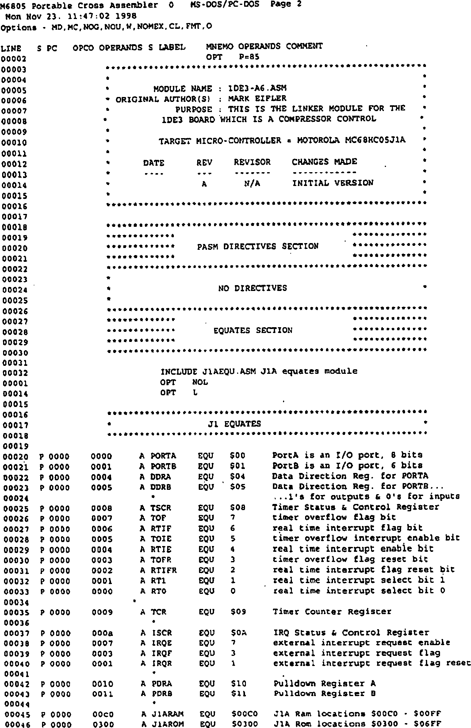
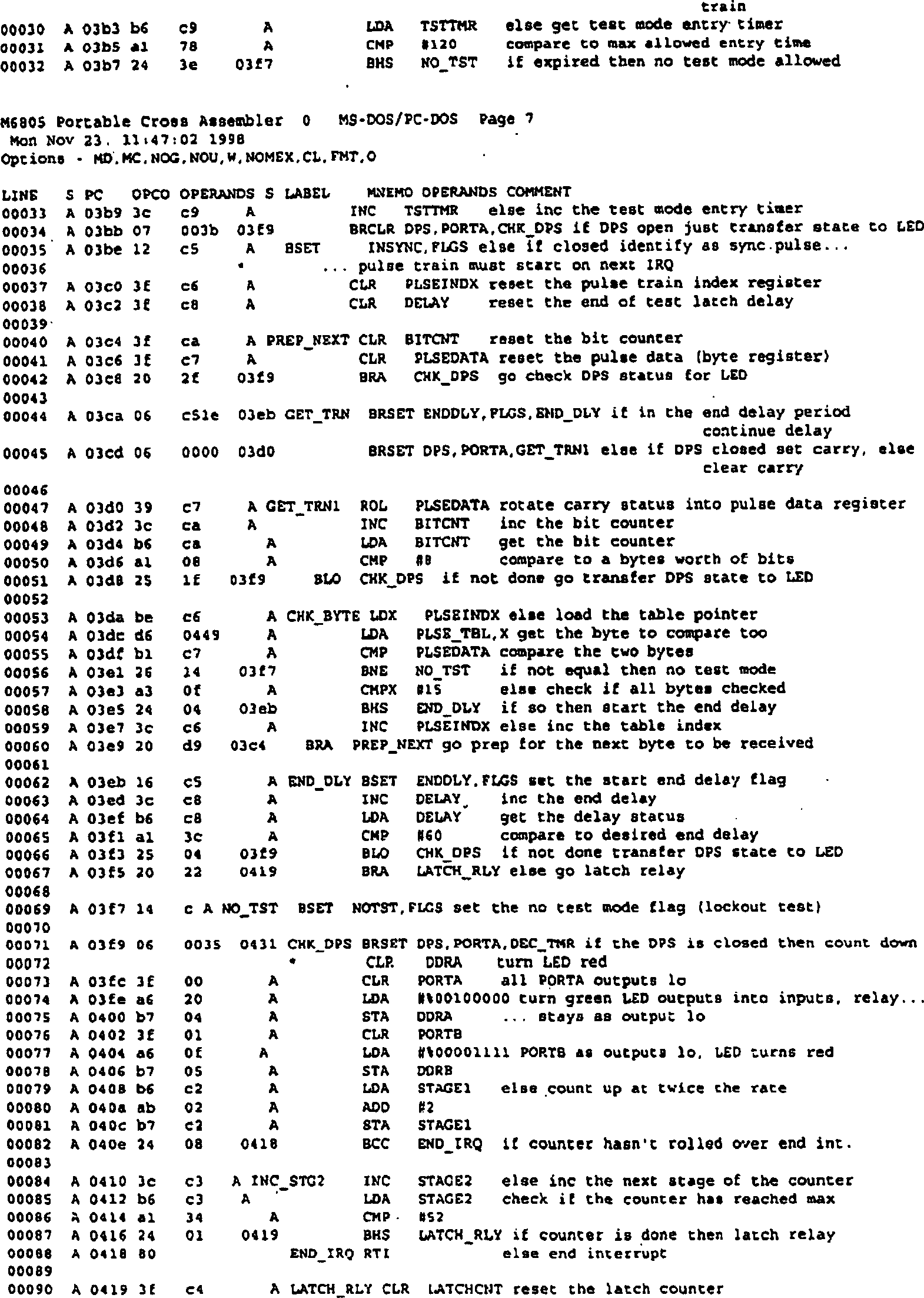
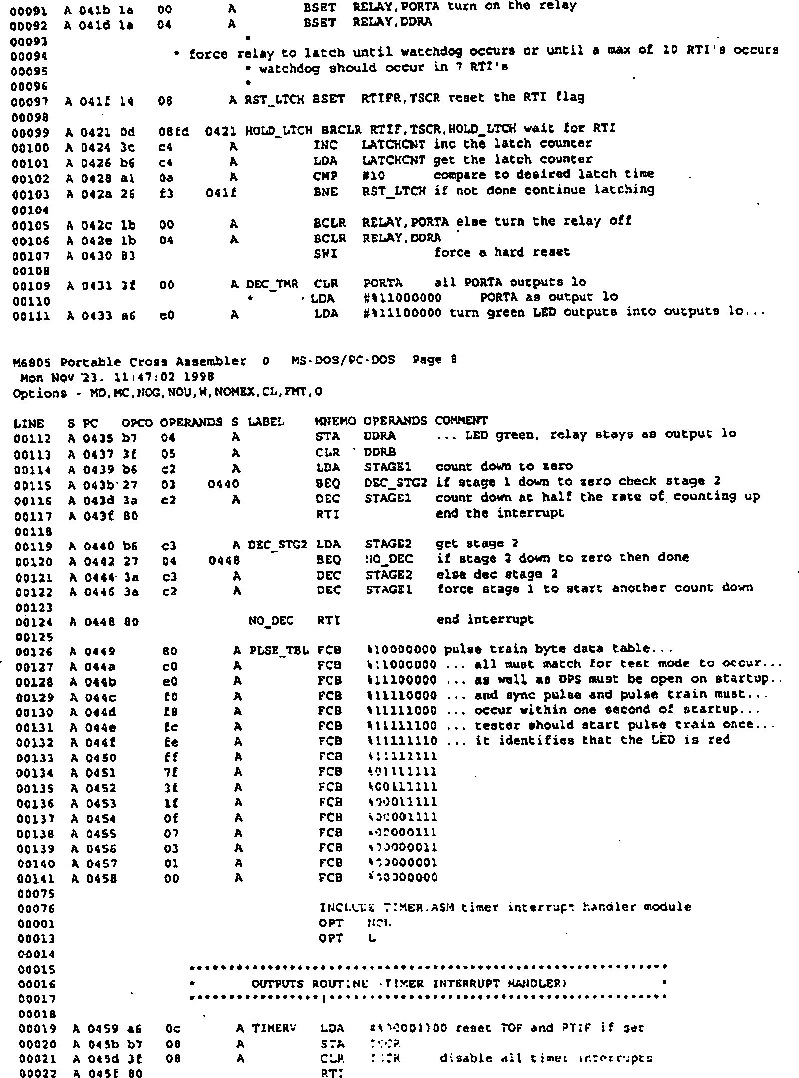
Ein Protokoll der mit dem Mikrocontroller U1 verwendeten Software ist wie folgt gegeben:One Protocol of the software used with the microcontroller U1 given as follows:


Claims (9)
Applications Claiming Priority (2)
| Application Number | Priority Date | Filing Date | Title |
|---|---|---|---|
| US11323598P | 1998-12-21 | 1998-12-21 | |
| US113235P | 1998-12-21 |
Publications (2)
| Publication Number | Publication Date |
|---|---|
| DE69917577D1 DE69917577D1 (en) | 2004-07-01 |
| DE69917577T2 true DE69917577T2 (en) | 2005-06-09 |
Family
ID=22348318
Family Applications (1)
| Application Number | Title | Priority Date | Filing Date |
|---|---|---|---|
| DE69917577T Expired - Lifetime DE69917577T2 (en) | 1998-12-21 | 1999-12-21 | Differential oil pressure control unit and method |
Country Status (3)
| Country | Link |
|---|---|
| US (1) | US6237420B1 (en) |
| EP (1) | EP1014243B1 (en) |
| DE (1) | DE69917577T2 (en) |
Families Citing this family (7)
| Publication number | Priority date | Publication date | Assignee | Title |
|---|---|---|---|---|
| US6753785B2 (en) | 2000-12-13 | 2004-06-22 | Anthony F. Denietolis, Jr. | Oil tank sight glass monitor |
| BE1015717A3 (en) * | 2003-10-15 | 2005-07-05 | Atlas Copco Airpower Nv | Improved water injected screw compressor. |
| US20080041081A1 (en) | 2006-08-15 | 2008-02-21 | Bristol Compressors, Inc. | System and method for compressor capacity modulation in a heat pump |
| US8672642B2 (en) * | 2008-06-29 | 2014-03-18 | Bristol Compressors International, Inc. | System and method for starting a compressor |
| US8601828B2 (en) * | 2009-04-29 | 2013-12-10 | Bristol Compressors International, Inc. | Capacity control systems and methods for a compressor |
| JP6377659B2 (en) * | 2016-03-11 | 2018-08-22 | 株式会社東芝 | Semiconductor device and control method thereof |
| CN107899277B (en) * | 2017-11-18 | 2021-05-04 | 襄垣县树元电器有限公司 | Automatic plate pulling device for water pump receiving plate of filter press |
Family Cites Families (10)
| Publication number | Priority date | Publication date | Assignee | Title |
|---|---|---|---|---|
| US3682574A (en) | 1970-10-06 | 1972-08-08 | Westinghouse Air Brake Co | Low oil pressure control system for compressors |
| US3705499A (en) | 1971-09-23 | 1972-12-12 | Carrier Corp | Oil dilution control |
| US3965692A (en) | 1974-11-15 | 1976-06-29 | Friedrich Refrigerators Inc. | Refrigeration control circuit |
| US5067326A (en) | 1979-07-31 | 1991-11-26 | Alsenz Richard H | Method and apparatus for controlling capacity of a multiple-stage cooling system |
| US4510547A (en) | 1982-11-12 | 1985-04-09 | Johnson Service Company | Multi-purpose compressor controller |
| JPS63177684U (en) | 1987-05-07 | 1988-11-17 | ||
| US4990057A (en) | 1989-05-03 | 1991-02-05 | Johnson Service Company | Electronic control for monitoring status of a compressor |
| US5201186A (en) | 1991-07-11 | 1993-04-13 | Thermo King Corporation | Method of operating a transport refrigeration unit |
| AUPM630094A0 (en) | 1994-06-17 | 1994-07-14 | Refrigerant Monitoring Systems Pty Ltd | Oil level control device |
| US5724821A (en) | 1996-06-28 | 1998-03-10 | Carrier Corporation | Compressor oil pressure control method |
-
1999
- 1999-04-14 US US09/291,879 patent/US6237420B1/en not_active Expired - Fee Related
- 1999-12-21 DE DE69917577T patent/DE69917577T2/en not_active Expired - Lifetime
- 1999-12-21 EP EP99310380A patent/EP1014243B1/en not_active Expired - Lifetime
Also Published As
| Publication number | Publication date |
|---|---|
| US6237420B1 (en) | 2001-05-29 |
| DE69917577D1 (en) | 2004-07-01 |
| EP1014243B1 (en) | 2004-05-26 |
| EP1014243A1 (en) | 2000-06-28 |
Similar Documents
| Publication | Publication Date | Title |
|---|---|---|
| DE60005186T2 (en) | LOAD CONTROL SYSTEM WITH AN OVERLOAD PROTECTION CIRCUIT | |
| DE10115388A1 (en) | Control circuit for an LED array | |
| DE4210216C3 (en) | Monitoring circuit for computer controlled safety devices | |
| EP3381043B1 (en) | Switching apparatus and method for actuating a switching device | |
| DE69917577T2 (en) | Differential oil pressure control unit and method | |
| DE102012004843A1 (en) | Safety relay circuit | |
| EP3887835A1 (en) | Method and device for automatically testing a switching member | |
| WO1994014077A1 (en) | Circuit arrangement for monitoring a plurality of coils | |
| DE19534603C1 (en) | Circuit arrangement for detecting the idling of a load | |
| EP2633738B1 (en) | Combination of an on-board power supply control device and at least one light control device of a motor vehicle | |
| EP2546852B1 (en) | Bi-stable security relay | |
| DE2938344A1 (en) | SAFETY CIRCUIT FOR MONITORING VEHICLE SOLENOID VALVES | |
| DE102017129244A1 (en) | POWER SUPPLY WITH INTAKE AND PROTECTION | |
| DE69928335T2 (en) | Method and device for controlling a switch | |
| DE60305205T2 (en) | DIAGNOSTIC SYSTEM FOR ELECTRIC HOUSEHOLD APPLIANCES | |
| EP1968089B1 (en) | Actuation module for an electric protective circuit breaker, method for its operation and electric safety system | |
| DE3400495C2 (en) | Monitoring device for liquid-carrying machines | |
| DE102019114208A1 (en) | Method for failure prediction of elementary relays | |
| EP1721805B1 (en) | Circuit arrangement for detecting a current threshold | |
| DE3439875A1 (en) | Circuit arrangement for the remote supply of electrical loads by means of an AC voltage parallel supply | |
| DE10129318A1 (en) | The discharge lamp lighting circuit | |
| DE102009046084A1 (en) | Household appliance, in particular dishwasher | |
| DE102006045002A1 (en) | Intelligent light supply | |
| DE3110470C2 (en) | Device for the automatic monitoring of the function of refrigerated cabinets | |
| WO2022038148A1 (en) | Device and method for detecting alternating voltage |
Legal Events
| Date | Code | Title | Description |
|---|---|---|---|
| 8364 | No opposition during term of opposition | ||
| 8327 | Change in the person/name/address of the patent owner |
Owner name: SENSATA TECHNOLOGIES, INC. (N.D.GES.D. STAATES DEL |
|
| 8327 | Change in the person/name/address of the patent owner |
Owner name: SENSATA TECHNOLOGIES MASSAUSETTS,INC. (N. D. G, US |