Technisches
Gebiettechnical
area
Die
vorliegende Erfindung betrifft ein Gebläse.The
The present invention relates to a fan.
Technischer
Hintergrundtechnical
background
In
den letzten Jahren ist die hochdichte Montage elektrischer Schaltungen
verbreitet eingesetzt worden, da Geräte elektronisch arbeiten und
miniaturisiert werden. Dementsprechend ist aufgrund der Zunahme der
Wärmedichte
elektronischer Geräte
ein Gebläse
zum Kühlen
des Gerätes
eingesetzt worden. Bei einem herkömmlichen Gebläse, wie
es in 15 dargestellt ist, ist eine
ringförmige
Wand 2 so ausgebildet, dass sie von Flügelspitzen eines Axialgebläses 1 beabstandet
ist, und das Axialgebläse 1 dreht
sich in einem Blaszustand, in dem einem Motor 3 Strom zugeführt wird,
um eine Welle 4, so dass ein Luftstrom 5, der
von der Ansaugseite zur Ausstoßseite
gerichtet ist, erzeugt wird.In recent years, the high density mounting of electrical circuits has been widely used as devices work electronically and miniaturized. Accordingly, due to the increase in the heat density of electronic devices, a blower has been used to cool the device. In a conventional blower, as in 15 is shown, is an annular wall 2 designed so that they are from wing tips of an axial fan 1 is spaced, and the axial fan 1 turns in a blowing state in which a motor 3 Power is supplied to a shaft 4 , so that a flow of air 5 , which is directed from the suction side to the discharge side is generated.
In
dem oben erwähnten
Blaszustand jedoch nimmt die Geschwindigkeit des Luftstroms an der
Ansaugseite der Flügelspitzen
zu, und aufgrund der Wirkung eines Sekundärstroms zwischen den Flügeln wird eine
Zone niedriger Energie an der Hinterkantenseite der Flügel erzeugt,
an der der Luftstrom in Druckenergie umgewandelt wird. In dieser
Zone ist ein Verlust groß,
und es ist möglich,
dass der Strom abreißt.
Der Luftstrom reißt
von der Flügeloberfläche ab,
so dass Wirbel in dem Abreißbereich
erzeugt werden, wodurch Turbulenzgeräusch erhöht wird und der Geräuschpegel
sowie die Kennlinie des Verhältnisses
von statischem Druck zur Luftmenge (im Folgenden als P-Q-Kennlinie
bezeichnet) verschlechtert werden. Diese Erscheinung tritt besonders
häufig
auf, wenn ein Strömungswiderstand
(Systemimpedanz) auf die Austrittsstromseite wirkt und wenn das
Auftreten von Streuwirbeln an den Flügelspitzen zunimmt, wodurch
das Gebläse
in einen Strömungsabrisszustand
gerät.
Als ein Gebläse,
bei dem die Form der ringförmigen
Wand, die am Außenumfang
des Gebläses
vorhanden ist, diese Gebläseeigenschaften
verbessern soll, sind die in der japanischen Patentanmeldung Nr.
8-174042, der japanischen Patentanmeldung Nr. 9-151450 sowie in
der japanischen Patentanmeldung Nr. 9-260738 beschriebenen Gebläse von dem
gleichen Anmelder wie dem der vorliegenden Erfindung vorgeschlagen
worden. Des Weiteren haben die nationale Veröffentli chung der internationalen
Patentanmeldung Nr. 6-508319 sowie das US-Patent Nr. 5292088 Gebläse vorgeschlagen,
bei denen eine Vielzahl von Ringkörpern in Intervallen am Außenumfang
eines Axialgebläses
angeordnet sind, so dass Luftwirbel, die durch Zwischenräume zwischen
den Ringkörpern
einströmen,
die Fluidströmungsgeschwindigkeit
erhöhen. Des
Weiteren hat das US-Patent Nr. 5407324 ein Gebläse offenbart, bei dem eine
Vielzahl ringförmiger
Platten, die den Außenumfang
eines Axialgebläses
bzw. -lüfters
umgeben, übereinander
geschichtet sind, und der Innenumfangsabschnitt der ringförmigen Platten
entlang der Luftrichtung geneigt ist, so dass der Strom von Luft
zwischen dem Innenumfang und dem Außenumfang der ringförmigen Wand
ermöglicht
wird. Bei all diesen Gebläsen
werden die Gebläseeigenschaften
durch das Ansaugen von Luft vom Außenumfang des Gebläses her
verbessert.In
the above mentioned
Blow state, however, decreases the velocity of the air flow at the
Aspiration side of the wing tips
to, and due to the effect of a secondary current between the wings is a
Low energy zone generated at the trailing edge side of the wings,
at which the air flow is converted into pressure energy. In this
Zone is a loss big,
and it is possible
that the power breaks off.
The airflow breaks
from the wing surface,
so that swirls in the tear-off area
be generated, whereby turbulence noise is increased and the noise level
and the characteristic of the ratio
from static pressure to air flow (hereinafter referred to as P-Q characteristic
designated) are deteriorated. This phenomenon occurs especially
often
on when a flow resistance
(System impedance) acts on the exit stream side and if that
Occurrence of scattering vortices at the wing tips increases, thereby
the blower
in a stall state
device.
As a fan,
where the shape of the annular
Wall on the outer circumference
of the blower
is present, these fan characteristics
are to improve, are those in Japanese Patent Application no.
8-174042, Japanese Patent Application No. 9-151450 and in
Japanese Patent Application No. 9-260738 described the blower of the
the same applicant as proposed by the present invention
Service. Furthermore, the national publication of the international
Patent Application No. 6-508319 as well as US Patent No. 5292088 Blower proposed
where a plurality of ring bodies at intervals on the outer circumference
an axial fan
are arranged so that air turbulence passing through spaces between
the ring bodies
flow,
the fluid flow rate
increase. Of
Further, US Pat. No. 5,407,324 has disclosed a blower in which a
Variety annular
Plates that are the outer circumference
an axial fan
or -fans
surrounded, one above the other
layered, and the inner peripheral portion of the annular plates
is inclined along the direction of air, so that the flow of air
between the inner periphery and the outer periphery of the annular wall
allows
becomes. With all these blowers
become the fan characteristics
by sucking in air from the outer periphery of the fan
improved.
Bei
einem rechteckigen Gebläse
mit einer Außenform,
die zwischen ungefähr
50 mm × 60
mm und ungefähr
92 mm × 92
mm liegt, wie es für
Personal Computer, Workstations und dergleichen eingesetzt wird, werden
die Form, die Abmessungen usw. vereinheitlicht, um die Kosten zu
verringern, so dass eine erhebliche Änderung, um die Außenform
kreisförmig
zu gestalten, unerwünscht
ist. Um die Eigenschaften eines Gebläses mit einer anderen Außenumfangsform
als einer kreisförmigen
zu verbessern, haben die japanische Patentanmeldung Nr. 9-151450
sowie die japanische Patentanmeldung Nr. 9-260738, die vom gleichen
Anmelder wie dem der vorliegenden Erfindung eingereicht wurden,
ein Verfahren offenbart, mit dem die Eigenschaften verbessert wurden,
indem Schlitze in der ringförmigen
Wand erzeugt wurden und die Breite eines Schlitzspaltes verändert wurde. 16 bis 18 zeigen
ein Gebläse,
das in der japanischen Patentanmeldung Nr. 9-151450 offenbart wird.
Die gesamte Breite übereinander
geschichteter ringförmiger
Platten 7a bis 7d wird, wie in 16(b) dargestellt,
so festgelegt, dass sie genauso groß oder fast so groß ist wie
die Breite eines Axiallüfters 1 in
der axialen Richtung. Des Weiteren wird die Breite w eines Spalts
jedes Schlitzes 7 kontinuierlich verändert, so dass der Einströmwiderstand
an jedem Abschnitt gleich ist. 18 zeigt
schematisch einen Fall, dem die Breite w des Spalts des Schlitzes 6 über den
gesamten Umfang konstant ist. Wenn der Axiallüfter 1 in der Richtung
eines Pfeils 9 gedreht wird, wird ein Unterdruck an der
Ansaugseite an den Flügelspitzen
erzeugt, so dass ein Luftstrom 5 zur Innenseite hin durch
die Schlitze 6 durch einen Druckunterschied zwischen der
Innenseite und der Außenseite
erzeugt wird. Indem die Breite w des Spaltes des Schlitzes 6 auf einen
geeigneten Wert eingestellt wird, wird der Luftstrom 5,
der durch die Schlitze 6 einströmt, zu einem Laminarstrom,
so dass Streuwirbel 10, die von der Druckseite zur Ansaugseite
an den Flügelspitzen
strömen, beschränkt werden,
wodurch das Abreißen
des Luftstroms an der Ansaugseitenfläche aufgehoben wird. In diesem
Fall jedoch haben die Schlitze an vier Seitenabschnitten 7s einen
geringeren Lufteinströmwiderstand
als die Schlitze an anderen Abschnitten 7r, so dass die
Lufteinströmmenge
an den vier Seitenabschnitten größer wird
als an den anderen Abschnitten 7r. Daher wird der Luftstrom
an diesem Abschnitt leicht zu einem turbulenten Strom, und gleichzeitig
werden ein Abschnitt mit hoher Strömungsgeschwindigkeit und ein
Abschnitt mit niedriger Strömungsgeschwindigkeit
an dem Lüfter
erzeugt, wodurch der Flügel
vibriert, oder es kommt leicht zur Erzeugung einer Scheibenzirkulation 12,
so dass die Luft von dem Schlitz an der stromab liegenden Seite rückwärts strömt und wieder
in den Schlitz an der stromauf liegenden Seite eingesaugt wird,
wodurch die P-Q-Kennlinie verschlechtert wird und Geräuschentwicklung
zunimmt. Im Unterschied dazu zeigt 17 einen Fall,
in dem die Breite w des Spaltes des Schlitzes 6 kontinuierlich
verändert
wird, so dass der Einströmwiderstand
an jedem Abschnitt gleich ist. In diesem Fall haben sowohl die Schlitze
an den vier Seitenabschnitten 7s als auch die Schlitze
an anderen Abschnitten 7r einen gleichen Luft-Einströmwiderstand,
so dass die Lufteinströmmenge über den
gesamten Umfang gleich ist, wodurch Flügelschwingungen, Scheibenzirkulation
usw. eingeschränkt
werden und die Verschlechterung der P-Q Charakteristik sowie die
Zunahme von Geräuschentwicklung
ausgeschlossen werden.In a rectangular blower having an outer shape of between about 50 mm × 60 mm and about 92 mm × 92 mm, as used for personal computers, workstations and the like, the shape, the dimensions, etc. are standardized to the cost so that a significant change to make the outer shape circular is undesirable. In order to improve the characteristics of a blower having an outer peripheral shape other than a circular one, Japanese Patent Application No. 9-151450 and Japanese Patent Application No. 9-260738 filed by the same applicant as the present invention have disclosed a method. with which the properties were improved by creating slots in the annular wall and changing the width of a slot gap. 16 to 18 show a blower disclosed in Japanese Patent Application No. 9-151450. The entire width of stacked annular plates 7a to 7d will, as in 16 (b) shown as being equal to or nearly as large as the width of an axial fan 1 in the axial direction. Further, the width w of a gap of each slot becomes 7 changed continuously, so that the inflow resistance is the same at each section. 18 schematically shows a case, the width w of the gap of the slot 6 is constant over the entire circumference. If the axial fan 1 in the direction of an arrow 9 is rotated, a negative pressure is generated on the suction side of the wing tips, so that an air flow 5 towards the inside through the slots 6 is generated by a pressure difference between the inside and the outside. By the width w of the slot of the slot 6 is set to an appropriate value, the air flow 5 passing through the slots 6 flows in, causing a laminar flow, causing lattice swirls 10 , which flow from the pressure side to the suction side at the wing tips, are limited, whereby the tearing off of the air flow is canceled at the Ansaugseitenfläche. In the In this case, however, the slots have four side sections 7s a lower air inflow resistance than the slots at other sections 7r so that the air inflow becomes larger at the four side sections than at the other sections 7r , Therefore, the air flow at this portion easily becomes a turbulent flow, and at the same time, a high flow rate portion and a low flow rate portion are generated on the fan, causing the blade to vibrate, or it is easy to generate disc circulation 12 so that the air flows backward from the slit on the downstream side and is sucked back into the slit on the upstream side, whereby the PQ characteristic is deteriorated and noise is increased. In contrast, shows 17 a case where the width w of the slit of the slit 6 is continuously changed so that the inflow resistance is the same at each section. In this case, both have the slots on the four side sections 7s as well as the slots on other sections 7r a same air inflow resistance, so that the air inflow over the entire circumference is the same, which wing vibrations, disc circulation, etc. are restricted, and the deterioration of the PQ characteristic and the increase of noise are excluded.
Bei
der beschriebenen Technik jedoch wird die Breite w des Spaltes des
Schlitzes 6 als in der radialen Richtung konstant angenommen,
so dass der radiale Querschnitt der ringförmigen Platte 7a bis 7d zwangsläufig rechteckig
ist. Durch diesen Aufbau wird, obwohl die P-Q-Kennlinie durch den
oben beschriebenen Effekt erheblich verbessert wird, was die Geräuschentwicklung
angeht, die ringförmige
Wand selbst, die mit Schlitzen versehen ist, zu einer neuen Geräuschquelle.
In einem Betriebszustand, in dem es selbst bei einem herkömmlichen
Gebläse
nicht zu starkem Strömungsabriss
kommt, nimmt hingegen insbesondere bei niedrigem Druck das Geräusch mitunter
zu.In the technique described, however, the width w of the slit of the slit becomes 6 as constant in the radial direction, so that the radial cross section of the annular plate 7a to 7d is necessarily rectangular. With this structure, although the PQ characteristic is greatly improved by the above-described effect as far as the noise is concerned, the annular wall itself provided with slits becomes a new noise source. In an operating state in which it does not come to a strong stall even in a conventional fan, however, the noise sometimes increases, especially at low pressure.
Eine
Aufgabe der vorliegenden Erfindung besteht darin, die Form eines
Schlitzabschnitts weiter zu verbessern und insbesondere das Geräusch bei
einem Gebläse
zu verringern, bei dem eine ringförmige Wand, wie oben beschrieben,
mit Schlitzen versehen ist, die Verbindung zwischen dem Innenumfangsabschnitt
und dem Außenumfangsabschnitt
herstellen und Luft durch die Schlitze in den Innenumfangsabschnitt
der ringförmigen
Wand gesaugt wird, wenn sich der Lüfter dreht.A
Object of the present invention is to take the form of a
Slit portion to improve and in particular the noise at
a fan
in which an annular wall, as described above,
is provided with slots, the connection between the inner peripheral portion
and the outer peripheral portion
and air through the slots in the inner peripheral portion
the annular
Wall is sucked when the fan rotates.
Offenbarung
der Erfindungepiphany
the invention
Die
vorliegende Erfindung schafft ein Gebläse, das, wie oben beschrieben,
Schlitze in einer ringförmigen
Wand aufweist. Bei einem Gebläse,
bei dem eine ringförmige
Wand so ausgebildet ist, dass sie von Flügelspitzen eines Gebläses bzw.
Lüfters
beabstandet ist, weist die ringförmige
Wand Schlitze auf, die an einem Abschnitt gegenüber den Flügelspitzen ausgebildet sind,
um Verbindung zwischen einem Innen- und einem Außenumfangsabschnitt der ringförmigen Wand
herzustellen, so dass Luft durch die Schlitze in den Innenumfangsabschnitt
der ringförmigen
Wand gesaugt wird, wenn sich der Lüfter dreht, wobei die Breite
w(l) eines Spalts des Schlitzes in der radialen Richtung und in
Umfangsrichtung geändert
wird, so dass die Menge an Luft, die durch die Schlitze in den Innenumfangsabschnitt
der ringförmigen
Wand strömt,
im Wesentlichen über den
gesamten Umfang gleich ist. Durch diesen Aufbau werden Streuwirbel,
die von der Druckseite zu der Ansaugseite an den Flügelspitzen
strömen,
eingeschränkt,
und die P-Q-Kennlinie
wird verbessert. Gleichzeitig kann Geräusch, das in der ringförmigen Wand
mit Schlitzen erzeugt wird, eingeschränkt werden, so dass sich ein
geräuscharmes
Gebläse
herstellen lässt.The
present invention provides a fan which, as described above,
Slits in an annular
Wall has. With a blower,
in which an annular
Wall is designed so that they of wing tips of a fan or
fan
spaced apart, the annular has
Wall slots formed at a portion opposite the wing tips,
for connection between an inner and an outer peripheral portion of the annular wall
so that air passes through the slots in the inner peripheral portion
the annular
Wall is sucked when the fan rotates, taking the width
w (l) of a gap of the slot in the radial direction and in
Circumference changed
so that the amount of air passing through the slots in the inner peripheral section
the annular
Wall is streaming,
essentially about the
entire circumference is the same. Through this structure, scattering vortex,
from the pressure side to the suction side at the wing tips
stream,
limited,
and the P-Q characteristic
will be improved. At the same time, noise can occur in the annular wall
created with slits, be restricted, so that a
low-noise
fan
can be produced.
Die
in Anspruch 1 der vorliegenden Erfindung definierte Erfindung schafft
ein Gebläse,
das eine ringförmige
Wand umfasst, die so ausgebildet ist, dass sie von Flügelspitzen
eines Gebläses
bzw. Lüfters
beabstandet ist, wobei die ringförmige
Wand Schlitze aufweist, die an einem Abschnitt gegenüber den
Flügelspitzen ausgebildet
sind, um Verbindung zwischen dem Innen- und dem Außenumfangsabschnitt
der ringförmigen Wand
herzustellen, so dass Luft von dem Außenumfangsabschnitt der ringförmigen Wand
durch die Schlitze in den Innenumfangsabschnitt der ringförmigen Wand
gesaugt wird, wenn sich der Lüfter
dreht,
dadurch gekennzeichnet, dass:
wenn die Länge eines
Luftstroms von dem Innenumfang der ringförmigen Wand zu dem Außenumfang
derselben als L angenommen wird und die Breite eines Spalts des
Schlitzes in einem Abstand l zu dem Innenumfang des Schlitzes als
w(l) angenommen wird, um die Bedingung, die mit ausgedrückt wird, oder ihre angenäherte Bedingung
zu erfüllen,
die Breite w(l) des Spalts des Schlitzes in Radial- und in Umfangsrichtung
verändert
wird, so dass die Menge an Luft, die durch die Schlitze in den Innenumfangsabschnitt
der ringförmigen
Wand strömt, über den
gesamten Umfang im Wesentlichen gleich ist. Daher kann die P-Q-Kennlinie des Gebläses verbessert
werden, und Geräuscharmut
kann erreicht werden.The invention defined in claim 1 of the present invention provides a fan comprising an annular wall formed to be spaced from blade tips of a fan, the annular wall having slots at a portion opposite the blade tips are formed to make connection between the inner and the outer peripheral portion of the annular wall, so that air is sucked from the outer peripheral portion of the annular wall through the slots in the inner peripheral portion of the annular wall when the fan rotates,
characterized in that:
when the length of an air flow from the inner circumference of the annular wall to the outer periphery thereof is taken as L, and the width of a gap of the slot at a distance l to the inner circumference of the slot is taken as w (l) to satisfy the condition associated with 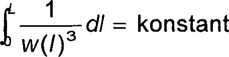
Die
Erfindung, wie sie in Anspruch 2 der vorliegenden Erfindung definiert
ist, schafft ein Gebläse,
das eine ringförmige
Wand umfasst, die so ausgebildet ist, dass sie von Flügelspitzen
eines Gebläses
bzw. Lüfters beabstandet
ist, wobei die ringförmige
Wand Schlitze aufweist, die an einem Abschnitt gegenüber den
Flügelspitzen
ausgebildet sind, um Verbindung zwischen dem Innenumfangsabschnitt
und dem Außenumfangsabschnitt
der ringförmigen
Wand herzustellen, so dass Luft durch die Schlitze in den Innenumfangsabschnitt
der ringförmigen
Wand gesaugt wird, wenn sich der Lüfter dreht,
dadurch gekennzeichnet,
dass
wenn die Länge
eines Luftstroms von dem Innenumfang der ringförmigen Wand zu dem Außenumfang
derselben als L angenommen wird, die Breite eines Spalts des Schlitzes
in einem Abstand l zu dem Innenumfang des Schlitzes als w(l) angenommen
wird und die Anzahl von Schlitzen in der Richtung einer Drehwelle
als n angenommen wird, um die Bedingung, die mit ausgedrückt wird, oder ihre angenäherte Bedingung
zu erfüllen,
die Anzahl der Schlitze verändert
wird und gleichzeitig die Breite w(l) des Spalts in Radial- und
in Umfangsrichtung desselben verändert
wird, so dass die Menge an Luft, die durch die Schlitze in den Innenumfangsabschnitt
der ringförmigen
Wand strömt, über den gesamten
Umfang im Wesentlichen gleich ist. Daher kann die P-Q-Kennlinie
des Gebläses
verbessert werden, und Geräuscharmut
kann erreicht werden.The invention as defined in claim 2 of the present invention provides a fan comprising an annular wall which is formed to be spaced from vane tips of a fan, the annular wall having slots which engage a portion opposite to the wing tips are formed to make connection between the inner peripheral portion and the outer peripheral portion of the annular wall, so that air is sucked through the slits in the inner peripheral portion of the annular wall when the fan rotates,
characterized in that
when the length of airflow from the inner circumference of the annular wall to the outer circumference thereof is taken as L, the width of a gap of the slot at a distance l to the inner circumference of the slot is taken as w (l) and the number of slots in the direction a rotation shaft is assumed to be n to satisfy the condition with 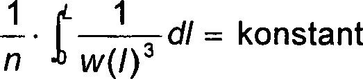
Bei
der Erfindung, wie sie in Anspruch 3 der vorliegenden Erfindung
definiert ist, ist der Winkel der Richtung eines Luftzustroms durch
den Schlitz so ausgebildet, dass er in Bezug auf eine Ebene senkrecht
zu der Gebläse-Drehwelle
geneigt ist. Daher kann der Wirkungsgrad des Gebläses verbessert
werden.at
of the invention as claimed in claim 3 of the present invention
is defined, the angle is the direction of an air flow through
the slot is formed so that it is perpendicular with respect to a plane
to the fan rotary shaft
is inclined. Therefore, the efficiency of the blower can be improved
become.
Bei
der Erfindung, wie sie in Anspruch 4 der vorliegenden Erfindung
definiert ist, nimmt die Breite des Spaltes des Schlitzes von dem
Innenumfang zu dem Außenumfang
in der gleichen Umfangsrichtung der ringförmigen Wand zu. Daher wird
der Strom von Luft durch den Schlitz gleichmäßig, und der Geräuschpegel
kann verringert werden.at
of the invention as claimed in claim 4 of the present invention
is defined, the width of the slot of the slot decreases from that
Inner circumference to the outer circumference
in the same circumferential direction of the annular wall. Therefore, will
the flow of air through the slot evenly, and the noise level
can be reduced.
Kurze Beschreibung
der ZeichnungenShort description
the drawings
1(a) ist eine Seitenansicht eines Gebläses gemäß Ausführung 1
der vorliegenden Erfindung, 1(b) ist
eine Vorderansicht desselben, 1(c) ist
eine Schnittansicht desselben und 1(d) ist
eine detaillierte Schnittansicht entlang der Linie X-X' in 1(b); 1 (a) Fig. 10 is a side view of a blower according to Embodiment 1 of the present invention; 1 (b) is a front view of the same, 1 (c) is a sectional view of the same and 1 (d) is a detailed sectional view along the line XX 'in 1 (b) ;
2(a) ist eine Seitenansicht eines Gebläses nach
dem Stand der Technik (japanische Patentanmeldungs-Offenlegungsschrift
Nr. 9-151450), 2(b) ist eine Vorderansicht
desselben, 2(c) ist eine Schnittansicht
desselben und 2(d) ist eine detaillierte
Schnittansicht entlang der Linie X-X' in 2(b); 2 (a) Fig. 10 is a side view of a prior art blower (Japanese Patent Application Laid-open No. 9-151450), 2 B) is a front view of the same, 2 (c) is a sectional view of the same and 2 (d) is a detailed sectional view along the line XX 'in 2 B) ;
3 ist
eine Ansicht, die den Strom von Luft an einem Schlitzabschnitt des
Gebläses
gemäß Ausführung 1
der vorliegenden Erfindung zeigt; 3 Fig. 12 is a view showing the flow of air at a slot portion of the blower according to Embodiment 1 of the present invention;
4 ist
eine Ansicht, die den Strom von Luft an einem Schlitzabschnitt des
Gebläses
nach dem Stand der Technik (japanische Patentanmeldungs-Offenlegungsschrift
Nr. 9-151450) zeigt; 4 Fig. 14 is a view showing the flow of air at a slot portion of the prior art blower (Japanese Patent Application Laid-Open Publication No. 9-151450);
5 ist
eine Ansicht, die den Strom von Luft im Inneren eines Schlitzes
des Gebläses
gemäß Ausführung 1
der vorliegenden Erfindung zeigt; 5 Fig. 11 is a view showing the flow of air inside a slot of the blower according to Embodiment 1 of the present invention;
6(a) ist ein P-Q-Kennliniendiagramm und 6(b) ist ein Diagramm einer Luftmengen-Geräuscheigenschaften-Kennlinie,
wobei darin die Kennlinien des Gebläses gemäß Ausführung 1 der vorliegenden Erfindung
mit denen eines herkömmlichen
Gebläses
verglichen werden; 6 (a) is a PQ characteristic diagram and 6 (b) FIG. 12 is a diagram of an air volume noise characteristic curve comparing the characteristics of the blower according to Embodiment 1 of the present invention with those of a conventional blower; FIG.
7(a) ist eine Seitenansicht und 7(b) ist eine Vorderansicht, die einen
Fall zeigen in dem die Außenform
eines Gehäuses
polygonal ist; 7 (a) is a side view and 7 (b) Fig. 10 is a front view showing a case where the outer shape of a housing is polygonal;
8(a) ist eine Seitenansicht und 8(b) ist eine Vorderansicht, die einen
Fall zeigen, in dem die äußere Form
eines Gehäuses
elliptisch ist; 8 (a) is a side view and 8 (b) Fig. 12 is a front view showing a case where the outer shape of a housing is elliptical;
9 ist
eine Ansicht, die die Form einer ringförmigen Platte eines anderen
Beispiels gemäß Ausführung 1
der vorliegenden Erfindung zeigt; 9 Fig. 12 is a view showing the shape of an annular plate of another example according to Embodiment 1 of the present invention;
10(a) ist eine Seitenansicht eines Gehäuses für ein Gebläse gemäß Ausführung 2
der vorliegenden Erfindung, 10(b) ist
eine Vorderansicht desselben, und 10(c) ist
eine detaillierte Schnittansicht entlang der Linie X-X' in 10(b); 10 (a) Fig. 10 is a side view of a blower housing according to Embodiment 2 of the present invention; 10 (b) is a front view of the same, and 10 (c) is a detailed sectional view along the line XX 'in 10 (b) ;
11(a) ist eine teilweise weggeschnittene
Perspektivansicht, und 11(b) ist eine
Draufsicht, die einen Aufbau einer Form zum Formen des Gehäuses für das Gebläse gemäß Ausführung 2
der vorliegenden Erfindung zeigen; 11 (a) is a partially cut away perspective view, and 11 (b) Fig. 10 is a plan view showing a structure of a mold for molding the housing for the blower according to Embodiment 2 of the present invention;
12 ist
eine Konstruktionsansicht der Form zum Formen des Gehäuses für das Gebläse gemäß Ausführung 2
der vorliegenden Erfindung; 12 Fig. 13 is a construction view of the mold for molding the housing for the blower according to Embodiment 2 of the present invention;
13 ist
eine Ansicht, die den Strom von Luft in der Nähe von Schlitzen des Gebläses gemäß Ausführung 2
der vorliegenden Erfindung zeigt; 13 Fig. 13 is a view showing the flow of air near slots of the blower according to Embodiment 2 of the present invention;
14(a) ist eine Seitenansicht eines Gehäuses für ein Gebläse gemäß Ausführung 3
der vorliegenden Erfindung, 14(b) ist
eine Vorderansicht desselben, 14(c) ist
eine detaillierte Schnittansicht entlang der Linie X-X' in 14(b),
und 14(d) ist eine detaillierte Schnittansicht
entlang der Linie Z-Z' in 14(b); 14 (a) Fig. 10 is a side view of a blower housing according to Embodiment 3 of the present invention; 14 (b) is a front view of the same, 14 (c) is a detailed sectional view along the line XX 'in 14 (b) , and 14 (d) is a detailed sectional view along the line ZZ 'in 14 (b) ;
15 ist
eine Schnittansicht eines herkömmlichen
Gebläses; 15 Fig. 10 is a sectional view of a conventional blower;
16(a) ist eine Vorderansicht des Gebläses nach
dem Stand der Technik (japanische Patentanmeldungs-Offenlegungs-Schrift
Nr. 9-151450), 16(b) ist eine Seitenansicht
desselben, und 16(c) ist eine Schnittansicht
desselben; 16 (a) Fig. 10 is a front view of the prior art blower (Japanese Patent Application Laid-open Publication No. 9-151450), 16 (b) is a side view of the same, and 16 (c) is a sectional view of the same;
17 ist
eine erläuternde
Ansicht, die einen Effekt eines Schlitzes des Gebläses zeigt;
und 17 Fig. 4 is an explanatory view showing an effect of a slit of the blower; and
18 ist
eine erläuternde
Ansicht, die einen Effekt eines Schlitzes des Gebläses zeigt. 18 Fig. 10 is an explanatory view showing an effect of a slit of the blower.
Beste Art und Weise der
Ausführung
der ErfindungBest way of
execution
the invention
(Ausführung 1)(Version 1)
1(a) bis 1(d) zeigen
ein Gebläse
gemäß Ausführung 1.
Ein Gehäuse 13 hat,
wie in 1(a) bis 1(d) dargestellt,
einen Sockelabschnitt 11, der als lagernder Trageabschnitt
dient, an dem ein Motorabschnitt befestigt ist, sowie einen Untersatzabschnitt 14,
der die Installationsebene des Gebläses ist, und enthält ringförmige Platten 7a bis 7e,
die über
Abstandshalter 8 an dem Untersatzabschnitt 14 in
Längsrichtung
verbunden sind. Diese ringförmigen
Platten 7a bis 7e haben eine Form, die erzeugt
wird, indem ein dünner
Ringkörper
so geschnitten wird, dass er an vier Seiten desselben geradlinig
ist. So werden laminierte ringförmige
Platten 7a bis 7e in der Richtung der Drehwelle
eines Axialgebläses
bzw. -Lüfters 1 installiert,
und alle diese Elemente werden mit einem Harz integral ausgebildet.
Des Weiteren ist ein Spalt jedes Schlitzes 6 so ausgebildet,
dass die Außenumfangsseite
einer ringförmigen
Wand größer ist
als die Innenumfangsseite desselben, indem der Querschnitt der ringförmigen Platte
in einer Spindelform ausgebildet wird. Des Weiteren wird die Breite
des Spalts jedes Schlitzes 6 in der Umfangsrichtung verändert, wodurch
der Zuströmwiderstand
jedes Abschnitts über
den gesamten Umfang gleich wird. 1 (a) to 1 (d) show a blower according to embodiment 1. A housing 13 has, as in 1 (a) to 1 (d) shown, a base portion 11 serving as a supporting support portion to which a motor portion is fixed, and a pedestal portion 14 , which is the installation level of the blower, and contains annular plates 7a to 7e that have spacers 8th at the pedestal section 14 are connected in the longitudinal direction. These annular plates 7a to 7e have a shape that is produced by cutting a thin ring body to be straight on four sides thereof. So are laminated annular plates 7a to 7e in the direction of the rotary shaft of an axial fan 1 installed, and all these elements are integrally formed with a resin. Furthermore, there is a gap of each slot 6 is formed so that the outer peripheral side of an annular wall is larger than the inner peripheral side thereof by forming the cross section of the annular plate in a spindle shape. Further, the width of the gap of each slot becomes 6 in the circumferential direction, whereby the inflow resistance of each section becomes the same over the entire circumference.
Um
die Merkmale des Gebläses
gemäß der vorliegenden
Erfindung zu verdeutlichen, wird das Gebläse dieser Ausführung erläutert, indem
es mit einem Gebläse
nach dem Stand der Technik verglichen wird. 2(a) bis 2(d) zeigen einen Fall, in dem die Breite
eines Spaltes eines Schlitzes in der radialen Richtung nicht verändert wird,
wie dies dem Stand der Technik nach (japanische Patentanmeldung
Nr. 9-151450) beschrieben ist.In order to clarify the characteristics of the blower according to the present invention, the blower of this embodiment will be explained by comparing it with a prior art blower. 2 (a) to 2 (d) show a case in which the width of a slit of a slit in the radial direction is not changed, as described in the prior art (Japanese Patent Application No. 9-151450).
Das
in 2 dargestellte Gebläse ist genau das gleiche wie
das Gebläse
dieser Ausführung,
die in 1 dargestellt ist, wobei jedoch die Breite w des
Spaltes des Schlitzes 6 in der radialen Richtung konstant ist. 4 ist
eine Ansicht, die den Strom von Luft in einem Querschnitt in der
Richtung X-X' in 2(b) zeigt, die das Gebläse nach
dem Stand der Technik zeigt. Ein Luftstrom 4, der von dem
Außenumfang
der ringförmigen
Wand in den Innenumfang derselben hineinströmt, strömt, wie in 4 dargestellt,
so in den Schlitz 6 hinein, dass er einmal mit dem Außenumfangsabschnitt
der ringförmigen
Wand kollidiert. Indem die Breite w eines Spaltes des Schlitzes 6 in
geeigneter Weise eingestellt wird, strömt der Luftstrom 5,
der durch den Schlitz 6 einströmt, durch den begradigenden
Effekt des Schlitzes 6 in einem laminaren Zustand in den
Innenumfang der ringförmigen
Wand hinein. Daher wird, obwohl ein zufriedenstellender Effekt hinsichtlich
der Wirkung der Verbesserung der P-Q-Kennlinie erzielt werden kann,
eine Turbulenz 21 des Luftstroms erzeugt, wenn der Luftstrom 5 mit
dem Außenumfangsabschnitt
der ringförmigen
Wand kollidiert, wodurch von diesem Abschnitt Geräusch erzeugt
wird. 3 zeigt den Strom von Luft in einem Querschnitt
in der Richtung X-X' in 1(b), die die vorliegende Erfindung zeigt.
Der Luftstrom 5, der über
den Außenumfang
der ringförmigen
Wand einströmt,
wird, wie in 3 dargestellt, entlang der spindelförmigen ringförmigen Platten 7a bis 7e in
den Innenumfang der ringförmigen
Wand hineingeleitet, so dass die Turbulenz von Luftstrom, die erzeugt
wird, wenn der Luftstrom 5 in den Schlitz 6 hineinströmt, auf
einem Minimum gehalten wird. Mit diesem Aufbau wird die P-Q-Kennlinie
verbessert, und gleichzeitig wird das an den Schlitzen 6 erzeugte
Geräusch
auf einem Minimum gehalten, so dass Verringerung des Gebläsegeräuschs erreicht
werden kann. Hier wird eine Bedingung zum Ausgleichen des Einström-Widerstandes
an den Schlitzen 6 beschrieben, indem ein Beispiel gewählt wird.This in 2 shown blower is exactly the same as the blower of this design, which in 1 is shown, but wherein the width w of the slot of the slot 6 is constant in the radial direction. 4 is a view showing the flow of air in a cross section in the direction XX 'in 2 B) shows, showing the blower according to the prior art. An airflow 4 flowing from the outer periphery of the annular wall into the inner periphery thereof, flows as in FIG 4 shown, so in the slot 6 in that it collides once with the outer peripheral portion of the annular wall. By the width w of a gap of the slot 6 is set appropriately, the air flow flows 5 passing through the slot 6 flows through, through the straightening effect of the slot 6 in a laminar state into the inner circumference of the annular wall. Therefore, although a satisfactory effect on the effect of improving the PQ characteristic can be obtained, turbulence is generated 21 the airflow generated when the airflow 5 collides with the outer peripheral portion of the annular wall, whereby noise is generated by this portion. 3 shows the flow of air in a cross section in the direction XX 'in FIG 1 (b) which shows the present invention. The airflow 5 , which flows in through the outer circumference of the annular wall is, as in 3 shown along the spindle-shaped annular plates 7a to 7e directed into the inner circumference of the annular wall, so that the turbulence of air flow, which is generated when the air flow 5 in the slot 6 flows in, is kept to a minimum. With this structure, the PQ characteristic is improved, and at the same time, that becomes the slits 6 noise kept to a minimum, so that reduction of the fan noise can be achieved. Here is a condition for equalizing the inflow resistance at the slots 6 described by an example is selected.
5 ist
eine schematische Ansicht, die eine Geschwindigkeitsverteilung von
Luft in dem Schlitz 6 zeigt. Der Strom von Luft in dem
Schlitz 6 wird als ein Laminarstrom angenommen, und die
Trägheitskraft
von Luft, die Kompression von Luft usw. werden vernachlässigt. In 5 kennzeichnet
L die Länge
in der Richtung eines Luftstroms von dem Innenumfang zu dem Außenumfang
der ringförmigen
Wand, w(l) kennzeichnet die Breite des Spaltes des Schlitzes an
einer Position in einem Abstand l zu dem Innenumfang des Schlitzes,
p(l) kennzeichnet einen Druck an dieser Position, u kennzeichnet
die Geschwindigkeit des Luftstroms und Q kennzeichnet die Menge
an Luft, die pro Zeiteinheit über
eine Schlitzeinheit einströmt.
Die Verteilung der Geschwindigkeit u in dem Schlitz 6 ist,
wie in 5 dargestellt, parabolisch, und die Menge Q an
Luft, die pro Zeiteinheit durch eine Schlitzeinheit einströmt, wird
ausgedrückt
mit: wobei
n die Viskosität
von Luft ist. Dabei wird, wenn die Länge in der Strömungsrichtung
des Schlitzes 6 mit L angenommen wird und die Differenz
des atmosphärischen
Drucks zwischen der Innenseite und der Außenseite des Schlitzes mit ΔP angenommen
wird, Gleichung 1 wie folgt umgestellt: 5 is a schematic view showing a velocity distribution of air in the slot 6 shows. The flow of air in the slot 6 is assumed to be a laminar flow, and the inertial force of air, the compression of air, etc. are neglected. In 5 L indicates the length in the direction of an air flow from the inner circumference to the outer circumference of the annular wall, w (l) indicates the width of the gap of the slot at a position at a distance l to the inner circumference of the slot, p (l) indicates a pressure at this position, u indicates the velocity of the air flow and Q indicates the amount of air flowing in through a slot unit per unit time. The distribution of the speed u in the slot 6 is how in 5 represented, parabolic, and the amount Q of air, which flows through a slot unit per unit time, is expressed with: where n is the viscosity of air. This is when the length in the flow direction of the slot 6 is assumed to be L and the difference of the atmospheric pressure between the inside and the outside of the slot is assumed to be ΔP, equation 1 is changed as follows:
Da ΔP durch die
Drehung eines Lüfters
verursacht wird und die Viskosität
n von Luft an jedem Abschnitt konstant ist, wird die Bedingung,
unter der Q konstant wird, wie folgt ausgedrückt:Since ΔP by the
Rotation of a fan
is caused and the viscosity
n of air at each section is constant, the condition
under which Q becomes constant is expressed as follows:
So
ergibt sich, dass, indem die Breite des Spaltes des Schlitzes 6 gemäß dieser
Gleichung optimiert wird, die Einströmmenge an Luft über den
gesamten Umfang gleich wird, wodurch Flügelschwingungen und dergleichen
eingeschränkt
werden, so dass die Verschlechterung der P-Q-Kennlinie und die Zunahme
von Geräuschentwicklung
verhindert werden können.So it follows that, adding the width of the slot of the slot 6 is optimized according to this equation, the inflow amount of air over the entire circumference becomes the same, whereby wing vibrations and the like are restricted, so that the deterioration of the PQ characteristic and the increase of noise can be prevented.
Die
oben beschriebene Optimierungsbedingung ist eine Bedingung in dem
Zustand, in dem die Trägheitskraft
von Luft, die Kompression von Luft und dergleichen vernachlässigt werden,
so dass die tatsächliche Optimierungsbedingung
geringfügig
von dieser Bedingung abweicht. Diese Abweichung ist jedoch sehr
gering, da ein Zustand herrscht, in dem der Strom in dem Schlitzabschnitt
laminar ist, d.h. ein Zustand, in dem die Träg heitskraft von Luft so eingestellt
ist, dass sie relativ zu der Viskositätskraft gering ist. Eine weitere
optimale Form kann bestimmt werden, indem ein Experiment, eine Fluidanalyse
oder dergleichen unter Verwendung eines Computers auf der Basis
einer Form durchgeführt
wird, die anhand der oben beschriebenen Optimierungsbedingungen
bestimmt wird, und indem eine gewisse Korrektur hinzugefügt wird.The
The optimization condition described above is a condition in which
State in which the inertial force
of air, the compression of air and the like are neglected,
so that the actual optimization condition
slight
deviates from this condition. However, this deviation is very
low, since there is a state in which the current in the slot portion
is laminar, i. a condition in which the inertia of air is so adjusted
is that it is low relative to the viscosity power. Another
optimal shape can be determined by an experiment, a fluid analysis
or the like using a computer on the base
a form performed
will be based on the optimization conditions described above
is determined and by adding some correction.
Als
Nächstes
werden die Messergebnisse der tatsächlichen Eigenschaften des
Gebläses,
das auf Basis der oben beschriebenen Bedingung optimiert worden
ist, dargestellt. 6(a) und 6(b) zeigen die Ergebnisse eines experimentellen
Vergleichs der Eigenschaften des herkömmlichen Gebläses ohne
Schlitz in der ringförmigen
Wand des Gebläses,
bei dem die Breite des Spaltes des Schlitzes über den gesamten Umfang konstant
ist, des Gebläses,
bei dem die Breite w des Spaltes des Schlitzes nur in der Umfangsrichtung
verändert
wird, wie dies im Stand der Technik (japanische Patentanmeldung
Nr. 9-151450) beschrieben ist, und des Gebläses gemäß der vorliegenden Ausführung, bei
dem die Breite des Spaltes des Schlitzes sowohl in Umfangs- als
auch in radialer Richtung verändert
wird. Für
diese Gebläse
wurden Gebläseteile,
die derzeit in Massenherstellung gefertigt werden, verwendet, und
nur das Gehäuse
wurde hergestellt, indem es versuchsweise geschnitten wurde. Die
Messung wurde an jedem Gebläse
unter den gleichen Bedingungen durchgeführt. Alle verwendeten Gebläse hatten
die gleiche Größe, Lüfter dieser
Gebläse
hatten die gleiche Größe und Form
und Motoren, die zum Antreiben dieser Lüfter verwendet wurden, hatten
die gleichen Eigenschaften. 6(a) ist ein
Diagramm, in dem die P-Q-Kennlinien verglichen werden, wenn die
Lüfter
dieser Gebläse
mit dergleichen Drehgeschwindigkeit angetrieben werden. Bei dem
herkömmlichen
Gebläse
ohne Schlitze in der ringförmigen Wand
nimmt die Luftmenge extrem ab und geht in einen Abreißzustand über, wenn
ein gewisser Grad an statischem Druck wirkt. In dem Fall, in dem
die Breite eines Spaltes des Schlitzes konstant ist, verbessert
sich der Abreißzustand
verglichen mit dem herkömmlichen
Gebläse,
der Abreißzustand
wird jedoch nicht vollständig beseitigt.
Im Unterschied dazu wird, wenn die Breite eines Spaltes des Schlitzes
nur in der Umfangsrichtung verändert
wird, und wenn sie sowohl in der Umfangsrichtung als auch in der
radialen Richtung verändert
wird, der Abreißzustand
im Wesentlichen vollständig
vermieden. 6(b) ist ein Diagramm,
in dem die Eigenschaften bezüglich
des Verhältnisses
von Luftmenge und Geräuschentwicklung
verglichen werden, wenn die Lüfter dieser
Gebläse
mit der gleichen Drehgeschwindigkeit angetrieben werden. Das herkömmliche
Gebläse
ohne Schlitze in der ringförmigen
Wand hat einen Bereich, in dem das Geräusch beim Strömungsabriss
des Lüfters zu nimmt,
die anderen drei Typen von Gebläsemittelschlitzen
haben jedoch keinen Bereich, in dem sich das Geräusch stark verändert, sondern
weisen stabile Eigenschaften über
den gesamten Bereich auf. In dem Fall jedoch, in dem die Schlitzbreite
konstant ist, oder wenn die Schlitzbreite nur in der Umfangsrichtung
verändert wird,
ist das Geräusch
insgesamt verglichen mit dem Fall hoch, in dem die Schlitzbreite
sowohl in der Umfangsrichtung als auch der radialen Richtung verändert wird,
und das Geräusch
ist in dem Bereich etwas höher als
das des herkömmlichen
Gebläses,
in dem der statische Druck niedrig ist. Wenn die Schlitzbreite sowohl
in der Umfangsrichtung als auch der radialen Richtung verändert wird,
weist das Geräusch über den
gesamten Bereich einen niedrigen Wert auf und ist in nahezu allen
Bereichen niedriger als das des herkömmlichen Gebläses. Obwohl
die oben beschriebenen Kennlinien diejenigen für den Fall sind, dass der Lüfter mit
der gleichen Drehgeschwindigkeit angetrieben wird, wird das Gebläse im tatsächlichen
Gebrauch häufig
in einem Zustand des gleichmäßigen Blasens
von Luft eingesetzt, d.h. in einem Zustand, in dem der statische
Druck und die Luftmenge im Gleichgewicht sind. In einem solchen
Luftblaszustand kann das Gebläse
der vorliegenden Erfindung bei niedriger Drehgeschwindigkeit des
Lüfters
betrieben werden, so dass der Geräuschunterschied zwischen dem
Gebläse
der vorliegenden Erfindung und dem herkömmlichen Gebläse ohne
Schlitze in der ringförmigen
Wand weiter zunimmt, und gleichzeitig wird der Energieverbrauch
an dem Motorabschnitt verringert, so dass ein Gebläse mit niedrigem
Geräusch
und niedrigem Energieverbrauch geschaffen wird.Next, the measurement results of the actual characteristics of the blower optimized on the basis of the condition described above are shown. 6 (a) and 6 (b) show the results of an experimental comparison of the characteristics of the conventional fan without slot in the annular wall of the blower in which the width of the slit of the slit is constant over the entire circumference of the blower, in which the width w of the slit of the slit is changed only in the circumferential direction, as in the prior art (Japanese Patent Application no. 9-151450), and the blower according to the present embodiment, wherein the width of the slit of the slit is changed in both the circumferential and radial directions. For these blowers, blower parts that are currently mass-produced were used, and only the housing was made by trialing it. The measurement was performed on each blower under the same conditions. All blowers used were the same size, fans of these blowers had the same size and shape and motors that were used to drive these fans had the same characteristics. 6 (a) FIG. 12 is a graph comparing the PQ characteristics when the fans of these fans are driven at the same rotational speed. In the conventional fan with no slits in the annular wall, the amount of air decreases extremely and becomes a tearing condition when a certain degree of static pressure is applied. In the case where the width of a slit of the slit is constant, the breakaway state improves as compared with the conventional blower, but the breakaway state is not completely eliminated. In contrast, when the width of a slit of the slit is changed only in the circumferential direction, and when it is changed in both the circumferential direction and the radial direction, the tear-off state is substantially completely avoided. 6 (b) FIG. 13 is a graph comparing the air volume / noise ratio characteristics when the fans of these fans are driven at the same rotational speed. The conventional fan with no slits in the annular wall has an area in which the noise at the stall of the fan increases, but the other three types of fan slits have no area where the noise changes greatly, but have stable characteristics throughout Range up. However, in the case where the slit width is constant, or when the slit width is changed only in the circumferential direction, the total noise is high as compared with the case where the slit width is changed in both the circumferential direction and the radial direction, and the noise is slightly higher in the range than that of the conventional blower in which the static pressure is low. When the slit width is changed in both the circumferential direction and the radial direction, the noise has a low value over the entire area and is lower than that of the conventional blower in almost all areas. Although the characteristics described above are those for the case where the fan is driven at the same rotational speed, in actual use, the fan is often used in a state of uniform blowing of air, that is, in a state where the static pressure and the Air quantity are in equilibrium. In such an air-blowing state, the blower of the present invention can be operated at a low rotational speed of the fan, so that the noise difference between the blower of the present invention and the conventional blower without slits in the annular wall further increases, and at the same time the power consumption at the motor portion is reduced so that a fan with low noise and low energy consumption is created.
In
der oben stehenden Beschreibung ist die Außenumfangsform der ringförmigen Wand 2 eine
Kreisform, deren vier Seiten in einer planen Form abgeschnitten
sind. Es erübrigt
sich jedoch zu erwähnen,
dass für
jede beliebige Außenumfangsform,
wie beispielsweise eine polygonale Form, wie sie in 7 dargestellt ist,
und eine elliptische Form, wie sie in 8 dargestellt
ist, Optimierung unter der gleichen Bedingung durchgeführt werden
kann, so dass ein Gebläse
mit hoher P-Q-Kennlinie und geringer Geräuschentwicklung geschaffen
werden kann. Des Weiteren wird, obwohl dies in der Figur nicht dargestellt
ist, wenn die Außenumfangsform
der ringförmigen
Wand kreisförmig
ist, die Breite des Spaltes des Schlitzes nur in der radialen Richtung
verändert,
so dass der Zustrom von Luft zu dem Schlitz gleichmäßig ist,
wodurch der gleiche Effekt erzielt werden kann. Des Weiteren kann
die ringförmige
Platte 7a bis 7e, obwohl der Querschnitt in der
oben beschriebenen Ausführung
eine Spindelform hat, sie, wie in 9(a) dargestellt
ist, eine trapezartige Form haben oder, wie in 9(b) dargestellt,
eine dreieckige Form. Unter dem Aspekt des gleichmäßigen Zustroms
des Luftstroms 5 ist die Spindelform, wie sie in der oben
beschriebenen Ausführung
dargestellt ist, anderen Formen überlegen.
Selbst wenn die Form trapezartig oder dreieckig ist, wird jedoch
die Geräuschentwicklung
verglichen mit dem Fall nach dem Stand der Technik verringert, bei
dem die Breite w des Spaltes des Schlitzes in der radialen Richtung
nicht verändert
wird. Des Weiteren sind die trapezartige Form und die dreieckige
Form einfacher als die Spindelform, so dass die ringförmige Platte
mit diesen Formen leicht in Massenfertigung hergestellt werden kann
und die Produktivität
hoch ist. Als Alternative dazu wird, wenn der Querschnitt der ringförmigen Platte 7a bis 7e in
einer Tragflügelform
ausgebildet wird, so dass die Breite des Spaltes des Schlitzes in
dem Mittelabschnitt minimal ist, wie dies in 9(c) dargestellt
ist, die Form kompliziert, so dass es schwierig ist, die ringförmigen Platten 7a bis 7e und
das Gehäuse 13 integral
mit einem Verfahren, wie beispielsweise Harz-Spritzgießen, zu
formen, wodurch die ringförmigen
Platten für
die Massenproduktion ungeeignet werden. Bei der Tragflügelform
jedoch strömt
Luft zusammen mit einem gleichmäßigen Einströmen von
Luft an dem Außenumfangsabschnitt
der ringförmigen
Wand in einen breiten Bereich des Lüfters 1 selbst an
dem Innenumfangsabschnitt der ringförmigen Wand ein, so dass der
Zustand von Luftströmen
an dem Lüfter 1 gleichmäßig wird.
So wird das Abreißen
von Luftströmen
an dem Lüfter 1 eingeschränkt, und
die Eigenschaften werden weiter verbessert.In the above description, the outer peripheral shape of the annular wall 2 a circular shape whose four sides are cut off in a plane shape. It is needless to say, however, that for any external peripheral shape, such as a polygonal shape, as shown in FIG 7 is shown, and an elliptical shape, as in 8th can be performed optimization under the same condition, so that a blower with high PQ characteristic and low noise can be created. Further, although not shown in the figure, when the outer peripheral shape of the annular wall is circular, the width of the slit of the slit is changed only in the radial direction, so that the influx of air to the slit is uniform, whereby the same Effect can be achieved. Furthermore, the annular plate 7a to 7e Although the cross section in the above-described embodiment has a spindle shape, as shown in FIG 9 (a) is shown to have a trapezoidal shape or, as in 9 (b) represented, a triangular shape. In the aspect of the steady influx of airflow 5 is the spindle shape, as shown in the embodiment described above, superior to other forms. However, even if the shape is trapezoidal or triangular, the noise is reduced as compared with the case of the prior art in which the width w of the slit of the slit is not changed in the radial direction. Furthermore, the trapezoidal shape and the triangular shape are simpler than the spindle shape, so that the annular plate having these shapes can be easily mass-produced and the productivity is high. Alternatively, when the cross section of the annular plate 7a to 7e is formed in a hydrofoil shape, so that the width of the gap of the slot in the central portion is minimal, as in 9 (c) is shown, the shape is complicated, so that it is difficult, the annular plates 7a to 7e and the case 13 integral with a method such as resin injection molding, whereby the annular plates become unsuitable for mass production. However, in the airfoil shape, air, together with a smooth inflow of air at the outer peripheral portion of the annular wall, flows in a wide area of the fan 1 even on the inside Peripheral portion of the annular wall, so that the state of air flows to the fan 1 becomes even. This is how the tearing off of air flows on the fan 1 restricted, and the properties are further improved.
(Ausführung 2)(Version 2)
10 zeigt
Ausführung 2.
In der oben beschriebenen Ausführung
1 sind ein Formverfahren und dergleichen für ein Gehäuse nicht speziell beschrieben
worden. Bei der vorliegenden Ausführung werden ein Formverfahren
für ein
Gehäuse
und ein Beispiel für
Optimierungsanpassung an das Formverfahren beschrieben. 10(a) bis 10(c) zeigen
ein Gehäuse
für ein
Gebläse
der vorliegenden Ausführung.
In 10(a) bis 10(c) hat
ein Gehäuse 13 einen
Sockelabschnitt 11, der als ein lagernder Trageabschnitt
dient, an dem ein Motorabschnitt befestigt ist, sowie einen Untersatzabschnitt 14,
der eine Installationsebene des Gebläses ist, und enthält ringförmige Platten 7a bis 7e,
die in Längsrichtung über Abstandshalter 8 an
dem Untersatzabschnitt 14 zu verbinden sind. Diese ringförmigen Platten 7a bis 7e haben
eine Form, die erzeugt wird, indem ein dünner Ringkörper so geschnitten wird, dass
er an vier Seiten desselben geradlinig ist. Alle diese Elemente
werden integral durch Harz-Spritzgießen geformt. Ein Spalt jedes
Schlitzes 6a bis 6d ist so geformt, dass die Außenumfangsseite
einer ringförmigen
Wand 2 größer ist
als die Innenumfangsseite derselben, indem der Querschnitt der ringförmigen Platte 7a bis 7e in
einer Spindelform ausgebildet wird, und des Weiteren wird eine Breite
w eines Spalts jedes Schlitzes 6a bis 6e in der
Umfangsrichtung verändert,
wodurch der Zuströmwiderstand jedes
Abschnitts über
den gesamten Umfang wie bei Ausführung
1 gleich wird. Diese Ausführung
unterscheidet sich von der Ausführung
1 jedoch dahingehend, dass die Schlitze 6a bis 6e so
ausgebildet sind, dass sie in Bezug auf eine Ebene senkrecht zu
der Drehwelle eines Lüfters 1 leicht
geneigt sind, und diese Neigung wird in Abhängigkeit von dem Schlitz verändert. 10 shows execution 2 , In Embodiment 1 described above, a molding method and the like for a housing have not been specifically described. In the present embodiment, a molding method for a housing and an example of optimization adaptation to the molding method will be described. 10 (a) to 10 (c) show a housing for a blower of the present embodiment. In 10 (a) to 10 (c) has a housing 13 a base section 11 serving as a supporting support portion to which a motor portion is fixed, and a pedestal portion 14 , which is an installation plane of the blower, and contains annular plates 7a to 7e , which are longitudinally over spacers 8th at the pedestal section 14 to connect. These annular plates 7a to 7e have a shape that is produced by cutting a thin ring body to be straight on four sides thereof. All of these elements are molded integrally by resin injection molding. A gap of each slot 6a to 6d is shaped so that the outer peripheral side of an annular wall 2 is larger than the inner peripheral side thereof by the cross section of the annular plate 7a to 7e is formed in a spindle shape, and further, a width w of a gap of each slot 6a to 6e in the circumferential direction, whereby the inflow resistance of each section becomes the same over the entire circumference as in Embodiment 1. *** " However, this embodiment differs from the embodiment 1 in that the slots 6a to 6e are formed so that they are relative to a plane perpendicular to the rotary shaft of a fan 1 are slightly inclined, and this inclination is changed depending on the slot.
11 ist
eine schematische Ansicht, die einen Aufbau einer Form zum Formen
des Gehäuses 13 der vorliegenden
Ausführung
zeigt. Die Form hat, wie in 11 dargestellt,
einen relativ einfachen Aufbau, der aus einer oberen und einer unteren
Form 15 und 16 sowie zwei Gleitkernen 17 und 18 besteht.
Ein derartiger Formaufbau ist als Verfahren zum Formen eines Gehäuses für ein herkömmliches
Gebläse
ohne Schlitze in der ringförmigen
Wand sehr verbreitet und eignet sich hervorragend für die Massenproduktion.
Um das Gehäuse
mit diesem Formaufbau zu formen, werden, wie in 10(b) dargestellt,
Abstandshalter 8a an den vier Eckenabschnitten in der radialen
Richtung ausgebildet, jedoch werden Abstandshalter 8b an
vier Seitenabschnitten so ausgebildet, dass sie in Bezug auf die
radiale Richtung geneigt sind. Wenn die Abstandshalter 8b auf
diese Weise geneigt sind, wird, obwohl die Abstandshalter 8b den
Luftstrom von dem Außenumfang
der ringförmigen Wand 2 zu
dem Innenumfang derselben behindern und die Eigenschaften verschlechtern,
der Effekt der Neigung der Abstandshalter 8b verringert,
indem die Abstandshalter 8b an den Mittelpunkten der vier
Seitenabschnitte angeordnet werden, an denen die Länge L in
der radialen Richtung der ringförmigen
Wand am geringsten ist. Des Weiteren gleiten die Gleitkerne 17 und 18 so,
dass sie einander gegenüberliegen,
weil sie eine plane Form senkrecht zu der Mittelachse des Gehäuses beibehalten.
Indem die Tatsache genutzt wird, dass die Schlitze 6a bis 6d des
Gehäuses 13 in
Richtung der Außenumfangsseite
breiter werden, werden die Winkel der oberen Fläche 19 und der unteren
Fläche 20 des
Schlitzes 6a wie in 12 dargestellt
verändert,
so dass die Schlitze 6a und 6d, die in Bezug auf
diese Flächen
geneigt sind, geformt werden können. 11 is a schematic view showing a structure of a mold for molding the housing 13 the present embodiment shows. The shape has, as in 11 shown, a relatively simple structure consisting of an upper and a lower mold 15 and 16 as well as two sliding cores 17 and 18 consists. Such a mold construction is widely used as a method for molding a housing for a conventional fan without slits in the annular wall and is excellent for mass production. To form the housing with this mold construction, as in 10 (b) shown, spacers 8a are formed at the four corner portions in the radial direction, however, spacers 8b formed on four side portions so as to be inclined with respect to the radial direction. If the spacers 8b are inclined in this way, although the spacers 8b the flow of air from the outer periphery of the annular wall 2 to hinder the inner periphery thereof and deteriorate the properties, the effect of the inclination of the spacers 8b decreased by the spacers 8b be arranged at the midpoints of the four side portions at which the length L in the radial direction of the annular wall is lowest. Furthermore, the sliding cores slide 17 and 18 so that they face each other because they maintain a planar shape perpendicular to the central axis of the housing. By taking advantage of the fact that the slots 6a to 6d of the housing 13 become wider in the direction of the outer peripheral side, the angles of the upper surface 19 and the lower surface 20 of the slot 6a as in 12 shown changed so that the slots 6a and 6d , which are inclined with respect to these surfaces, can be shaped.
Dieser
Aufbau, bei dem die Schlitze 6a bis 6d in Bezug
auf die Ebene senkrecht zu der Drehwelle eines Lüfters leicht geneigt sind,
hat die im Folgenden beschriebenen Auswirkungen. 13(a) und 13(b) zeigen einen Luftstrom 5 an
dem Schlitzabschnitt. Ein Luftstrom 5a, der durch die Schlitze 6a bis 6d in
einem normalen Luftblaszustand einströmt, wird, wie in 13(a) dargestellt, durch den Lüfter 1 in
einen Luftstrom 5b im Wesentlichen in axialer Richtung
umgewandelt. Dabei wird eine gewisse Energiemenge benötigt, um
die Richtung des Luftstroms 5 zu ändern. Daher ist ein Zustand,
in dem die Innenumfangsseite der Schlitze 6a bis 6d in
der Austrittsrichtung des Luftstroms geneigt ist, um die Änderung
des Winkels auf ein Minimum zu verringern, bezüglich des Wirkungsgrades ausgezeichnet.
Des Weiteren wird, indem die Schlitze 6a bis 6d geneigt
werden, die Länge
L' in der Strömungsrichtung
des Luftstroms 5 größer als
die Länge
L zwischen dem Innenumfang und dem Außenumfang der ringförmigen Wand 2.
Daher ist, wenn die Breite w des Spaltes des Schlitzes 6a bis 6d gleich
eingestellt ist, ein Effekt, durch den der Luftstrom 5 zu
einem laminaren Strom wird, stärker
als in dem Fall, in dem die Schlitze 6a bis 6d nicht
geneigt sind. Des Weiteren ist bei dieser Ausführung bei den Schlitzen 6a und 6d der
stromauf liegenden Seite die Innenumfangsseite in der Austrittsrichtung
des Luftstroms, wie oben beschrieben, geneigt, bei dem Schlitz 6d an
der stromab liegenden Seite jedoch ist die Außenumfangsseite umgekehrt in
der Austrittsrichtung des Luftstroms geneigt. Dies hat den Zweck,
die Luft in einem breiten Bereich in den Innenumfang der ringförmigen Wand 2 einzuleiten
und so die Luftmenge zu vergrößern, indem
die Winkel der Schlitze 6a bis 6d verändert werden.
Des Weiteren tritt, wie in 13(b) dargestellt,
wenn das Gebläse
in einem Zustand von hohem statischen Druck eingesetzt wird, Scheibenzirkulation 12 auf,
so dass Luft durch den Schlitz 6d an der stromab liegenden
Seite rückwärts strömt und wieder
in die Schlitze 6a bis 6c an der stromauf liegenden
Seite eingesaugt wird, wodurch der Wirkungsgrad verringert wird. Die
Außenumfangsseite
des Schlitzes 6d an der stromab liegenden Seite ist jedoch
in der Austrittsrichtung des Luftstroms 5 entgegengesetzt
zu den Schlitzen 6a, 6b und 6c an der
stromauf liegenden Seite geneigt, so dass der Strömungsweg
von dem Schlitz 6d an der stromab liegenden Seite zu den
Schlitzen 6a, 6b und 6c an der stromauf
liegenden Seite verlängert
wird, was den Effekt der Einschränkung
der Scheibenzirkulation 12 hat.This construction in which the slots 6a to 6d Slightly inclined with respect to the plane perpendicular to the rotating shaft of a fan has the effects described below. 13 (a) and 13 (b) show a flow of air 5 at the slot portion. An airflow 5a passing through the slots 6a to 6d flows in a normal air-blowing state, as in 13 (a) represented by the fan 1 in a stream of air 5b essentially converted in the axial direction. This requires a certain amount of energy to control the direction of the airflow 5 to change. Therefore, a condition in which the inner peripheral side of the slots 6a to 6d is inclined in the discharge direction of the air flow to reduce the change of the angle to a minimum, excellent in the efficiency. Furthermore, by making the slots 6a to 6d be inclined, the length L 'in the flow direction of the air flow 5 larger than the length L between the inner circumference and the outer circumference of the annular wall 2 , Therefore, if the width w of the slit of the slot 6a to 6d is set equal, an effect by which the air flow 5 becomes a laminar flow stronger than in the case where the slits 6a to 6d are not inclined. Furthermore, in this embodiment, the slots 6a and 6d the upstream side, the inner peripheral side in the discharge direction of the air flow, as described above, inclined at the slot 6d however, on the downstream side, the outer peripheral side is inclined in the reverse direction of the air flow. This has the purpose of air in a wide range in the inner circumference of the annular wall 2 to initiate and thus increase the amount of air by adjusting the angles of the slots 6a to 6d to be changed. Furthermore, as in 13 (b) shown when the blower is inserted in a state of high static pressure, disc circulation 12 on, allowing air through the slot 6d flows backwards on the downstream side and back into the slots 6a to 6c is sucked in on the upstream side, whereby the efficiency is reduced. The outer peripheral side of the slot 6d on the downstream side, however, is in the exit direction of the air flow 5 opposite to the slots 6a . 6b and 6c inclined at the upstream side, so that the flow path from the slot 6d on the downstream side to the slots 6a . 6b and 6c extended on the upstream side, causing the effect of restricting the disc circulation 12 Has.
Mit
dem oben beschriebenen Aufbau kann ein Gebläse, das sich sehr gut für Massenproduktion
eignet, ausgezeichnete P-Q-Kennlinie, geringe Geräuschentwicklung
und hohen Wirkungsgrad aufweist, geschaffen werden, indem lediglich
eine geringfügige
Korrektur an dem herkömmlichen
Herstellungsverfahren und den Einrichtungen für ein Gebläse vorgenommen wird, auch wenn
die Form ein wenig kompliziert wird.With
The construction described above can be a fan that works very well for mass production
suitable, excellent P-Q characteristic, low noise
and high efficiency can be created by merely
a minor one
Correction to the conventional one
Manufacturing process and facilities for a blower is made, even if
the shape gets a little complicated.
(Ausführung 3)(Version 3)
Obwohl
die Anzahl von Schlitzen 6 bei den oben beschriebenen Ausführungen über den
gesamten Umfang konstant ist, kann die gleiche Optimierung durchgeführt werden,
indem zusätzlich
die Anzahl von Schlitzen 6 geändert wird. 14(a) bis 14(c) zeigen ein Gebläsegehäuse von Ausführung 3.
In 14(a) unterscheidet sich die Anzahl
von Schlitzen 6 an vier Seitenabschnitten von der Anzahl
an anderen Abschnitten bei dieser Ausführung. Wenn sich die Anzahl
von Schlitzen auf diese Weise ändert,
ist es nicht der Zuströmwiderstand
lediglich eines Schlitzes, sondern die Menge an Luft, die durch
eine Vielzahl von Schlitzen einströmt, die über den gesamten Umfang gleich
werden sollte. Die Menge an Luft pro einem Schlitz wird auf die gleiche
Weise wie bei der zweiten Gleichung in Ausführung 1 ausgedrückt. Daher
wird, indem die Anzahl von Schlitzen an einem betreffenden Abschnitt
mit n angenommen wird, die Summe ΣQ
der Menge an Luft, die über
diesen Abschnitt einströmt,
ausgedrückt
mit: wobei ΔP eine Druckdifferenz
ist, die durch die Drehung des Lüfters
verursacht wird, und η die
Viskosität
von Luft ist, die an jedem Abschnitt konstant ist. Daher wird die
Bedingung, unter der ΣQ
konstant ist, wie folgt ausgedrückt:Although the number of slots 6 In the embodiments described above, it is constant over the entire circumference, the same optimization can be performed by additionally increasing the number of slots 6 will be changed. 14 (a) to 14 (c) show a blower housing of execution 3. In 14 (a) the number of slots is different 6 on four side sections from the number of other sections in this embodiment. When the number of slots changes in this way, it is not the inflow resistance of only one slot but the amount of air flowing in through a plurality of slots that should become equal over the entire circumference. The amount of air per one slot is expressed in the same manner as in the second equation in Embodiment 1. Therefore, by assuming the number of slots at a respective section as n, the sum ΣQ of the amount of air flowing in through this section is expressed as: where ΔP is a pressure difference caused by the rotation of the fan, and η is the viscosity of air that is constant at each section. Therefore, the condition under which ΣQ is constant is expressed as follows:
Wenn
daraufhin die Breite des Spaltes des Schlitzes 6 und die
Anzahl von Schlitzen 6 entsprechend dieser Gleichung verändert wird,
wird die Einströmmenge
an Luft über
den gesamten Umfang gleich, so dass ein Gebläse mit großer Luftmenge und geringer
Geräuschentwicklung
geschaffen wird, bei dem Flügelschwingungen,
Scheibenzirkulation und dergleichen eingeschränkt werden, die P-Q-Kennlinie
nicht verschlechtert wird und die Geräuschentwicklung nicht zunimmt.If thereupon the width of the slit of the slit 6 and the number of slots 6 is changed according to this equation, the inflow amount of air over the entire circumference becomes the same, so that a blower with a large amount of air and low noise is provided, in which wing vibration, disc circulation and the like are restricted, the PQ characteristic is not deteriorated and the noise generation does not increase.
Wie
aus der Beschreibung der oben stehenden Ausführungen gemäß der Erfindung, wie sie in
Anspruch 1 und 2 definiert ist, ersichtlich wird, ist die ringförmige Wand
so ausgebildet, dass sie von den Flügelspitzen des Lüfters beabstandet
ist, ist die ringförmige
Wand mit Schlitzen versehen, die Verbindung zwischen dem Innenumfangsabschnitt
und dem Außenumfangsabschnitt
der ringförmigen
Wand an dem den Flügelspitzen
gegenüber
liegenden Abschnitt herstellen, und die Breite des Spaltes des Schlitzes
wird so verändert, dass
die Menge an Luft, durch die Schlitze in den Innenumfangsabschnitt
der ringförmigen
Wand strömt, über den
gesamten Umfang gleich ist. Daher wird der Luftblaszustand verbessert,
indem das Auftreten von Wirbeln und das Abreißen von Luftströmen an der
Ansaugseite des Lüfters
eingeschränkt
werden. Gleichzeitig können Flügelschwingungen,
Scheibenzirkulation und dergleichen eingeschränkt werden. Darüber hinaus
kann die P-Q-Kennlinie verglichen mit dem herkömmlichen Gebläse verbessert
werden und eine Verringerung der Geräuschentwicklung kann erreicht
werden.As
from the description of the above embodiments according to the invention, as in
Claim 1 and 2 is defined, is the annular wall
designed so that it is spaced from the wing tips of the fan
is, is the annular
Wall provided with slots, the connection between the inner peripheral portion
and the outer peripheral portion
the annular
Wall at the wing tips
across from
Make the lying section, and the width of the gap of the slot
is changed so that
the amount of air through the slots in the inner peripheral portion
the annular
Wall is streaming over
entire circumference is the same. Therefore, the air blowing state is improved,
by the occurrence of vortices and the tearing of air currents at the
Suction side of the fan
limited
become. At the same time, wing vibrations,
Disc circulation and the like are restricted. Furthermore
can improve the P-Q characteristic as compared with the conventional blower
and a reduction in noise can be achieved
become.

