Die Erfindung betrifft eine Vorrichtung
zur individuellen Steuerung der Blätter eines Rotors mit wenigstens
vier Blättern
für einen
Luftfahrzeug-Drehflügel,
insbesondere einen Hubschrauber-Hauptrotor.The invention relates to a device
for individual control of the blades of a rotor with at least
four sheets
for one
Aircraft rotating aerofoil,
especially a helicopter main rotor.
Obwohl die Vorrichtung zur individuellen
Steuerung der Blätter
gemäß der Erfindung
in ihrer Anwendung nicht auf die Hauptrotoren von Hubschraubern
beschränkt
ist, wird die Erfindung nachfolgend im Rahmen dieser besonderen
Anwendung beschrieben, für
welche die Erfindung die größte Bedeutung
aufzuweisen scheint.Although the device for individual
Control of the leaves
according to the invention
in their application not on the main rotors of helicopters
limited
is, the invention is hereinafter within the scope of this particular
Application described for
which made the invention the most important
seems to have.
Die Anstellung der Blätter eines
Hubschrauber-Hauptrotors wird in herkömmlicher Weise durch eine Taumelscheiben-Vorrichtung
gesteuert, die eine Einheit von zwei Scheiben umfasst, welche den
Rotormast umschließen.
Die eine ist eine drehende Scheibe, die mit dem Rotor um die Drehachse
dieses letzteren drehangetrieben wird. Diese Scheibe, die mit jedem
der Blätter
des Rotors durch eine Anstellungsstange verbunden ist, ist auf der
anderen Scheibe drehbar, die nicht drehend ist, da sie durch Antirotationsmittel
festgehalten wird, die sie mit dem festen Aufbau des Luftfahrzeugs
verbinden. Die Einheit der beiden Scheiben ist entlang der Drehachse
des Rotors längsverschiebbar,
um an die Blätter
eine Kollektivanstellung zu übertragen,
und in jede Richtung schrägstellbar,
um an die Blätter
eine zyklische Anstellung zu übertragen,
die entsprechend einem Sinusoidalgesetz (Grundschwingung oder 1.
Ordnung) im Lauf einer Umdrehung des Rotors unter der Einwirkung
von drei Betätigungswirkgliedern
variiert, die jeweils gelenkig an der nicht drehenden Scheibe und
am festen Aufbau des Luftfahrzeugs angebracht sind.The employment of the sheets of a
Helicopter main rotor is made in a conventional manner by a swash plate device
controlled, which comprises a unit of two disks, which the
Enclose the rotor mast.
One is a rotating disc with the rotor around the axis of rotation
this latter is driven in rotation. This disc that comes with everyone
of leaves
the rotor is connected by an adjustment rod, is on the
other disc rotatable, which is not rotating as it is by anti-rotation means
is held with the fixed structure of the aircraft
connect. The unit of the two disks is along the axis of rotation
the rotor can be moved longitudinally,
to get to the leaves
to transfer a collective employment,
and tiltable in any direction,
to get to the leaves
to transmit a cyclical employment
which correspond to a sinusoidal law (fundamental or 1st
Order) in the course of one revolution of the rotor under the action
of three actuators
varies, each articulated on the non-rotating disc and
are attached to the fixed structure of the aircraft.
Bei einer solchen Vorrichtung sind
die Betätigungswirkglieder
Steuermittel, die im allgemeinen Zylinder umfassen, die eine quasistatische
Funktion haben.In such a device
the actuators
Control means, generally comprising cylinders, which are quasi-static
Function.
Um die Leistungsfähigkeiten der Rotoren zu verbessern,
insbesondere in energetischer Hinsicht, ist vorgeschlagen worden,
Harmonische (2. Ordnung und folgende) in das Variationsgesetz des
Anstellwinkels der Blätter
einzuführen.To improve the performance of the rotors,
particularly in terms of energy, it has been suggested
Harmonic (2nd order and following) in the law of variation of the
Angle of attack of the blades
introduce.
Dies wurde verwirklicht, indem der
Taumelscheiben-Einheit eine "Höhe" (Translationsverschiebung parallel
zur Achse des Rotors) und eine Schrägstellung gegeben wurde, die
in der Zeit mit Hilfe von nicht drehenden, rechnersteuerbaren, hydraulischen
Zylindern variabel, aber vorher festgelegt, sind und eine multizyklische
Steuerung verschaffen.This was accomplished by the
Swashplate unit a "height" (translation shift parallel
to the axis of the rotor) and an inclination was given
in time with the help of non-rotating, computer-controlled, hydraulic
Cylinders are variable, but pre-determined, and are multicyclic
Provide control.
Es ist auch vorgeschlagen worden,
ein solches multizyklisches Steuersystem mit Hilfe von Sensoren zu
verbessern, die an den Blättern
angeordnet sind, um ihre Bewegungen und/oder die aerodynamischen
Kräfte
zu messen, die sie tragen, und um Signale zu liefern, die eine automatische
Regelung des Anstellwinkels jedes Blattes, unabhängig von den anderen, und in
geschlossener Schleife erlauben, wobei man sich vom Harmonischenbegriff
der Drehfrequenz des Rotors freimacht.It has also been suggested
such a multicyclic control system with the help of sensors
improve that on the leaves
are arranged to their movements and / or the aerodynamic
personnel
to measure that they carry and to provide signals that are automatic
Regulation of the angle of attack of each blade, independently of the others, and in
allow closed loop, taking away from the harmonic concept
the rotational frequency of the rotor.
Eine solche individuelle Steuerung
von Blättern
muss die Erlangung einer beliebigen Veränderung des Anstellwinkels
jedes der Blätter
erlauben, die als voneinander unabhängig betrachtet werden, denn
es können zufällige aerodynamische
Störungen
auftreffen, die von einem Blatt zum anderen variabel sind.Such individual control
of leaves
must obtain any change in the angle of attack
each of the leaves
allow that are considered independent of each other, because
it can be random aerodynamic
disorders
hit that are variable from one sheet to another.
Zum Ausführen einer individuellen Steuerung
der Anstellung jedes Blattes, die das Leistungsvermögen des
Rotors zu verbessern und die Vibrationen und den Lärm zu verringern
erlaubt, muss jedem Blatt in einem mit dem Rotor drehenden Bezugssystem
ein beliebig variabler Anstellwinkel gegeben werden, was aktive
Steuermittel erfordert, die dazu fähig sind, entsprechend komplexeren
Gesetzen zu arbeiten, wobei Harmonische berücksichtigt werden.For carrying out individual control
the employment of each sheet, which the performance of the
Improve rotors and reduce vibration and noise
allowed, each blade must be in a reference system rotating with the rotor
any angle of attack can be given whatever is active
Requires control means that are capable of correspondingly more complex
Work laws, taking into account harmonics.
Es ist bekannt, dass eine solche
individuelle Kontrolle jedes Blattes eines Zweiblatt- oder Dreiblatt-Rotors
mit einer herkömmlichen
Taumelscheiben-Vorrichtung möglich
ist, die durch drei Zylinder gesteuert wird, die an einem festen,
mit dem Körper
des Luftfahrzeugs verbundenen Bezugspunkt angebracht sind, und bei der
die Taumelscheiben, die drei Freiheitsgrade haben, bis zu drei Blätter steuern
und ihnen drei beliebige und unabhängige Anstellungsbewegungen
unter der Einwirkung einer komplexen Steuerung der Zylinder geben können, welche
die azimutale Position der Blätter
berücksichtigt.It is known that such
individual control of each blade of a two-blade or three-blade rotor
with a conventional one
Swashplate device possible
which is controlled by three cylinders attached to a fixed,
with the body
of the aircraft connected reference point are attached, and at
the swash plates, which have three degrees of freedom, control up to three blades
and three arbitrary and independent employment movements
under the action of a complex control of the cylinders can give which
the azimuthal position of the leaves
considered.
Es ist vorgeschlagen worden, diese
Art von individueller Steuerung von Blättern auf Rotoren, die mehr als
drei Blätter
enthalten, mit Hilfe von hydraulischen Zylindern zu verallgemeinern,
die in gleicher Anzahl wie die Blätter an einem mit dem Rotor
drehenden Bezugspunkt angebracht sind und von denen jedes jeweils
die Anstellung eines Blattes steuert.It has been suggested this
Kind of individual control of blades on rotors that more than
three leaves
included to generalize with the help of hydraulic cylinders,
the same number as the blades on one with the rotor
rotating reference point are attached and each of which
controls the employment of a sheet.
Aber diese Entwicklung mit Zylindern,
die an einem drehenden Bezugspunkt gelegen sind, bewirkt eine schwierige
Bereitstellung und eine kostenaufwendige Wartung, insbesondere im
Bereich der drehenden hydraulischen Gelenke, die zur Speisung der
hydraulischen Zylinder, ausgehend von den hydraulischen Kreisen
des Hubschraubers, nötig
sind.But this development with cylinders,
located at a rotating reference point causes a difficult one
Deployment and costly maintenance, especially in the
Range of rotating hydraulic joints that feed the
hydraulic cylinders, starting from the hydraulic circuits
of the helicopter
are.
Durch EP-A-0 451 218 ist ein System
zur individuellen Steuerung der Anstellung der Blätter eines
tragenden Vierblatt-Hubschrauberrotors
bekannt. Es umfasst eine herkömmliche
Vorrichtung mit Taumelscheiben, so wie sie vorher dargelegt wurde,
mit zwei der vier von der drehenden Scheibe angetriebenen Anstellungssteuerstangen,
die jeweils mit der einen bzw. der anderen von zwei Anstellungsstangen
von zwei einan der diametral gegenüberliegenden Blättern über den
einen bzw. den anderen von zwei am Rotormast schwenkbaren Hebeln
verbunden sind.EP-A-0 451 218 discloses a system for individually controlling the pitch of the blades of a four-bladed helicopter rotor. It includes a conventional swashplate device as set forth above, with two of the four pitch control rods driven by the rotating disc, each with one or the other of two pitch rods from two diametrically opposed blades over either one or the other of two on the rotor mast pivotable levers are connected.
Die beiden anderen durch die drehende
Scheibe angetriebenen Anstellungssteuerstangen sind jeweils mit
der einen bzw. der anderen der zwei Anstellungsstangen der beiden
anderen einander diametral gegenüberliegenden
Blätter über den
einen bzw. den anderen von zwei Hebeln verbunden, die an einer drehbaren
Differentialmuffe schwenkbar sind, die durch den Rotormast drehangetrieben
wird und parallel zur Achse des Rotors durch ein viertes Wirkglied
längsverschiebbar
ist, das ausgehend von Signalen, die von Blättersensoren herkommen, servogesteuert
wird.The other two through the spinning
Disc driven adjustment control rods are included
one or the other of the two adjustment rods of the two
others diametrically opposite each other
Leaves over the
one or the other of two levers connected to a rotatable
Differential sleeve are pivoted, which are driven by the rotor mast
is and parallel to the axis of the rotor by a fourth active member
longitudinally slidably
is servo-controlled based on signals coming from leaf sensors
becomes.
Diese bekannte individuelle Steuerung
von Blättern
besteht also darin, für
zwei sich diametral gegenüberliegende
Blätter
eine Kollektivanstellung, die durch die drehbare Muffe mit gesteuerten
Axialverschiebungen verschafft wird, zu den kollektiven und herkömmlichen
Anstellungen hinzuzufügen,
die zu den vier Blättern durch
eine herkömmliche
Vorrichtung mit Taumelscheiben übertragen
werden.This well-known individual control
of leaves
so is for
two diametrically opposed
leaves
a collective employment, which is controlled by the rotatable sleeve
Axial shifts are provided to the collective and conventional
Add jobs,
through to the four sheets
a conventional one
Transfer device with swash plates
become.
Bei diesem System führt die
drehbare und längsverschiebbare
Muffe nur einen einzigen zusätzlichen Freiheitsgrad
ein, sogar wenn sie zwei Blätter
steuert. Demzufolge müssen
für einen
Rotor mit mehr als drei Blättern
ebenso viele konzentrische, drehbare und verschiebliche Muffen eingeführt werden,
wie Blätter über drei
hinaus vorhanden sind, und die Untersuchung der individuellen Steuerung
der Blätter
muss gänzlich
wieder neu aufgenommen werden.With this system, the
rotatable and longitudinally movable
Only need a single additional degree of freedom
one, even if it has two leaves
controls. Accordingly, must
for one
Rotor with more than three blades
as many concentric, rotatable and sliding sleeves are introduced,
like leaves over three
are present, and the study of individual control
of leaves
must be completely
to be taken up again.
Das durch dieses bekannte System
ausgeführte
Prinzip besteht darin, auf ein oder mehrere Blätter differenziert einzuwirken,
insbesondere aus Symmetriegründen
auf zwei sich diame tral gegenüberliegende
Blätter.
Aber es gibt keine Entkopplung zwischen den Blättern, da die Einheit aus herkömmlichen
Taumelscheiben auf die vier Blätter
einwirkt, wogegen die Differentialmuffe auf zwei von ihnen einwirkt.That through this well-known system
executed
Principle is to act differentially on one or more leaves,
especially for reasons of symmetry
on two diametrically opposite one another
Leaves.
But there is no decoupling between the sheets since the unit is made up of conventional ones
Swash plates on the four leaves
acts, whereas the differential sleeve acts on two of them.
Das in EP-A-0 451 218 beschriebene
System ist ein System mit vollem Einfluss, für welches im Störungsfall
der individuellen Steuerung explizit kein System vorgesehen ist,
das einen Betrieb in einem Steuerungsmode mit reduziertem Einfluss
erlaubt, um so mehr, als im Normalbetrieb die drei Zylinder zur
Betätigung der
herkömmlichen
Taumelscheiben über
die monozyklische Funktion hinaus die Funktion der individuellen Steuerung
ohne Entkopplung zwischen diesen beiden Funktionen sicherstellen.That described in EP-A-0 451 218
System is a system with full influence, for which in the event of a fault
no system is explicitly provided for individual control,
operating in a control mode with reduced influence
allowed, even more so than in normal operation the three cylinders
Operation of the
usual
Swash plates over
the monocyclic function also the function of individual control
ensure without decoupling between these two functions.
Die der Erfindung zu Grunde liegende
Aufgabe besteht darin, die Nachteile der bekannten Systeme zur individuellen
Steuerung der Blätter
mit drehenden Wirkgliedern oder nach EP-A-0 451 218 auszuräumen und
in Übereinstimmung
mit einer zuverlässigen
und wohlbekannten Technologie eine Vorrichtung zur individuellen
Steuerung der Blätter
für Rotoren
mit wenigstens vier Blättern
vorzuschlagen, die im festen Bezugssystem gelegene Betätigungswirkglieder
benutzt, wobei die Anzahl dieser Wirkglieder wenigstens gleich derjenigen
der zu steuernden Blätter
ist.The basis of the invention
The task is to address the disadvantages of the known systems for individual
Control of the leaves
with rotating active members or according to EP-A-0 451 218 and
in accordance
with a reliable
and well-known technology a device for individual
Control of the leaves
for rotors
with at least four leaves
propose the actuators located in the fixed frame of reference
used, the number of these active elements at least equal to that
of the leaves to be controlled
is.
Eine weitere Aufgabe der Erfindung
besteht darin, eine Vorrichtung zur individuellen Steuerung der Blätter vorzuschlagen,
die, ausgehend von einer Konfiguration zur Steuerung mit vollem
Einfluss, im Normalbetrieb eine Konfiguration zur Steuerung mit
reduziertem Einfluss annehmen kann, die ein herkömmliches monozyklisches Steuerungsgesetz
im Störungsfall
der Vorrichtung zur individuellen Steuerung anwendet. Diese Vorrichtung
lässt sich
leicht bei Vorrichtungen zur individu ellen Steuerung von Blättern von
Rotoren mit zwei oder drei Blättern
anwenden.Another object of the invention
consists in proposing a device for individual control of the leaves,
which, based on a configuration for control with full
Influence, a configuration for control with in normal operation
can assume reduced influence that a conventional monocyclic control law
in the event of a fault
the device for individual control. This device
let yourself
easy with devices for the individual control of sheets of
Rotors with two or three blades
apply.
Eine weitere Aufgabe der Erfindung
besteht darin, eine solche Vorrichtung zur individuellen Steuerung vorzuschlagen,
die eine völlige
Entkopplung zwischen Gruppen von Blättern erlaubt, um die Vibrationen
zu kontrollieren, damit eine erhebliche Vibration eines Blattes,
das womöglich
durch ein Projektil beschädigt
ist, sich nur auf die Gruppe von Blättern übertragen kann, der es angehört, so dass
es viel leichter ist, diese Vibrationen durch die individuelle Steuerung
zu kompensieren.Another object of the invention
consists in proposing such a device for individual control,
the one complete
Decoupling between groups of leaves allowed to reduce the vibrations
control so that a significant vibration of a sheet,
that possibly
damaged by a projectile
is, can only be transferred to the group of sheets to which it belongs, so that
it is much easier to control these vibrations through individual control
to compensate.
Der der Erfindung zu Grunde liegende
Gedanke besteht darin, mehrere Taumelscheiben-Einheiten zu verwenden,
d. h. wenigstens zwei zu den herkömmlichen Taumelscheiben-Vorrichtungen
analoge Taumelscheiben-Einheiten, die jeweils zumindest um ein auf
der Achse des Rotors gelegenes Zentrum in allen Richtungen schräggestellt
und in bestimmten Varianten auch entlang dieser Achse längsverschoben
werden können.
Somit kann jede Taumelscheiben-Einheit bis zu drei Blätter auf
unabhängige
Weise steuern, so dass für einen
Rotor mit fünf
oder sechs Blättern
die ausgeführten
mechanischen Realisierungen nicht grundsätzlich viel komplexer als für einen
Vierblatt-Rotor
sind, wobei dieser Vorteil besonders spürbar bei der Entwicklung von
verschiedenen Versionen eines gleichen Hubschraubers ist, dessen
Hauptrotor von einem Vierblatt-Rotor z. B. auf einen Rotor mit fünf Blättern verändert werden
kann. Eine Vorrichtung zur individuellen Steuerung der Blätter mit
zwei Taumelscheiben-Einheiten erlaubt nämlich das Steuern der Anstellung
an Rotoren mit vier, fünf oder
sechs Blättern.The basis of the invention
Idea is to use multiple swashplate units
d. H. at least two to the conventional swash plate devices
analog swashplate units, each at least one on
the center of the axis of the rotor is inclined in all directions
and in certain variants also longitudinally displaced along this axis
can be.
Thus, each swashplate unit can have up to three sheets
independent
Control way so that for one
Rotor with five
or six sheets
the executed
mechanical realizations are not fundamentally much more complex than for one
Four blade rotor
are, which advantage is particularly noticeable in the development of
different versions of the same helicopter, whose
Main rotor from a four-bladed rotor z. B. be changed to a rotor with five blades
can. A device for individual control of the leaves with
namely two swashplate units allows control of the employment
on rotors with four, five or
six sheets.
Genauer genommen, schlägt die Erfindung
eine Vorrichtung zur individuellen Steuerung der Blätter eines
Rotors mit wenigstens vier Blättern
für Luftfahrzeug-Drehflügel solcher
Art vor, die eine erste Taumelscheiben-Einheit umfasst, wobei diese
Taumelscheiben-Einheit eine drehende Scheibe enthält, die
ein Drehzentrum auf der Rotationsachse des Rotors hat und auf einer
nicht drehenden Scheibe drehbar ist, die ein Schwingungszentrum
auf der Achse des Rotors hat, die mit dem Drehzentrum der drehenden
Scheibe vereinigt ist und das Zentrum dieser Taumelscheiben-Einheit
bestimmt, wobei die erste Einheit in allen Richtungen um ihr Zentrum
unter Einwirkung von wenigstens zwei zwischen einem nicht drehenden
Aufbau des Luftfahrzeugs und der ersten Einheit eingefügten Betätigungswirkgliedern
schrägstellbar
ist, indem sie jeweils an der nicht drehenden Scheibe gelenkig angebracht
sind, die durch Verbindungsmittel am genannten nicht drehenden Aufbau
gehalten ist, während
die drehende Scheibe durch Mittel zur Verbindung mit dem Rotor um
die Achse des Rotors drehangetrieben wird und mit jedem von wenigstens
zwei Blättern
des Rotors durch eine jeweilige Anstellungsstange verbunden ist,
wobei die Vorrichtung zumindest so viele Betätigungswirkglieder enthält, wie der
Rotor Blätter
aufweist, und alle Wirkglieder nicht drehend sind, und die dadurch
gekennzeichnet ist, dass sie wenigstens eine zweite Taumelscheiben-Einheit
umfasst, deren Zentrum auch auf der Achse des Rotors liegt, wobei
die zweite Einheit in allen Richtungen um ihr Zentrum unter Einwirkung
wenigstens eines weiteren Betätigungswirkgliedes
schrägstellbar
ist, das zwischen einem nicht drehenden Aufbau und der zweiten Einheit
eingefügt
ist, deren nicht drehende Scheibe am genannten anderen Betätigungswirkglied
gelenkig angebracht ist und durch Verbindungsmittel an einem nicht
drehenden Aufbau gehalten wird, während die drehende Scheibe
der zweiten Einheit auch durch die Mittel zur Verbindung mit dem
Rotor um die Achse dieses letzteren drehangetrieben wird und mit
jedem von zumindest einem weiteren Blatt des Rotors durch eine jeweilige
Anstellungsstange verbunden ist.More specifically, the invention proposes a device for individually controlling the blades of a rotor with at least four blades for aircraft rotary blades of such a type, which comprises a first swash plate unit, said swash plate unit including a rotating disc which has a center of rotation on the Axis of rotation of the rotor and is rotatable on a non-rotating disc, which has a center of vibration on the axis of the rotor, which is united with the center of rotation of the rotating disc and determines the center of this swash plate unit, the first unit in all directions around it Center under the influence of at least two between a non-rotating structure of the aircraft and the first actuator actuator members can be tilted by being pivotally attached to the non-rotating disk held by connecting means on said non-rotating assembly while the rotating disk is rotated about the axis of the rotor by means of connection to the rotor and is connected to each of at least two blades of the rotor by a respective adjustment rod, the device including at least as many actuation members as the rotor has blades and all the members are non-rotating, and which is characterized in that it has at least a second swash plate -Unit, the center of which also lies on the axis of the rotor, the second unit being inclinable in all directions around its center under the action of at least one further actuating member which is inserted between a non-rotating structure and the second unit, the nic ht rotating disc is articulated to said other actuator and is held by a connecting means to a non-rotating structure, while the rotating disc of the second unit is also rotated by the means for connection to the rotor about the axis of the latter and with each of at least one another blade of the rotor is connected by a respective adjustment rod.
Ein nicht drehender Aufbau kann ein
fester Aufbau sein, wie die Zelle des Hubschraubers oder eine nicht
drehende Scheibe, z. B. diejenige einer anderen Taumelscheiben-Einheit.A non-rotating structure can be a
be solid, like the helicopter cell or not
rotating disc, e.g. B. that of another swash plate unit.
Ein erfindungsgemäßer, jedoch nicht optimierter
Rotor mit vier, fünf
oder sechs Blättern
umfasst z. B. eine erste schrägstellbare
Taumelscheiben-Einheit, deren Zentrum unter der Einwirkung von drei
Wirkgliedern längsverschiebbar
und mit drei ersten Blättern
durch drei Anstellungsstangen verbunden ist, und eine zweite schrägstellbare
Taumelscheiben-Einheit,
deren Zentrum unter der Einwirkung von drei anderen Wirkgliedern längsverschiebbar
und mit einem, zwei oder drei letzten Blättern über eine bzw. zwei bzw. drei
Anstellungsstangen verbunden ist.An inventive, but not optimized
Four, five rotor
or six sheets
includes e.g. B. a first inclinable
Swashplate unit, the center of which under the action of three
Actuators longitudinally displaceable
and with three first sheets
is connected by three adjustment rods, and a second inclinable
Swash-plate unit,
the center of which can be moved longitudinally under the action of three other active members
and with one, two or three last sheets over one or two or three
Connecting rods is connected.
Ein erfindungsgemäßer, jedoch nicht optimierter
Rotor mit sieben, acht oder neun Blättern umfasst eine dritte Taumelscheiben-Einheit,
die zur ersten Einheit identisch ist.An inventive, but not optimized
Rotor with seven, eight or nine blades includes a third swashplate unit,
which is identical to the first unit.
Über
diese Beispiel hinaus existieren zahlreiche Ausführungsvarianten, von denen
manche optimierte den Vorteil aufweisen, eine minimale Anzahl von
Wirkgliedern einzusetzen.about
In addition to this example, there are numerous design variants, of which
some optimized have the advantage of a minimal number of
Use active elements.
Bei einer ersten optimierten Variante
für einen
Vierblatt-Rotor, dessen Blätter
als zwei Paar Blätter
bezüglich
der Achse des Rotors sich diametral gegenüberliegend gruppiert sind,
ist die Vorrichtung so beschaffen, dass die Anstellungsstangen von
zwei sich diametral gegenüberliegenden
Blättern
an der drehenden Scheibe der ersten Taumelscheiben-Einheit gelenkig
angebracht sind, deren Zentrum entlang der Achse des Rotors längsverschiebbar
ist und deren nicht drehende Scheibe an drei Betätigungswirkgliedern gelenkig
angebracht ist, die die Längsbewegungen
und Schrägstellungen
der ersten Taumelscheiben-Einheit steuern, wobei die Stangen der
beiden anderen sich diametral gegenüberliegenden Blätter an
der drehen den Scheibe der zweiten Taumelscheiben-Einheit gelenkig
angebracht sind, deren Zentrum bezüglich demjenigen der ersten Taumelscheiben-Einheit
axial versetzt und entlang der Achse des Rotors längsverschiebbar
ist und deren nicht drehende Scheibe an einem vierten Betätigungswirkglied
gelenkig angebracht und mit der nicht drehenden Scheibe der ersten
Taumelscheiben-Einheit durch zwei starre Stäbe von konstanter Länge verbunden
ist, die jeweils an die nicht drehende Scheibe der zweiten Einheit
die Verschiebungen überträgt, die
an die nicht drehende Scheibe der ersten Einheit durch das eine
bzw. das andere von zwei an dieser letzteren gelenkig angebrachten
Betätigungswirkgliedern übertragen
werden.In a first optimized variant
for one
Four-bladed rotor, its blades
as two pairs of leaves
in terms of
the axis of the rotor are grouped diametrically opposite one another,
the device is designed so that the adjustment rods of
two diametrically opposed
Scroll
articulated on the rotating disc of the first swash plate unit
are attached, the center of which is longitudinally displaceable along the axis of the rotor
is and its non-rotating disc articulated on three actuators
is attached to the longitudinal movements
and inclinations
control the first swash plate unit, the rods of the
two other diametrically opposite leaves
that pivot the disc of the second swashplate unit
are attached, the center of which is that of the first swash plate unit
axially offset and longitudinally displaceable along the axis of the rotor
is and the non-rotating disc on a fourth actuator
articulated and with the non-rotating disc of the first
Swashplate unit connected by two rigid rods of constant length
is, each to the non-rotating disc of the second unit
transmits the shifts that
to the non-rotating disc of the first unit through one
or the other of two articulated to the latter
Actuators transmitted
become.
Bei dieser Variante ist es außerdem vorteilhaft,
wenn die beiden starren Stäbe,
welche die beiden nicht drehenden Scheiben verbinden, Verbindungsmittel
bilden, die sich der Rotation der nicht drehenden Scheibe der zweiten
Taumelscheiben-Einheit entgegenstellen, wobei die Halterung der
nicht drehenden Scheibe der ersten Einheit durch herkömmliche
Antirotationsmittel sichergestellt werden kann, wie z. B. einen
nicht drehenden Zirkel.In this variant, it is also advantageous
when the two rigid rods,
which connect the two non-rotating disks, connecting means
form, the rotation of the non-rotating disc of the second
Oppose swashplate unit, the bracket of the
non-rotating disc of the first unit by conventional
Anti-rotation agents can be ensured, such as. B. one
not rotating compass.
Gemäß einer zweiten optimierten
Variante eines Vierblatt-Rotors sind zwei Anstellungsstangen von zwei
sich nicht diametral gegenüberliegenden
Blättern
jeweils an der drehenden Scheibe jeder der beiden Taumelscheiben-Einheiten
gelenkig angebracht, während
die nicht drehende Scheibe jeder der beiden Taumelscheiben-Einheiten
an dem einen bzw. dem anderen von zwei sich nicht diametral gegenüberliegenden
Betätigungswirkgliedern
gelenkig angebracht ist, die einzig und allein die Schrägstellungen
der entsprechenden nicht drehenden Scheibe um das entsprechende
Schwingungszentrum steuern, wobei die Zentren der beiden Taumelscheiben-Einheiten
sich nicht auf der Achse in Bezug auf den nicht drehenden Aufbau
längsverschieben
oder die Wirkglieder gelenkig angebracht sind. Die Zentren der beiden
Taumelscheiben-Einheiten können bei
dieser zweiten Variante verschmolzen werden.According to a second optimized
Variant of a four-bladed rotor are two adjustment rods of two
not diametrically opposed
Scroll
each on the rotating disc of each of the two swash plate units
articulated while
the non-rotating disc of each of the two swash plate units
on one or the other of two not diametrically opposed
Operating actuators
is articulated, the only inclination
the corresponding non-rotating disc around the corresponding one
Control vibration center, being the centers of the two swashplate units
not on the axis in relation to the non-rotating structure
along move
or the active elements are articulated. The centers of the two
Swashplate units can be used
this second variant are merged.
Im Großen und Ganzen schlägt die Erfindung
zum Optimieren eines Rotors mit wenigstens vier Blättern drei
verschiedene Ausführungsarten
vor, gemäß welchen
die Anzahl von Blättern
ein Vielfaches von 3 oder ein Vielfaches von 3, erhöht um 2,
oder auch ein Vielfaches von 3, erhöht um 1, beträgt.Overall, the invention beats
to optimize a rotor with at least four blades three
different types
according to which
the number of sheets
a multiple of 3 or a multiple of 3, increased by 2,
or a multiple of 3, increased by 1.
Wenn die Anzahl b von Blättern ein
Vielfaches 3n von 3 ist, wobei n eine ganze Zahl ist, die größer oder
gleich 2 ist, umfasst die Vorrichtung vorteilhaft eine Anzahl n
von Taumelscheiben-Einheiten, bei denen jedes Zentrum entlang der
Achse des Rotors längsverschiebbar
ist und deren drehende Scheibe bei jeder von ihnen an drei jeweiligen
Anstellungsstangen der Blätter
gelenkig angebracht ist und deren nicht drehende Scheibe bei jeder
von ihnen an drei jeweiligen Betätigungswirkgliedern
gelenkig angebracht ist und durch diese verschoben wird. Diese Lösung besteht
darin, mehrere herkömmliche
Taumelscheiben-Vorrichtungen zu kombinieren, von denen jede drei
Blätter
steuert, die auf jede mögliche
Weise zusammengefasst werden können,
so dass die Wahl Platzbedarfs- und/oder Symmetrieerfordernissen
der Vorrichtung abhelfen kann.If the number b of blades is a multiple 3n of 3, where n is an integer that is greater than or equal to 2, the device advantageously comprises a number n of swash plate units, in which each center is longitudinally displaceable along the axis of the rotor and its rotating disc on each of they are articulated on three respective adjustment rods of the blades and the non-rotating disk of each of them is articulated on and moved by three respective actuators. This solution is to combine several conventional swashplate devices, each of which controls three blades, which can be grouped together in any possible way so that the choice can address space and / or symmetry requirements of the device.
Für
einen Rotor, dessen Anzahl b von Blättern gleich 3n + 2 ist, wobei
n eine ganze Zahl ist, die größer oder
gleich 1 ist, umfasst die Vorrichtung eine Anzahl n von Taumelscheiben-Einheiten,
bei denen jedes Zentrum entlang der Achse des Rotors längsverschiebbar
ist und deren drehende Scheibe bei jeder von ihnen an drei jeweiligen
Anstellungsstangen der Blätter
gelenkig angebracht ist und deren nicht drehende Scheibe bei jeder
von ihnen an drei jeweiligen Betätigungswirkgliedern
gelenkig angebracht und durch diese verschoben wird, sowie eine
weitere Taumelscheiben-Einheit, deren drehende Scheibe an zwei jeweiligen
Anstellungsstangen von zwei sich nicht diametral gegenüberliegenden
Blättern
gelenkig angebracht ist und deren nicht drehende Scheibe an zwei
jeweiligen, sich nicht diametral gegenüberliegenden Betätigungswirkgliedern
gelenkig angebracht ist, die einzig und allein die Schrägstellungen
der weiteren Einheit um das entsprechende Schwingungszentrum steuern.For
a rotor whose number b of blades is 3n + 2, where
n is an integer that is greater than or
is 1, the device comprises a number n of swash plate units,
where each center is longitudinally displaceable along the axis of the rotor
and their rotating disc on each of them on three respective ones
Leaving bars of leaves
is articulated and their non-rotating disc on each
of them on three respective actuators
articulated and moved by this, as well as a
another swashplate unit, the rotating disc on two respective
Poles of two not diametrically opposed
Scroll
is articulated and the non-rotating disc on two
respective, not diametrically opposed actuators
is articulated, the only inclination
control the other unit around the corresponding vibration center.
Es ist für diese Art von Rotor immer
möglich,
die durch die n gleichen Taumelscheiben-Einheiten gesteuerten Blätter aufzuteilen,
so dass das letzte Paar Blätter,
das durch die andere Taumelscheiben-Einheit gesteuert wird, nicht
aus zwei sich diametral gegenüberliegenden
Blättern
gebildet wird.It is always for this type of rotor
possible,
to divide the sheets controlled by the same swashplate units,
so the last pair of leaves,
that is controlled by the other swashplate unit, not
from two diametrically opposed
Scroll
is formed.
Somit umfasst die Vorrichtung für einen
Rotor mit fünf
Blättern
zwei Taumelscheiben-Einheiten, wobei die eine von ihnen identisch
zu derjenigen ist, die in herkömmlicher
Weise für
einen Dreiblatt-Rotor benutzt wird, und die zweite Einheit von der
sogenannten zentrumsfixierten Art die beiden verbleibenden Blätter unter der
Einwirkung von zwei Wirkgliedern steuert, welche die beiden Scheiben
dieser zweiten Einheit unabhängig von
der Positionierung der beiden Scheiben der ersten Einheit unter
der Einwirkung ihrer drei Betätigungswirkglieder
positioniert.Thus, the device for one
Rotor with five
Scroll
two swashplate units, one of them identical
to the one that is in more conventional
Way for
a three-bladed rotor is used, and the second unit of the
so-called center-fixed type the two remaining leaves under the
Action by two control elements which controls the two discs
this second unit regardless of
the positioning of the two discs of the first unit below
the action of their three actuators
positioned.
Für
einen Rotor, dessen Anzahl b von Blättern gleich 3n + 1 ist, wobei
n eine ganze Zahl ist, die größer oder
gleich 1 ist, umfasst die Vorrichtung schließlich eine Anzahl (n – 1) von
Taumelscheiben-Einheiten, bei denen jedes Zentrum entlang der Achse
des Rotors längsverschiebbar
ist und deren drehende Scheibe bei jeder von ihnen an drei jeweiligen
Anstellungsstangen der Blätter
gelenkig angebracht ist und deren nicht drehende Scheibe bei jeder
von ihnen an drei jeweiligen Betätigungswirkgliedern
gelenkig angebracht und durch diese verschoben wird, sowie zwei
weitere Taumelscheiben-Einheiten, wobei die drehende Scheibe jeder
dieser beiden weiteren Ein heiten an zwei jeweiligen Anstellungsstangen
von zwei sich nicht diametral gegenüberliegenden Blättern gelenkig
angebracht ist und die nicht drehende Scheibe jeder dieser beiden
weiteren Einheiten an zwei jeweiligen, sich nicht diametral gegenüberliegenden
Betätigungswirkgliedern
gelenkig angebracht ist, die einzig und allein die Schrägstellungen
der entsprechenden nicht drehenden Scheibe um das entsprechende
Schwingungszentrum steuern.For
a rotor whose number b of blades is 3n + 1, wherein
n is an integer that is greater than or
is 1, the device finally comprises a number (n-1) of
Swashplate units with each center along the axis
of the rotor can be moved longitudinally
and their rotating disc on each of them on three respective ones
Leaving bars of leaves
is articulated and their non-rotating disc on each
of them on three respective actuators
articulated and moved by this, as well as two
more swashplate units, with the rotating disk each
these two further units on two respective connecting rods
articulated by two non-diametrically opposed leaves
is attached and the non-rotating disc of each of these two
further units on two respective, not diametrically opposed
Operating actuators
is articulated, the only inclination
the corresponding non-rotating disc around the corresponding one
Control the vibration center.
Es ist dort für diese Art von Rotor immer
noch möglich,
die durch die n – 1
gleichen Taumelscheiben-Einheiten gesteuerten Blätter derart aufzuteilen, dass
die beiden letzten Paare Blätter,
die durch die beiden anderen Taumelscheiben-Einheiten gesteuert
werden, jeweils nicht aus zwei sich diametral gegenüberliegenden
Blättern
gebildet werden.It's always there for this type of rotor
still possible,
by the n - 1
to divide the same controlled swashplate units in such a way that
the last two pairs of leaves,
controlled by the other two swashplate units
not from two diametrically opposed ones
Scroll
be formed.
Ein Rotor mit sieben Blättern wird
somit durch drei Taumelscheiben-Einheiten gesteuert, von denen eine,
die identisch zu derjenigen ist, die herkömmlich für einen Dreiblatt-Rotor verwendet
wird, drei Blätter
des Rotors steuert, während
jede der beiden anderen Einheiten von zentrumsfixierter Art ist
und jeweils zwei der vier anderen Blätter unter der Einwirkung von
zwei jeweiligen Wirkgliedern steuert.A rotor with seven blades will
thus controlled by three swashplate units, one of which
which is identical to that conventionally used for a three-bladed rotor
will, three leaves
of the rotor controls while
each of the other two units is of a fixed center type
and two of the four other leaves under the influence of
controls two respective active elements.
In der Absicht, die Sicherheit zu
steigern, kann die Vorrichtung nach der Erfindung gestaltet werden, um
einen reduzierten Einfluss aufzuweisen, wobei ein Gesetz zur monozyklischen
herkömmlichen
Steuerung im Störfall
einer Vorrichtung zur individuellen Steuerung mit vollem Einfluss
entsprechend einer der vorher erwähnten Konfigurationen angewendet
wird und zu diesem Zweck jedes Betätigungswirkglied nicht nur
an einer nicht drehenden Scheibe, sondern auch an einer nicht drehenden
Sicherheitsscheibe gelenkig angebracht ist, die zwischen den Taumelscheiben-Einheiten
und dem festen Aufbau des Luftfahrzeugs eingefügt ist, mit dem die Sicherheitsscheibe
durch Antirotationsmittel verbunden ist, wobei die Sicherheitsscheibe
entlang der Achse des Rotors längsverschiebbar
und in allen Richtungen um ihr Zentrum unter Einwirkung von Positionssteuermitteln
schrägstellbar
ist, die zwischen der Sicherheitsscheibe und dem festen Aufbau eingefügt sind
und vorzugsweise drei Sicherheitswirkglieder umfassen, die einerseits
an der Sicherheitsscheibe und andererseits am genannten festen Aufbau
gelenkig angebracht sind.With the intention of security too
increase, the device according to the invention can be designed to
to have a reduced influence, being a law on monocyclic
usual
Control in the event of a fault
a device for individual control with full influence
applied according to one of the previously mentioned configurations
will and for this purpose each actuator not only
on a non-rotating disc, but also on a non-rotating one
Safety washer is hinged between the swashplate units
and the fixed structure of the aircraft with which the safety window is inserted
is connected by anti-rotation means, the safety washer
longitudinally displaceable along the axis of the rotor
and in all directions around its center under the influence of position control means
tiltable
is inserted between the safety washer and the fixed structure
and preferably comprise three safety functional elements, on the one hand
on the safety window and on the other hand on the specified structure
are articulated.
Der Nutzen einer solchen Vorrichtung
besteht darin, dass sie das Entkoppeln der Funktionen zur aktiven
Anstellungskontrolle erlaubt. Die nicht drehende, schrägstellbare
und längsverschiebbare
Sicherheitsscheibe und ihre Positionssteuerungsmittel ermöglichen
es, auf eine herkömmliche
Weise die monozyklische Anstellung der Gesamtheit der Blätter zu
kontrollieren. Das Steuerungsgesetz berücksichtigt nur die erste Ordnung,
die sogenannten "Sicherheits"-Wirkglieder finden
einen quasistatischen Betrieb vor. Jede Taumelscheiben-Einheit kontrolliert,
was sie angeht, die individuelle Anstellung von einem, zwei oder
drei Blättern,
wobei ihre Wirkglieder gemäß den Steuerungsgesetzen
arbeiten, welche ausschließlich
die Harmonischen berücksichtigen.
Die Ausschläge
dieser Wirkglieder, beispielsweise der als Betätigungszylinder bezeichneten
Zylinder, erweisen sich somit als begrenzt.The advantage of such a device is that it allows the functions for active employment control to be decoupled. The non-rotating, inclinable and longitudinally displaceable safety disk and its position control means make it possible to control the monocyclic adjustment of the whole of the leaves in a conventional manner. The control law only takes into account the first order, the so-called "safety" active elements find quasi-static operation. Each swashplate unit controls the individual placement of one, two or three sheets, as far as it is concerned their active elements work according to the control laws, which only take into account the harmonics. The deflections of these active elements, for example the cylinders referred to as actuating cylinders, have thus proven to be limited.
Bei dieser Variante wird die Vorrichtung
vorteilhaft durch Verriegelungsmittel der individuellen Anstellungssteuerung
jedes Blattes vervollständigt,
wobei die Verriegelungsmittel durch die Betätigungswirkglieder getragen
werden und die Steuerung auf eine monozyklische Steuerung der Blätter durch
die Steuerung der Längsverschiebungen
und Schrägstellungen
der Sicherheitsscheibe beschränken.
Zu diesem Zweck umfassen die Verriegelungsmittel für jedes
Betätigungswirkglied
vorteilhaft eine Vorrichtung zur Verriegelung des Betätigungswirkgliedes
in neutraler Position, wobei jene Vorrichtung zur Verriegelung zwei
Zahnstangen umfassen kann, von denen jede zum Sperren des entsprechenden
Betätigungswirkgliedes
in der einen bzw. in der anderen der beiden Betätigungsrichtungen des Wirkgliedes
bestimmt ist.In this variant, the device
advantageous by locking means of the individual employment control
completed every sheet,
the locking means being carried by the actuating members
and the control is based on a monocyclic control of the leaves
the control of the longitudinal displacements
and inclinations
restrict the safety disc.
For this purpose the locking means for each
Operating actuator
advantageously a device for locking the actuator
in neutral position, that locking device two
Can include racks, each for locking the corresponding one
Operating actuator
in one or in the other of the two directions of actuation of the active member
is determined.
Die Sicherheitsscheibe ist an einem
zentralen Kugelkopf schrägstellbar,
der axial verschieblich um den Rotormast oder eine diesen Mast umgreifende
Muffe angebracht ist. Wenn bei wenigstens einer der Taumelscheiben-Einheiten
deren nicht drehende Scheibe einzig und allein durch zwei entsprechende
Betätigungswirkglieder
um das entsprechende Schwingungszentrum auf der Achse des Rotors
schräggestellt
wird, wird dieses Schwingungszentrum vorteilhaft auf einer Muffe
definiert, die um einen Rotormast axial verschieblich angebracht
ist und den zentralen Kugelkopf der Sicherheitsscheibe trägt.The safety window is on one
central ball head can be tilted,
the axially displaceable around the rotor mast or one encompassing this mast
Sleeve is attached. If at least one of the swashplate units
their non-rotating disc only by two corresponding ones
Operating actuators
around the corresponding center of vibration on the axis of the rotor
inclined
this vibration center becomes advantageous on a sleeve
defined, which is mounted axially displaceable around a rotor mast
and carries the central ball head of the safety washer.
Wenn außerdem die drehenden Scheiben
von zwei benachbarten Taumelscheiben-Einheiten unterschiedliche
Durchmesser haben, umfasst die Vorrichtung vorteilhaft zwei sich
nicht drehende Mechanismen mit gelenkig angebrachten Hebeln, die
jeweils zwischen einem Betätigungswirkglied
der nicht drehenden Scheibe von einer der beiden Einheiten und dieser
nicht drehenden Scheibe eingesetzt sind, so dass der einen der beiden
Einheiten eine Schrägstellung
gegeben wird, die verschieden von derjenigen der Sicherheitsscheibe
ist, um die Durchmesserunterschiede zwischen den drehenden Scheiben
auszugleichen.If also the rotating disks
different from two neighboring swashplate units
Have diameter, the device advantageously comprises two
non-rotating mechanisms with articulated levers that
each between an actuator
the non-rotating disc of one of the two units and this one
non-rotating disc are used, so that one of the two
Units an inclination
is given which is different from that of the safety washer
is the difference in diameter between the rotating disks
compensate.
Bei allen vorher beschriebenen Ausführungsarten
können
ihre drehenden Scheiben, wenn man Taumelscheiben-Einheiten entlang
der Achse des Rotors betrachtet, z. B. drehbar angebracht werden,
entweder alle innerhalb oder alle außerhalb der jeweiligen nicht
drehenden Scheiben.For all types of execution described above
can
their spinning discs when you swash plate units along
considered the axis of the rotor, e.g. B. rotatably attached
either all inside or all outside of each one not
rotating disks.
Im ersten Fall (innere drehende Scheiben)
durchläuft
wenigstens eine Anstellungsstange eine Öffnung, die in jeder drehenden
Scheibe der Taumelscheiben-Einheiten vorgesehen ist, die zwischen
der drehenden Scheibe, an der die Stange gelenkig angebracht ist,
und den Blättern
angeordnet ist, welche die drehende Scheibe steuert.In the first case (inner rotating disks)
goes through
at least one adjustment rod has an opening in each rotating one
Disc of the swash plate units is provided between
the rotating disc on which the rod is articulated,
and the leaves
is arranged, which controls the rotating disc.
Im zweiten Fall (drehende Scheiben
außerhalb)
durchläuft
wenigstens ein Wirkglied eine Öffnung,
die in jeder nicht drehenden Scheibe der Taumelscheiben-Einheiten
vorgesehen ist, die zwischen der nicht drehenden Scheibe, an welcher
das Wirkglied gelenkig angebracht ist, und einem nicht drehenden
Aufbau angeordnet ist.In the second case (rotating disks
outside)
goes through
at least one active member has an opening,
in each non-rotating disc of the swashplate units
is provided between the non-rotating disc on which
the active member is articulated, and a non-rotating
Structure is arranged.
Es bestehen zahlreiche Kombinationen
von Positionen der Scheiben verschiedener Einheiten, die zahlreiche
Ausführungsvarianten
der Erfindung ergeben.There are numerous combinations
from positions of the disks of different units, the numerous
variants
of the invention.
Im Falle eines Rotors mit zwei Taumelscheiben-Einheiten
besteht z. B. eine Variante, bei der es die drehende Scheibe von
derjenigen der beiden entlang der Achse des Rotors benachbarten
Taumelscheiben-Einheiten ist, die zwischen der anderen Taumelscheiben-Einheit
und dem festen Aufbau des Luftfahrzeugs eingefügt ist und die drehbar um die
entsprechende nicht drehende Scheibe angebracht ist, wogegen die
drehende Scheibe der anderen Taumelscheiben-Einheit innerhalb der
entsprechenden nicht drehenden Scheibe drehbar angebracht ist, und
die Anstellungsstangen, die an der drehenden Scheibe von derjenigen der
Taumelscheiben-Einheiten gelenkig angebracht sind, die zwischen
der anderen Einheit und dem Aufbau des Luftfahrzeugs axial eingefügt ist, Öffnungen
in der drehenden Scheibe der anderen Einheit durchlaufen.In the case of a rotor with two swashplate units
z. B. a variant in which it is the rotating disc of
that of the two adjacent along the axis of the rotor
Swashplate units is that between the other swashplate unit
and the fixed structure of the aircraft is inserted and rotatable about the
appropriate non-rotating disc is attached, whereas the
rotating disc of the other swashplate unit within the
corresponding non-rotating disc is rotatably attached, and
the adjustment rods attached to the rotating disc from that of the
Swashplate units are hinged between
the other unit and the structure of the aircraft is inserted axially, openings
pass through in the rotating disc of the other unit.
Bei manchen dieser Konfigurationen
und insbesondere, wenn die drehenden Scheiben im wesentlichen den
gleichen Durchmesser haben, kann es vorteilhaft sein, wenn wenigstens
eine der Anstellungsstangen nicht geradlinig ist und an der entsprechenden
drehenden Scheibe durch Gelenkmittel gelenkig angebracht ist, welche
die Rotation der genannten Stange um eine Achse unterbinden, die
senkrecht zur drehenden Scheibe verläuft, wie z. B. Kardan-Gelenkmittel.In some of these configurations
and especially when the rotating disks are essentially the same
have the same diameter, it can be advantageous if at least
one of the adjustment poles is not straight and on the corresponding one
rotating disc is articulated by hinge means which
prevent the rotation of said rod about an axis, the
runs perpendicular to the rotating disc, such as. B. Cardan joint means.
Schließlich ist es bei diesen verschiedenen
Ausführungen
möglich,
dass die nicht drehenden Scheiben von zwei entlang der Achse des
Rotors benachbarten Taumelscheiben-Einheiten miteinander und mit
dem festen Aufbau des Luftfahrzeugs durch wenigstens einen gelenkig
angebrachten Antirotationsdoppelzirkel verbunden sind und/oder deren
drehende Scheiben miteinander und mit dem Rotor durch wenigstens
einen gelenkig angebrachten Drehantriebsdoppelzirkel verbunden sind.After all, it is with these different ones
versions
possible,
that the non-rotating disks of two along the axis of the
Rotor's neighboring swashplate units with each other and with
the fixed structure of the aircraft by at least one articulated
attached anti-rotation double compasses are connected and / or their
rotating disks with each other and with the rotor through at least
an articulated rotary actuator double compass are connected.
Weitere Merkmale und Vorteile der
Erfindung ergeben sich aus der nachfolgenden, nicht einschränkenden
Beschreibung von Ausführungsbeispielen,
die unter Bezugnahme auf beigefügte
Zeichnungen beschrieben werden, in denen:Other features and advantages of
Invention emerge from the following, non-limiting
Description of exemplary embodiments,
that with reference to attached
Drawings are described in which:
1 ein
Vorrichtungsschema mit zwei Taumelscheiben-Einheiten für die individuelle
Steuerung der paarweise gruppierten Blätter von sich diametral gegenüberliegenden
(oder mit 180°)
Blättern
eines Vierblatt-Hubschrauber-Hauptrotors ist, 1 is a device diagram with two swash plate units for the individual control of the blades grouped in pairs from diametrically opposite (or with 180 °) blades of a four-blade helicopter main rotor,
2, 3 und 4 drei Beispiele von Vorrichtungen gemäß 1 darstellen, jeweils mit
zwei inneren drehenden Scheiben, zwei äußeren drehenden Scheiben und
einer inneren oberen drehenden Scheibe und einer äußeren unteren
drehenden Scheibe, 2 . 3 and 4 three examples of devices according to 1 represent, each with two inner rotating disks, two outer rotating disks and an inner upper rotating disk and an outer lower rotating disk,
5 und 6 Anbringungen des Zentrums
einer um den Rotormast drehenden Scheibe darstellen, 5 and 6 Represent attachments to the center of a disc rotating around the rotor mast,
7 bis 9 Beispiele von Antirotationsmitteln
für die
Vorrichtungen der 2 bis 4 darstellen, 7 to 9 Examples of anti-rotation agents for the devices of 2 to 4 represent
8a eine
Einzelheit der Befestigung der Antirotationsmittel der 6 darstellt, = 10, 11 und 12 schematisch
drei Beispiele von Vorrichtungen mit zwei Taumelscheiben-Einheiten
der zentrumsfixierten Art für
die Steuerung von zwei sich nicht diametral gegenüberliegenden
Blättern
durch jede Taumelscheiben-Einheit
für einen
Vierblatt-Hubschrauber-Hauptrotor bzw. mit zwei inneren drehenden
Scheiben, zwei äußeren drehenden
Scheiben und einer inneren oberen drehenden Scheibe und einer äußeren unteren
drehenden Scheibe darstellen, 8a a detail of the attachment of the anti-rotation means of the 6 represents = 10 . 11 and 12 schematically three examples of devices with two swash plate units of the center-fixed type for the control of two non-diametrically opposed blades by each swash plate unit for a four-bladed helicopter main rotor or with two inner rotating disks, two outer rotating disks and an inner one represent the upper rotating disk and an outer lower rotating disk,
13 und 14 schematisch Vorrichtungen
für einen
Rotor mit fünf
bzw. sechs Blättern
darstellen, 13 and 14 schematically represent devices for a rotor with five or six blades,
15 schematisch
die Anbringung am Rotormast von zwei Scheiben von Taumelscheiben-Einheiten der
zentrumsfixierten Art gemäß den 10 bis 12 in einer Vorrichtung zur individuellen
Steuerung mit vollem Einfluss darstellt, 15 schematically the attachment to the rotor mast of two discs of swash plate units of the center-fixed type according to the 10 to 12 in a device for individual control with full influence,
16 schematisch
und teilweise eine Steuerungsvorrichtung mit reduziertem Einfluss
mit zusätzlicher
Sicherheitsscheibe darstellt, 16 schematically and partially shows a control device with reduced influence with an additional safety disk,
17 analog
zur 15 ist, für eine Vorrichtung
mit reduziertem Einfluss gemäß 16, 17 analogous to 15 for a device with reduced influence according to 16 .
18 schematisch
eine Variante der Vorrichtung mit reduziertem Einfluss der 16 mit drehenden Scheiben
von unterschiedlichen Durchmessern und eine Vorrichtung zum Ausgleich
der Schrägstellung
der Scheiben durch gelenkig angebrachten Hebel darstellt, 18 schematically a variant of the device with reduced influence of 16 with rotating disks of different diameters and a device for compensating the inclination of the disks by means of articulated levers,
19 schematisch
zum Teil im Schnitt und zum Teil in Seitenansicht einen Zylinder
mit Vorrichtung zur Verriegelung in neutraler Position darstellt,
der als Betätigungswirkglied
in einer Vorrichtung mit reduziertem Einfluss entsprechend 16 verwendbar ist. 19 schematically shows, partly in section and partly in side view, a cylinder with a device for locking in a neutral position, which correspondingly acts as an actuator in a device with reduced influence 16 is usable.
1 stellt
schematisch einen Vierblatt-Hubschrauber-Hauptrotor dar, der mit einer Vorrichtung
zur individuellen Steuerung der Blätter, die als zwei Paare von
sich diametral gegenüberliegenden
Blättern,
oder Blättern
zu 180°,
gruppiert sind. 1 schematically represents a four-bladed helicopter main rotor, which is grouped with a device for individually controlling the blades, which are grouped as two pairs of diametrically opposite blades, or blades at 180 °.
Der Rotor umfasst einen Rotormast 10,
der durch die Drehachse 0z des Rotors schematisch dargestellt
ist und um diese Achse 0z vier Blätter 11, 12, 13, 14,
die sich paarweise in Bezug auf die Achse 0z gegenüberstehen, über eine
Nabe 15 in Drehung versetzt. Die Blätter 11 bis 14 haben
jeweils einen Anstellungshebel 11a, 12a, 13a und 14a,
die im allgemeinen zur Vorderkante oder zur Hinterkante des entsprechenden Blattes
hin vorstehen und deren Verschiebungen in einer Ebene, die im wesentlichen
senkrecht zur Anstellungsänderungslängsachse
des entsprechenden Blattes ist, das Steuern der Anstellung erlauben.
Diese Verschiebungen werden durch eine Vorrichtung zur individuellen
Steuerung der Anstellung gesteuert, die zwei Taumelscheiben-Einheiten 16 und 17 umfasst,
die jeweils ein Rotationszentrum ihrer drehenden Scheibe und ein
Schwingungszentrum ihrer nicht drehenden Scheibe aufweisen, die
verschmolzen sind und auf der Achse des Rotors liegen und zwar in
einem Punkt, der als Zentrum der Taumelscheiben-Einheit bezeichnet
wird und in Bezug auf das gemeinsame Rotations- und Schwingungszentrum der anderen
Einheit axial versetzt ist, und von denen jede in Form einer Ebene
oder Scheibe schematisch dargestellt ist, wobei jede Einheit 16 oder 17 zwei
sich gegenüberliegende
Blätter
steuert. Die durch die obere Einheit 17 gesteuerten Blätter 11 und 12 stehen
mit 180° zueinander,
genauso wie die durch die untere Einheit 16 gesteuerten
Blätter 13 und 14.The rotor includes a rotor mast 10 by the axis of rotation 0z of the rotor is shown schematically and about this axis 0z four leaves 11 . 12 . 13 . 14 that are paired with respect to the axis 0z face each other over a hub 15 set in rotation. The leaves 11 to 14 each have an adjustment lever 11a . 12a . 13a and 14a which generally protrude toward the leading or trailing edge of the corresponding sheet and whose displacements in a plane which is substantially perpendicular to the longitudinal axis of change of the corresponding sheet allow control of the pitch. These shifts are controlled by a device for individual control of the employment, the two swashplate units 16 and 17 each having a center of rotation of its rotating disc and an oscillating center of its non-rotating disc which are fused and lie on the axis of the rotor at a point referred to as the center of the swash plate unit and in relation to the common rotation - And vibration center of the other unit is axially offset, and each of which is shown schematically in the form of a plane or disc, each unit 16 or 17 controls two opposite sheets. That through the top unit 17 controlled leaves 11 and 12 are at 180 ° to each other, just like the one through the lower unit 16 controlled leaves 13 and 14 ,
In bekannter Weise ist jede Taumelscheiben-Einheit 16 oder 17 an
ihrem Schwingungszentrum O' oder
O in allen Richtungen durch einen Kugelkopf bildende Mittel schrägstellbar
und zugleich entlang der Achse Oz durch die verschiebliche Anbringung
der Kugelkopfmittel um den Rotormast 10 längsverschiebbar. Überdies
umfasst jede Taumelscheiben-Einheit 16 oder 17 zwei
ringförmige
Scheiben, die den Mast 10 umgreifen und von denen die eine
eine drehende Scheibe ist, die um das entsprechende Rotationszentrum
z. B. durch den Rotormast 10 mit Hilfe eines gelenkig angebrachten
Zirkels drehangetrieben wird und drehbar auf einer nicht drehenden
Scheibe angebracht ist, die gehalten wird, indem sie mit einem festen
Aufbau des Hubschraubers durch Antirotationsmittel, wie z. B. einen
gelenkig angebrachten, nicht drehenden Zirkel, verbunden ist. Außerdem ist
die drehende Scheibe jeder Einheit 16 oder 17 mit
den Anstellungshebeln der Blätter verbunden,
die sie durch Anstellungsstangen steuert, während die Längsverschiebungen und Schrägstellungen
der Einheiten 16 und 17 durch Betätigungswirkglieder
gesteuert werden, wie z. B. hydraulische Zylinder, die zwischen
dem festen Aufbau des Hubschraubers und den Taumelscheiben-Einheiten 16 und 17 angeordnet
sind und durch Kugelköpfe
einerseits an diesem festen Aufbau und andererseits an den nicht
drehenden Scheiben der Einheiten 16 und 17 gelenkig
angebracht sind.Each swash plate unit is in a known manner 16 or 17 at its center of oscillation O 'or O can be inclined in all directions by means forming a spherical head and at the same time can be longitudinally displaced along the axis Oz by the displaceable attachment of the spherical head means around the rotor mast 10. In addition, each swashplate unit includes 16 or 17 two ring-shaped discs that make up the mast 10 encompass and one of which is a rotating disc that rotates around the corresponding center of rotation, e.g. B. through the rotor mast 10 is rotatably driven by means of an articulated compass and is rotatably mounted on a non-rotating disc which is held by being fixed to the helicopter by anti-rotation means, such as e.g. B. an articulated, non-rotating compass is connected. In addition, the rotating disc is each unit 16 or 17 connected to the adjustment levers of the blades, which it controls through adjustment rods, during the longitudinal displacements and inclinations of the units 16 and 17 controlled by actuators, such as. B. hydraulic cylinders between the fixed structure of the helicopter and the swash plate units 16 and 17 are arranged and by ball heads on the one hand on this fixed structure and on the other hand on the non-rotating disks of the units 16 and 17 are articulated.
In 1 ist
jede Taumelscheiben-Einheit 16 oder 17 mit einer
mittleren drehenden Scheibe 18 oder 19 schematisch
dargestellt, die um das Zentrum O' oder O auf der Achse OZ innerhalb einer äußeren, nicht drehenden
Scheibe 20 oder 21 dreh bar ist, wobei die untere
drehende Scheibe 18 (die nächstliegende zum Aufbau des
Hubschraubers) mit zwei Blättern 13 und 14 verbunden
ist, deren Anstellung sie durch zwei sich diametral gegenüberstehende
Anstellungsstangen 22 und 23 steuert, von denen
jede durch Kugelköpfe
an ihrem unteren Ende an dieser drehenden Scheibe 18 und
an ihrem oberen Ende am Ende des entsprechenden Anstellungshebels 13a oder 14a gelenkig
angebracht ist.In 1 is every swashplate unit 16 or 17 with a middle rotating disc 18 or 19 schematically represented that around the center O 'or O on the axis OZ within an outer, non-rotating disc 20 or 21 is rotatable, with the lower rotating disc 18 (the closest one to build the helicopter) with two blades 13 and 14 is connected, the employment of them by two diametrically opposed adjusting rods 22 and 23 controls, each of which by ball heads on ih rem bottom of this rotating disc 18 and at its upper end at the end of the corresponding control lever 13a or 14a is articulated.
Ebenso ist die obere drehende Scheibe 19 (die
nächstliegende
zu den Blättern)
mit zwei Blättern 11 und 12 verbunden,
deren Ansteuerung sie durch zwei sich diametral gegenüberstehende
Anstellungsstangen 24 und 25 steuert, die jeweils
durch Kugelköpfe
an ihrem unteren Ende an der drehenden Scheibe 19 und an ihrem
oberen Ende am Ende des entsprechenden Anstellungshebel 11a oder 12a gelenkig
angebracht sind.Likewise is the top rotating disc 19 (the closest to the leaves) with two leaves 11 and 12 connected, which they are controlled by two diametrically opposed adjusting rods 24 and 25 controls, each by ball heads at their lower end on the rotating disc 19 and at its upper end at the end of the corresponding adjustment lever 11a or 12a are articulated.
Jede Scheiben-Einheit 16 und 17 muss
an drei Punkten ihrer jeweiligen nicht drehenden Scheibe 20 oder 21 gestützt werden
und die vertikale Position dieser Punkte wird durch die vier Betätigungswirkglieder oder
-zylinder 26, 27, 28 und 29 bestimmt,
die in gleicher Anzahl wie die Blätter vorhanden sind und in
einem festen Bezugssystem angebracht sind, d. h, nicht drehend um
die Achse Oz des Rotors, wobei sie durch Kugelköpfe, wie z. B. 30,
einerseits am unteren Ende am festen Aufbau 31 des Hubschraubers
und andererseits an ihrem oberen Ende an der nicht drehenden Scheibe 20 und 21 gelenkig
angebracht sind.Each disc unit 16 and 17 must at three points on their respective non-rotating disc 20 or 21 are supported and the vertical position of these points is determined by the four actuators or cylinders 26 . 27 . 28 and 29 determined, which are present in the same number as the leaves and are attached in a fixed reference system, d. h, not rotating about the axis Oz of the rotor, being by ball heads, such as. B. 30 , on the one hand at the lower end on the fixed structure 31 of the helicopter and on the other hand at its upper end to the non-rotating disc 20 and 21 are articulated.
Da die vier Zylinder 26 bis 29 sechs
Punkte bestimmen müssen,
die als 1, 2, 3 auf der Einheit 17 und als 1', 2', 3' auf der Einheit 16 markiert
sind, steuern zwei Zylinder 26 und 27 jeweils
die Position von zwei Punkten, von denen einer auf jeder Scheiben-Einheit 16 oder 17 ist,
und die beiden anderen Zylinder 28 und 29 steuern
jeweils nur einen Punkt, von denen der eine 28 der Punkt 3' der Einheit 16 und
der andere 29 der Punkt 2 der Einheit 17 ist.Because the four cylinders 26 to 29 must determine six points as 1 . 2 . 3 on the unit 17 and as 1' . 2 ' . 3 ' on the unit 16 are marked, two cylinders control 26 and 27 the position of two points, one on each disc unit 16 or 17 and the other two cylinders 28 and 29 control only one point at a time, one of which 28 the point 3 ' the unit 16 and the other 29 the point 2 the unit 17 is.
Damit die Zylinder 26 und 27 die
Position nicht nur der Punkte 1' bzw. 2' der unteren Scheiben-Einheit 16 steuern,
sondern auch Punkte 3 bzw. 1 der oberen Scheiben-Einheit 17,
sind die beiden nicht drehenden Scheiben 20 und 21 miteinander
durch zwei starre Stäbe 32 von
konstanter Länge
verbunden, die jeweils an den beiden nicht drehenden Scheiben gelenkig
angebracht sind, der eine zwischen den Punkten 1' und 3 und der
andere zwischen den Punkten 2' und 1 dieser beiden Scheiben.So the cylinders 26 and 27 the position of not just the points 1' respectively. 2 ' the lower disc unit 16 control, but also points 3 respectively. 1 the upper disc unit 17 , are the two non-rotating disks 20 and 21 with each other through two rigid rods 32 of constant length, each articulated to the two non-rotating disks, one between the points 1' and 3 and the other between the points 2 ' and 1 of these two discs.
Die mathematische Untersuchung dieses
Systems wird im Folgenden dargelegt.The mathematical study of this
Systems is outlined below.
In 1 ist
die Position der oberen Scheiben-Einheit 17 durch die Höhen (oder
Höhenvariationen, ausgehend
von einer Bezugsebene, z. B. horizontal) h1,
h2, h3 der Punkte 1, 2, 3 und
die Position der unteren Scheiben-Einheit 16 durch die
Höhen h'1,
h'2,
h'3 der
Punkte 1', 2', 3' bestimmt.In 1 is the position of the upper disc unit 17 by the heights (or height variations, starting from a reference plane, e.g. horizontal) h 1 , h 2 , h 3 of the points 1 . 2 . 3 and the position of the lower disc unit 16 through the heights h ' 1 , h' 2 , h ' 3 of the points 1' . 2 ' . 3 ' certainly.
Es gibt die zwei folgenden Beziehungen: h'1 = h3 und h'2 =
h1,da die Punkte 1' und 3 und
die Punkte 2' und 1 durch
die Stäbe 32 verbunden
sind.There are two relationships: H' 1 = h 3 and h ' 2 = h 1 . there the points 1' and 3 and the points 2 ' and 1 through the bars 32 are connected.
Alle Zylinder 26 bis 29 sind
mit einem Abstand R von der Achse 0z des Rotors gelegen.All cylinders 26 to 29 are at a distance R from the axis 0z of the rotor.
Bei einem absoluten Bezugssystem
OXYZ, das mit dem festen Aufbau 31 verknüpft und
so beschaffen ist, dass OZ mit der Rotorachse Oz des Bezugssystems
Oxyz oder O'x'y'z verschmolzen ist, wird eine Ebene definiert
durch die Gleichung: aX + bY + Z = d. With an absolute reference system OXYZ, that with the fixed structure 31 is linked and such that OZ is fused with the rotor axis Oz of the reference system Oxyz or O'x'y'z, a plane is defined by the equation: aX + bY + Z = d.
Wenn a, b, d die Koeffizienten der
Ebene der oberen Scheiben-Einheit 17 sind,
gilt: If a, b, d are the coefficients of the plane of the upper disc unit 17 are valid:
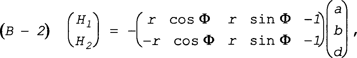
Die obere Scheiben-Einheit 17 steuert
zwei Blätter,
nämlich
das Blatt 11, dessen Azimut im absoluten Bezugssystem Φ = Ωt + φ ist, wobei Ω die Drehgeschwindigkeit
des Rotors und t die Zeit ist, und das Blatt 12, dessen
Azimut Φ2 = Φ + π ist. Die
Höhen der
Füße der Stangen 24 und 25 der
Blätter 11 und 12 sind
H1 und H2.The upper disc unit 17 controls two sheets, namely the sheet 11 , whose azimuth in the absolute reference system is Φ = Ωt + φ, where Ω is the speed of rotation of the rotor and t is time, and the blade 12 whose azimuth Φ 2 = Φ + π. The heights of the feet of the poles 24 and 25 of leaves 11 and 12 are H 1 and H 2 .
Es gilt: wobei r der Radius der drehenden
Scheibe 19 der oberen Scheiben-Einheit 17 ist.The following applies: where r is the radius of the rotating disc 19 the upper disc unit 17 is.
Indem (B-1) und (B-2) kombiniert
werden, ergibt sich: Combining (B-1) and (B-2) results in:
Die untere Einheit 16 steuert
die Blätter 13 und 14 und
es wird vorausgesetzt, dass der Azimut des Blattes 13 ist:
The lower unit 16 controls the leaves 13 and 14 and it is assumed that the azimuth of the leaf 13 is:
In diesem Fall ist die relative Position
des Blattes 13 in Bezug auf die Zylinder 26, 27 und 28,
die mit den Punkten 1', 2', 3' verbunden sind,
die gleiche wie die relative Position des Blattes 11 in
Bezug auf die Zylinder 26, 27 und 29,
die mit den Punkten 1, 2, 3 verbunden
sind.In this case, the relative position of the sheet 13 in terms of cylinders 26 . 27 and 28 that with the dots 1' . 2 ' . 3 ' connected, the same as the relative position of the sheet 11 in terms of cylinders 26 . 27 and 29 that with the dots 1 . 2 . 3 are connected.
Das Blatt 14 hat als Azimut The leaf 14 has as azimuth
Die relative Position des Blattes 14 in
Bezug auf die Zylinder 26, 27 und 28,
die mit den Punkten 1' , 2' , 3' verbunden sind,
ist die gleiche wie die relative Position des Blattes 12 in
Bezug auf die Zylinder 26, 27 und 29,
die mit den Punkten 1, 2, 3 verbunden
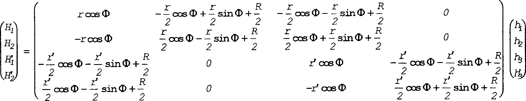
sind. Deswegen leitet sich das System (B-4) unmittelbar vom System
(B-3) ab, indem einfach r in r' umgeändert wird,
wenn die drehende Scheibe 18 der unteren Einheit 16 einen
gegenüber
dem Radius r der drehenden Scheibe 19 unterschiedlichen
Radius r' hat und
wenn H'1 und H'2 die
Höhen der
Füße der Stangen 22 und 23 der
Blätter 13 und 14 sind.The relative position of the sheet 14 in terms of cylinders 26 . 27 and 28 that with the dots 1' . 2 ' . 3 ' connected is the same as the relative position of the sheet 12 in terms of cylinders 26 . 27 and 29 that with the dots 1 . 2 . 3 are connected. Therefore, the system (B-4) derives directly from the system (B-3) by simply changing r to r 'when the rotating disc 18 the lower unit 16 one opposite the radius r of the rotating disc 19 has different radius r 'and when H' 1 and H ' 2 the heights of the feet of the rods 22 and 23 of leaves 13 and 14 are.
In (B-4) ist der Winkel Φ der Winkel
des Blattes 11, das durch die obere Scheiben-Einheit 17 mit
dem Punkt 1 gesteuert wird. Indem (B-3) und (B-4) kombiniert
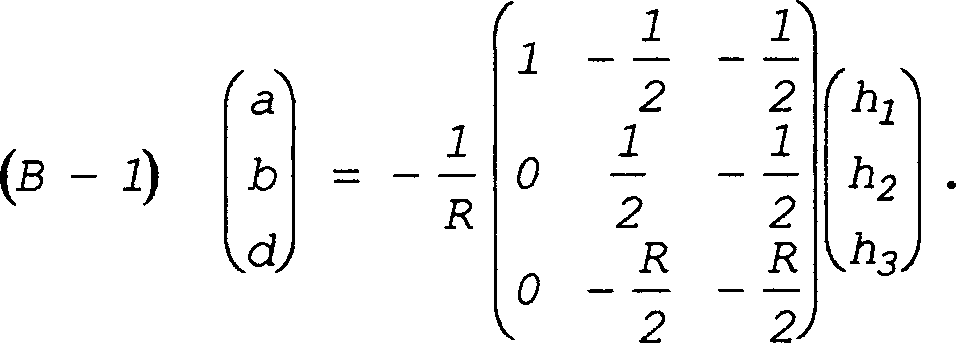
und Beziehungen zwi schen den h und den h' berücksichtigt
werden, ergibt sich schließlich:
(B-5) In (B-4) the angle Φ is the angle of the sheet 11 that through the upper disc unit 17 with the point 1 is controlled. Combining (B-3) and (B-4) and taking into account relationships between the h and the h 'results in the following: (B-5)
Das System (B-5) muss nun invertiert
werden, um einer eineindeutigen Beziehung sicher zu sein, die für eine individuelle
Steuerung der Ansteuerung der Blätter
zwischen den H1, H2,
H'1,
H'2 und
den h1, h2, h3, h'3 nötig
ist. Man erhält: The system (B-5) must now be inverted in order to be sure of a one-to-one relationship which is necessary for individual control of the actuation of the leaves between the H 1 , H 2 , H ' 1 , H' 2 and the h 1 , h 2 , h 3 , h ' 3 is necessary. You get:
In (B-6) ist gesetzt worden: The following has been set in (B-6):
Durch die Gleichungen (B-5) und (B-6)
ist man sich der Gültigkeit
der Konfiguration der 1 sicher, die
eine Vor richtung für
Blätter
mit 180° ist
und für
eine individuelle Steuerung von Blättern mit vollem Einfluss verwendbar
ist, wenn die Zylinder 26 bis 29 am Aufbau 31 des
Hubschraubers gelenkig angebracht sind, aber auch für eine individuelle
Steuerung mit reduziertem Einfluss, wenn diese Zylinder an einer
Sicherheitsscheibe gelenkig angebracht sind, wie nachfolgend unter
Bezugnahme auf die 16 bis 18 beschrieben wird.The equations (B-5) and (B-6) are valid for the configuration of the 1 sure, which is a device for sheets with 180 ° and can be used for individual control of sheets with full influence when the cylinder 26 to 29 on construction 31 of the helicopter are articulated, but also for individual control with reduced influence if these cylinders are articulated on a safety disk, as follows with reference to the 16 to 18 is described.
Die geometrische Konfiguration der 1 ist nicht trivial, denn
andere Konfigurationen sind ausprobiert worden und haben nicht zu
inversiblen Systemen geführt,
wobei diese anderen Konfigurationen es also nicht erlauben, unabhängige beliebige
Bewegungen für
die vier Blätter
zu erreichen, wenn sie paarweise in der Verlängerung zueinander genommen
werden. Umgekehrt eignet sich die Vorrichtung der 1 nicht, wenn die Blätter eines Blätterpaares
mit 90° zueinander
liegen. Zu diesem Zweck genügt
es zu zeigen, dass es für eine
besondere azimutale Position nicht möglich ist, den vier Blättern einen
beliebigen Anstellwinkel zu geben. Wenn durch Hypothese die obere
Scheiben-Einheit 17 die Blätter 14 und 12 steuert
und die untere Scheiben-Einheit 16 die Blätter 13 und 11 steuert,
wobei vorausgesetzt wird, das Blatt 13 steht in der Richtung
der Achse O'x' (siehe 1), ist das Blatt 11 dann
in der Richtung der Achse O'y', das Blatt 14 in
der Richtung der Achse Oy und das Blatt 12 in der zur Achse
Ox entgegengesetzten Richtung. Die Anstellungseinstellung des Blattes 13 wird
durch die Höhe
des Punktes 1' bestimmt,
was auch die Höhe
des Punktes 3 festlegt. Die Anstellungseinstellung des
Blattes 11 wird durch die Höhe des Punktes 2' bestimmt, was
auch die Höhe
des Punktes 1 festlegt. Schließlich wird die Anstellungseinstellung
des Blattes 14 durch die Höhe des Punktes 2 bestimmt
. Die Höhe
der Punkte 1, 2, 3 der oberen, nicht
drehenden Scheibe 21 ist festgelegt und die Ebene dieser
oberen Scheibe 21 ist also vollständig bestimmt, und es bleibt
kein verfügbarer
Freiheitsgrad mehr, um willkürlich
die Anstellungseinstellung des Blattes 12 festzulegen.The geometric configuration of the 1 is not trivial, because other configurations have been tried and have not led to inversible systems, so these other configurations do not allow independent, arbitrary movements to be achieved for the four leaves when they are taken in pairs in an extension of each other. Conversely, the device of the 1 not if the leaves of a pair of leaves are at 90 ° to each other. For this purpose, it suffices to show that it is not possible for a particular azimuthal position to give the four blades any angle of attack. If by hypothesis the upper disc unit 17 the leaves 14 and 12 controls and the lower disc unit 16 the leaves 13 and 11 controls, assuming the sheet 13 stands in the direction of the O'x 'axis (see 1 ), is the sheet 11 then in the direction of the O'y 'axis, the leaf 14 in the direction of the axis Oy and the sheet 12 in the direction opposite to the axis Ox. The sheet's employment setting 13 is determined by the height of the point 1' determines what is also the height of the point 3 sets. The sheet's employment setting 11 is determined by the height of the point 2 ' determines what is also the height of the point 1 sets. Finally, the hiring attitude of the sheet 14 by the height of the point 2 certainly . The amount of points 1 . 2 . 3 the upper, non-rotating disc 21 is set and the level of this top disc 21 is therefore completely determined, and there is no longer any degree of freedom available to arbitrarily adjust the position of the blade 12 set.
In der Vorrichtung der 1 steuert also jede der
beiden drehenden Scheiben 18 und 19 jeweils eines der
beiden Paare von sich diametral gegenüberliegenden Blättern und
die eine 20 der beiden nicht drehenden Scheiben wird durch drei
Zylinder 26, 27 und 28 positioniert,
während
die andere nicht drehende Scheibe 21 durch den vierten
Zylinder 29 und die beiden Stäbe 32 positioniert
wird, welche an die nicht drehende Scheibe 21 die Verschiebungen übertragen,
die an der nicht drehenden Scheibe 20 durch die beiden
Zylinder 26 und 27 gesteuert werden.In the device of the 1 controls each of the two rotating disks 18 and 19 one of the two pairs of diametrically opposed blades and the one 20 of the two non-rotating discs is replaced by three cylinders 26 . 27 and 28 positioned while the other non-rotating disc 21 through the fourth cylinder 29 and the two rods 32 is positioned, which on the non-rotating disc 21 the shifts transmitted to the non-rotating disc 20 through the two cylinders 26 and 27 to be controlled.
Die Prüfung der Gleichungen des Systems
(B-6) zeigt, dass zum Erreichen einer Variation der Anstellung eines
Blattes mit der Frequenz f die Zylinder mit einer Frequenz f' = f + 2f0 arbeiten müssen, wobei f0 die Drehfrequenz
des Rotors ist, was das erforderliche Durchlassband der Zylinder 26 bis
29 im Vergleich zu demjenigen von Zylindern zur individuellen Steuerung
der Blätter
eines Dreiblatt-Rotors wesentlich vergrößert.Examination of the equations of the system (B-6) shows that in order to achieve a variation in the pitch of a blade with the frequency f, the cylinders have to work with a frequency f '= f + 2f 0 , where f 0 is the rotational frequency of the rotor, what the required passband of the cylinders 26 to 29 compared to that of cylinders for individual control of the blades of a three-bladed rotor significantly enlarged.
Die Drehungssperrung der nicht drehenden
Scheiben um die Achse 0z des Rotors kann für die untere Scheibe 20 durch
einen herkömmlichen
gelenkigen Zirkel sichergestellt werden und für die obere Scheibe 21 durch
die Stäbe 32,
die sie mit der unteren Scheibe 20 verbinden, wie nachfolgend
beschrieben und in den Beispielen der 2 bis 4 und 7 und 8 dargestellt
ist.The rotation lock of the non-rotating disks around the axis 0z of the rotor can for the lower disc 20 be ensured by a conventional articulated compass and for the upper disc 21 through the bars 32 they with the lower disc 20 connect as described below and in the examples of 2 to 4 and 7 and 8th is shown.
2 stellt
ein Beispiel einer Vorrichtung gemäß der 1 mit inneren drehenden Scheiben dar. 2 represents an example of a device according to the 1 with inner rotating disks.
Es finden sich wieder die beiden
Verbindungsstäbe 32,
welche die untere, nicht drehende Scheibe 20 und die obere,
nicht drehende Scheibe 21 verbinden und jeweils in der
Verlängerung
der einen 26 bzw. anderen 27 von zwei der drei Zylinder (wobei der
dritte Zylinder in 2 nicht
sichtbar ist) sind, die zwischen dem festen Aufbau 31 des
Hubschraubers und der nicht drehenden Scheibe 20 der unteren
Taumelscheiben-Einheit 16 gelenkig
angebracht sind. Jeder Stab 32 ist wie jeder Zylinder an
seinen drei Enden durch zwei Kugelköpfe 30 oder äquivalente
Mittel gelenkig angebracht. Ebenso ist der vierte Zylinder 29 am
festen Aufbau 31 und an der nicht drehenden Scheibe 21 der
oberen Einheit 17 durch zwei Kugelköpfe 30 gelenkig angebracht. Die
untere 18 und die obere drehende Scheibe 19 sind
drehbar innerhalb der unteren nicht drehenden Scheibe 20 bzw.
der oberen 21 in bekannter Weise mit Hilfe wenigstens eines
Kugellagers angebracht, wie bei 33 für die obere Einheit 17 schematisch
dargestellt ist.The two connecting rods can be found again 32 which is the lower, non-rotating disc 20 and the top, non-rotating disc 21 connect and each in the extension of one 26 or another 27 of two of the three cylinders (the third cylinder in 2 is not visible) that are between the solid structure 31 of the helicopter and the non-rotating disc 20 the lower swashplate unit 16 are articulated. Every staff 32 is like every cylinder at its three ends by two ball heads 30 or equivalent means articulated. The same is the fourth cylinder 29 on solid construction 31 and on the non-rotating disc 21 the upper unit 17 by two ball heads 30 articulated attached. The lower one 18 and the top rotating disc 19 are rotatable within the lower non-rotating disc 20 or the upper one 21 attached in a known manner with the help of at least one ball bearing, as in 33 for the upper unit 17 is shown schematically.
In 2 umfasst
jede drehende Scheibe 18 oder 19 eine Felge 18a oder 19a,
die durch Speichen 18b oder 19b mit einer Nabe 18c oder 19c verbunden
ist, die auf einem zentralen Kugelkopf 34 schwingt, der
axial verschieblich um eine Muffe 35 angebracht ist, die
den Rotormast 10 umgreift und auch am Aufbau 31 befestigt ist.In 2 encompasses each rotating disc 18 or 19 a rim 18a or 19a by spokes 18b or 19b with a hub 18c or 19c connected to a central ball head 34 swings, which is axially displaceable around a sleeve 35 attached to the rotor mast 10 embraces and also on the structure 31 is attached.
Die gelenkige Anbringung einer drehenden
Scheibe an einem zentralen Kugelkopf 34 ist in 5 für die untere drehende Scheibe 18 dargestellt.
Der Kugelkopf 34, der an der Muffe 35 bei einer
Konfiguration von Blättern
mit 180° verschieblich
ist, ist von einem Kranz 36 umfasst, der mit dem Kugelkopf 34 durch
eine konkave und kugelförmige,
innere Auflagefläche
zusammenwirkt und ein Kugellager (nicht dargestellt) trägt, das zwischen
dem Kranz 36 und der Nabe 18c der unteren drehenden
Scheibe 18a eingefügt
ist.The articulated attachment of a rotating disc to a central ball head 34 is in 5 for the lower rotating disc 18 shown. The ball head 34 who on the sleeve 35 with a configuration of leaves that can be moved by 180 ° is from a wreath 36 includes the one with the ball head 34 cooperates through a concave and spherical inner bearing surface and carries a ball bearing (not shown) which is between the rim 36 and the hub 18c the lower rotating disc 18a is inserted.
Die durchbrochene Struktur der oberen
drehenden Scheibe 19 erlaubt es den zwei Stangen 22 und 23,
die an der unteren drehenden Scheibe 18 gelenkig angebracht
sind, die begrenzten Öffnungen
zwischen den Speichen 19b der oberen drehenden Scheibe 19 ohne
störende
mechanische Beeinflussung dieser letzteren zu durchlaufen, da die
drehenden Scheiben 18 und 19 und somit die Stangen 22 bis 25 mit
der gleichen Geschwindigkeit wie der Rotor und seine Blätter drehen.
Da aber die drehenden Scheiben 18 und 19 im wesentlichen
den gleichen Durchmesser haben, sind die durch die untere drehende
Scheibe 18 angetriebenen Stangen 22 und 23 nicht
mehr geradlinig, sondern weisen eine Form auf, die an den Verlauf
quer durch die drehende Scheibe 19 im Gegensatz zu den
Stangen 24 und 25 angepasst ist, die geradlinig
sind und durch Kugelköpfe 37 an
dieser oberen drehenden Scheibe 19 gelenkig angebracht
sind. Auf Grund ihrer nicht geradlinigen Form sind die Stangen 22 und 23 an
der unteren drehenden Scheibe 18 durch Mittel gelenkig
angebracht, die jegliche Drehung um eine zu dieser Scheibe 18 senkrechten
Achse verbieten, also nicht durch einen Kugelkopf, sondern z. B.
durch ein Kardangelenk 38.The openwork structure of the upper rotating disc 19 allow the two poles 22 and 23 that on the lower rotating disc 18 are hinged, the limited openings between the spokes 19b the top rotating disc 19 to pass through the latter without disturbing mechanical interference, since the rotating disks 18 and 19 and thus the poles 22 to 25 rotate at the same speed as the rotor and its blades. But there are the rotating disks 18 and 19 are of substantially the same diameter are those through the lower rotating disc 18 driven rods 22 and 23 no longer rectilinear, but have a shape that follows the course across the rotating disc 19 unlike the poles 24 and 25 is adapted that are straight forward and through ball heads 37 on this top rotating disc 19 are articulated. Because of their non-linear shape, the poles are 22 and 23 on the lower rotating disc 18 articulated by means of any rotation about one to this disc 18 prohibit vertical axis, so not by a spherical head, but z. B. by a universal joint 38 ,
Durch die Wahl einer beliebigen,
aber geeigneten Form der an der unteren drehenden Scheibe gelenkig
angebrachten Stangen kann man somit die Durchmesser der drehenden
Scheiben frei wählen.By choosing any
but suitable form of articulated on the lower rotating disc
attached rods can thus be the diameter of the rotating
Choose slices freely.
Der Drehantrieb der drehenden Scheiben 18 und 19 wird
durch einen gelenkigen Doppelzirkel 39 sichergestellt,
der einen oberen Teil enthält,
der die obere drehende Scheibe 19 antreibt und aus einer
Gabel 40 gebildet ist, die um eine den Rotormast 10 durchquerende
Durchmesserachse schwenkbar ist und deren Stiel in 41 in einer zweiten
Gabel 42 schwenkbar gelenkig angebracht ist, die durch
ihren Stiel mit Hilfe eines Kugelkopfes 43 an der drehenden
Scheibe 19 gelenkig angebracht ist. Der Doppelzirkel 39 umfasst
auch einen unteren Teil mit einer Gabel 44, die schwenkbar
am Stiel der Gabel 40 angebracht ist und deren Stiel 45 seinerseits
schwenkbar in einer weiteren Gabel 46 schwenkbar ist, die
ihrerseits durch ihren Arm 47 an der unteren drehenden
Scheibe 18 durch einen Kugelkopf 48 gelenkig angebracht
ist. Die Kugelköpfe 43 und 48 zur gelenkigen
Anbringung des Antriebs-Doppelzirkels 39 an den drehenden
Scheiben 18 und 19 stellen jeweils eine Drehungsfreiheit
entsprechend zwei Achsen sicher, die parallel zur Ebene der entsprechenden
drehenden Scheibe verlaufen.The rotary drive of the rotating disks 18 and 19 is by an articulated double circle 39 ensured that an upper part contains the upper rotating disc 19 drives and from a fork 40 is formed around a the rotor mast 10 traversing diameter axis is pivotable and the stem in 41 in a second fork 42 is pivotally articulated by its stem with the help of a ball head 43 on the rotating disc 19 is articulated. The double circle 39 also includes a lower part with a fork 44 who can pivot on the stem of the fork 40 is attached and their stem 45 in turn swiveling in another fork 46 is pivotable, which in turn by her arm 47 on the lower rotating disc 18 through a ball head 48 is articulated. The ball heads 43 and 48 for articulated attachment of the double drive compass 39 on the rotating disks 18 and 19 each ensure freedom of rotation according to two axes that run parallel to the plane of the corresponding rotating disc.
Die Halterung der beiden nicht drehenden
Scheiben 20 und 21 wird mittels eines gelenkigen
Antirotationszirkels 49 sichergestellt, der in 7 genauer dargestellt ist.
Dieser Zirkel 49 umfasst zwei Äste 49a und 49b,
die als Gabeln gestaltet sind und zueinander schwenkbar an einer
Schwenkachse 50 angebracht sind, wobei der untere Ast 49a auch
um eine Schwenkachse 51, die zur Schwenkachse 50 parallel
ist, an einem Beschlag 52 schwenkbar gelagert ist, der
mit dem festen Aufbau 31 fest verbunden ist. Der obere
Ast 49b ist auch, so wie das untere, als Gabel 32a ausgebildete
Ende eines Stabes 32, an der zur Schwenkachse 51 parallelen
Traverse 53a einer "T"-Schwenkachse 53 schwenkbar
angebracht, deren Fuß 53b um
ihre in Bezug auf den Rotormast 10 radiale Längsachse
in einer mit der unteren, nicht drehenden Scheibe 20 fest
verbundenen Muffe 54 schwenkbar ist. Das obere Ende der
Stange des Zylinders 26 ist auch als Gabel 26a ausgebildet,
die um die Traverse 53a der "T"-Schwenkachse
53 schwenkbar ist. Diese Anbringung erlaubt das Benutzen des Stabes 32,
der durch einen Kugelkopf 30 an seinem oberen Ende an der
oberen, nicht drehenden Scheibe 21 gelenkig angebracht
ist, als dem Zirkel 49 zugeordnetes Antirotationsmittel,
um die beiden nicht drehenden Scheiben 20 und 21 festzuhalten.The bracket of the two non-rotating disks 20 and 21 is by means of an articulated anti-rotation circle 49 ensured the in 7 is shown in more detail. This circle 49 comprises two branches 49a and 49b , which are designed as forks and pivotable to each other on a pivot axis 50 are attached, the lower branch 49a also around a swivel axis 51 going to the swivel axis 50 is parallel to a fitting 52 is pivotally mounted with the fixed structure 31 is firmly connected. The upper branch 49b is also, like the lower one, a fork 32a trained end of a rod 32 , on the swivel axis 51 parallel traverse 53a a "T" swivel axis 53 pivotally attached, the foot 53b to their in terms of the rotor mast 10 radial longitudinal axis in a with the lower, non-rotating disc 20 firmly connected sleeve 54 is pivotable. The top end of the rod of the cylinder 26 is also a fork 26a trained around the traverse 53a the "T" pivot axis 53 is pivotable. This attachment allows the rod to be used 32 by a ball head 30 at its upper end on the upper, non-rotating disc 21 is articulated than the compass 49 assigned anti-rotation means to the two non-rotating disks 20 and 21 hold.
Selbstverständlich kann man einen herkömmlichen,
gelenkigen Antirotationszirkel dazu verwenden, um jede der beiden
nicht drehenden Scheiben 20 und 21 festzuhalten,
und man kann zwei herkömmliche,
gelenkig Zirkel dazu verwenden, um durch jeweils einen von ihnen
die eine bzw. die andere von zwei drehenden Scheiben 18 und 19 anzutreiben,
auf Kosten eines größeren Platzbedarfes,
da der Zirkel zum Antrieb der unteren drehenden Scheibe 18 wenigstens
einen Arm haben muss, der genügend
lang ist, um am Rotormast 10 oberhalb der Muffe 35 gelenkig
verbunden zu werden.Of course, a conventional, articulated anti-rotation compass can be used to attach each of the two non-rotating disks 20 and 21 and two conventional, articulated compasses can be used to pass one or the other of two rotating disks through each of them 18 and 19 to drive, at the cost of a larger space requirement, since the compass for driving the lower rotating disc 18 must have at least one arm that is long enough to hold the rotor mast 10 above the sleeve 35 to be articulated.
3 ist
eine Variante der Vorrichtung für
Blätter
mit 180° der 1, bei der die untere drehende Scheibe 18' und die obere
drehende Scheibe 19' außerhalb
sind und um die entsprechende untere, nicht drehende Scheibe 20' oder obere,
nicht drehende Scheibe 21' drehen. 3 is a variant of the device for sheets with 180 ° 1 , where the lower rotating disc 18 ' and the top rotating disc 19 ' are outside and around the corresponding lower, non-rotating disc 20 ' or upper, non-rotating disc 21 ' rotate.
Jede der nicht drehenden Scheiben 20' und 21' ist um den
Rotormast 10 schwingend und parallel zu diesem Mast verschieblich
mittels eines zentralen Kugelkopfes 34 angebracht, der
axial um die den Mast 10 umgreifende, feste Muffe 35 verschiebbar
ist und an dem die Scheibe 20' oder 21' durch ihre Nabe 20'c oder 21'c schwingend
direkt angebracht ist, wobei die Einfügung eines Kranzes und wenigstens
eines Wälzlagers zwischen
den Kugelkopf und die Nabe der Scheibe, wie vorstehend unter Bezugnahme
auf 5 beschrieben wurde,
freiwillig wird, weil die betroffene Scheibe nicht drehend ist.Any of the non-rotating disks 20 ' and 21 ' is about the rotor mast 10 swinging and displaceable parallel to this mast by means of a central ball head 34 attached axially around the mast 10 encompassing, firm sleeve 35 is movable and on which the disc 20 ' or 21 ' through her hub 20'c or 21'c is mounted directly swinging, the insertion of a ring and at least one roller bearing between the ball head and the hub of the disc, as described above with reference to 5 has been described, because the disk in question is not rotating.
Die sich diametral gegenüberliegenden
und durch die untere drehende Scheibe 18' angetriebenen Stangen 22' und 23' sind nicht
geradlinig, wie das auch im vorhergehenden Beispiel der Fall ist,
sondern sind in diesem Beispiel verformt, um außerhalb der oberen Taumelscheiben-Einheit 17' zu verlaufen,
deren Durchmesser im wesentlichen der gleiche ist wie derjenige
der unteren Taumelscheiben-Einheit 16', während die sich diametral gegenüberliegenden
und durch den Kugelkopf an der oberen drehenden Scheibe 19' angetriebenen
Stangen 24' und 25' geradlinig
sind. Aus diesen Gründen
und wie in 2 sind die
nichtgeradlinigen Stangen 22' und 23' mit der unteren
drehenden Scheibe 18' durch
Kardane gelenkig verbunden.The diametrically opposite and through the lower rotating disc 18 ' driven rods 22 ' and 23 ' are not straightforward, as is the case in the previous example, but are deformed in this example to outside the upper swashplate unit 17 ' to run, whose diameter is substantially the same as that of the lower swash plate unit 16 ' while the diametrically opposite and through the ball head on the upper rotating disc 19 ' driven rods 24 ' and 25 ' are straightforward. For these reasons and as in 2 are the non-rectilinear poles 22 ' and 23 ' with the lower rotating disc 18 ' articulated by gimbals.
Wie in 2 wird
der Drehantrieb der drehenden Scheiben 18' und 19' vom Mast 10 aus und oberhalb der
Muffe 35 durch einen gelenkigen Doppelzirkel 39' sichergestellt,
dessen oberer Teil eine Gabel 40' enthält, die um eine den Mast 10 durchquerende
Durchmesserachse schwenkbar ist und in 41' schwenkbar gelenkig in einer zweiten
Gabel 42' angebracht
ist, die durch ihren Stiel mittels eines Kugelkopfes 43' an der oberen drehenden
Scheibe 19' gelenkig
angebracht ist. Der andere Teil des Zirkels 39', der die untere
drehende Scheibe 18' antreibt,
umfasst auch zwei Gabeln 44' und 46', die außerhalb
der oberen Taumelscheiben-Einheit 17' verlaufen und von denen die erste 44' am Stiel der
Gabel 40' um
eine Schwenkachse 45' außerhalb
der Gabel 42' und
die zweite 46' durch
ein Kugelgelenk 48' an
der unteren drehenden Scheibe 18' gelenkig angebracht ist, wobei
die Gabeln 44' und 46' auch miteinander
um die Schwenkachse 47' bei
Schwenkbarkeit gelenkig verbunden sind.As in 2 becomes the rotary drive of the rotating disks 18 ' and 19 ' from the mast 10 from and above the sleeve 35 through an articulated double circle 39 ' ensured whose upper part is a fork 40 ' contains that around a the mast 10 traversing diameter axis is pivotable and in 41 ' articulated in a second fork 42 ' is attached by its stem by means of a ball head 43 ' on the top rotating disc 19 ' is articulated. The other part of the circle 39 ' which is the lower rotating disc 18 ' drives also includes two forks 44 ' and 46 ' that are outside the upper swashplate unit 17 ' run and of which the first 44 ' on the stick of the fork 40 ' about a pivot axis 45 ' outside the fork 42 ' and the second 46 ' through a ball joint 48 ' on the lower rotating disc 18 ' is articulated, with the forks 44 ' and 46 ' also with each other around the swivel axis 47 ' are articulated when pivotable.
Die beiden nicht drehenden Scheiben 20' und 21' können ringförmige Vollscheiben
sein, außer
der inneren Scheibe 20',
die wenigstens zwei Öffnungen
aufweist, davon die eine 20'a für den Durchgang
des einzigen Zylinders 29',
der durch Kugelköpfe 30 direkt
unter der oberen, nicht drehenden Scheibe 21' und am festen Aufbau 31 gelenkig
angebracht ist. Die andere Öffnung 20'b der Scheibe 20' nimmt die Gelenke
an dieser Scheibe 20' von
dem einem 26' der
drei Zylinder zur Steuerung dieser Scheibe 20' sowie einen
der drei Stäbe 32,
die diese Scheibe 20' mit
der anderen nicht drehenden Scheibe 21' verbinden, unter welcher dieser
Stab 32 durch einen Kugelkopf 30 gelenkig angebracht
ist, und von einem Antirotationszirkel 49' auf, der durch den später unter
Bezugnahme auf die
8 und 8a beschriebenen Aufbau
ersetzt werden kann, entsprechend einer Variante der 7 und unter Verwendung dieses
Stabes 32 als Antirotationsmittel.The two non-rotating disks 20 ' and 21 ' can be ring-shaped solid disks, except for the inner disk 20 ' , which has at least two openings, one of which 20'a for the passage of the single cylinder 29 ' by ball heads 30 directly under the upper, non-rotating disc 21 ' and on solid construction 31 is articulated. The other opening 20'b the disc 20 ' takes the joints off this disc 20 ' from the one 26 ' the three cylinders to control this disc 20 ' and one of the three bars 32 who this disk 20 ' with the other non-rotating disc 21 ' connect under which this rod 32 through a ball head 30 is articulated, and by an anti-rotation circle 49 ' on by the later referring to the 8th and 8a described structure can be replaced, according to a variant of 7 and using this rod 32 as an anti-rotation agent.
Die beiden anderen Zylinder 27' und 28' zur Steuerung
der Scheibe 20' sind
am festen Aufbau 31 sowie unter der Scheibe 20' durch Kugelköpfe 30 gelenkig
angebracht und der Gelenkpunkt unter der Scheibe 20' des Zylinders 27' ist direkt
unter dem zweiten Stab 32, der durch Kugelköpfe 30 an
dieser Scheibe 20' und unter
der oberen, nicht drehenden Scheibe 21' gelenkig angebracht ist.The other two cylinders 27 ' and 28 ' to control the disc 20 ' are at the solid construction 31 as well as under the pane 20 ' through ball heads 30 articulated and the hinge point under the disc 20 ' of the cylinder 27 ' is right under the second stick 32 by ball heads 30 on this disc 20 ' and under the top, non-rotating disc 21 ' is articulated.
8 zeigt,
dass der Antirotationszirkel 49' der 3,
dessen unterer Gabelast 49'a durch
seinen Fuß in
einem mit dem festen Aufbau 31 fest verbundenen "U"-Beschlag 52' geschwenkt wird, einen Aufbau
haben kann und montiert werden kann wie der Zirkel 49 der 7. Es findet sich wiederum,
dass das als Gabel ausgebildete Ende 26'a des Zylinders 26' sowie das untere,
als Gabel ausgebildete Ende 32a des Stabes 32 und die
Gabel des oberen Astes 49b des Zirkels 49 um eine gleiche
Achse 53'a schwenkbar
angebracht sind, die in einer Bohrung einer Quernabe 53'c (siehe 8a) eines Querstückes 53' untergebracht
ist, das quer durch die Öffnung 20'b der Scheibe 20' durch seine
Längsarme 53'b aufgehängt ist,
die Torsionsarme sind, die eine Drehung um ihre Längsachse
zulassen, die in Bezug auf die Achse des Rotors radial ist. 8a zeigt ein Beispiel zur
Befestigung durch ihre Enden der torsiblen Arme 53'b des Querstücks 53' in begrenzten
Aufnahmen zum Teil in der oberen Fläche der nicht drehenden Scheibe 20' und zum Teil
in der unteren Fläche
von zwei an der Scheibe 20' verschraubten
und die Enden der Arme 53'b gegen
diese Scheibe 20' einklemmenden
Stützen 54'. 8th shows that the anti-rotation circle 49 ' the 3 , whose lower fork load 49'a through his foot in one with the solid structure 31 firmly connected "U" fitting 52 ' is pivoted, can have a structure and can be assembled like a compass 49 the 7 , It is again found that the end designed as a fork 26'a of the cylinder 26 ' and the lower end, designed as a fork 32a of the staff 32 and the fork of the upper branch 49b of the compass 49 about the same axis 53'a are pivotally mounted in a bore of a transverse hub 53'c (please refer 8a ) of a cross piece 53 ' which is housed across the opening 20'b the disc 20 ' through its longitudinal arms 53'b which are torsion arms which allow rotation about their longitudinal axis which is radial with respect to the axis of the rotor. 8a shows an example of attachment by their ends of the torso arms 53'b of the crosspiece 53 ' in limited shots partly in the upper surface of the non-rotating disc 20 ' and partly in the lower surface of two on the disc 20 ' screwed and the ends of the arms 53'b against this disc 20 ' jamming supports 54 ' ,
Bei dieser Anbringung lässt man
auch einen der Stäbe 32 zur
Verbindung zwischen den beiden nicht drehenden Scheiben 20' und 21' eine Gegenmoment-
oder Gegenrotationsrolle für
die nicht drehende Scheibe 21' spielen.With this attachment you also leave one of the rods 32 for the connection between the two non-rotating disks 20 ' and 21 ' a counter-torque or counter-rotation roller for the non-rotating disc 21 ' play.
Dies kann vermieden werden, wenn
der Antirotationsdoppelzirkel der 9 anstelle
des Zirkels 49 oder 49' und eines Stabes 32 der 3 und 8 übernommen
wird. In diesem Fall ist der Antirotationsdoppelzirkel der 9 mit der unteren, nicht
drehenden Scheibe 20' mittels
eines Querstücks 53' gelenkig verbunden, das
identisch zu demjenigen der 8 ist
und in gleicher Weise in einer Öffnung 20'd der Scheibe 20' anstelle des
an dieser Scheibe 20'd vorhandenen
Gelenks 30 des dritten Zylinders 28' angebracht ist, dessen Wirkung durch
einen Verbindungsstab wie z. B. 32 nicht verlängert wird.This can be avoided if the anti-rotation double circle 9 instead of the circle 49 or 49 ' and a staff 32 the 3 and 8th is taken over. In this case the anti-rotation double circle is the 9 with the lower, non-rotating disc 20 ' by means of a cross piece 53 ' articulated, identical to that of the 8th and in the same way in an opening 20'd the disc 20 ' instead of that on this disc 20'd existing joint 30 of the third cylinder 28 ' is attached, the effect of a connecting rod such. B. 32 is not extended.
Der Antirotationsdoppelzirkel der 9 umfasst einen unteren
Zirkel, der in seinem Aufbau und seiner Anbringung identisch zum
Zirkel 49 der 8 ist
und durch die Gabel seines oberen Astes 49b um die quer verlaufende
Schwenkachse 53'a des
Querstücks 53' gleichzeitig
wie eine Gabel 28'a des
oberen Endes der Stange des Zylinders 28' und wie die Gabel des unteren
Astes 55a eines oberen gelenkigen Zirkels 55 schwenkbar
angebracht ist, der auch einen oberen Ast 55b umfasst,
der durch den Kugelkopf 30 unter der oberen, nicht drehenden
Scheibe 21' gelenkig
angebracht und als Gabel ausgelegt ist, in der der untere Ast 55a um
eine Schwenkachse 55c schwenkt, die parallel zur Schwenkachse 53'a des Querstücks 53' verläuft. Der obere
Zirkel 55 des Antirotationsdoppelzirkels hält die obere,
nicht drehende Scheibe 21' in
Bezug auf die untere, nicht drehende Scheibe 20' fest, welche
drehungsmäßig durch
den unteren Zirkel 49 festgehalten wird, der sie mit dem
festen Aufbau 31 verbindet.The anti - rotation double circle of 9 includes a lower circle, which is identical in structure and attachment to the circle 49 the 8th and through the fork of its upper branch 49b about the transverse pivot axis 53'a of the crosspiece 53 ' at the same time like a fork 28'a the upper end of the rod of the cylinder 28 ' and like the fork of the lower branch 55a of an upper articulated circle 55 is pivotally attached, which also has an upper branch 55b includes that through the ball head 30 under the upper, non-rotating disc 21 ' articulated and designed as a fork in which the lower branch 55a about a pivot axis 55c pivots parallel to the swivel axis 53'a of the crosspiece 53 ' runs. The upper circle 55 of the anti-rotation double circle holds the upper, non-rotating disc 21 ' in relation to the lower, non-rotating disc 20 ' firmly, which rotates through the lower circle 49 is held on to them with the solid structure 31 combines.
Der Antirotationsdoppelzirkel der 9 kann auch an den Vorrichtungen
mit wenigstens einer Taumelscheiben-Einheit mit Zentrumsfixierung
verwendet werden, deren Art später
unter Bezugnahme auf die 10 bis 12 beschrieben wird.The anti - rotation double circle of 9 can also on the devices with at least one wobble disc unit with center fixation can be used, the type of which will be referred to later 10 to 12 is described.
4 stellt
eine weitere Variante der Vorrichtung der 1 dar, bei der die obere Taumelscheiben-Einheit
identisch zu derjenigen 17 der 2 ist
und eine durchbrochene drehende Scheibe 19 umfasst, die
durch ihre Nabe 19c an einem zentralen Kugelkopf 34 schwingend
ist, der um eine feste Muffe 35 verschieblich ist. Diese
drehbare Scheibe 19 ist durch Kugelköpfe 37 an zwei sich
diametral gegenüberliegenden
und geradlinigen Anstellungsstangen 24 und 25 gelenkig
angebracht und mittels eines Lagers 33 im Inneren einer
nicht drehenden Scheibe 21 drehbar angebracht, die durch
einen einzigen Zylinder 29, der durch Kugelköpfe 30 zwischen
der Scheibe 21 und dem festen Aufbau 31 gelenkig
angebracht ist, und durch zwei Verbindungsstäbe 32 gesteuert wird,
die sie mit der nicht drehenden Scheibe der unteren Taumelscheiben-Einheit 16'' verbinden, die eine äußere drehende
Scheibe 18'', die um eine
innere, nicht drehende Scheibe 20" drehbar ist, in Form einer Vollscheibe
enthält,
die durch ihre Nabe 20''c an einem weiteren
Kugelkopf 34 gelenkig angebracht ist, der um die feste
Muffe 35 axial verschiebbar ist. 4 represents a further variant of the device of the 1 represents, in which the upper swash plate unit identical to that 17 of the 2 and a broken rotating disc 19 includes that through her hub 19c on a central ball head 34 is swinging around a fixed sleeve 35 is movable. This rotating disc 19 is through ball heads 37 on two diametrically opposite and straight-line adjustment rods 24 and 25 articulated and by means of a bearing 33 inside a non-rotating disc 21 rotatably attached by a single cylinder 29 by ball heads 30 between the disc 21 and the solid structure 31 is articulated, and by two connecting rods 32 it is controlled with the non-rotating disc of the lower swashplate unit 16 '' connect that an outer rotating disc 18 '' that are around an inner, non-rotating disc 20 " is rotatable, contains in the form of a solid disc through its hub 20''c on another ball head 34 is articulated around the fixed sleeve 35 is axially displaceable.
Wie in 2 sind
die beiden anderen, sich diametral gegenüberliegenden Stangen 22 und 23 nichtgeradlinig
und nach innen verformt, um in Öffnungen
der oberen drehenden Scheibe 19 zu verlaufen, und sind mit
der unteren drehenden Scheibe 18'' durch
Kardane 38 gelenkig verbunden.As in 2 are the other two diametrically opposed rods 22 and 23 non-rectilinear and deformed inward in openings of the upper rotating disc 19 to run, and are with the lower rotating disc 18 '' through gimbals 38 articulated.
Wie in 2 ist
der Drehantrieb der inneren oberen drehenden Scheibe 19 und
der äußeren unteren drehenden
Scheibe 18'' durch einen
gelenkigen Doppelzirkel 39 sichergestellt, der in seinem
Aufbau und seiner Anbringung zu demjenigen identisch ist, der unter
Bezugnahme auf 2 beschrieben
wurde. Dieser Doppelzirkel 39 ist also bei Schwenkbarkeit
am Rotormast
10 durch einen Kugelkopf 43 an der
oberen drehenden Scheibe 19 und durch einen Kugelkopf 48 an
der unteren drehenden Scheibe 18'' gelenkig
angebracht.As in 2 is the rotary drive of the inner upper rotating disc 19 and the outer lower rotating disc 18 '' through an articulated double circle 39 ensured that its structure and its attachment are identical to those with reference to 2 has been described. This double circle 39 is so with pivoting on the rotor mast 10 through a ball head 43 on the top rotating disc 19 and through a ball head 48 on the lower rotating disc 18 '' articulated attached.
Um die Anbringung der drei Zylinder
zur Schrägstellung
und Längsverschiebung
der unteren Einheit 16'' zu vereinfachen,
von denen nur zwei Zylinder 26 und 27 in 4 sichtbar sind, ist die
untere und innere, nicht drehende Scheibe 20'' unter
der unteren drehenden Scheibe 18" durch drei Arme 56 radial
verlängert, an
deren Ende die drei Zylinder und für die beiden in 4 sichtbaren Arme 56 auch
die Verbindungsstäbe 32 an
der oberen, nicht drehenden Scheibe 21 gelenkig angebracht
sind.To attach the three cylinders for inclination and longitudinal displacement of the lower unit 16 '' to simplify, of which only two cylinders 26 and 27 in 4 visible is the lower and inner, non-rotating disc 20 '' under the lower rotating disc 18 " through three arms 56 radially extended, at the end of the three cylinders and for the two in 4 visible arms 56 also the connecting rods 32 on the upper, non-rotating disc 21 are articulated.
Wie in 2 umfassen
auch die Antirotationsmittel der nicht drehenden Scheiben 20'' und 21 einen gelenkigen
Zirkel, der identisch zum Zirkel 49 der 2 ist, und einen Stab 32 entsprechend
einer Anbringung, die identisch zu derjenigen der 7 ist, lediglich mit dem Unterschied,
dass die den Fuß der "T"-Schwenkachse 53 aufnehmende
Muffe 54 mit dem äußeren radialen
Ende des entsprechenden Armes 56 der unteren, nicht drehenden
Scheibe 20" fest
verbunden ist.As in 2 also include the anti-rotation means of the non-rotating disks 20 '' and 21 an articulated circle that is identical to the circle 49 the 2 is, and a staff 32 according to an attachment that is identical to that of the 7 is, with the difference that the foot of the "T" pivot axis 53 receiving sleeve 54 with the outer radial end of the corresponding arm 56 the lower, non-rotating disc 20 " is firmly connected.
Wenn eine der drehenden Scheiben
innerhalb einer nicht drehenden Scheibe drehbar ist, wie für die beiden
drehenden Scheiben 18 und 19 der 2 und die obere drehende Scheibe 19 der 4, kann man anstelle der
schwingenden Anbringung der Nabe einer drehenden Scheibe an einem
verschieblichen zentralen Kugelkopf entsprechend der 5 die Anbringungsvariante
der 6 verwenden, die
eine Schnittansicht ist. Bei dieser Anbringung ist die Muffe 35,
die sich nicht dreht und ohne Berührung den Rotormast 10 umgreift und
drehbar um die Drehachse Oz des Rotors angebracht ist, ihrerseits
von einem Kranz 57 umfasst, der axial um die feste Muffe 35 verschoben
werden kann. Im Bedarfsfall lässt
sich jegliche Dreh bewegung des Kranzes 57 um die Muffe 35 verhindern,
indem der Muffe 35 wenigstens örtlich eine nichtzylindrische
Form gegeben wird oder mittels einer Rille wenigstens in der Muffe 35 oder
auch mit Hilfe anderer Antirotationsmittel am Kranz 57.
Zwei radiale Wangen 58 sind an den axialen Enden des Kranzes 57 befestigt
und werden zum Absorbieren der vertikalen Kräfte belastet, die durch die
entsprechenden Taumelscheiben erzeugt werden. Der Kugelkopf 34' ist um den
Kranz 57 herum und zwischen den Wangen 58 angebracht.
Zwei Wälzlager 59 mit
Kugeln oder zylindrischen Nadeln sind zwischen dem Kranz 57 und
dem Kugelkopf 34' eingefügt und können möglicherweise
durch ein einziges Lager 59 ersetzt werden. Zwei Wälzlager 60 mit
Kugeln oder konischen Rollen sind zwischen dem Kugelkopf 34' und den Wangen 59 eingefügt. Die
Nabe 19'c einer
inneren drehenden Scheibe 19' weist
eine innere ringförmige
Auflagefläche
von konkaver und sphärischer
Form als Abstützung
gegen die äußere sphärische Oberfläche des
Kugelkopfes 34' auf.
In der Richtung der Drehung um die Achse Oz des Rotors ist der Kugelkopf 34' Reibungskräften von
Seiten der drehenden Scheibe 19' ausgesetzt. Er ist auch einem
Reibungsmoment von Seiten der Wälzlager 59 und 60 ausgesetzt.
Aber da die auf die drehende Scheibe 19' zurückzuführenden Reibungen viel erheblicher
sind als jene, die auf die Wälzlager 59 und 60 zurückzuführen sind,
wird der Kugelkopf 34' eine
Drehgeschwindigkeit haben, die fast gleich mit derjenigen der drehenden
Scheibe 19' ist.
Dies verringert den mechanischen Verschleiß zwischen diesen beiden Teilen
beträchtlich. Der
Unterschied zwischen den Geschwindigkeiten dieser beiden Teile kann
durch einen herkömmlich
aufgebauten, gelenkigen Gegenmoment-Zirkel, der zwischen dem Kugelkopf 34' und der drehenden
Scheibe 19' angebracht
sein kann, ganz und gar zum Verschwinden gebracht werden. Als Variante
kann ein elastisch verformbares Verbindungsorgan diese homokinetische
Kupplung sicherstellen. Diese Anbringung erlaubt die Drehung der
drehenden Scheibe 19' um die
Achse Oz des Rotors, wobei die Schwingungsbewegungen dieser drehenden
Scheibe 19' am
Kugelkopf 34' akzeptiert
werden.If one of the rotating disks is rotatable within a non-rotating disk, as for the two rotating disks 18 and 19 the 2 and the top rotating disc 19 the 4 , instead of the oscillating attachment of the hub of a rotating disc to a movable central ball head according to the 5 the mounting variant of the 6 use which is a sectional view. With this attachment is the sleeve 35 that does not turn and without touching the rotor mast 10 engages and rotatably attached to the axis of rotation Oz of the rotor, in turn by a ring 57 includes the axially around the fixed sleeve 35 can be moved. If necessary, any rotary movement of the ring 57 around the sleeve 35 prevent by the sleeve 35 a non-cylindrical shape is given at least locally or at least in the sleeve by means of a groove 35 or with the help of other anti-rotation agents on the wreath 57 , Two radial cheeks 58 are at the axial ends of the wreath 57 attached and are loaded to absorb the vertical forces generated by the corresponding swash plates. The ball head 34 ' is around the wreath 57 around and between the cheeks 58 appropriate. Two roller bearings 59 with balls or cylindrical needles are between the wreath 57 and the ball head 34 ' inserted and can possibly be through a single stock 59 be replaced. Two roller bearings 60 with balls or conical rollers are between the ball head 34 ' and cheeks 59 inserted. The hub 19'c an inner rotating disc 19 ' has an inner annular support surface of concave and spherical shape as a support against the outer spherical surface of the ball head 34 ' on. In the direction of rotation around the axis Oz of the rotor is the spherical head 34 ' Frictional forces on the part of the rotating disc 19 ' exposed. It is also a frictional moment on the part of the rolling bearings 59 and 60 exposed. But since that on the rotating disc 19 ' attributable friction are much more significant than those on the rolling bearings 59 and 60 are the ball head 34 ' have a rotational speed that is almost equal to that of the rotating disc 19 ' is. This significantly reduces the mechanical wear between these two parts. The difference between the speeds of these two parts can be due to a conventionally constructed, articulated counter-torque circuit, which is located between the ball head 34 ' and the rotating disc 19 ' can be appropriate, made to disappear entirely. As a variant, an elastically deformable connecting element can ensure this homokinetic coupling. This attachment allows the rotating disc to rotate 19 ' around the axis Oz of the rotor, the vibrational movements of this rotating disc 19 ' on the ball head 34 ' be accepted.
Die erfindungsgemäße Vorrichtung zur individuellen
Steuerung der Anstellung der Blätter
eines Rotors mit zumindest vier Blättern kann auch wenigstens
zwei Taumelscheiben-Einheiten umfassen, die eine drehbar an einer
nicht drehenden Scheibe angebrachte, drehende Scheibe haben und
in jeder Richtung um ihre Zentren schrägstellbar sind und von denen
zumindest eine der Taumelscheiben-Einheiten so beschaffen ist, dass ihre
drehende Scheibe durch zwei Anstellungsstangen mit zwei sich nicht
diametral gegenüberliegenden
Blättern
des Rotors verbunden ist und dass ihre nicht drehende Scheibe an
zwei in Bezug auf die Achse des Rotors nicht diametral gegenüberstehenden
Betätigungswirkgliedern
gelenkig angebracht ist, die ihre Schrägstellungen um ein auf der
Achse des Rotors feststehendes Schwingungszentrum steuern.The device according to the invention for the individual control of the setting of the blades of a rotor with at least four blades can also comprise at least two swashplate units, which have a rotating disk which is rotatably attached to a non-rotating disk and which can be inclined in any direction around their centers and of which at least one of the swashplate units is designed such that their rotating disc is connected by two adjusting rods to two non-diametrically opposed blades of the rotor and that its non-rotating disc is articulated to two actuators which are not diametrically opposed to the axis of the rotor and which are inclined about a fixed one on the axis of the rotor Control the vibration center.
Bei dieser sogenannten "zentrumsfixierten" Konfiguration steuert
diese Taumelscheiben-Einheit zwei nicht in Verlängerung zueinander angeordnete
Blätter
mit lediglich zwei Betätigungswirkgliedern
oder -zylindern, die auf ihre nicht drehende Scheibe einwirken und
mit gleichem Abstand R zur Achse des Rotors gelegen sind, wobei
diese beiden Zylinder beliebige relative Positionen belegen, allerdings
nicht diametral gegenüberstehend
in Bezug auf die Achse des Rotors.In this so-called "center-fixed" configuration controls
this swashplate unit two not arranged in an extension to each other
leaves
with only two actuators
or cylinders acting on their non-rotating disc and
are located at the same distance R to the axis of the rotor, where
these two cylinders occupy any relative positions, however
not diametrically opposed
with respect to the axis of the rotor.
Die nachfolgend angegebene mathematische
Analyse zeigt, dass es mit einer solchen Taumelscheiben-Einheit
mit Schwingungszentrum, das auf der Achse des Rotors feststeht und
durch zwei sich nicht diametral gegenüberstehende Zylinder gesteuert
wird, möglich
ist, zwei Blättern
des Rotors eine beliebige Bewegung zu geben, wenn diese Blätter nicht
in einer Verlängerung
zueinander sind. Damit das Zentrum der Taumelscheiben-Einheit durch
einen auf der Achse des Rotors fest stehenden und das Schwingungszentrum
dieser Einheit bildenden Punkt verläuft, reicht es in der Praxis
aus, die Position des zentralen Kugelkopfes dieser Taumelscheiben-Einheit
axial festzusetzen, z. B. indem im Fall einer Vorrichtung mit vollem
Einfluss dieser Kugelkopf am Rotormast oder an einer diesen letzteren
umgreifenden, festen Muffe befestigt wird.The math given below
Analysis shows that it is with such a swashplate unit
with vibration center, which is fixed on the axis of the rotor and
controlled by two non-diametrically opposed cylinders
becomes possible
is, two sheets
to give the rotor any movement if these blades are not
in an extension
to each other. So that the center of the swashplate unit passes through
one fixed on the axis of the rotor and the center of vibration
this unit forming point, it is enough in practice
the position of the central ball head of this swashplate unit
set axially, e.g. B. by in the case of a device with full
Influence of this ball head on the rotor mast or on one of the latter
encompassing, fixed sleeve is attached.
Es wird eine Taumelscheiben-Einheit
vorausgesetzt, die durch zwei Zylinder gesteuert wird, die mit einem
Abstand R zur Achse des Rotors und mit Azimutwinkeln Ψ1 und Ψ2 angeordnet sind. Im vorher erwähnten absoluten
Bezugssystem OXYZ, das mit dem festen Aufbau verknüpft ist,
ist die Gleichung der Ebene der Taumelscheiben-Einheit gegeben durch: aX + bY + Z = d. A swashplate unit is assumed which is controlled by two cylinders which are arranged at a distance R from the axis of the rotor and at azimuth angles Ψ 1 and Ψ 2 . In the aforementioned absolute reference system OXYZ, which is linked to the fixed structure, the equation of the level of the swashplate unit is given by: aX + bY + Z = d.
Das Zentrum der Scheiben ist fest,
was den Wert von d zuweist. Da die beiden Zylinder bei den Azimutwinkeln Ψ1 und Ψ2 liegen, kann die Beziehung, die die Höhen h1 und h2 der beiden
Zylinder mit den Koeffizienten der Gleichung der Ebene der Scheiben
verbindet, geschrieben werden: The center of the disks is fixed, which assigns the value of d. Since the two cylinders lie at the azimuth angles Ψ 1 and Ψ 2 , the relationship that connects the heights h 1 and h 2 of the two cylinders to the coefficients of the equation of the plane of the disks can be written:
Es wird vorausgesetzt, dass die drehende
Scheibe dieser Einheit zwei Blätter
des Rotors durch zwei Anstellungsstangen steuert, deren Füße bei den
von der Zeit abhängigen
Azimutwinkeln Φ1 und Φ2 sind. Die Beziehung, welche die Höhen H1 und H2 der Füße der Stangen
mit den Koeffizienten der Ebene der Taumelscheiben verbindet, ist
durch (D-2) angegeben:
wobei r der Radius der drehenden
Scheibe an den Füßen der
Stangen ist.It is assumed that the rotating disc of this unit controls two blades of the rotor by two adjustment rods, the feet of which are at the time-dependent azimuth angles Φ 1 and Φ 2 . The relationship that connects the heights H 1 and H 2 of the feet of the rods with the coefficients of the swash plate plane is given by (D-2): where r is the radius of the rotating disc at the feet of the bars.
Man kann den beiden Blättern beliebige
Anstellungen geben, wenn die Matrizen der Systeme (D-1) und (D-2)
umkehrbar sind. Die Determinanten D1 bzw.
D2 der Systeme (D-1) und (D-2) sind gegeben
durch: D1 = –R2sin(Ψ1 – Ψ2)
D2 = –r2sin(Φ1 – Φ2).
- Die Existenzbedingungen
sind also: 1. Ψ2 # Ψ1 und Ψ2 # Ψ1 + π 2. Φ2 # Φ1 und Φ2 # Φ1 + π.
The two sheets can be put in any position if the matrices of systems (D-1) and (D-2) are reversible. The determinants D 1 and D 2 of the systems (D-1) and (D-2) are given by: D 1 = –R 2 sin (Ψ 1 - Ψ 2 ) D 2 = –R 2 sin (Φ 1 - Φ 2 ). - The conditions of existence are: 1. Ψ 2 # Ψ 1 and Ψ 2 # Ψ 1 + π 2. Φ 2 # Φ 1 and Φ 2 # Φ 1 + π.
Man wird feststellen, dass die Differenz Φ1 – Φ2 nicht von der Zeit abhängt. Eine zentrumsfixierte
Taumelscheiben-Einheit kann zwei Blätter steuern, wobei ihnen unabhängige Schrägstellungen
gegeben werden, wenn diese beiden Blätter weder verschmolzen sind,
was evident ist, noch zueinander in Verlängerung sind. Ebenso dürfen die
Steuerungszylinder nicht in symmetrischer Weise in bezug auf die
Achse des Rotors liegen.It will be noticed that the difference Φ 1 - Φ 2 does not depend on time. A center-fixed swashplate unit can control two blades, giving them independent skew when these two blades are neither fused, which is evident, nor are they elongated from each other. Likewise, the control cylinders must not be symmetrical with respect to the axis of the rotor.
Die 10 bis 12 stellen schematisch drei
Beispiele von Vorrichtungen mit zwei zentrumsfixierten Taumelscheiben-Einheiten
für die
individuelle Steuerung der Anstellung der Blätter eines Vierblatt-Hubschrauber-Rotors
dar.The 10 to 12 schematically represent three examples of devices with two center-fixed swash plate units for the individual control of the pitch of a four-bladed helicopter rotor.
Für
einen solchen Vierblatt-Rotor werden zwei benachbarte Blätter mit
90° zueinander
durch eine der beiden Taumelscheiben-Einheiten gesteuert und die
beiden anderen Blätter
durch die andere Einheit.For such a four-bladed rotor, two adjacent blades are 90 ° to one another by one of the two swashplate units controlled and the other two sheets controlled by the other unit.
Die Vorrichtung zur individuellen
Steuerung der Anstellung nach der 10 umfasst
zwei Taumelscheiben-Einheiten 66 und 67, die axial
zueinander versetzt sind und jeweils in Form einer Ebene oder Scheibe schematisch
dargestellt sind, wobei jede Einheit 66 oder 67 zwei
benachbarte Blätter
mit 90° zueinander
steuert. Jede untere 66 oder obere Taumelscheiben-Einheit 67 ist
in jeder Richtung um ihr auf der Achse des Rotormastes 10 gelegenes
Zentrum durch einen zentralen Kugelkopf schwingend oder schrägstellbar,
dessen Zentrum auf der Achse des Mastes 10 fixiert wird.
Im Gegensatz zu den vorhergehenden Beispielen ist dieser Kugelkopf
aber nicht parallel zur Achse des Mastes 10 längsverschiebbar.
Jede Einheit 66 oder 67 umfasst zwei ringförmige Scheiben,
die den Mast 10 umgreifen und von denen die eine eine untere
68 oder obere drehende Scheibe 69 ist, die z. B. mittels
eines Kugellagers innerhalb einer unteren 70 oder oberen, nicht
drehenden Scheibe 71 drehbar befestigt ist. Jede dieser
beiden drehenden Scheiben 68 und 69, wobei diese
letztere durchbrochen ist, umfasst eine Felge 68a oder 69a,
die durch zwei Speichen 68b oder 69b mit einer
Nabe 68c oder 69c verbunden ist, die an einem
von zwei zentralen Kugelköpfen 84 angebracht
ist, die am Rotormast 10 befestigt sind. Zwei Anstellungsstangen 72 und 73 von
zwei benachbarten Blättern
des Rotors sind an der unteren drehenden Scheibe 68 gelenkig
angebracht und die zwei Anstellungsstangen 74 und 75 der
beiden anderen benachbarten Blätter
sind an der oberen drehenden Scheibe 69 gelenkig angebracht.The device for individual control of employment after the 10 includes two swashplate units 66 and 67 , which are axially offset from each other and are each shown schematically in the form of a plane or disc, each unit 66 or 67 controls two adjacent blades at 90 ° to each other. Each lower 66 or upper swashplate unit 67 is in every direction around it on the axis of the rotor mast 10 located center swinging or inclined by a central spherical head, the center of which is on the axis of the mast 10 is fixed. In contrast to the previous examples, this spherical head is not parallel to the axis of the mast 10 longitudinally. Every unit 66 or 67 includes two ring-shaped discs that make up the mast 10 reach around and one of which has a lower 68 or upper rotating disc 69 is the z. B. by means of a ball bearing within a lower 70 or upper, non-rotating disc 71 is rotatably attached. Each of these two rotating disks 68 and 69 , the latter being broken through, comprises a rim 68a or 69a by two spokes 68b or 69b with a hub 68c or 69c connected to one of two central ball heads 84 attached to the rotor mast 10 are attached. Two hiring bars 72 and 73 of two adjacent blades of the rotor are on the lower rotating disc 68 articulated and the two adjustment rods 74 and 75 the other two neighboring blades are on the top rotating disc 69 articulated attached.
Da der Durchmesser der unteren drehenden
Scheibe 68 etwas kleiner als derjenige der oberen drehenden
Scheibe 69 ist, können
die Stangen 72 und 73 geradlinig sein und durchlaufen
eine Öffnung
der oberen drehenden Scheibe 69, wobei sie mit der unteren
drehenden Scheibe 68 durch Kugelköpfe gelenkig verbunden sind,
genauso wie die Stangen 74 und 75 geradlinig sind
und an der oberen drehenden Scheibe 69 durch Kugelköpfe gelenkig
angebracht sind.Because the diameter of the lower rotating disc 68 slightly smaller than that of the upper rotating disc 69 is, the poles can 72 and 73 be straight and pass through an opening in the upper rotating disc 69 , with the lower rotating disc 68 are articulated by ball heads, just like the rods 74 and 75 are straight and on the top rotating disc 69 are articulated by ball heads.
Jede nicht drehende Scheibe 70 oder 71 ist
durch Kugelköpfe 30 an
zwei Zylindern 76, 77 und 78, 79 gelenkig
angebracht, die sich nicht diametral gegenüberstehen und jeweils auch
durch einen Kugelkopf 30 am festen Aufbau 31 des Hubschraubers
gelenkig angebracht sind.Any non-rotating disc 70 or 71 is through ball heads 30 on two cylinders 76 . 77 and 78 . 79 articulated, which are not diametrically opposed and each with a ball head 30 on the fixed structure 31 of the helicopter are articulated.
Jede nicht drehende Scheibe 70 und 71 ist
somit an zwei der vier Zylinder und am entsprechenden zentralen
Kugelkopf 84 abgestützt,
der bei dieser Vorrichtungskonfiguration mit vollem Einfluss fest
ist. Die Zylinder 76, 77 und 78, 79 jeder
nicht drehenden Scheibe 70 oder 71 haben einen
Winkel von etwa 120° mit
ihrem Kugelkopf 84. Es gibt keine bevorzugte Position der
Zylinder einer Scheibe in Bezug auf diejenigen der anderen, aber
für eine
bessere Verteilung der Kräfte
ist es empfehlenswert, eine symmetrische Position anzunehmen, wie
in 10, so dass zwei
benachbarte Zylinder 76 und 79 oder 77 und 78,
welche die verschiedenen Scheiben 70 und 71 steuern,
zwischen sich einen Winkel von etwa 60° um den Rotormast 10 haben.Any non-rotating disc 70 and 71 is thus on two of the four cylinders and on the corresponding central ball head 84 supported, which is fixed with full influence in this device configuration. The cylinders 76 . 77 and 78 . 79 any non-rotating disc 70 or 71 have an angle of about 120 ° with their ball head 84 , There is no preferred position of the cylinders of one disc in relation to those of the others, but for a better distribution of the forces it is recommended to adopt a symmetrical position, as in 10 so that two adjacent cylinders 76 and 79 or 77 and 78 showing the different disks 70 and 71 control between them an angle of about 60 ° around the rotor mast 10 to have.
Der vorher erwähnte Durchmesserunterschied
zwischen den drehenden Scheiben 68 und 69 wird leicht
durch einen Rechner ausgeglichen, der die Zylinder 76 bis 79 zur
Positionierung der beiden Taumelscheiben-Einheiten 66 und 67 steuert.
Allerdings können
genauso drehende Scheiben von gleichem Durchmesser verwendet werden,
wobei in diesem Fall, wie in den vorhergehenden Beispielen, die
Stangen 72 und 73, die an der unteren drehenden
Scheibe 68 gelenkig angebracht sind und die obere drehende
Scheibe 69 durchlaufen, nichtgeradlinige Stangen sind,
die an der Scheibe 68 durch Kardangelenke gelenkig angebracht sind,
die keine Drehung entsprechend einer senkrecht zu dieser Scheibe 68 verlaufenden
Achse zulassen.The aforementioned diameter difference between the rotating disks 68 and 69 is easily compensated for by a calculator that keeps the cylinders 76 to 79 for positioning the two swashplate units 66 and 67 controls. However, rotating disks of the same diameter can also be used, in which case, as in the previous examples, the rods 72 and 73 that on the lower rotating disc 68 are articulated and the upper rotating disc 69 go through, are non-rectilinear rods attached to the disc 68 are articulated by universal joints that have no rotation corresponding to a perpendicular to this disc 68 allow running axis.
Jede drehende Scheibe 68 und 69 wird
durch einen herkömmlichen
gelenkigen Zirkel 80 mit zwei Ästen drehangetrieben, die zueinander
schwenkbar sind und von denen der eine am Rotormast 10 schwenkbar ist
und der andere an der entsprechenden drehenden Scheibe 68 oder 69 durch
einen einfachen Kugelkopf gelenkig angebracht ist.Every spinning disc 68 and 69 is through a conventional articulated circle 80 with two branches rotatably driven, which can be swiveled towards each other and one of which is on the rotor mast 10 is pivotable and the other on the corresponding rotating disc 68 or 69 is articulated by a simple ball head.
Ebenso wird jede der nicht drehenden
Scheiben 70 und 71 am festen Aufbau 31 durch
den einen bzw. den anderen von zwei herkömmlichen Antirotationszirkeln
(nicht dargestellt) oder möglicherweise
von einem gelenkigen Antirotationsdoppelzirkel festgehalten.Likewise, each of the non-rotating disks 70 and 71 on solid construction 31 held by one or the other of two conventional anti-rotation circles (not shown) or possibly by an articulated double anti-rotation circle.
In 10 kann
die Anbringung jeder inneren drehenden Scheibe 68 oder 69 durch
ihre Nabe 68c oder 69c an einem zentralen Kugelkopf 84 in
der in der vorher beschriebenen 5 dargestellten
Weise ausgeführt werden,
d. h. mit einer Nabe 68c oder 69c, die mittels
eines Kranzes, wie z. B. 36, und eines Kugellagers angebracht
ist, das zwischen Nabe und Krone um einen Kugelkopf 84 eingesetzt
ist, der seinerseits um eine Muffe, wie z. B. 35 angebracht
ist, die den Rotormast 10 umgreift. Allerdings ist der
Kugelkopf 84 nicht für
jede Taumelscheiben-Einheit 66 oder 67 mit auf:
der Rotorachse feststehendem Schwingungszentrum entlang dem Mast 10 axial
verschiebbar, sondern an diesem letzteren in einer festen axialen
Position befestigt.In 10 can attach any inner rotating disc 68 or 69 through her hub 68c or 69c on a central ball head 84 in the in the previously described 5 shown manner are executed, ie with a hub 68c or 69c that by means of a wreath, such as. B. 36 , and a ball bearing that is attached between the hub and crown around a ball head 84 is used, which in turn is a sleeve, such. B. 35 attached to the rotor mast 10 embraces. However, the ball head 84 not for every swashplate unit 66 or 67 with on: the rotor axis fixed vibration center along the mast 10 axially displaceable, but attached to the latter in a fixed axial position.
Genauso kann die Anbringung jeder
drehenden Scheibe 68 oder 69 durch ihre Nabe 68c oder 69c an einem
Kugelkopf 84 in der in der vorher beschriebenen 6 dargestellten Weise mit tels
eines Kranzes, wie z. B. 57, um eine den Mast 10 umgreifenden
Muffe 35 ausgeführt
werden, wobei der Kugelkopf 84 durch Wälzlager, wie z. B. 59 und 60,
um diesen Kranz 57 drehbar angebracht ist, der nicht mehr
entlang dem Mast 10 verschieblich ist, sondern in axialer
Position an diesem Mast 10 befestigt ist.Likewise, the attachment of any rotating disc 68 or 69 through her hub 68c or 69c on a ball head 84 in the in the previously described 6 illustrated way with means of a wreath, such as. B. 57 to one the mast 10 encompassing sleeve 35 run, the ball head 84 through rolling bearings such. B. 59 and 60 to this wreath 57 is rotatably attached, no longer along the mast 10 is movable, but in an axial position on this mast 10 is attached.
Die Vorrichtung aus zwei Taumelscheiben-Einheiten,
nämlich
mit unterer 66' und
oberer 67',
der zentrumsfixierten Art nach 11 ist
eine Variante von derjenigen der 10,
die sich davon im wesentlichen dadurch unterscheidet, dass ihre
beiden drehenden Scheiben, nämlich
die untere 68' und
die obere 69',
außerhalb
sind und jeweils um eine entsprechende untere bzw. obere, innere
oder zentrale, nicht drehende Scheibe drehen.The device from two swash plate units, namely with lower 66 ' and upper 67 ' , the fixed center type 11 is a variant of that of 10 , which differs essentially in that its two rotating disks, namely the lower one 68 ' and the top one 69 ' , except are half and each turn around a corresponding lower or upper, inner or central, non-rotating disc.
Die mit der unteren drehenden Scheibe 68' verbundenen
Stangen 72' und 73' von zwei benachbarten Blättern sind
nichtgeradlinig und so verformt, dass sie außerhalb der oberen Scheiben-Einheit 67' verlaufen und
diese Stangen 72' und 73' sind mit der
unteren drehenden Scheibe 68' durch
Kardangelenke gelenkig verbunden, die jegliche Drehung um eine zur
Scheibe 68' senkrechte
Achse verhindern, wobei die beiden anderen Stangen 74' und 75' für die beiden
anderen benachbarten und zueinander nicht in Verlängerung
liegenden Blätter
geradlinig sind und durch Kugelköpfe
an der oberen drehenden Scheibe 69' gelenkig angebracht sind, wie
im Beispiel der 10.The one with the lower rotating disc 68 ' connected rods 72 ' and 73 ' of two adjacent sheets are non-rectilinear and deformed so that they are outside the upper disc unit 67 ' run and these rods 72 ' and 73 ' are with the lower rotating disc 68 ' articulated by universal joints, which rotate about one to the disc 68 ' prevent vertical axis, the other two rods 74 ' and 75 ' for the other two adjacent blades, which are not in an extension of each other, are straight and through ball heads on the upper rotating disc 69 ' are articulated, as in the example of 10 ,
Die beiden benachbarten und sich
nicht diametral gegenüberliegenden
Zylinder 76' und 77', die die untere,
nicht drehende Scheibe 70' tragen,
sind durch Kugelköpfe 30 jeweils
zwischen dem festen Aufbau 31 und dem einen bzw, dem anderen
von zwei radialen Armen 56' gelenkig
angebracht, die die nicht drehende Scheibe 70° unter der unteren drehenden
Scheibe 68' verlängern.The two adjacent and not diametrically opposite cylinders 76 ' and 77 ' that the lower, non-rotating disc 70 ' wear, are by ball heads 30 each between the fixed structure 31 and one or the other of two radial arms 56 ' articulated, which the non-rotating disc 70 ° below the lower rotating disc 68 ' extend.
Die beiden anderen benachbarten und
sich nicht diametral gegenüberliegenden
Zylinder 78' und 79' sind durch
Kugelköpfe 30 jeweils
zwischen dem festen Aufbau 31 und der oberen, nicht drehenden
und ringscheibenartig geformten Scheibe 71' gelenkig angebracht, die durch
diese Zylinder 78' und 79' getragen wird, indem
sie durch ihre Stange Öffnungen 70'a und 70'b durchlaufen,
die in der unteren, nicht drehenden Scheibe 70' vorgesehen
sind, die auch die Form einer ringförmigen Scheibe hat. Die obere,
nicht drehende Scheibe 71' wird über die
untere, nicht drehende Scheibe 70' durch einen Antirotationsdoppelzirkel 55–49 festgehalten,
der von der in 9 dargestellten
Art ist und zwischen den beiden nicht drehenden Scheiben 70' und 71' gelegen ist,
um während
ihrer Drehung nicht mit der Bahn der Stangen 72' und 73' störend aneinanderzugeraten.The other two adjacent and not diametrically opposed cylinders 78 ' and 79 ' are through ball heads 30 each between the fixed structure 31 and the upper, non-rotating and ring-shaped disk 71 ' hinged by these cylinders 78 ' and 79 ' is carried by opening it through its rod 70'a and 70'b go through that in the lower, non-rotating disc 70 ' are provided, which also has the shape of an annular disc. The top, non-rotating disc 71 ' is over the lower, non-rotating disc 70 ' by an anti-rotation double compass 55 - 49 detained by the in 9 is shown and between the two non-rotating discs 70 ' and 71 ' is located so as not to rotate with the path of the rods during their rotation 72 ' and 73 ' disruptive to clash.
Der Drehantrieb jeder der drehenden
Scheiben 68' und 69' kann ohne Schwierigkeit
mittels eines herkömmlichen
Zirkels mit zwei Armen sichergestellt werden, die zueinander schwenkbar
sind und von denen der eine am Mast 10 schwenkbar und der
andere durch einen Kugelkopf an der entsprechenden drehenden Scheibe 68' oder 69' gelenkig angebracht
ist. Somit kann die obere drehende Scheibe 69' durch einen
drehenden Zirkel, wie z. B. 80 in Figur 10, angetrieben
werden, jedoch weist der Zirkel 80' zum Antrieb der unteren drehenden
Scheibe 68' zwei
längere Äste auf,
um oberhalb und außerhalb
der oberen Scheiben-Einheit 67' zu verlaufen, ohne in den Raum
zwischen den beiden Scheiben-Einheiten 66' und 67' einzugreifen, um nicht mit dem
Antirotationszirkel 57' störend aneinanderzugeraten.The rotary drive of each of the rotating disks 68 ' and 69 ' can be secured without difficulty using a conventional pair of arms with two arms that can be pivoted towards each other and one of which is on the mast 10 swiveling and the other by a ball head on the corresponding rotating disc 68 ' or 69 ' is articulated. Thus the upper rotating disc 69 ' by a rotating circle, such as. B. 80 in figure 10 , are driven, however, the compass points 80 ' to drive the lower rotating disc 68 ' two longer branches on to above and outside the top disc unit 67 ' to run without going into the space between the two disc units 66 ' and 67 ' intervene so as not to interfere with the anti-rotation circle 57 ' disruptive to clash.
Jede nicht drehende Scheibe 70' oder 71' in Form einer
ringförmigen
Scheibe ist schwingend ohne Möglichkeit
einer axialen Längsverschiebung
an einem zentralen Kugelkopf angebracht, dessen Zentrum ein auf
der Drehachse des Rotors fest gesetzter Punkt ist. Vorzugsweise ist
dieser Kugelkopf nicht direkt mit dem Mast 10 vereinigt
und dreht sich nicht mit ihm auf Grund einer Anbringungsart von
denjenigen, die in den 5 und 6 dargestellt sind, mit Einfügung eines
Kranzes und wenigstens eines Wälzlagers
und möglicherweise
mittels einer festen, den Mast 10 umgreifenden Muffe.Any non-rotating disc 70 ' or 71 ' in the form of an annular disc is swingingly attached to a central ball head without the possibility of an axial longitudinal displacement, the center of which is a point fixed on the axis of rotation of the rotor. Preferably, this ball head is not directly with the mast 10 does not unite and rotate with it due to a way of attachment of those in the 5 and 6 are shown, with the insertion of a ring and at least one roller bearing and possibly by means of a fixed, the mast 10 encompassing sleeve.
Bei Nichtvorhandensein einer Muffe,
jedoch mit einem Kranz, wie z. B. 57 in 6, der direkt am Mast 10 befestigt
ist und sich mit ihm dreht, kann der Kugelkopf auf einem Wälzlager
um den Kranz angebracht werden und die nicht drehende Scheibe kann
direkt mit dem Kugelkopf verbunden sein, mit den gleichen relativen Positionen
wie diejenigen des Kugelkopfes 34' und der Scheibe 19' in 6. Wenn aber eine Muffe,
wie z. B. 35 in 5, den
Mast 10 umgreift, dann kann jede nicht drehende Scheibe
durch ihr Zentrum mit einem Kugelkopf gelenkig verbunden sein, der
direkt um die Muffe befestigt ist.In the absence of a sleeve, but with a ring, such as. B. 57 in 6 that is right on the mast 10 is attached and rotates with it, the ball head can be mounted on a roller bearing around the ring and the non-rotating disk can be connected directly to the ball head, with the same relative positions as those of the ball head 34 'and the disk 19 ' in 6 , But if a sleeve, such as. B. 35 in 5 , the mast 10 engages, then each non-rotating disc can be articulated through its center with a ball head that is attached directly around the sleeve.
12 stellt
eine weitere Vorrichtungsvariante mit zwei Taumelscheiben-Einheiten
mit fixiertem Zentrum dar, wobei die obere Einheit identisch zu
derjenigen 67 der 10 ist
und die untere Einheit im wesentlichen identisch zu derjenigen 66' der 11 ist. 12 represents a further device variant with two swash plate units with a fixed center, the upper unit being identical to that of FIG 10 and the lower unit is substantially identical to that 66 'of FIG 11 is.
Es findet sich also wiederum eine
innere und durchbrochene, obere drehende Scheibe 69, die
durch einen herkömmlichen
gelenkigen Zirkel 80 drehangetrieben wird, der sie mit
dem Mast 10 verbindet, und zwei geradlinige Stangen 74 und 75 antreibt,
die mit zwei benachbarten Blättern
verbunden sind, wobei diese drehende Scheibe 69 durch ihre
Nabe 69c an einem zentralen Kugelkopf 84 schwingend
angebracht ist, der am Mast 10 ohne Möglichkeit einer axialen Längsverschiebung
befestigt ist, und die Scheibe 69 innerhalb einer oberen
und äußeren, nicht
drehenden Scheibe 71 drehbar ist, die nur durch zwei Zylinder 78 und 79,
die sich nicht diametral gegenüberstehen
und jeweils durch Kugelköpfe 30 zwischen
dem festen Aufbau 31 und der Scheibe 71 gelenkig
angebracht sind, in der Schrägstellung
positioniert werden.So there is again an inner and openwork, upper rotating disc 69 by a conventional articulated compass 80 is driven by the mast 10 connects, and two straight rods 74 and 75 drives which are connected to two adjacent blades, this rotating disc 69 through her hub 69c on a central ball head 84 swinging attached to the mast 10 is attached without the possibility of an axial longitudinal displacement, and the disc 69 inside an upper and outer, non-rotating disc 71 is rotatable only by two cylinders 78 and 79 that are not diametrically opposed and each with ball heads 30 between the solid structure 31 and the disc 71 are articulated, be positioned in the inclined position.
Es findet sich auch wiederum eine
innere und untere, nicht drehende Scheibe 70', welche die Form einer ringförmigen Scheibe
ohne Öffnung
hat, da sie nicht durch die Stangen der Zylinder 78 und 79 durchlaufen
zu werden braucht, und um einen nicht längsverschiebbaren, zentralen
Kugelkopf schwingend angebracht ist, dessen Zentrum auf der Achse
des Rotors fixiert ist, wobei die Schrägstellungen der Scheibe 70' durch die zwei
sich nicht diametral gegenüberstehenden
Zylinder 76' und 77' gesteuert werden,
die jeweils durch Kugelköpfe 30 zwischen
dem festen Aufbau 31 und dem einen bzw. dem anderen von
zwei radialen Armen 56' gelenkig
angebracht sind, welche die nicht drehende Scheibe 70' unter der entsprechenden
unteren und äußeren, drehenden
Scheibe 68' verlängern.There is also an inner and lower, non-rotating disc 70 ' which is in the form of an annular disc with no opening as it does not pass through the rods of the cylinders 78 and 79 needs to be traversed, and is attached to a non-longitudinally displaceable, central spherical head, the center of which is fixed on the axis of the rotor, the inclined positions of the disk 70 ' through the two non-diametrically opposed cylinders 76 ' and 77 ' are controlled, each by ball heads 30 between the solid structure 31 and one or the other of two radial arms 56 ' are articulated, which is the non-rotating disc 70 ' under the corresponding lower and outer rotating disc 68 ' extend.
Diese Scheibe 68' ist mit zwei
anderen benachbarten Blätter
des Rotors durch die Stangen 72'' und 73'' verbunden, die nichtgeradlinig
sind und so verformt sind, dass sie eine Öffnung der durchbrochenen oberen
drehenden Scheibe 69 durchlaufen.That disc 68 ' is through the bars with two other adjacent blades of the rotor 72 '' and 73 '' connected, which are non-rectilinear and deformed so that they an opening of the broken upper rotating disc 69 run through.
Um jede der nicht drehenden Scheiben 70' und 71 festzuhalten,
kann man nicht dargestellte, herkömmliche gelenkige Antirotationszirkel
verwenden, die ohne Schwierigkeit angebracht werden können. Um die
untere, nicht drehende Scheibe 70' festzuhalten, kann man einen Zirkel,
wie z. B. 57 in 11,
verwenden, der an einem dritten Arm 56' dieser Scheibe 70' und an einem
Beschlag, wie z. B. 58, des festen Aufbaus 31 gelenkig
angebracht ist. Ein zweiter Antirotationszirkel kann in gleicher
Weise direkt zwischen der oberen, nicht drehenden Scheibe 71 und
dem festen Aufbau 31 gelenkig angebracht werden.Around each of the non-rotating disks 70 ' and 71 to hold, you can use conventional articulated anti-rotation circles, not shown, which can be attached without difficulty. Around the lower, non-rotating disc 70 ' to hold on, you can use a compass such. B. 57 in 11 , use that on a third arm 56 ' this disc 70 ' and on a fitting such. B. 58 , of solid construction 31 is articulated. A second circle of anti-rotation can in the same way directly between the upper, non-rotating disc 71 and the solid structure 31 be articulated.
Da sich kein nicht drehendes Organ
im Raum zwischen der unteren, nicht drehenden Scheibe 70' und der oberen
drehenden Scheibe 69 befindet, kann der Drehantrieb der
unteren drehenden Scheibe 68' durch einen
zweiten drehenden Zirkel 80 sichergestellt werden, der
analog zu demjenigen ist, der die obere drehende Scheibe 69 antreibt,
und durch einen Kugelkopf an der unteren drehenden Scheibe 68' und mit Schwenkbarkeit
an dem Teil des Mastes 10 gelenkig angebracht ist, der
sich zwischen den beiden Scheiben-Einheiten 66' und 67 erstreckt.Because there is no non-rotating organ in the space between the lower, non-rotating disk 70 ' and the top rotating disc 69 the rotary drive of the lower rotating disc 68 ' through a second rotating circle 80 which is analogous to that which is the upper rotating disc 69 drives, and through a ball head on the lower rotating disc 68 ' and with pivoting on the part of the mast 10 is articulated between the two disc units 66 ' and 67 extends.
Für
einen Rotor mit fünf
Blättern
umfasst die Vorrichtung zur individuellen Steuerung der Blätter der 13 zwei Taumelscheiben-Einheiten,
von denen die eine von der Art ist, die bei den Dreiblatt-Rotoren
zum Steuern dreier Blätter
bekannt ist, und von denen die andere die beiden anderen Blätter des
Rotors steuert. Bei einem Rotor mit fünf Blättern gibt es nur zwei mögliche Arten
zum Zusammenfassen der Blätter
in eine Gruppe von drei Blättern
einerseits und eine Gruppe von zwei Blättern andererseits. Für die Taumelscheiben-Einheit,
welche die Gruppe aus zwei Blättern
steuert, können
diese beiden Blätter
zueinander benachbart sein, also zwischen sich einen Winkel von
72° bilden,
oder zwei Blätter
sein, mit dem einen der drei anderen Blätter zwischen sich, und zwischen
sich also einen Winkel von 144° bilden.
Da in den beiden Fällen
diese beiden Blätter
nicht mit 180° zueinander
liegen, kann ihre individuelle Anstellungssteuerung mit Hilfe einer
Taumelscheiben-Einheit der zentrumsfixierten Art sichergestellt
werden, wie vorher beschrieben wurde. Mit einer solchen zentrumsfixierten
Taumelscheiben-Einheit ist es leichter, zwei Blätter mit 72° zu steuern, da unter den beiden
möglichen
Konfigurationen diejenige die von der singulären Konfiguration (Blätter mit
180°) entfernteste ist,
für welche
die Ver wendung einer zentrumsfixierten Taumelscheiben-Einheit unmöglich ist.For a rotor with five blades, the device for individually controlling the blades comprises the 13 two swash plate units, one of the type known from the three-blade rotors for controlling three blades, and the other controlling the other two blades of the rotor. In a rotor with five blades, there are only two possible ways of combining the blades into a group of three blades on the one hand and a group of two blades on the other. For the swashplate unit, which controls the group of two sheets, these two sheets can be adjacent to one another, i.e. form an angle of 72 ° between them, or be two sheets with one of the three other sheets between them and between them thus form an angle of 144 °. Since in the two cases these two blades are not at 180 ° to one another, their individual adjustment control can be ensured with the aid of a swash plate unit of the center-fixed type, as previously described. With such a center-fixed swashplate unit, it is easier to control two blades with 72 °, because of the two possible configurations, the one that is the most distant from the singular configuration (blades with 180 °) for which the use of a center-fixed swashplate unit is impossible.
Es werden also drei der fünf Blätter mit
einer Taumelscheiben-Einheit von der Art gesteuert, die bei einem
Dreiblatt-Rotor
benutzt wird, wobei die beiden Blätter durch eine zentrumsfixierte
Taumelscheiben-Einheit gesteuert werden, so dass eine individuelle
Anstellungssteuerung der fünf
Blätter
mit fünf
nicht drehenden Zylindern erreicht wird.So there are three of the five leaves with
a swashplate unit of the type controlled by one
Three-bladed rotor
is used, the two leaves being fixed by a center
Swashplate unit can be controlled so that an individual
Employment control of the five
leaves
with five
non-rotating cylinders is reached.
In 13 ist
die Taumelscheiben-Einheit 86 der für einen Dreiblatt-Rotor vorgesehenen
Art in unterer Position dargestellt und umfasst eine innere, nicht
drehende Scheibe 90, die an einem zentralen Kugelkopf 34 schwingt,
der, wie in den 2 bis 4, um eine feste, den Rotormast 10 umgreifende
Muffe 35 axial verschieblich ist, wobei die Schwingungen
und Längsverschiebungen
der nicht drehenden Scheibe 90 durch drei Zylinder 96, 97 und 98 gesteuert
werden, die jeweils durch Kugelköpfe 30 zwischen
dem festen Aufbau 31 des Hubschraubers und der Scheibe 90 gelenkig
angebracht sind, welche durch einen herkömmlichen Antirotationszirkel 99 festgehalten
wird, der bei Schwenkbarkeit am festen Aufbau 31 und durch
den Kugelkopf an der Scheibe 90 gelenkig angebracht ist.In 13 is the swashplate unit 86 of the type provided for a three-bladed rotor is shown in the lower position and comprises an inner, non-rotating disk 90 attached to a central ball head 34 that swings like in the 2 to 4 to a fixed, the rotor mast 10 encompassing sleeve 35 is axially displaceable, the vibrations and longitudinal displacements of the non-rotating disc 90 through three cylinders 96 . 97 and 98 are controlled, each by ball heads 30 between the solid structure 31 of the helicopter and the disc 90 are articulated, which by a conventional anti-rotation circuit 99 is held, the swiveling on the fixed structure 31 and through the ball head on the disc 90 is articulated.
Die konventionelle Taumelscheiben-Einheit 86 umfasst
auch eine äußere drehende
Scheibe 88, die um die nicht drehende Scheibe 90 drehbar
ist und durch Kardane am Fuß von
drei Anstellungsstangen 92, 93 und 94 gelenkig
angebracht ist, die mit drei der fünf Blätter des Rotors verbunden sind
und nichtgeradlinig sind, um außerhalb
der nachfolgend beschriebenen, oberen Einheit 87 zu verlaufen,
und die drehende Scheibe 88 wird durch einen herkömmlichen
Antriebszirkel 95 drehangetrieben, der durch einen Kugelkopf
an der drehenden Scheibe 88 und bei Schwenkbarkeit am Mast 10 gelenkig
angebracht ist.The conventional swashplate unit 86 also includes an outer rotating disc 88 that around the non-rotating disc 90 is rotatable and by gimbals at the foot of three adjustment poles 92 . 93 and 94 is articulated, which are connected to three of the five blades of the rotor and are non-rectilinear, to outside the upper unit described below 87 to get lost, and the rotating disc 88 is by a conventional drive circuit 95 driven by a ball head on the rotating disc 88 and with swiveling on the mast 10 is articulated.
Die beiden anderen Blätter werden
durch eine obere, zentrumsfixierte Taumelscheiben-Einheit 87 gesteuert,
die eine innere, nicht drehende Scheibe 91 umfasst, die
um einen zentralen Kugelkopf 84 schwingt, der starr um
die Muffe 35 befestigt ist, so dass die nicht drehende
Scheibe 91 um ein Schwingungszentrum schrägstellbar ist, das auf der
Drehachse des Rotors fixiert ist und dem geometrischen Zentrum des
festen Kugelkopfes 84 entspricht. Die Schwingungen der
nicht drehenden Scheibe 91 werden durch zwei Zylinder 100 und 101 gesteuert,
die jeweils durch Kugelköpfe 30 zwischen
dem festen Aufbau 31 und der Scheibe 91 gelenkig
angebracht sind und deren Stangen Öffnungen durchlaufen, die in
der unteren, nicht drehenden Scheibe 90 vorgesehen sind.
Die obere, nicht drehende Scheibe 91 wird gegen jegliche
Drehung durch einen herkömmlichen
Antirotationszirkel 102 festgehalten, der an der nicht
drehenden Scheibe und an der festen Muffe 35 gelenkig angebracht
ist.The other two blades are held by an upper, center-fixed swashplate unit 87 controlled which is an inner, non-rotating disc 91 includes that around a central ball head 84 swinging, the rigid around the sleeve 35 is fixed so that the non-rotating disc 91 can be tilted about a center of vibration which is fixed on the axis of rotation of the rotor and the geometric center of the fixed ball head 84 equivalent. The vibrations of the non-rotating disc 91 are through two cylinders 100 and 101 controlled, each by ball heads 30 between the solid structure 31 and the disc 91 are articulated and their rods pass through openings in the lower, non-rotating disc 90 are provided. The top, non-rotating disc 91 is against any rotation by a conventional anti-rotation circle 102 held on to the non-rotating disc and to the fixed sleeve 35 is articulated.
Die obere Taumelscheiben-Einheit 87 umfasst
auch eine äußere drehende
Scheibe 89, die mit Hilfe wenigstens eines Wälzlagers
um die nicht drehende Scheibe 91 drehbar ist und mit der
zwei Anstellungsstangen 103 und 104 gelenkig verbunden
sind, die mit zwei anderen, z. B. benachbarten Blättern des
Rotors verbunden sind, und die drehende Scheibe 89 wird
durch einen herkömmlichen
Zirkel 105 drehangetrieben, der durch einen Kugelkopf an
der Scheibe 89 und bei Schwenkbarkeit am Mast 10 gelenkig
angebracht ist.The upper swashplate unit 87 also includes an outer rotating disc 89 that with the help of at least one roller bearing around the non-rotating disc 91 is rotatable and with the two adjustment rods 103 and 104 are hingedly connected to two others, e.g. B. adjacent blades of the rotor are connected, and the rotating disc 89 is through a conventional circle 105 driven, the through a ball head on the disc 89 and with swiveling on the mast 10 is articulated.
Die untere 86 und obere Taumelscheiben-Einheit 87 werden
voneinander unabhängig
durch verschiedene Zylinder gesteuert, wobei die Einheit 86 um den
Mast 10 schwingt und entlang diesem letzteren verschieblich
ist, während
die Einheit 87 schwingend, aber nicht verschieblich ist.The lower 86 and upper swashplate unit 87 are independently controlled by different cylinders, with unit 86 around the mast 10 swings and is slidable along the latter while the unit 87 swinging but not movable.
Zum Steuern der Anstellung der Blätter eines
Rotors mit sieben Blättern
wird eine dritte Taumelscheiben-Einheit hinzugefügt, die auch entsprechend der
zentrumsfixierten Art und analog zur Einheit 87 ist. Diese dritte
Einheit umfasst auch eine drehende Scheibe, die zwei Anstellungsstangen
von zwei nicht in Verlängerung
zueinander liegenden Blättern
antreibt und sich auf einer nicht drehenden Scheibe dreht, die nicht
längsverschieblich,
aber an einem zentralen Kugelkopf mit fixiertem Zentrum auf der
Achse des Rotors unter der Einwirkung von zwei Steuerungszylindern
schrägstellbar
ist, die sich nicht diametral gegenüberliegen und deren Stangen
die nicht drehenden Scheiben der zwei anderen Einheiten durchlaufen,
wenn eine innere Konfiguration mit nicht drehenden Scheiben für die drei
Taumelscheiben-Einheiten übernommen
wird.To control the pitch of the blades of a rotor with seven blades, a third swash plate unit is added, which also corresponds to the center-fixed type and analogous to the unit 87 is. This third unit also includes a rotating disc that drives two adjustment rods of two non-extension blades and rotates on a non-rotating disc that is not longitudinally displaceable but on a central spherical head with a fixed center on the axis of the rotor under the action can be inclined by two control cylinders which are not diametrically opposed and whose rods pass through the non-rotating disks of the two other units if an internal configuration with non-rotating disks is adopted for the three swashplate units.
Im Großen und Ganzen ist es nicht
unbedingt notwendig, die zentrumsfixierte(n) Taumelscheiben-Einheit(en)
oberhalb der herkömmlichen
Taumelscheiben-Einheit anzuordnen und die Reihenfolge der Anordnung dieser
Einheiten übereinander
ergibt sich aus Platzbedarfs- und Festigkeitsbetrachtungen.On the whole, it is not
absolutely necessary, the center-fixed swashplate unit (s)
above the conventional
Arrange swashplate unit and the order of arrangement of these
Units on top of each other
results from space requirements and strength considerations.
Für
einen Rotor mit sechs Blättern
umfasst die Vorrichtung nach der Erfindung zwei herkömmliche Taumelscheiben-Einheiten,
wie sie bei einem Dreiblatt-Rotor verwendet werden, und jede dieser
beiden Einheiten steuert jeweils drei der sechs Blätter des
Rotors. Diese sechs Blätter
können
nur auf drei verschiedene Arten in zwei Gruppen mit drei Blättern zusammengefasst
werden, wobei die Blätter
ein und derselben Gruppe zwischen sich Winkel von 60°, 120° oder 180° haben. Wie
aber auch immer der Winkel zwischen zwei Blättern ist, die individuelle
Steuerung der sechs Blätter
kann durch eine Vorrichtung entsprechend 14 mit zwei herkömmlichen Taumelscheiben-Einheiten
sichergestellt werden.For a rotor with six blades, the device according to the invention comprises two conventional swash plate units, such as are used in a three-blade rotor, and each of these two units controls three of the six blades of the rotor. These six leaves can only be combined in two groups with three leaves in three different ways, the leaves of one and the same group having angles of 60 °, 120 ° or 180 ° between them. Whatever the angle between two blades, the individual control of the six blades can be done by a device 14 can be ensured with two conventional swashplate units.
Die untere 106 und obere
Taumelscheiben-Einheit 107 der 14 sind vom Aufbau her sehr ähnlich und
funktionsmäßig identisch,
da jede von ihnen eine äußere drehende
Scheibe 108 oder 109 umfasst, die um eine innere,
nicht drehende Scheibe 110 oder 111 drehbar ist,
die an einem zentralen Kugelkopf 34 schwingt, der um eine
feste, den Rotormast 10 umgreifende Muffe 35 axial
verschieblich ist.The lower one 106 and upper swash plate unit 107 the 14 are very similar in structure and functionally identical, since each of them has an outer rotating disc 108 or 109 includes an inner, non-rotating disc 110 or 111 is rotatable on a central ball head 34 that swings around a fixed, the rotor mast 10 encompassing sleeve 35 is axially displaceable.
Die Schrägstellungen und Längsverschiebungen
jeder Einheit 106 oder 107 werden durch drei Zylinder 112, 113 und 114,
die jeweils durch Kugelköpfe
zwischen dem festen Aufbau 31 und der nicht drehenden Scheibe 110 der
unteren Einheit 106 gelenkig angebracht sind, und durch
drei Zylinder 115, 116 und 117 gesteuert,
die jeweils durch Kugelköpfe
zwischen dem festen Aufbau 31 und der nicht drehenden Scheibe 111 der
oberen Einheit 107 gelenkig angebracht sind und deren Stangen
die nicht drehende Scheibe 110 durchlaufen.The inclinations and longitudinal displacements of each unit 106 or 107 are through three cylinders 112 . 113 and 114 , each by ball heads between the fixed structure 31 and the non-rotating disc 110 the lower unit 106 are articulated, and by three cylinders 115 . 116 and 117 controlled, each by ball heads between the fixed structure 31 and the non-rotating disc 111 the upper unit 107 are articulated and their rods the non-rotating disc 110 run through.
Die nicht drehende Scheibe 110 wird
durch einen herkömmlichen
Antirotationszirkel 118 festgehalten, der zwischen der
Scheibe 110 und dem festen Aufbau 31 gelenkig
angebracht ist, und die andere nicht drehende Scheibe 111 wird
durch einen ebenfalls herkömmlichen
Antirotationszirkel 119 festgehalten, der durch einen Kugelkopf
an der Scheibe 111 und unter Schwenkbarkeit an der festen
Muffe 35 gelenkig angebracht ist.The non-rotating disc 110 is through a conventional anti-rotation circuit 118 held on between the washer 110 and the solid structure 31 is articulated, and the other non-rotating disc 111 is by a conventional anti-rotation circuit 119 held by a ball head on the disc 111 and swiveling on the fixed sleeve 35 is articulated.
Die drehende Scheibe 108 ist
durch Kardane am Fuß von
drei nicht geradlinigen Anstellungsstangen 120, 121 und 122 gelenkig
angebracht und die drehende Scheibe 109 ist durch Kugelköpfe am Fuß von drei geradlinigen
Anstellungsstangen 123, 124 und 125 gelenkig
angebracht. Jede drehende Scheibe 108 und 109 steuert
somit die Anstellung von jeweils drei der sechs Blätter des
Rotors. Der Drehantrieb von jeder der drehenden Scheiben 108 und 109 wird
durch den einen bzw. den an deren von zwei herkömmlichen gelenkigen Zirkeln 126 und 127 sichergestellt,
die jeweils bei Schwenkbarkeit am Mast 10 und durch einen
Kugelkopf und zwar der eine 126 an der oberen drehenden
Scheibe 109 und der andere 127 an der unteren
drehenden Scheibe 108 gelenkig angebracht sind.The rotating disc 108 is by gimbals at the foot of three non-rectilinear adjustment poles 120 . 121 and 122 articulated and the rotating disc 109 is by ball heads at the foot of three straight adjustment poles 123 . 124 and 125 articulated attached. Every spinning disc 108 and 109 controls the adjustment of three of the six blades of the rotor. The rotary drive of each of the rotating disks 108 and 109 is by one or the other of two conventional articulated circles 126 and 127 ensured that each swiveling on the mast 10 and through a spherical head and that one 126 on the top rotating disc 109 and the other 127 on the lower rotating disc 108 are articulated.
Zur individuellen Anstellungssteuerung
der Blätter
eines Rotors mit acht Blättern
wird die Vorrichtung der 14 durch
eine dritte Taumelscheiben-Einheit vervollständigt, die zur oberen Einheit 87 der 13 identisch ist und von
der zentrumsfixierten Art ist, um zwei nicht in der Verlängerung
zueinander liegende Blätter
unter der Einwirkung von zwei sich nicht diametral gegenüberliegenden
Zylindern zu steuern, deren Stangen die beiden inneren, nicht drehenden
Scheiben 110 und 111 der beiden Einheiten 106 und 107 durchlaufen können, von
denen jede jeweils drei der sechs anderen Blätter des Rotors steuert.For individual adjustment control of the blades of a rotor with eight blades, the device of 14 completed by a third swashplate unit leading to the top unit 87 the 13 is identical and of the center-fixed type, in order to control two non-elongated blades under the action of two non-diametrically opposed cylinders, the rods of which are the two inner, non-rotating discs 110 and 111 of the two units 106 and 107 can run through, each of which controls three of the six other blades of the rotor.
Für
einen Rotor mit neun Blättern
wird die Vorrichtung der 14 durch
eine dritte herkömmliche
Taumelscheiben-Einheit von der Art der Einheiten 106 und 107 vervollständigt.For a rotor with nine blades, the device is the 14 by a third conventional swash plate unit of the unit type 106 and 107 completed.
Wenn die Anzahl b der Blätter des
Rotors ein Vielfaches 3n von 3 (wobei n eine ganze Zahl von wenigstens
2 ist) beträgt,
umfasst die Vorrichtung im Großen
und Ganzen n herkömmliche
Taumelscheiben-Einheiten, wie z. B. 106 oder 107 der 14, die axial versetzt entlang
dem Mast 10 und der ihn umgreifenden Muffe 35 angebracht
sind.If the number b of blades of the rotor is a multiple 3n of 3 (where n is an integer of at least 2), the device generally comprises n conventional swash plate units, such as. B. 106 or 107 the 14 that are axially offset along the mast 10 and the sleeve surrounding it 35 are attached.
Wenn die Anzahl b von Blättern gleich
3n + 1 ist, wobei n eine ganze Zahl größer oder gleich 1 ist, umfasst
die Vorrichtung eine Anzahl (n – 1)
von herkömmlichen
Taumelscheiben-Einheiten, wie z. B. 86 in 13 oder 106 oder 107 in 14,
sowie zwei zentrumsfixierte Taumelscheiben-Einheiten, wie z. B.
die Einheit 87 der 13,
wobei diese beiden letzteren Einhei ten jeweils zwei Blätter steuern,
die nicht in der Verlängerung
zueinander liegen und jeweils durch zwei sich nicht diametral gegenüberliegende
Zylinder gesteuert werden.If the number b of sheets is 3n + 1, where n is an integer greater than or equal to 1, the device comprises a number (n-1) of conventional swash plate units, such as. B. 86 in 13 or 106 or 107 in 14 , as well as two center-fixed swashplate units, such as. B. the unit 87 the 13 , whereby the latter two units each control two leaves that are not in the exten to each other and are controlled by two non-diametrically opposed cylinders.
Wenn schließlich die Anzahl b von Blättern gleich
3n + 2 ist, wobei n eine ganze Zahl größer oder gleich 1 ist, umfasst
die Vorrichtung eine Anzahl n von herkömmlichen Taumelscheiben-Einheiten, wie z.
B. 86 in 13 oder 106 oder 107 in 14, und eine einzige zentrumsfixierte
Taumelscheiben-Einheit, wie z. B. 87 in 13.Finally, when the number b of sheets is 3n + 2, where n is an integer greater than or equal to 1, the device comprises a number n of conventional swash plate units, such as e.g. B. 86 in 13 or 106 or 107 in 14 , and a single center-fixed swash plate unit, such as. B. 87 in 13 ,
Die Verteilung der Anstellungsstangen
der Blätter
zwischen den drehenden Scheiben der verschiedenen Einheiten erfolgt
in Abhängigkeit
vom Platzbedarf der verschiedenen Teile der Vorrichtung und insbesondere
der Antriebszirkel und der Radien der drehenden Scheiben.The distribution of the employment poles
of leaves
between the rotating disks of the various units
dependent on
on the space requirement of the different parts of the device and in particular
the drive circuit and the radii of the rotating disks.
Alle vorher beschriebenen Vorrichtungen
sind Vorrichtungen mit vollem Einfluss, bei denen alle Betätigungswirkglieder
der verschiedenen Taumelscheiben-Einheiten Abstützung am festen Hubschrauber-Aufbau finden,
an dem sie gelenkig angebracht sind.All previously described devices
are devices with full influence, in which all actuators
the various swashplate units are supported on the fixed helicopter body,
to which they are articulated.
Zur Sicherheit kann ins Auge gefasst
werden, die ganze Verantwortung der Anstellwinkeleinstellung der
Blätter
eines Rotors nicht einer Vorrichtung zur individuellen Anstellungssteuerung
mit vollem Einfluss anzuvertrauen, so wie sie vorher beschrieben
wurde. Durch ihre Konzeption selbst ist eine solche Vorrichtung nämlich imstande,
den Blättern
unabhängige
und unkontrollierte Bewegungen im Falle eines Defektes oder einer
Störung
ihrer Steuerung zu geben. Außerdem
muss eine solche Vorrichtung rechnergesteuert werden und die Funktionen,
die von einem gewünschten
Anstellwinkel eines Blattes auf die Bewegung des entsprechenden
Betätigungswirkgliedes übergehen
lassen, sind komplex und hängen
von der Zeit über die
Azimutposition der Blätter
ab. Aus diesen Gründen
kann ein Defekt verheerende Konsequenzen auf die individuelle Anstellungssteuerung
bei vollem Einfluss haben.Security can be considered
the whole responsibility of setting the angle of attack
leaves
a rotor not a device for individual pitch control
entrusted with full influence, as described above
has been. Because of its conception itself, such a device is able to
the leaves
independent
and uncontrolled movements in the event of a defect or
disorder
to give her control. Moreover
such a device must be computer controlled and the functions,
that of a desired one
Angle of attack of a blade on the movement of the corresponding one
Override actuator
are complex and hang
from time to time
Azimuth position of the leaves
from. For these reasons
A defect can have devastating consequences on individual employment control
have full influence.
Um die Sicherheit zu steigern, können alle
diese Vorrichtungen entsprechend einer Variante mit reduziertem
Einfluss ausgeführt
werden, die ein Gesetz zur herkömmlichen
monozyklischen Steuerung im Defektfall der individuellen Steuerung
der Blätter
auf Grund einer Weiterbildung sicherstellt, die darin besteht, alle
Betätigungswirkglieder
nicht am festen Aufbau des Hubschraubers gelenkig anzubringen, sondern
an einer zusätzlichen
Scheibe, der sogenannten Sicherheitsscheibe, die nicht drehend ist
und durch geeignete Steuerungsmittel längsverschiebbar und um ihr
auf der Achse des Rotors gelegenes Zentrum schrägstellbar angebracht ist, insbesondere
durch drei Sicherheitswirkglieder, die als geeignete Steuerungsmittel
zwischen der Sicherheitsscheibe und dem Hubschrauber-Aufbau angeordnet
sind, an welchem diese Sicherheitswirkglieder Abstützung finden
und gelenkig angebracht sind.To increase security, everyone can
these devices according to a variant with reduced
Influence executed
be a law to conventional
monocyclic control in case of failure of the individual control
of leaves
based on training that consists of everyone
Operating actuators
not articulated to the fixed structure of the helicopter, but
on an additional
Disc, the so-called safety disc, which is not rotating
and longitudinally displaceable by suitable control means and around it
center located on the axis of the rotor is attached obliquely, in particular
through three safety active elements, which are suitable control means
arranged between the safety window and the helicopter body
on which these safety devices are supported
and are articulated.
Bei einer einen reduzierten Einfluss
aufweisenden Vorrichtung mit der Sicherheitsscheibe und ihren vorher
erwähnten
Steuerungsmitteln wird die erste Harmonische der zyklischen Anstellung
durch wenig beanspruchte mechanische Mittel zugewiesen, denn sie
arbeiten in einem quasistatischen Mode (die schrägstellbare und längsverschiebbare
Sicherheitsscheibe und ihre Steuerungsmittel) und die individuelle
Steuerung jedes Blattes, die durch das entsprechende Betätigungswirkglied
sichergestellt wird, kann sich mit einer begrenzten Amplitude auswirken,
jedoch mit einem Betrieb in einem dynamischen Mode zum Modulieren
einer bereits durch die Sicherheitsscheibe erstellten monozyklischen
Anstellung. Die Verteilung der Komponenten des Steuerungsgesetzes
ist günstig
für die
Zuverlässigkeit
der Vorrichtung.With a reduced influence
having device with the safety washer and their previously
mentioned
Control means become the first harmonic of the cyclical employment
assigned by little used mechanical means because they
work in a quasi-static fashion (the inclinable and longitudinally displaceable
Safety disc and its control means) and the individual
Control of each leaf by the corresponding actuator
ensured, can have an impact with a limited amplitude,
however with an operation in a dynamic mode for modulation
a monocyclic one already created by the safety disk
Employment. The distribution of the components of the control law
is cheap
for the
reliability
the device.
Eine solche Vorrichtung mit reduziertem
Einfluss ist in 16 dargestellt
und wird beispielsweise bei einer Vorrichtung mit zwei zentrumsfixierten
Taumelscheiben-Einheiten angewendet, aber es ist selbstverständlich,
dass sie bei allen vorhergehend beschriebenen Vorrichtungen angewendet
werden kann, die wenigstens zwei Taumelscheiben-Einheiten der Art
für Blätter mit
180° oder
der zentrumsfixierten Art und/oder herkömmlicher Art für einen
Dreiblatt-Rotor umfassen.Such a device with reduced influence is shown in 16 is shown and is used, for example, in a device with two center-fixed swashplate units, but it goes without saying that it can be used in all the devices described above, the at least two swashplate units of the type for sheets with 180 ° or the center-fixed type and / or conventional type for a three-bladed rotor.
In 16 findet
sich im wesentlichen wiederum eine Vorrichtung zur individuellen
Steuerung, entsprechend der 10,
mit zwei Taumelscheiben-Einheiten, nämlich einer unteren 66 und
einer oberen 67, die jeweils eine innere drehende Scheibe 68 oder 69 umfassen,
die an einem zentralen Kugelkopf 84' schwingt, der um einen Rotormast 10 angebracht
ist, der durch die Achse des Rotors schematisch dargestellt ist,
so dass das Zentrum des Kugelkopfes 84' auf der Achse des Rotors liegt.
Jede drehende Scheibe 68 oder 69 ist an zwei Anstellungsstangen 72, 73 bzw. 74, 75 zweier
benachbarter, nicht in Verlängerung
zueinander liegender Blätter
des Vierblatt-Rotors gelenkig angebracht, und jede drehende Scheibe 68 oder 69 wird
durch einen Zirkel, wie z. B. 80 in 10, drehangetrieben. Jede drehende Scheibe 68 und 69 ist
innerhalb einer entsprechenden nicht drehenden Scheibe 70 oder 71 drehbar,
die gegen jegliche Drehung um den Mast 10 durch einen nicht
dargestellten, herkömmlichen
Antirotationszirkel festgehalten wird, und die Schrägstellungen
jeder nicht drehenden Scheibe 70 oder 71 mit der
entsprechenden drehenden Scheibe 68 oder 69 um
den entsprechenden Kugelkopf 84' werden durch zwei sich nicht diametral
gegenüberliegende
Zylinder 76, 77 bzw. 78, 79 gesteuert,
die nicht die axiale Längsverschiebung
der Scheiben 70 und 71 steuern.In 16 there is again essentially a device for individual control, corresponding to the 10 , with two swashplate units, namely a lower 66 and an upper 67 , each an inner rotating disc 68 or 69 include that on a central ball head 84 ' that swings around a rotor mast 10 attached, which is represented schematically by the axis of the rotor, so that the center of the ball head 84 ' lies on the axis of the rotor. Every spinning disc 68 or 69 is on two rods 72 . 73 respectively. 74 . 75 two adjacent blades of the four-bladed rotor, which are not in an extension of one another, are articulated, and each rotating disk 68 or 69 is by a circle such. B. 80 in 10 , rotationally driven. Every spinning disc 68 and 69 is within a corresponding non-rotating disc 70 or 71 rotatable against any rotation around the mast 10 is held by a conventional anti-rotation compass, not shown, and the inclinations of each non-rotating disc 70 or 71 with the corresponding rotating disc 68 or 69 around the corresponding ball head 84 ' by two non-diametrically opposed cylinders 76 . 77 respectively. 78 . 79 controlled, which is not the axial longitudinal displacement of the discs 70 and 71 Taxes.
Alle Zylinder 76 bis 79 sind
jeweils durch Kugelköpfe
einerseits mit der entsprechenden nicht drehenden Scheibe 70 oder
71 und
andererseits mit einer Sicherheitsscheibe 128 gelenkig
verbunden, die zwischen dem festen Aufbau 31 des Hubschraubers
und den Taumelscheiben-Einheiten 66 und 67 der
Vorrichtung eingefügt
sind.All cylinders 76 to 79 are each by ball heads on the one hand with the corresponding non-rotating disc 70 or 71 and on the other hand with a safety disc 128 articulated between the solid structure 31 of the helicopter and the swashplate units 66 and 67 the device are inserted.
Die Scheibe 128 ist eine
nicht drehende Scheibe, die am festen Aufbau 31 durch einen
herkömmlichen Antirotationszirkel 129 festgehalten
wird, der durch einen Kugelkopf an der Scheibe 128 und
bei Schwenkbarkeit am Aufbau 31 gelenkig angebracht ist,
und die Scheibe 128 ist in allen Richtungen um ihr Zentrum
schrägstellbar,
das auf der Achse des Rotors liegt und parallel zu dieser Achse
längsverschiebbar
ist, wobei sie an einem zentralen sphärischen Kugelkopf 130 schwingend
angebracht ist, der axial längsverschiebbar
um den Rotormast 10 auf jegliche geeignete Weise angebracht
ist.The disc 128 is a non-rotating disc that has a fixed structure 31 through a conventional anti-rotation circuit 129 is held by a ball head on the disc 128 and when the body can be swiveled 31 is articulated, and the disc 128 is inclinable in all directions around its center, which lies on the axis of the rotor and is longitudinally displaceable parallel to this axis, being on a central spherical ball head 130 is attached swinging, which is axially longitudinally displaceable around the rotor mast 10 is attached in any suitable manner.
Die Schwingungen der Scheibe 128 um
ihr Zentrum und die Längsverschiebungen
der Scheibe 128 entlang dem Rotormast 10 werden
durch jegliche geeignete Mittel gesteuert, die ein mechanisches
Positionierungssystem sein können,
das durch den Piloten oder drei Sicherheitswirkglieder, wie z. B.
Zylinder 131, 132, 133, gesteuert wird,
die jeweils durch Kugelköpfe
am festen Aufbau 31 und unter der Sicherheitsscheibe 128 gelenkig
angebracht sind.The vibrations of the disc 128 around its center and the longitudinal displacements of the disk 128 along the rotor mast 10 are controlled by any suitable means, which may be a mechanical positioning system that may be controlled by the pilot or three safety devices, e.g. B. cylinder 131 . 132 . 133 , is controlled, each by ball heads on the fixed structure 31 and under the safety window 128 are articulated.
Damit die Verschiebungen der Scheibe 128 entlang
dem Mast 10, welche die allgemeine Anstellung steuern,
durch die Zylinder 76 bis 79 auf die Taumelscheiben
der Einheiten 66 und 67 übertragen werden können, muss
ihr zentraler Kugelkopf 84' sich
auch axial verschieben können
und darf kein am Mast 10 fixierter Kugelkopf sein, wie
die Kugelköpfe 84 der
Vorrichtung der 10,
entsprechend einem Aufbau, der in 15 schematisch
dargestellt ist. In dieser 15 finden
sich wiederum die beiden drehenden Scheiben, nämlich die untere 68 und die
obere 69, einer Vorrichtung mit vollem Einfluss und mit
zwei zentrumsfixierten Taumelscheiben-Einheiten, bei denen jede
drehende Scheibe 68 oder 69 innen ist und durch
ihre Nabe 68c oder 69c an einem mit dem Rotormast 10 fest
verbundenen Kugelkopf 84 schwingend angebracht ist.So that the displacements of the disc 128 along the mast 10 controlling the general employment by the cylinders 76 to 79 on the swashplate of the units 66 and 67 must be transmitted, their central ball head 84 ' can also move axially and must not be on the mast 10 fixed ball head, like the ball heads 84 the device of the 10 , according to a structure that in 15 is shown schematically. In this 15 there are again the two rotating disks, namely the lower 68 and the upper one 69 , a device with full influence and with two center-fixed swash plate units, each rotating disc 68 or 69 is inside and through her hub 68c or 69c on one with the rotor mast 10 firmly connected ball head 84 is attached swinging.
Bei ihrer Konfiguration mit reduziertem
Einfluss muss eine Vorrichtung mit wenigstens einer zentrumsfixierten
Taumelscheiben-Einheit also modifiziert werden, damit der zentrale
Kugelkopf jeder zentrumsfixierten Einheit bei der axialen Längsverschiebung
fest mit der Sicherheitsscheibe 128 verbunden ist.In its configuration with reduced influence, a device with at least one center-fixed swashplate unit must therefore be modified so that the central ball head of each center-fixed unit is fixed to the safety disk during the axial longitudinal displacement 128 connected is.
17 stellt
den so modifizierten zentralen Teil einer Vorrichtung mit zwei zentrumsfixierten
Einheiten und mit reduziertem Einfluss dar, welche diejenige sein
kann, welche in 16 schematisch
dargestellt ist. In 17 findet
sich wiederum die nicht drehende Sicherheitsscheibe 128,
die am zentralen Kugelkopf 130 schwingend ist, der mit
dem unteren axialen Ende einer Muffe 135 fest verbunden
ist, die den Mast 10 umgreift und entlang diesem letzteren
axial verschieblich durch Antireibungsringe 134 angebracht
ist. Die inneren Scheiben der unteren 66 und oberen Taumelscheiben-Einheit 67 sind
jeweils am zentralen Kugelkopf 84' schwingend, der auch mit der Muffe 135 fest
verbunden ist. Wenn die inneren Scheiben der Einheiten 66 und 67 nicht
drehende Scheiben sind, wie in 11,
kann jede dieser nicht drehenden Scheiben direkt durch ihre Nabe
mit dem entsprechenden Kugelkopf 84' gelenkig verbunden sein, da diese
Scheiben, diese Kugelköpfe und
die Muffe 135 sich nicht drehen. Wenn dagegen diese inneren
Scheiben drehende Scheiben sind, wie die Scheiben 68 und 69 der 10 oder der 16, wird vorzugsweise eine Anbringung
verwendet, die analog zu denjenigen der 5 und 6 ist,
mit Kranz und Wälzlager,
die entweder zwischen dem Kugelkopf 84' und jeder drehenden Scheibe 68 oder 69 oder
aber zwischen dem Kugelkopf 84' und der Muffe 135 eingefügt sind, die
ihn in einer an ihm definierten axialen Position trägt. 17 represents the modified central part of a device with two center-fixed units and with reduced influence, which can be the one shown in 16 is shown schematically. In 17 there is again the non-rotating safety disk 128 that on the central ball head 130 is swinging, that with the lower axial end of a sleeve 135 which is firmly attached to the mast 10 encompasses and along this latter axially displaceable by anti-friction rings 134 is appropriate. The inner washers of the lower one 66 and upper swashplate unit 67 are each on the central ball head 84 ' swinging, also with the sleeve 135 is firmly connected. If the inner discs of the units 66 and 67 are not rotating disks, as in 11 , each of these non-rotating disks can be directly through their hub with the corresponding ball head 84 ' be articulated because these washers, these ball heads and the sleeve 135 don't turn. If, however, these inner disks are rotating disks, like the disks 68 and 69 the 10 or the 16 , an attachment is preferably used which is analogous to that of the 5 and 6 is, with wreath and roller bearings, either between the ball head 84 ' and every rotating disc 68 or 69 or between the ball head 84 ' and the sleeve 135 are inserted, which carries him in an axial position defined on him.
Im Fall der Vorrichtung mit reduziertem
Einfluss der 17 ist
es selbstverständlich,
dass das Zentrum des Kugelkopfes 84' jeder zentrumsfixierten Taumelscheiben-Einheit
nicht mehr in einer axialen Position am Mast 10 fixiert
ist, sondern an der verschieblichen Muffe 135.In the case of the device with reduced influence of the 17 it goes without saying that the center of the ball head 84 ' each center-fixed swashplate unit no longer in an axial position on the mast 10 is fixed, but on the sliding sleeve 135 ,
Im Fall einer Vorrichtung mit reduziertem
Einfluss mit zwei Taumelscheiben-Einheiten für Blätter mit 180° oder wenigstens
einer herkömmlichen
Taumelscheiben-Einheit der Art für
einen Dreiblatt-Rotor ist es bekannt, dass die zentralen Kugelköpfe der
genannten Einheiten entlang dem Rotormast 10 verschiebbar
sind, vorzugsweise mit Anbringungen entsprechend den 5 und 6, bei denen die Kugelköpfe 34 und 34' bereits um
eine Muffe 35 verschieblich sind, die den Rotormast 10 umgreift.
In diesem Fall reicht es aus, dass der zentrale Kugelkopf 130 der
Sicherheitsscheibe 128 auch um die feste Muffe 35 axial
verschiebbar angebracht ist, oder auch, dass der Kugelkopf 130 am
unteren Teil der Muffe 35 befestigt ist, die entlang dem
Mast 10 frei verschieblich angebracht ist und nicht mehr
am Aufbau des Hubschraubers befestigt ist.In the case of a device with reduced influence with two swash plate units for blades with 180 ° or at least one conventional swash plate unit of the type for a three-bladed rotor, it is known that the central ball heads of the units mentioned along the rotor mast 10 are displaceable, preferably with attachments corresponding to the 5 and 6 where the ball heads 34 and 34 ' already a sleeve 35 are movable, the rotor mast 10 embraces. In this case, it is sufficient that the central ball head 130 the safety disc 128 also about the fixed sleeve 35 axially displaceably attached, or that the ball head 130 at the bottom of the sleeve 35 which is attached along the mast 10 is freely movable and is no longer attached to the structure of the helicopter.
Für
Taumelscheiben-Einheiten, wie z. B. 66 und 67 in
den 16 und 17, welche die individuelle
Steuerung der Blätter
sicherstellen, muss die neutrale Position der Betätigungszylinder 76 bis 79 einer
Position entsprechen, in der die Scheiben, wie 68, 69, 70 und 71,
dieser Einheiten parallel zur Sicherheitsscheibe 128 sind.For swashplate units such as B. 66 and 67 in the 16 and 17 , which ensure the individual control of the blades, must be the neutral position of the actuating cylinders 76 to 79 correspond to a position in which the disks, such as 68 . 69 . 70 and 71 , these units parallel to the safety window 128 are.
Unter der Voraussetzung, dass alle
Betätigungszylinder 76 bis 79 in
neutraler Position sind, wird die Rotorsteuerung einzig und allein
durch die mechanische Vorrichtung sichergestellt, welche die Sicherheitsscheibe 128 und
ihre Wirkglieder 131 bis 133 umfasst. Die Sicherheitsscheibe 128 muss
auf alle Blätter
die gleiche Wirkung haben, was für
die allgemeine Anstellung effektiv der Fall ist, da eine Verschiebung
der Sicherheitsscheibe 128 parallel zur Achse des Rotors
die gleiche Verschiebung auf die Scheiben der verschiedenen Taumelscheiben-Einheiten
induziert, die um den Mast 10 zwischen der Sicherheitsscheibe 128 und
den Blättern
des Rotors angebracht sind. Man erreicht effektiv eine gleiche Verschiebung
für alle
Anstellungsstangen, wie z. B. 72 bis 75, und eine
gleiche Anstellungsveränderung
der Blätter,
wenn der Hebelarm der Anstellungssteuerung für alle Blätter von identischer Länge ist,
was im allgemeinen aus Gründen
des dynamischen Gleichgewichts des Rotors der Fall ist.Provided that all actuating cylinders 76 to 79 are in a neutral position, the rotor control is ensured solely by the mechanical device that the safety disc 128 and their active elements 131 to 133 includes. The safety disk 128 must have the same effect on all blades, which is effectively the case for general employment, since the safety disc is displaced 128 parallel to the axis of the rotor induced the same displacement on the disks of the different swashplate units around the mast 10 between the safety washer 128 and the blades of the rotor are attached. One effectively achieves the same shift for all adjustment rods, such as. B. 72 to 75 , and an equal change in pitch of the blades if the lever arm of the pitch control is of identical length for all blades, which is generally the case due to the dynamic balance of the rotor.
Dagegen gilt nicht das Gleiche für eine zyklische
Anstellungssteuerung, die einer Schrägstellung der Sicherheitsscheibe 128 entspricht.
Die Taumelscheiben der verschiedenen Einheiten, wie z. B. 66 und 67,
bleiben parallel zur Sicherheitsscheibe 128, aber die Wirkung
einer Neigungsveränderung
der Sicherheitsscheibe 128 auf die Anstellung jedes Blattes
hängt vom
Radius der drehenden Scheibe ab, an der die Anstellungsstange dieses
Blattes gelenkig angebracht ist.In contrast, the same does not apply to cyclical adjustment control, that of an inclined position of the safety disk 128 equivalent. The swash plates of the various units, such as. B. 66 and 67 , remain parallel to the safety disc 128 , but the effect of a change in the inclination of the safety window 128 the position of each blade depends on the radius of the rotating disc to which the blade's pivot rod is articulated.
Damit eine bestimmte Schrägstellung
der Sicherheitsscheibe 128 die gleiche Wirkung auf die
Anstellung aller Blätter
des Rotors erzeugt, ist es also vorteilhaft, dass die drehenden
Scheiben der verschiedenen Taumelscheiben-Einheiten den gleichen
Radius aufweisen.So that a certain inclination of the safety window 128 produces the same effect on the adjustment of all blades of the rotor, it is therefore advantageous that the rotating disks of the different swashplate units have the same radius.
Wenn die drehenden Scheiben verschiedene
Radien haben, kann ein Ausgleich sichergestellt werden, indem den
Taumelscheiben-Einheiten verschiedene Schrägstellungen mit Hilfe eines
Mechanismus mit gelenkig angebrachtem Hebel gegeben werden.If the rotating disks are different
Have radii, a compensation can be ensured by the
Swashplate units different inclinations with the help of a
Mechanism with hinged lever can be given.
18 stellt
ein Beispiel eines Mechanismus zum Ausgleich der verschiedenen Radien
der drehenden Scheiben im Fall einer Vorrichtung mit reduziertem
Einfluss und mit zwei zentrumsfixierten Taumelscheiben-Einheiten
dar, die so beschaffen ist, wie in 16 dargestellt,
und deren Kugelköpfe
mit einer axial verschiebbaren Muffe fest verbunden sind, wie in 17 dargestellt ist. Es wird
angenommen, dass der Radius der drehenden Scheibe 68 der
unteren Taumelscheiben-Einheit 66 halb so groß wie der
Radius der drehenden Scheibe 69 der oberen Taumelscheiben-Einheit 67 ist.
Der kleine Radius der drehenden Scheibe 68 wird ausgeglichen,
indem die untere Einheit 66 der beiden Scheiben 68 und 70 um
einen Winkel 2α schräggestellt
wird, der doppelt so groß ist
wie der Schrägstellungswinkel α der drehenden
Scheibe 69 und der nicht drehenden Scheibe 71 der
oberen Einheit 67 und der an diese Scheiben 69 und 71,
ausgehend von der auch um einen Winkel α schräggestellten Sicherheitsscheibe 128 durch
die entsprechenden Zylinder 78 und 79 übertragen wird,
die in neutraler Position blockiert sind und von denen nur ein einziger
in 18 FIG. 3 shows an example of a mechanism for compensating for the different radii of the rotating disks in the case of a device with reduced influence and with two center-fixed swashplate units, which is designed as in FIG 16 shown, and the ball heads are fixedly connected to an axially displaceable sleeve, as in 17 is shown. It is believed that the radius of the rotating disc 68 the lower swashplate unit 66 half the radius of the rotating disc 69 the upper swashplate unit 67 is. The small radius of the rotating disc 68 is balanced by the lower unit 66 of the two discs 68 and 70 is inclined by an angle 2α, which is twice as large as the inclination angle α of the rotating disc 69 and the non-rotating disc 71 the upper unit 67 and the one on these discs 69 and 71 , starting from the safety washer, which is also inclined by an angle α 128 through the appropriate cylinders 78 and 79 transmitted, which are blocked in neutral position and of which only a single one in
18 dargestellt
ist. Die Doppelschrägstellung
2α wird
für jeden
der beiden Betätigungszylinder 76', 77' der unteren
Scheiben-Einheit 66, von denen nur ein einziger in 18 dargestellt ist und die
den Zylindern 76 und 77 in 16 entsprechen, mittels eines Hebels 136 erreicht,
der um einen festen Punkt 137 am Ende eines Armes 138 gelenkig
angebracht ist, der radial ist und mit der Muffe 135 fest
verbunden ist, die um den Mast 10 axial verschiebbar ist
und die die Muffe ist, mit der die zentralen Schwingungskugelköpfe 84' der Taumelscheiben
der unteren 66 und oberen Einheit 67 und der zentrale Schwingungskugelkopf 130 der
Sicherheitsscheibe 128 fest verbunden sind. In 18 ist der Abstand zwischen
dem Gelenkpunkt 137 des Hebels 136 und der Achse
des Rotors gleich einem Drittel des Abstandes zwischen dieser Achse
und dem entsprechenden Zylinder 76' oder 77'. Die Zylinder 76' und 77' sind wie die
Zylinder 78 und 79 an der Sicherheitsscheibe 128 gelenkig
angebracht, da es sich um eine Vorrichtung mit reduziertem Einfluss
handelt. Der Hebel 136 ist an seinem Ende, das zu demjenigen,
an dem der Zylinder 76' oder 77' gelenkig angebracht
ist, entgegengesetzt ist, an einem Arm 139 gelenkig angebracht,
der seinerseits an der nicht drehenden Scheibe 70 der unteren
Einheit 66 in einem Punkt 140 gelenkig angebracht
ist, der mit dem gleichen Abstand von der Achse des Rotors angeordnet
ist wie der Zylinder 76' oder 77', aber diametral
entgegengesetzt, so dass sich die Scheiben 68 und 70 der
unteren Einheit 66 zweimal so viel schrägstellen wie die Sicherheitsscheibe 128. 18 is shown. The double inclination 2α is for each of the two actuating cylinders 76 ' . 77 ' the lower disc unit 66 , of which only one in 18 is shown and the cylinders 76 and 77 in 16 correspond, by means of a lever 136 reached that around a fixed point 137 at the end of one arm 138 is articulated, which is radial and with the sleeve 135 that is firmly connected to the mast 10 is axially displaceable and which is the sleeve with which the central vibration ball heads 84 ' the swash plates of the lower 66 and upper unit 67 and the central vibration ball head 130 the safety disc 128 are firmly connected. In 18 is the distance between the hinge point 137 of the lever 136 and the axis of the rotor equal to a third of the distance between this axis and the corresponding cylinder 76 ' or 77 ' , The cylinders 76 ' and 77 ' are like cylinders 78 and 79 on the safety window 128 articulated because it is a device with reduced influence. The lever 136 is at its end that to the one at which the cylinder 76 ' or 77 ' is articulated, opposite, on one arm 139 articulated, which in turn on the non-rotating disc 70 the lower unit 66 at one point 140 is articulated, which is arranged at the same distance from the axis of the rotor as the cylinder 76 ' or 77 ' , but diametrically opposite, so that the washers 68 and 70 the lower unit 66 incline twice as much as the safety washer 128 ,
Eine Verschiebung der Sicherheitsscheibe 128 parallel
zur Achse des Rotors ändert
die Schrägstellung
der Scheiben-Einheiten 66 und 67 nicht und ändert also
die zyklische Anstellung nicht, sondern nur die allgemeine Anstellung,
und zwar auf gleiche Weise für
alle Blätter.
Bei der Vorrichtung der 18 befindet
man sich im Falle eines Defektes der Betätigungszylinder 76', 77' und 78, 79 der
Scheiben-Einheiten 66 und 67 und wenn diese Zylinder
in neutraler Position blockiert sind, wiederum in der Konfiguration
einer herkömmlichen monozyklischen
Steuerung, obwohl die drehenden Scheiben 68 und 69 unterschiedliche
Durchmesser aufweisen.A shift in the safety window 128 parallel to the axis of the rotor changes the inclination of the disc units 66 and 67 not and therefore does not change the cyclical employment, but only the general employment, and in the same way for all sheets. In the device of 18 one is in the event of a defect in the actuating cylinder 76 ' . 77 ' and 78 . 79 of the disc units 66 and 67 and when these cylinders are locked in neutral position, again in the configuration of a conventional monocyclic control, although the rotating disks 68 and 69 have different diameters.
Jedoch müssen die Betätigungszylinder
der Taumelscheiben in neutraler Position verriegelt werden, was
horizontalen Taumelscheiben 68, 70 und 69, 71 entspricht,
d. h. zur Achse des Rotors senkrechten, wenn die Sicherheitsscheibe 128 ihrerseits
senkrecht zu dieser Achse und somit horizontal ist.However, the actuating cylinders of the swash plates must be locked in a neutral position, resulting in horizontal swash plates 68 . 70 and 69 . 71 corresponds, ie perpendicular to the axis of the rotor, if the safety washer 128 in turn perpendicular to this axis and thus horizontal.
Die Betätigungszylinder, wie 76, 77, 78 und 79 in 16, welche die individuelle
Steuerung der Anstellungen sicherstellen, sind hydraulische Zylinder,
die, da sie in einem nicht drehenden Bezugssystem angebracht sind,
ohne Schwierig keit, ausgehend von einer Hydaulikzentrale des Hubschraubers,
gespeist werden können,
die einen hohen Druck liefert. Damit ein Riss einer hydraulischen
Leitung oder ein Defekt der Hydraulikzentrale zur Speisung der Betätigungszylinder
die Sicherheit des Hubschraubers nicht in Gefahr bringt, ist ein
System vorgesehen, das die individuelle Steuerung der Blätter in
neutraler Position verriegeln kann.The actuating cylinders, like 76 . 77 . 78 and 79 in 16 , which ensure the individual control of the positions, are hydraulic cylinders which, since they are installed in a non-rotating reference system, can be fed without difficulty, starting from a hydraulic center of the helicopter, which delivers a high pressure. So that a crack in a hydraulic line or a defect in the hydraulic center for feeding the actuating cylinders does not endanger the safety of the helicopter, a system is provided which can lock the individual control of the blades in a neutral position.
Dieses Verriegelungssystem kann an
die hydraulische Steuerung der Betätigungswirkglieder in folgender
Weise gekoppelt werden: Wenn der hydraulische Druck im Speisekreis
dieser Zylinder unter eine bestimmte Schwelle abfällt, macht
sich der Rechner, der diese Zylinder steuert, die elektrohydraulische
Servosteuerungszylinder sind, den hydraulischen Restdruck zunutze,
um die Zylinder durch eine Dringlichkeitsprozedur in eine neutrale
Position zu bringen, im Anschluss daran die Zylinder in dieser neutralen
Position verriegelt werden.This locking system can
the hydraulic control of the actuators in the following
Be coupled way: When the hydraulic pressure in the feed circuit
this cylinder drops below a certain threshold
the computer that controls these cylinders is the electro-hydraulic one
Servo control cylinders are taking advantage of the residual hydraulic pressure,
around the cylinders through an emergency procedure into a neutral
Position, then the cylinders in this neutral
Locked position.
Im Falle eines zu heftigen Hydraulidruckverlustes,
für den
sich die vorher erwähnte
Dringlichkeitsprozedur als unzureichend erweist, um die Zylinder
in die neutrale Position zu bringen, erlaubt es eine hydromechanische
Vorrichtung, die an jedem Betätigungszylinder
vorgesehen ist, diesen Zylinder fortschreitend in die neutrale Position
zu bringen und ihn in dieser Position zu verriegeln. Diese hydromechanische
Verriegelungsvorrichtung zieht die zu ihrem Betrieb erforderliche
Energie aus den Bewegungen der Sicherheitsscheibe 128 sowie
aus den zufälligen,
auf die Turbulenzen aerodynamischen Ursprungs zurückzuführenden Änderungen der
Anstellung der Blätter,
deren Anstellungsstangen mit der Taumelscheiben-Einheit verbunden
sind, die durch den entsprechenden Betätigungszylinder gesteuert werden.In the event of an excessive loss of hydraulic pressure for which the aforementioned urgency pro zedur proves to be insufficient to bring the cylinders into the neutral position, a hydromechanical device provided on each actuating cylinder allows progressively to bring this cylinder into the neutral position and to lock it in this position. This hydromechanical locking device draws the energy required for its operation from the movements of the safety disk 128 as well as from the random changes in the position of the blades due to the turbulence of aerodynamic origin, the adjustment rods of which are connected to the swashplate unit and are controlled by the corresponding actuating cylinder.
19 stellt
einen Betätigungszylinder
schematisch dar, der mit einem Beispiel einer solchen hydromechanischen
Vor richtung zur Verriegelung in neutraler Position dieses Zylinders
ausgestattet ist. 19 represents an actuating cylinder schematically, which is equipped with an example of such a hydromechanical device for locking in the neutral position of this cylinder.
In 19 ist
einer der Betätigungszylinder,
wie z. B. 76, der Vorrichtung der 16 schematisch dargestellt. Dieser Zylinder 76 umfasst
einen Zylinder 141 und eine Stange 142, die mit
einem Kolben fest verbunden ist, der im Zylinder 141 verschieblich
ist und dessen Verschiebungen in diesem letzteren durch Zuführung hydraulischen Öls unter
hohem Druck auf der einen oder anderen Seite des Kolbens und Rücklauf des hydraulischen Öls auf der
entgegengesetzten Seite des Kolbens zu einem Behälter durch eine Speiseleitung 143 bzw.
eine Rücklaufleitung 144 gesteuert
werden, um die relativen axialen Verschiebungen der Stange 142 und
des Zylinders 141, von denen ein Teil an der Sicherheitsscheibe 128 und
das andere an der nicht drehenden Scheibe wie z. B. 70, gelenkig
angebracht ist, im Sinne einer Steigerung oder Verringerung des
Abstandes zu steuern, der die beiden Gelenkkugelköpfe der
Enden des Zylinders 76 trennt. Die Verriegelungsvorrichtung umfasst
zwei kleine Verriegelungszylinder 145 und 146,
die mit dem Zylinder 141 fest verbunden sind. Jeder Verriegelungszylinder 145 oder 146 umfasst
einen Zylinder 147, der durch einen Kanal 148 gespeist
wird, der mit der gleichen Druckquelle wie der Zylinder 76 verbunden
ist und daher mit in den Zylinder 141 eintretendem Öl unter
hohem Druck gespeist wird. Die Druckaufnahme für die Kanäle 148 kann im Zylinder 141 oder
am Eingang der Speiseleitung 143 in diesen letzteren sichergestellt
werden. Der hydraulische Druck, der dem Zylinder 147 durch
den Kanal 148 zugeführt
wird, wird auf einen Kolben 149 ausgeübt, der im Zylinder 147 verschieblich
und entgegen einer Rückstellfeder 150 angebracht
ist, die auch im Zylinder 147 untergebracht ist. Jeder
Kolben 149 ist fest mit einer Stange 151 verbunden,
die den Zylinder 147 durchläuft und deren äußeres Ende
an diesem letzteren eine Verriegelungsschräge 152 oder 153 trägt, die
jeweils mit der einen bzw. der anderen von zwei Verriegelungszahnstangen 154 und 155 zusammenwirkt,
die an den entgegengesetzten Seiten eines Teiles der Stange 142 eingearbeitet
und zueinander an diesem Teil der Stange 142 axial versetzt sind.
Jede Zahnstange 154 und 155 weist Zähne von
dreieckigem Querschnitt auf, deren eine Seite als in Axialrichtung
der Stange 142 geneigte Rampe gestaltet ist und deren andere
Seite ein zu dieser Richtung senkrechter Anschlag ist, und jede
Zahnstange 154 oder 155 wirkt mit einer Schräge 152 oder 153 von
komplementärer
Form zusammen, um die Verschiebung der Stange 142 jeweils
und nur in einer der beiden Betätigungsrichtungen
zu erlauben und die Verschiebung in der entgegengesetzten Richtung
zu sperren.In 19 is one of the actuating cylinders, such as. B. 76 , the device of the 16 shown schematically. That cylinder 76 includes a cylinder 141 and a pole 142 , which is firmly connected to a piston in the cylinder 141 is displaceable and its displacements in the latter by supplying hydraulic oil under high pressure on one side or the other of the piston and returning the hydraulic oil on the opposite side of the piston to a container through a feed line 143 or a return line 144 be controlled to the relative axial displacements of the rod 142 and the cylinder 141 , part of which is on the safety washer 128 and the other on the non-rotating disc such. B. 70, is articulated to control in the sense of increasing or decreasing the distance between the two ball ends of the ends of the cylinder 76 separates. The locking device comprises two small locking cylinders 145 and 146 that with the cylinder 141 are firmly connected. Every locking cylinder 145 or 146 includes a cylinder 147 passing through a channel 148 is fed with the same pressure source as the cylinder 76 is connected and is therefore fed with oil entering the cylinder 141 under high pressure. The pressure absorption for the channels 148 can in the cylinder 141 or at the entrance to the feed line 143 be ensured in these latter. The hydraulic pressure that the cylinder 147 through the channel 148 is fed to a piston 149 exercised in the cylinder 147 movable and against a return spring 150 is attached, which is also in the cylinder 147 is housed. Every piston 149 is stuck with a pole 151 connected to the cylinder 147 passes through and the outer end of this latter a locking bevel 152 or 153 carries, each with one or the other of two locking racks 154 and 155 that interacts on opposite sides of part of the rod 142 incorporated and to each other on this part of the rod 142 are axially offset. Every rack 154 and 155 has teeth of triangular cross section, one side of which is in the axial direction of the rod 142 inclined ramp is designed and the other side of which is a stop perpendicular to this direction, and each rack 154 or 155 works with a slant 152 or 153 of complementary shape together to shift the rod 142 to allow each and only in one of the two directions of operation and to block the displacement in the opposite direction.
In 19 verhindert
das Zusammenwirken der Schräge 153 des
oberen Verriegelungszylinders 146 mit der oberen Verriegelungszahnstange 155 die
Verschiebung der Stange 142 von rechts nach links, aber
erlaubt diese Verschiebung von links nach rechts durch das Zusammenwirken
der Rampen der Zähne
der Zahnstange 155, welche die Schräge 153 ins Innere
des Zylinders 147 gegen die Feder 150 zurückstoßen, während die
Schräge 152 des
unteren Verriegelungszylinders 145 und die untere Verriegelungszahnstange 154 so
gestaltet sind, dass die Verschiebungen der Stange 142 von
rechts nach links erlaubt werden und die Stange 142 bei
den Bewegungen von links nach rechts gesperrt wird. Überdies
erlaubt der axiale Versatz der Zahnstangen 154 und 155 für jede von
ihnen eine maximale Verschiebung der Stange 142 in der
durch diese Zahnstange zugelassenen Richtung bis zu einem neutralen
Punkt, der durch die angrenzenden Enden der Zahnstangen 154 und 155 definiert
wird, die sich entsprechen und sich um den Wert eines Zahnes überlappen.In 19 prevents the slope from interacting 153 of the upper locking cylinder 146 with the upper locking rack 155 the displacement of the rod 142 from right to left, but allows this shift from left to right through the interaction of the ramps of the teeth of the rack 155 which the slant 153 inside the cylinder 147 against the feather 150 kick back while the slant 152 of the lower locking cylinder 145 and the lower locking rack 154 are designed so that the displacements of the rod 142 be allowed from right to left and the rod 142 is blocked when moving from left to right. In addition, the axial offset of the racks allows 154 and 155 a maximum displacement of the rod for each of them 142 in the direction allowed by this rack to a neutral point through the adjacent ends of the racks 154 and 155 is defined, which correspond and overlap by the value of a tooth.
Wenn der Speisungsdruck des Zylinders 76 hoch
ist, drücken,
da dieser Druck durch die Kanäle 148 den
Zylindern 147 zugeführt
wird, diese Kolben 149 die Federn 150 zusammen,
und die Schrägen 152 und 153 sind
von der Stange 142 und von den Zahnstangen 154 und 155 entfernt.
Wenn sich der Druck am Eingang des Zylinders 76 verringert,
stoßen
die Federn 150 die Kolben 149 zurück und die
Schrägen 152 und 153 kommen
mit der Stange 142 in Berührung, so dass eine von ihnen,
indem sie einer Zahnstange 154 oder 155 gegenübersteht,
zwischen zwei Zähnen
dieser Zahnstange in Eingriff kommt.If the supply pressure of the cylinder 76 is high, push this pressure through the channels 148 the cylinders 147 is fed to these pistons 149 the feathers 150 together, and the slopes 152 and 153 are off the shelf 142 and from the racks 154 and 155 away. If the pressure at the entrance to the cylinder 76 diminishes, the springs bump 150 the pistons 149 back and the slopes 152 and 153 come with the pole 142 in touch, so one of them by putting a rack 154 or 155 faces, this rack comes into engagement between two teeth.
Wenn der Punkt "0" der
auf der Stange 142 aufgetragenen Einteilung in die Höhe der beiden
Schrägen 152 und 153 kommt,
sind die Stange 142 und der Kolben im Zylinder 141 des
Betätigungszylinders 76 in
neutraler Position. In 19 ist
der Zylinder 76 in einer Position dargestellt, in der seine
Stange 142 im Zylinder 141 versenkt ist, also nach links
in Bezug auf die neutrale Position verschoben ist. Der Abfall des
Speisedrucks des Zylinders 76 betreibt das Eingreifen der
Schräge 153 in
die Zahnstange 155 unter dem Schub der Feder 150.
Die Stange 142 kann sich in 19 nicht
mehr nach links verschieben, aber sie ist indessen frei, sich nach
rechts zu verschieben, solange die andere Schräge 152 des Verriegelungszylinders 145 ihrerseits
nicht aktiv wird, indem sie in der Zahnstange 154 zum Eingriff
gelangt. Dies ereignet sich, wenn die Stange 142 in neutraler
Position ankommt, in der sie dann gesperrt bleibt.If the point "0" the one on the pole 142 applied division into the height of the two slopes 152 and 153 comes, are the pole 142 and the piston in the cylinder 141 of the actuating cylinder 76 in neutral position. In 19 is the cylinder 76 shown in a position with its rod 142 in the cylinder 141 is sunk, i.e. shifted to the left in relation to the neutral position. The drop in cylinder feed pressure 76 engages the slope 153 in the rack 155 under the thrust of the spring 150 , The pole 142 can in 19 no longer move to the left, but it is however free to move to the right as long as the other slope 152 of the locking cylinder 145 in turn does not become active by being in the rack 154 comes into engagement. This happens when the rod 142 arrives in a neutral position, in which it remains locked.
Falls anfänglich die Stange 142 aus
dem Zylinder 141 herausgetreten war, also in 19 nach rechts verschoben
ist, wenn sich der Speisungsdefekt also gerade ereignet hat, ist
die Schräge 153 inaktiv,
da sie sich nicht gegenüberstehend
zu ihrer Zahnstange 155 befindet, und die Schräge 152 ist
dagegen im Eingriff zwischen zwei Zähnen der Zahnstange 154,
so dass die Stange 142 sich nur nach links verschieben
kann. Diese Bewegung nach links ereignet sich, solange die Schräge 153 nicht
aktiv wird, was der Fall sein wird, sobald die Stange 142 die
neutrale Position erreichen wird, in welcher die Schräge 153 im
Ende der Zahnstange 155 in Eingriff kommt, das in 19 links gelegen ist.If initially the rod 142 out of the cylinder 141 had emerged, so in 19 to the right is slanted, if the supply defect has just occurred, is the slope 153 inactive since they are not facing each other on their rack 155 and the slope 152 on the other hand is in engagement between two teeth of the rack 154 so the rod 142 can only move to the left. This movement to the left occurs as long as the slope 153 will not become active, which will be the case once the peg 142 will reach the neutral position in which the slope 153 in the end of the rack 155 engages that in 19 is on the left.
Im Defektfall bei der hydraulischen
Speisung unter Druck neigt jegliche Zug- oder Druckkraft, die auf die
Stange 142 des Zylinders 76 ausgeübt wird,
dazu, diese Stange 142 fortschreitend in die neutrale Position zu
bringen, in der der Zylinder 76 dann verriegelt bleibt.In the event of a defect in the hydraulic supply under pressure, any pulling or pushing force tends on the rod 142 of the cylinder 76 is exercised to this rod 142 progressively bring to the neutral position in which the cylinder 76 then remains locked.
Bei dieser Anbringung können die
Verriegelungszylinder 145 und 146 als einfache
Vorrichtungen zur Messung des hydraulischen Druckes am Eingang des
Zylinders 76 betrachtet werden. Diese Verriegelungszylinder 145 und 146 können auch
beauftragt werden, einen durch ihre bewegliche Ausstattung 149–150–151 oder 152 einen
elektrischen Kontakt zu betätigen,
wenn der hydraulische Druck unter eine kritische Schwelle abfällt. Wenn
der elektrische Kontakt mit dem Rechner zur Steuerung des Zylinders 76 verbunden
ist, kann die vorher erwähnte
Dringlichkeitsprozedur ausgelöst
werden.With this attachment, the locking cylinder 145 and 146 as simple devices for measuring the hydraulic pressure at the inlet of the cylinder 76 to be viewed as. This locking cylinder 145 and 146 can also be commissioned by their moveable equipment 149 - 150 - 151 or 152 actuate an electrical contact when the hydraulic pressure falls below a critical threshold. If the electrical contact with the computer to control the cylinder 76 connected, the aforementioned urgency procedure can be triggered.
Alle vorher beschriebenen Vorrichtungen
mit Mehrfach- Taumelscheiben erlauben das Steuern der Blätter mittels
herkömmlicher
Zylinder, die in einem nicht drehenden Bezugssystem und in einer
Anzahl angebracht sind, die gleich derjenigen der Blätter des
Rotors ist.All previously described devices
with multiple swash plates allow the blades to be controlled by means of
conventional
Cylinders in a non-rotating frame of reference and in a
Number attached, which is equal to that of the leaves of the
Is rotors.
Mit zwei Taumelscheiben-Einheiten
kann man eine individuelle Steuerung der Blätter von Hubschrauber-Rotoren
mit vier, fünf
oder sechs Blättern
sicherstellen, d. h. die große
Mehrheit der gegenwärtig
im Dienst befindlichen Hubschrauber.With two swashplate units
one can control the blades of helicopter rotors individually
with four, five
or six sheets
ensure d. H. the size
Majority of the present
helicopter in service.
Darüber hinaus können im
Fall einer Störung
des hydraulischen Speisungskreises der Zylinder zur individuellen
Anstellungssteuerung diese Zylinder mit Hilfe einer einfachen hydromechanischen
Vorrichtung, z. B. derjenigen der 19,
fort schreitend in eine neutrale Position gebracht und in dieser
Position verriegelt werden so dass sich die Steuerungsvorrichtung
wieder in einer Konfiguration zur herkömmlichen monozyklischen Steuerung
befindet.In addition, in the event of a malfunction of the hydraulic supply circuit of the cylinders for individual adjustment control, these cylinders can be operated using a simple hydromechanical device, e.g. B. that of 19 , progressively brought into a neutral position and locked in this position so that the control device is again in a configuration for conventional monocyclic control.
Die Vorrichtungen mit Mehrfach-Taumelscheiben
setzen Verbindungsmittel ein, die zwischen drehenden oder nicht
drehenden Scheiben (davon eventuell die Sicherheitsscheibe) und
jeweils der Rotorachse oder einem nicht drehenden oder festen Aufbau
liegen.The devices with multiple swash plates
use lanyards that are rotating or not
rotating discs (possibly the safety disc) and
each of the rotor axis or a non-rotating or fixed structure
lie.
Ein Ausführungsbeispiel eines Doppelzirkels,
der bei einer Vorrichtung mit zwei Taumelscheiben-Einheiten angewendet
wird, ist in 9 dargestellt.
Dieser Doppelzirkel kann leicht für Anwendungen mit Mehrfach-Scheiben
angepasst werden. Jede zusätzliche
Scheibe wird dann mit einem Querstück 53' ausgestattet, das einerseits mit
der Scheibe und andererseits mit einem Zirkel 49 gelenkig
verbunden ist, dessen anderes Ende am Querstück der benachbarten Taumelscheibe
gelenkig angebracht ist. Die Funktion des Zirkels, d. h. die Übertragung
des Winkels zwischen zwei beweglichen Strukturen in Bezug zueinander
wird somit ausgeführt,
wie auch immer die Schrägstellung
jeder betroffenen Scheibe sein möge.An embodiment of a double circle, which is used in a device with two swash plate units, is in 9 shown. This double compass can be easily adapted for applications with multiple discs. Each additional disc is then with a cross piece 53 ' equipped, on the one hand with the disc and on the other hand with a compass 49 is articulated, the other end of which is articulated on the crosspiece of the adjacent swash plate. The function of the circle, ie the transmission of the angle between two movable structures in relation to one another, is thus carried out, however the inclination of each affected pane may be.
Alle beschriebenen Steuerungsvorrichtungen,
sowohl in einer Konfiguration mit vollem Einfluss als auch in einer
Konfiguration mit reduziertem Einfluss, können mit Hilfe herkömmlicher
Mittel einer bewährten Technologie,
was Taumelscheiben anbelangt, oder einer ausreichend entwickelten
Technologie, was Betätigungszylinder
mit ausreichend hoher Steuerungsfrequenz anbelangt, ausgeführt werden.All described control devices
both in a configuration with full influence and in one
Configuration with reduced influence, can be done with the help of conventional
Means of a proven technology,
as for swash plates, or a sufficiently developed one
Technology what actuation cylinder
with a sufficiently high control frequency.