DE69529255T2 - Gas-inflated bubble for cushioning - Google Patents
Gas-inflated bubble for cushioning Download PDFInfo
- Publication number
- DE69529255T2 DE69529255T2 DE69529255T DE69529255T DE69529255T2 DE 69529255 T2 DE69529255 T2 DE 69529255T2 DE 69529255 T DE69529255 T DE 69529255T DE 69529255 T DE69529255 T DE 69529255T DE 69529255 T2 DE69529255 T2 DE 69529255T2
- Authority
- DE
- Germany
- Prior art keywords
- layer
- bladder
- gas
- membrane
- ethylene
- Prior art date
- Legal status (The legal status is an assumption and is not a legal conclusion. Google has not performed a legal analysis and makes no representation as to the accuracy of the status listed.)
- Expired - Lifetime
Links
- 239000007789 gas Substances 0.000 claims description 142
- 239000012528 membrane Substances 0.000 claims description 142
- 239000000463 material Substances 0.000 claims description 116
- 229920002803 thermoplastic polyurethane Polymers 0.000 claims description 76
- IJGRMHOSHXDMSA-UHFFFAOYSA-N Atomic nitrogen Chemical compound N#N IJGRMHOSHXDMSA-UHFFFAOYSA-N 0.000 claims description 49
- 229920001577 copolymer Polymers 0.000 claims description 42
- 238000000034 method Methods 0.000 claims description 39
- VGGSQFUCUMXWEO-UHFFFAOYSA-N Ethene Chemical compound C=C VGGSQFUCUMXWEO-UHFFFAOYSA-N 0.000 claims description 38
- 239000005977 Ethylene Substances 0.000 claims description 38
- IMROMDMJAWUWLK-UHFFFAOYSA-N Ethenol Chemical compound OC=C IMROMDMJAWUWLK-UHFFFAOYSA-N 0.000 claims description 36
- 239000004433 Thermoplastic polyurethane Substances 0.000 claims description 24
- 230000009975 flexible effect Effects 0.000 claims description 24
- 229910052757 nitrogen Inorganic materials 0.000 claims description 22
- 229920000219 Ethylene vinyl alcohol Polymers 0.000 claims description 20
- 239000000203 mixture Substances 0.000 claims description 18
- 230000035699 permeability Effects 0.000 claims description 17
- QVGXLLKOCUKJST-UHFFFAOYSA-N atomic oxygen Chemical compound [O] QVGXLLKOCUKJST-UHFFFAOYSA-N 0.000 claims description 16
- 239000001301 oxygen Substances 0.000 claims description 16
- 229910052760 oxygen Inorganic materials 0.000 claims description 16
- 239000001257 hydrogen Substances 0.000 claims description 15
- 229910052739 hydrogen Inorganic materials 0.000 claims description 15
- 229920000728 polyester Polymers 0.000 claims description 14
- 230000008569 process Effects 0.000 claims description 13
- 229920001169 thermoplastic Polymers 0.000 claims description 12
- 239000004416 thermosoftening plastic Substances 0.000 claims description 12
- 229920002635 polyurethane Polymers 0.000 claims description 10
- 239000004814 polyurethane Substances 0.000 claims description 10
- 229920001328 Polyvinylidene chloride Polymers 0.000 claims description 9
- 239000004715 ethylene vinyl alcohol Substances 0.000 claims description 9
- 239000006260 foam Substances 0.000 claims description 9
- RZXDTJIXPSCHCI-UHFFFAOYSA-N hexa-1,5-diene-2,5-diol Chemical compound OC(=C)CCC(O)=C RZXDTJIXPSCHCI-UHFFFAOYSA-N 0.000 claims description 9
- 239000005033 polyvinylidene chloride Substances 0.000 claims description 8
- NLHHRLWOUZZQLW-UHFFFAOYSA-N Acrylonitrile Chemical compound C=CC#N NLHHRLWOUZZQLW-UHFFFAOYSA-N 0.000 claims description 6
- 239000004953 Aliphatic polyamide Substances 0.000 claims description 6
- 229920000106 Liquid crystal polymer Polymers 0.000 claims description 6
- 125000001931 aliphatic group Chemical group 0.000 claims description 6
- 229920003231 aliphatic polyamide Polymers 0.000 claims description 6
- 239000004760 aramid Substances 0.000 claims description 6
- 229920003235 aromatic polyamide Polymers 0.000 claims description 6
- -1 polyoxypropylene Polymers 0.000 claims description 5
- JOYRKODLDBILNP-UHFFFAOYSA-N Ethyl urethane Chemical compound CCOC(N)=O JOYRKODLDBILNP-UHFFFAOYSA-N 0.000 claims description 4
- 229920000570 polyether Polymers 0.000 claims description 4
- 238000010030 laminating Methods 0.000 claims description 3
- 229920001610 polycaprolactone Polymers 0.000 claims description 3
- 239000004417 polycarbonate Substances 0.000 claims description 3
- 229920000515 polycarbonate Polymers 0.000 claims description 3
- 239000004721 Polyphenylene oxide Substances 0.000 claims description 2
- 239000004632 polycaprolactone Substances 0.000 claims description 2
- 229920001451 polypropylene glycol Polymers 0.000 claims description 2
- LFQSCWFLJHTTHZ-UHFFFAOYSA-N Ethanol Chemical compound CCO LFQSCWFLJHTTHZ-UHFFFAOYSA-N 0.000 claims 2
- CERQOIWHTDAKMF-UHFFFAOYSA-M Methacrylate Chemical compound CC(=C)C([O-])=O CERQOIWHTDAKMF-UHFFFAOYSA-M 0.000 claims 1
- 230000001419 dependent effect Effects 0.000 claims 1
- 239000010410 layer Substances 0.000 description 151
- 230000004888 barrier function Effects 0.000 description 61
- 239000000047 product Substances 0.000 description 49
- 239000010408 film Substances 0.000 description 47
- 238000009792 diffusion process Methods 0.000 description 39
- 239000003570 air Substances 0.000 description 27
- 238000013461 design Methods 0.000 description 18
- 230000008901 benefit Effects 0.000 description 14
- 238000004519 manufacturing process Methods 0.000 description 14
- 238000005086 pumping Methods 0.000 description 14
- 238000001125 extrusion Methods 0.000 description 12
- 239000012790 adhesive layer Substances 0.000 description 11
- 238000000071 blow moulding Methods 0.000 description 11
- BAPJBEWLBFYGME-UHFFFAOYSA-N Methyl acrylate Chemical compound COC(=O)C=C BAPJBEWLBFYGME-UHFFFAOYSA-N 0.000 description 10
- 229920005989 resin Polymers 0.000 description 10
- 239000011347 resin Substances 0.000 description 10
- XKRFYHLGVUSROY-UHFFFAOYSA-N Argon Chemical compound [Ar] XKRFYHLGVUSROY-UHFFFAOYSA-N 0.000 description 8
- 238000005033 Fourier transform infrared spectroscopy Methods 0.000 description 8
- 239000012080 ambient air Substances 0.000 description 8
- 210000002683 foot Anatomy 0.000 description 8
- 230000036961 partial effect Effects 0.000 description 8
- 239000007788 liquid Substances 0.000 description 7
- 238000007789 sealing Methods 0.000 description 7
- 238000003466 welding Methods 0.000 description 7
- 230000015556 catabolic process Effects 0.000 description 6
- 238000006243 chemical reaction Methods 0.000 description 6
- 238000010276 construction Methods 0.000 description 6
- 238000006731 degradation reaction Methods 0.000 description 6
- 229910001873 dinitrogen Inorganic materials 0.000 description 6
- 229920003023 plastic Polymers 0.000 description 6
- 239000004033 plastic Substances 0.000 description 6
- 229920000642 polymer Polymers 0.000 description 6
- 238000012545 processing Methods 0.000 description 6
- 239000000523 sample Substances 0.000 description 6
- 239000012815 thermoplastic material Substances 0.000 description 6
- RYECOJGRJDOGPP-UHFFFAOYSA-N Ethylurea Chemical compound CCNC(N)=O RYECOJGRJDOGPP-UHFFFAOYSA-N 0.000 description 5
- 239000012298 atmosphere Substances 0.000 description 5
- 239000002131 composite material Substances 0.000 description 5
- 230000000694 effects Effects 0.000 description 5
- 229920001971 elastomer Polymers 0.000 description 5
- 239000000806 elastomer Substances 0.000 description 5
- 239000004744 fabric Substances 0.000 description 5
- 230000035939 shock Effects 0.000 description 5
- RTZKZFJDLAIYFH-UHFFFAOYSA-N Diethyl ether Chemical compound CCOCC RTZKZFJDLAIYFH-UHFFFAOYSA-N 0.000 description 4
- 230000009471 action Effects 0.000 description 4
- 229910052786 argon Inorganic materials 0.000 description 4
- 238000001816 cooling Methods 0.000 description 4
- 230000032798 delamination Effects 0.000 description 4
- 238000003475 lamination Methods 0.000 description 4
- 239000000155 melt Substances 0.000 description 4
- 230000002829 reductive effect Effects 0.000 description 4
- 238000001228 spectrum Methods 0.000 description 4
- 229920006347 Elastollan Polymers 0.000 description 3
- 238000010521 absorption reaction Methods 0.000 description 3
- 239000000853 adhesive Substances 0.000 description 3
- 230000001070 adhesive effect Effects 0.000 description 3
- 238000009739 binding Methods 0.000 description 3
- 230000005540 biological transmission Effects 0.000 description 3
- 238000004132 cross linking Methods 0.000 description 3
- 230000007423 decrease Effects 0.000 description 3
- 239000012530 fluid Substances 0.000 description 3
- 238000010438 heat treatment Methods 0.000 description 3
- 125000002887 hydroxy group Chemical group [H]O* 0.000 description 3
- 238000001746 injection moulding Methods 0.000 description 3
- 150000002605 large molecules Chemical class 0.000 description 3
- 229920002521 macromolecule Polymers 0.000 description 3
- 238000005192 partition Methods 0.000 description 3
- 229920003225 polyurethane elastomer Polymers 0.000 description 3
- 239000011359 shock absorbing material Substances 0.000 description 3
- 239000010409 thin film Substances 0.000 description 3
- 238000001721 transfer moulding Methods 0.000 description 3
- 238000007666 vacuum forming Methods 0.000 description 3
- MYMOFIZGZYHOMD-UHFFFAOYSA-N Dioxygen Chemical compound O=O MYMOFIZGZYHOMD-UHFFFAOYSA-N 0.000 description 2
- 238000005299 abrasion Methods 0.000 description 2
- 239000002318 adhesion promoter Substances 0.000 description 2
- 230000000386 athletic effect Effects 0.000 description 2
- 230000037396 body weight Effects 0.000 description 2
- 239000007767 bonding agent Substances 0.000 description 2
- 239000002178 crystalline material Substances 0.000 description 2
- 150000002009 diols Chemical class 0.000 description 2
- 229910001882 dioxygen Inorganic materials 0.000 description 2
- 238000005516 engineering process Methods 0.000 description 2
- 230000007613 environmental effect Effects 0.000 description 2
- 150000002148 esters Chemical class 0.000 description 2
- 238000002474 experimental method Methods 0.000 description 2
- 239000012467 final product Substances 0.000 description 2
- 235000013305 food Nutrition 0.000 description 2
- 239000012634 fragment Substances 0.000 description 2
- 239000000446 fuel Substances 0.000 description 2
- IQPQWNKOIGAROB-UHFFFAOYSA-N isocyanate group Chemical group [N-]=C=O IQPQWNKOIGAROB-UHFFFAOYSA-N 0.000 description 2
- 229920001778 nylon Polymers 0.000 description 2
- 238000004806 packaging method and process Methods 0.000 description 2
- 230000000704 physical effect Effects 0.000 description 2
- 229920000139 polyethylene terephthalate Polymers 0.000 description 2
- 239000005020 polyethylene terephthalate Substances 0.000 description 2
- 230000002787 reinforcement Effects 0.000 description 2
- 239000000126 substance Substances 0.000 description 2
- 229920002725 thermoplastic elastomer Polymers 0.000 description 2
- 150000003673 urethanes Chemical class 0.000 description 2
- 239000002699 waste material Substances 0.000 description 2
- 229920001824 Barex® Polymers 0.000 description 1
- 229920003313 Bynel® Polymers 0.000 description 1
- WSNMPAVSZJSIMT-UHFFFAOYSA-N COc1c(C)c2COC(=O)c2c(O)c1CC(O)C1(C)CCC(=O)O1 Chemical compound COc1c(C)c2COC(=O)c2c(O)c1CC(O)C1(C)CCC(=O)O1 WSNMPAVSZJSIMT-UHFFFAOYSA-N 0.000 description 1
- PIICEJLVQHRZGT-UHFFFAOYSA-N Ethylenediamine Chemical compound NCCN PIICEJLVQHRZGT-UHFFFAOYSA-N 0.000 description 1
- 239000004606 Fillers/Extenders Substances 0.000 description 1
- 238000001157 Fourier transform infrared spectrum Methods 0.000 description 1
- UFHFLCQGNIYNRP-UHFFFAOYSA-N Hydrogen Chemical compound [H][H] UFHFLCQGNIYNRP-UHFFFAOYSA-N 0.000 description 1
- 229920000271 Kevlar® Polymers 0.000 description 1
- HKLDVUCRKVXCCZ-UHFFFAOYSA-N N=C=O.N=C=O.C=1C=CC=CC=1N(C(=O)OCC)C1=CC=CC=C1 Chemical compound N=C=O.N=C=O.C=1C=CC=CC=1N(C(=O)OCC)C1=CC=CC=C1 HKLDVUCRKVXCCZ-UHFFFAOYSA-N 0.000 description 1
- 239000004677 Nylon Substances 0.000 description 1
- 235000014676 Phragmites communis Nutrition 0.000 description 1
- 239000004952 Polyamide Substances 0.000 description 1
- 229920002614 Polyether block amide Polymers 0.000 description 1
- 229910018503 SF6 Inorganic materials 0.000 description 1
- VYPSYNLAJGMNEJ-UHFFFAOYSA-N Silicium dioxide Chemical compound O=[Si]=O VYPSYNLAJGMNEJ-UHFFFAOYSA-N 0.000 description 1
- XSQUKJJJFZCRTK-UHFFFAOYSA-N Urea Chemical compound NC(N)=O XSQUKJJJFZCRTK-UHFFFAOYSA-N 0.000 description 1
- 229920006311 Urethane elastomer Polymers 0.000 description 1
- 239000000654 additive Substances 0.000 description 1
- 230000000996 additive effect Effects 0.000 description 1
- 238000004026 adhesive bonding Methods 0.000 description 1
- 239000004840 adhesive resin Substances 0.000 description 1
- 229920006223 adhesive resin Polymers 0.000 description 1
- 210000003423 ankle Anatomy 0.000 description 1
- 229920001400 block copolymer Polymers 0.000 description 1
- 239000006227 byproduct Substances 0.000 description 1
- 238000003490 calendering Methods 0.000 description 1
- 239000004202 carbamide Substances 0.000 description 1
- UBAZGMLMVVQSCD-UHFFFAOYSA-N carbon dioxide;molecular oxygen Chemical compound O=O.O=C=O UBAZGMLMVVQSCD-UHFFFAOYSA-N 0.000 description 1
- 238000005266 casting Methods 0.000 description 1
- 230000008859 change Effects 0.000 description 1
- 238000007796 conventional method Methods 0.000 description 1
- 239000002537 cosmetic Substances 0.000 description 1
- 238000005336 cracking Methods 0.000 description 1
- 238000005520 cutting process Methods 0.000 description 1
- 238000007872 degassing Methods 0.000 description 1
- 238000010586 diagram Methods 0.000 description 1
- 239000013536 elastomeric material Substances 0.000 description 1
- 238000010101 extrusion blow moulding Methods 0.000 description 1
- 239000002657 fibrous material Substances 0.000 description 1
- 239000000945 filler Substances 0.000 description 1
- 229920001973 fluoroelastomer Polymers 0.000 description 1
- 239000011888 foil Substances 0.000 description 1
- 229920000578 graft copolymer Polymers 0.000 description 1
- 238000009499 grossing Methods 0.000 description 1
- 230000036541 health Effects 0.000 description 1
- WMIYKQLTONQJES-UHFFFAOYSA-N hexafluoroethane Chemical compound FC(F)(F)C(F)(F)F WMIYKQLTONQJES-UHFFFAOYSA-N 0.000 description 1
- 238000010348 incorporation Methods 0.000 description 1
- 230000006698 induction Effects 0.000 description 1
- 239000011261 inert gas Substances 0.000 description 1
- 238000002347 injection Methods 0.000 description 1
- 239000007924 injection Substances 0.000 description 1
- 238000010103 injection stretch blow moulding Methods 0.000 description 1
- 239000011256 inorganic filler Substances 0.000 description 1
- 229910003475 inorganic filler Inorganic materials 0.000 description 1
- 239000011229 interlayer Substances 0.000 description 1
- 239000012948 isocyanate Substances 0.000 description 1
- 150000002513 isocyanates Chemical class 0.000 description 1
- 239000004761 kevlar Substances 0.000 description 1
- 210000002414 leg Anatomy 0.000 description 1
- 230000007774 longterm Effects 0.000 description 1
- 238000012423 maintenance Methods 0.000 description 1
- 230000014759 maintenance of location Effects 0.000 description 1
- 230000007246 mechanism Effects 0.000 description 1
- 238000002844 melting Methods 0.000 description 1
- 230000008018 melting Effects 0.000 description 1
- 239000010445 mica Substances 0.000 description 1
- 229910052618 mica group Inorganic materials 0.000 description 1
- QJGQUHMNIGDVPM-UHFFFAOYSA-N nitrogen group Chemical group [N] QJGQUHMNIGDVPM-UHFFFAOYSA-N 0.000 description 1
- 229920006280 packaging film Polymers 0.000 description 1
- 239000012785 packaging film Substances 0.000 description 1
- 239000002798 polar solvent Substances 0.000 description 1
- 229920002647 polyamide Polymers 0.000 description 1
- 229920005862 polyol Polymers 0.000 description 1
- 229920000098 polyolefin Polymers 0.000 description 1
- 150000003077 polyols Chemical class 0.000 description 1
- 229920000915 polyvinyl chloride Polymers 0.000 description 1
- 239000004800 polyvinyl chloride Substances 0.000 description 1
- 229920002620 polyvinyl fluoride Polymers 0.000 description 1
- 238000001556 precipitation Methods 0.000 description 1
- 238000003825 pressing Methods 0.000 description 1
- 238000007639 printing Methods 0.000 description 1
- 238000004886 process control Methods 0.000 description 1
- 238000003672 processing method Methods 0.000 description 1
- 239000011241 protective layer Substances 0.000 description 1
- 238000004064 recycling Methods 0.000 description 1
- 239000012260 resinous material Substances 0.000 description 1
- 230000004044 response Effects 0.000 description 1
- 230000000717 retained effect Effects 0.000 description 1
- 230000002441 reversible effect Effects 0.000 description 1
- 238000001175 rotational moulding Methods 0.000 description 1
- 238000000926 separation method Methods 0.000 description 1
- 239000000741 silica gel Substances 0.000 description 1
- 229910002027 silica gel Inorganic materials 0.000 description 1
- 239000002356 single layer Substances 0.000 description 1
- 239000007787 solid Substances 0.000 description 1
- 239000000243 solution Substances 0.000 description 1
- 230000000638 stimulation Effects 0.000 description 1
- 238000003860 storage Methods 0.000 description 1
- SFZCNBIFKDRMGX-UHFFFAOYSA-N sulfur hexafluoride Chemical compound FS(F)(F)(F)(F)F SFZCNBIFKDRMGX-UHFFFAOYSA-N 0.000 description 1
- 229960000909 sulfur hexafluoride Drugs 0.000 description 1
- 238000006557 surface reaction Methods 0.000 description 1
- 239000000725 suspension Substances 0.000 description 1
- 239000000454 talc Substances 0.000 description 1
- 229910052623 talc Inorganic materials 0.000 description 1
- 238000012360 testing method Methods 0.000 description 1
- 230000007704 transition Effects 0.000 description 1
- 125000000391 vinyl group Chemical group [H]C([*])=C([H])[H] 0.000 description 1
- 229920002554 vinyl polymer Polymers 0.000 description 1
- 239000011800 void material Substances 0.000 description 1
Classifications
-
- B—PERFORMING OPERATIONS; TRANSPORTING
- B32—LAYERED PRODUCTS
- B32B—LAYERED PRODUCTS, i.e. PRODUCTS BUILT-UP OF STRATA OF FLAT OR NON-FLAT, e.g. CELLULAR OR HONEYCOMB, FORM
- B32B27/00—Layered products comprising a layer of synthetic resin
- B32B27/06—Layered products comprising a layer of synthetic resin as the main or only constituent of a layer, which is next to another layer of the same or of a different material
- B32B27/08—Layered products comprising a layer of synthetic resin as the main or only constituent of a layer, which is next to another layer of the same or of a different material of synthetic resin
-
- A—HUMAN NECESSITIES
- A43—FOOTWEAR
- A43B—CHARACTERISTIC FEATURES OF FOOTWEAR; PARTS OF FOOTWEAR
- A43B13/00—Soles; Sole-and-heel integral units
- A43B13/14—Soles; Sole-and-heel integral units characterised by the constructive form
- A43B13/18—Resilient soles
- A43B13/20—Pneumatic soles filled with a compressible fluid, e.g. air, gas
- A43B13/203—Pneumatic soles filled with a compressible fluid, e.g. air, gas provided with a pump or valve
-
- B—PERFORMING OPERATIONS; TRANSPORTING
- B32—LAYERED PRODUCTS
- B32B—LAYERED PRODUCTS, i.e. PRODUCTS BUILT-UP OF STRATA OF FLAT OR NON-FLAT, e.g. CELLULAR OR HONEYCOMB, FORM
- B32B1/00—Layered products having a non-planar shape
- B32B1/08—Tubular products
-
- B—PERFORMING OPERATIONS; TRANSPORTING
- B32—LAYERED PRODUCTS
- B32B—LAYERED PRODUCTS, i.e. PRODUCTS BUILT-UP OF STRATA OF FLAT OR NON-FLAT, e.g. CELLULAR OR HONEYCOMB, FORM
- B32B27/00—Layered products comprising a layer of synthetic resin
- B32B27/30—Layered products comprising a layer of synthetic resin comprising vinyl (co)polymers; comprising acrylic (co)polymers
- B32B27/304—Layered products comprising a layer of synthetic resin comprising vinyl (co)polymers; comprising acrylic (co)polymers comprising vinyl halide (co)polymers, e.g. PVC, PVDC, PVF, PVDF
-
- B—PERFORMING OPERATIONS; TRANSPORTING
- B32—LAYERED PRODUCTS
- B32B—LAYERED PRODUCTS, i.e. PRODUCTS BUILT-UP OF STRATA OF FLAT OR NON-FLAT, e.g. CELLULAR OR HONEYCOMB, FORM
- B32B27/00—Layered products comprising a layer of synthetic resin
- B32B27/30—Layered products comprising a layer of synthetic resin comprising vinyl (co)polymers; comprising acrylic (co)polymers
- B32B27/308—Layered products comprising a layer of synthetic resin comprising vinyl (co)polymers; comprising acrylic (co)polymers comprising acrylic (co)polymers
-
- B—PERFORMING OPERATIONS; TRANSPORTING
- B32—LAYERED PRODUCTS
- B32B—LAYERED PRODUCTS, i.e. PRODUCTS BUILT-UP OF STRATA OF FLAT OR NON-FLAT, e.g. CELLULAR OR HONEYCOMB, FORM
- B32B27/00—Layered products comprising a layer of synthetic resin
- B32B27/32—Layered products comprising a layer of synthetic resin comprising polyolefins
-
- B—PERFORMING OPERATIONS; TRANSPORTING
- B32—LAYERED PRODUCTS
- B32B—LAYERED PRODUCTS, i.e. PRODUCTS BUILT-UP OF STRATA OF FLAT OR NON-FLAT, e.g. CELLULAR OR HONEYCOMB, FORM
- B32B27/00—Layered products comprising a layer of synthetic resin
- B32B27/34—Layered products comprising a layer of synthetic resin comprising polyamides
-
- B—PERFORMING OPERATIONS; TRANSPORTING
- B32—LAYERED PRODUCTS
- B32B—LAYERED PRODUCTS, i.e. PRODUCTS BUILT-UP OF STRATA OF FLAT OR NON-FLAT, e.g. CELLULAR OR HONEYCOMB, FORM
- B32B27/00—Layered products comprising a layer of synthetic resin
- B32B27/36—Layered products comprising a layer of synthetic resin comprising polyesters
-
- B—PERFORMING OPERATIONS; TRANSPORTING
- B32—LAYERED PRODUCTS
- B32B—LAYERED PRODUCTS, i.e. PRODUCTS BUILT-UP OF STRATA OF FLAT OR NON-FLAT, e.g. CELLULAR OR HONEYCOMB, FORM
- B32B27/00—Layered products comprising a layer of synthetic resin
- B32B27/40—Layered products comprising a layer of synthetic resin comprising polyurethanes
-
- B—PERFORMING OPERATIONS; TRANSPORTING
- B32—LAYERED PRODUCTS
- B32B—LAYERED PRODUCTS, i.e. PRODUCTS BUILT-UP OF STRATA OF FLAT OR NON-FLAT, e.g. CELLULAR OR HONEYCOMB, FORM
- B32B3/00—Layered products comprising a layer with external or internal discontinuities or unevennesses, or a layer of non-planar shape; Layered products comprising a layer having particular features of form
- B32B3/02—Layered products comprising a layer with external or internal discontinuities or unevennesses, or a layer of non-planar shape; Layered products comprising a layer having particular features of form characterised by features of form at particular places, e.g. in edge regions
- B32B3/08—Layered products comprising a layer with external or internal discontinuities or unevennesses, or a layer of non-planar shape; Layered products comprising a layer having particular features of form characterised by features of form at particular places, e.g. in edge regions characterised by added members at particular parts
-
- B—PERFORMING OPERATIONS; TRANSPORTING
- B32—LAYERED PRODUCTS
- B32B—LAYERED PRODUCTS, i.e. PRODUCTS BUILT-UP OF STRATA OF FLAT OR NON-FLAT, e.g. CELLULAR OR HONEYCOMB, FORM
- B32B3/00—Layered products comprising a layer with external or internal discontinuities or unevennesses, or a layer of non-planar shape; Layered products comprising a layer having particular features of form
- B32B3/26—Layered products comprising a layer with external or internal discontinuities or unevennesses, or a layer of non-planar shape; Layered products comprising a layer having particular features of form characterised by a particular shape of the outline of the cross-section of a continuous layer; characterised by a layer with cavities or internal voids ; characterised by an apertured layer
-
- B—PERFORMING OPERATIONS; TRANSPORTING
- B32—LAYERED PRODUCTS
- B32B—LAYERED PRODUCTS, i.e. PRODUCTS BUILT-UP OF STRATA OF FLAT OR NON-FLAT, e.g. CELLULAR OR HONEYCOMB, FORM
- B32B33/00—Layered products characterised by particular properties or particular surface features, e.g. particular surface coatings; Layered products designed for particular purposes not covered by another single class
-
- B—PERFORMING OPERATIONS; TRANSPORTING
- B32—LAYERED PRODUCTS
- B32B—LAYERED PRODUCTS, i.e. PRODUCTS BUILT-UP OF STRATA OF FLAT OR NON-FLAT, e.g. CELLULAR OR HONEYCOMB, FORM
- B32B5/00—Layered products characterised by the non- homogeneity or physical structure, i.e. comprising a fibrous, filamentary, particulate or foam layer; Layered products characterised by having a layer differing constitutionally or physically in different parts
- B32B5/18—Layered products characterised by the non- homogeneity or physical structure, i.e. comprising a fibrous, filamentary, particulate or foam layer; Layered products characterised by having a layer differing constitutionally or physically in different parts characterised by features of a layer of foamed material
-
- C—CHEMISTRY; METALLURGY
- C08—ORGANIC MACROMOLECULAR COMPOUNDS; THEIR PREPARATION OR CHEMICAL WORKING-UP; COMPOSITIONS BASED THEREON
- C08J—WORKING-UP; GENERAL PROCESSES OF COMPOUNDING; AFTER-TREATMENT NOT COVERED BY SUBCLASSES C08B, C08C, C08F, C08G or C08H
- C08J5/00—Manufacture of articles or shaped materials containing macromolecular substances
- C08J5/12—Bonding of a preformed macromolecular material to the same or other solid material such as metal, glass, leather, e.g. using adhesives
-
- B—PERFORMING OPERATIONS; TRANSPORTING
- B32—LAYERED PRODUCTS
- B32B—LAYERED PRODUCTS, i.e. PRODUCTS BUILT-UP OF STRATA OF FLAT OR NON-FLAT, e.g. CELLULAR OR HONEYCOMB, FORM
- B32B2309/00—Parameters for the laminating or treatment process; Apparatus details
- B32B2309/02—Temperature
-
- B—PERFORMING OPERATIONS; TRANSPORTING
- B32—LAYERED PRODUCTS
- B32B—LAYERED PRODUCTS, i.e. PRODUCTS BUILT-UP OF STRATA OF FLAT OR NON-FLAT, e.g. CELLULAR OR HONEYCOMB, FORM
- B32B2309/00—Parameters for the laminating or treatment process; Apparatus details
- B32B2309/08—Dimensions, e.g. volume
- B32B2309/10—Dimensions, e.g. volume linear, e.g. length, distance, width
- B32B2309/105—Thickness
-
- B—PERFORMING OPERATIONS; TRANSPORTING
- B32—LAYERED PRODUCTS
- B32B—LAYERED PRODUCTS, i.e. PRODUCTS BUILT-UP OF STRATA OF FLAT OR NON-FLAT, e.g. CELLULAR OR HONEYCOMB, FORM
- B32B2437/00—Clothing
- B32B2437/02—Gloves, shoes
-
- B—PERFORMING OPERATIONS; TRANSPORTING
- B32—LAYERED PRODUCTS
- B32B—LAYERED PRODUCTS, i.e. PRODUCTS BUILT-UP OF STRATA OF FLAT OR NON-FLAT, e.g. CELLULAR OR HONEYCOMB, FORM
- B32B2597/00—Tubular articles, e.g. hoses, pipes
-
- F—MECHANICAL ENGINEERING; LIGHTING; HEATING; WEAPONS; BLASTING
- F16—ENGINEERING ELEMENTS AND UNITS; GENERAL MEASURES FOR PRODUCING AND MAINTAINING EFFECTIVE FUNCTIONING OF MACHINES OR INSTALLATIONS; THERMAL INSULATION IN GENERAL
- F16F—SPRINGS; SHOCK-ABSORBERS; MEANS FOR DAMPING VIBRATION
- F16F2224/00—Materials; Material properties
-
- F—MECHANICAL ENGINEERING; LIGHTING; HEATING; WEAPONS; BLASTING
- F16—ENGINEERING ELEMENTS AND UNITS; GENERAL MEASURES FOR PRODUCING AND MAINTAINING EFFECTIVE FUNCTIONING OF MACHINES OR INSTALLATIONS; THERMAL INSULATION IN GENERAL
- F16F—SPRINGS; SHOCK-ABSORBERS; MEANS FOR DAMPING VIBRATION
- F16F2230/00—Purpose; Design features
- F16F2230/10—Enclosure elements, e.g. for protection
Landscapes
- Chemical & Material Sciences (AREA)
- Engineering & Computer Science (AREA)
- Manufacturing & Machinery (AREA)
- Materials Engineering (AREA)
- Health & Medical Sciences (AREA)
- Chemical Kinetics & Catalysis (AREA)
- Medicinal Chemistry (AREA)
- Polymers & Plastics (AREA)
- Organic Chemistry (AREA)
- Mechanical Engineering (AREA)
- Laminated Bodies (AREA)
Description
Die vorliegende Erfindung betrifft ein versiegeltes Abpolsterungselement mit darin eingefangenem Gas, umfassend eine flexible Membran, die ein elastomeres Barrierematerial enthält, um die Diffusion inerter Gase selektiv zu kontrollieren und dabei das kontrollierte Eindiffundieren von Gasen, die normalerweise in der Atmosphäre enthalten sind, zuzulassen, welches Abpolsterungselement insbesondere bei Fußbekleidungsprodukten Anwendung findet.The The present invention relates to a sealed padding element with gas trapped therein, comprising a flexible membrane which contains an elastomeric barrier material to prevent the diffusion of inert gases to selectively control and thereby the controlled diffusion of gases normally contained in the atmosphere, which Abpolsterungselement application especially in footwear products place.
Nach dem Stand der Technik ist bekannt, dass bestimmte Barrieremembranen, die unter relativ harten Umweltbedingungen, zum Beispiel als Druckakkumulatoren, eingesetzt werden, sowohl Flexibilität als auch Undurchlässigkeit aufweisen sollten. Dies ermöglicht eine wirksame Übertragung von Drücken zwischen den eine Flüssigkeit bzw. den ein Gas enthaltenden Abteilen dieser Akkumulatoren. Unglücklicherweise ist kein einziges Material bekannt, das beide Eigenschaften in geeignet hohem Maße aufwiese.To It is known in the prior art that certain barrier membranes, under relatively harsh environmental conditions, for example as pressure accumulators, be used, both flexibility and impermeability should have. this makes possible an effective transmission from pressing between the one liquid or the gas-containing compartments of these accumulators. Unfortunately Not a single material is known that combines both properties high degree aufwiese.
Materialien, die eine annehmbare Flexibilität aufweisen (wie etwa die thermoplastischen Materialien der Polyurethan-Familie), neigen zu einem inakzeptabel geringen Grad von Widerstand gegen den Gasdurchtritt, was dazu führt, dass das eingefangene Gas durch das Material verlorengeht. Im Gegensatz dazu neigen Materialien mit einem annehmbar hohen Widerstand gegen den Gasdurchtritt zu ungeeignet geringer Flexibilität. Folglich sind sie in einer Umgebung, die eine konstante Biegsamkeit erfordert, nicht von Nutzen.Materials, the acceptable flexibility (such as the thermoplastic materials of the polyurethane family), tend to be an unacceptably low level of resistance to the gas passage, which leads that the trapped gas is lost through the material. In contrast These materials tend to have an acceptably high resistance to the gas passage to unsuitable low flexibility. consequently are they in an environment that requires constant flexibility not useful.
Bei
dem Versuch, das Problem der Bereitstellung eines Produkts anzugehen,
das sowohl die Eigenschaft der Flexibilität als auch der Undurchlässigkeit
aufweist, wurde in
Das
erstgenannte Material, das für
die erforderliche Elastizität
sorgt, wird gewählt
aus den thermoplastischen Polyurethanen, Blockpolyetheramiden, flexiblen
Polyestern und aus Gemischen dieser Materialien. Das zweite Material
wird an den ersten Materialkörper
anpolymerisiert oder darin eingebettet bei dem Versuch, den erforderlichen
Widerstand gegen die Gasdurchlässigkeit
zu schaffen. Von diesem zweiten Material ist angegeben, dass es
gewählt
wird aus der Gruppe, bestehend aus Copolymeren von Ethylen und Vinylalkohol-Polyamiden,
Polyvinylidenchloriden und Gemischen dieser Materialien. Bei einer
weiteren Ausführungsform
ist ein Film aus dem zweiten Material beschrieben, der in einer
Sandwich-artigen Weise zwischen zwei Schichten aus dem ersten Material
angeordnet ist. Alle Ausführungsformen
in
In
In
der offengelegten
Laminierte
Filme für
den Verpackungsbereich wurden in der offengelegten
In
der offengelegten
In
Schuhe, und insbesondere Sportschuhe, enthalten zwei Hauptkategorien von Komponenten, nämlich den Schaft und eine Sohle. Der Hauptzweck des Schafts besteht darin, den Fuß anschmiegsam und bequem zu umschließen. Idealerweise sollte der Schaft aus einem attraktiven, in hohem Maße haltbaren, dennoch komfortablen Material oder einer Kombination von Materialien bestehen. Die Sohle, die ebenfalls aus ein oder mehreren haltbaren Materialien hergestellt werden kann, ist in erster Linie auf die Erzielung von Bodenhaftung und den Schutz von Fuß und Körper des Trägers während eines mit der Gestaltung des Schuhs übereinstimmenden Gebrauchs hin ausgelegt. Die beträchtlichen Kräfte, die bei Einsätzen wie sportlichen Betätigungen entstehen, machen es erforderlich, dass die Sohle eines Sportschuhs den Füßen, Knöcheln und Beinen des Trägers einen erhöhten Schutz und eine Stoßabfederung bietet. Zum Beispiel können die beim Rennen erzeugten Aufprälle Kräfte vom bis zum Zwei- bis Dreifachen des Körpergewichts erzeugen; bei bestimmten anderen Aktivitäten, z. B. dem Basketball-Spiel, werden Kräfte vom bis zum etwa 6- bis 10-fachen Körpergewicht eines Menschen erzeugt. Entsprechend werden heutzutage viele Schuhe, und genauer gesagt viele Sportschuhsohlen mit einer Art elastischem, stoßabsorbierendem Material oder stoßabsorbierenden Komponenten zum Abfedern des Anwenders während anstrengender sportlicher Aktivitäten versehen. Diese elastischen, stoßabsorbierenden Materialien oder Komponenten werden mittlerweile in der Schuhfertigungsindustrie allgemein als Mittelsohle bezeichnet.Shoes, and in particular sports shoes, contain two main categories of Components, namely the Shaft and a sole. The main purpose of the shaft is to the foot cuddly and comfortable to enclose. Ideally, the stem should be made of an attractive, highly durable, nevertheless comfortable material or a combination of materials consist. The sole, which also consists of one or more durable Materials can be made is primarily on the Achieving traction and protecting the foot and body of the wearer during a design of the shoe coinciding Designed for use. The considerable forces that at missions how sports activities arise, make it necessary that the sole of a sports shoe's feet, ankles and Legs of the wearer an elevated one Protection and shock absorption offers. For example, you can the impact generated during the race personnel from up to two to three times the body weight; at certain other activities, z. As the basketball game, forces are up to about 6- 10 times the body weight of a Generates people. Accordingly, many shoes are nowadays, and more precisely many sports shoe soles with a kind of elastic, shock-absorbing Material or shock absorbing Components for cushioning the user during strenuous sporting activities Mistake. These elastic, shock-absorbing materials or components are now in the footwear industry commonly referred to as midsole.
Genauer gesagt konzentrierte man sich in diesem Industriezweig auf die Gestaltung einer Mittelsohle, die eine wirksame Aufprallreaktion erbringt, wobei sowohl die Stoßabsorption als auch die Elastizität in angemessener Weise berücksichtigt werden. Diese elastischen, stoßabsorbierenden Materialien oder Komponenten könnten ebenso in den Innensohlenteil des Schuhs aufgenommen werden, der generell als der Teil des Schafts definiert wird, der direkt unter der Fußsohlenfläche liegt.More accurate In other words, the design focused on this industry a midsole that provides an effective impact response, being both the shock absorption as well as the elasticity taken into due consideration become. These elastic, shock absorbing Materials or components could also be included in the insole portion of the shoe, the generally defined as the part of the shaft that is directly under the sole of the foot lies.
Ein
spezieller Fokus in der Schuhfertigungsindustrie bestand in der
Suche nach Gestaltungen für
Mittelsohlen- oder Einlagenstrukturen, die auf die Aufnahme von
strömungsfähigem Medium
in entweder flüssigem
oder gasförmigem
Zustand, oder beidem, angepasst sind. Beispiele der gasbefüllten Strukturen,
die im Inneren der Schuhsohlen Verwendung finden, sind in
Die
permanent aufgeblasenen Blasen werden typischerweise mittels Verfahren
unter Verwendung eines flexiblen thermoplastischen Materials konstruiert,
welches mit einem Gas aus großen
Molekülen
und mit niedrigem Löslichkeits-Koeffizienten
aufgeblasen ist, das ansonsten in der Industrie als ”Supergas” bezeichnet wird,
wie z. B. SF6. Beispielsweise ist in
Bei einem Diffusionspumpsystem ist ein gewisser Zeitraum erforderlich, bevor ein Konstantzustand des Innendrucks erreicht wird. Diese Zeitspanne steht in Relation zum verwendeten Blasenmaterial und der Wahl des/der in der Blase enthaltenen Gase. So neigt Sauerstoff beispielsweise zum relativ schnellen Diffundieren in die Blase, was einen Anstieg des Innendrucks von etwa 2,5 psi bewirkt. Im Gegensatz dazu diffundiert Stickstoffgas im Verlauf einer Anzahl von Wochen nach und nach in die Blase, was zu einem Anstieg des Drucks von etwa 12,0 psi führt. Dieser langsame Anstieg des Blasendrucks führt typischerweise zu einem erhöhten Spannungsanstieg bei der Blasenhaut und so zu einer Volumenzunahme aufgrund von Recken. Diese Wirkung wird herkömmlicherweise im Fachgebiet als ”Zugentspannung” oder ”Kriechen” bezeichnet. So ist die anfängliche Auswahl der für die Blase zu verwendenden Materialien und die Wahl des einzufangenden Gases oder Gasgemisches beim Aufblasen der Blase entscheidend, um eine Blase zu erhalten, die praktisch permanent bei einem erwünschten Innendruck aufgeblasen ist und so den erwünschten Innendruck über einen langen Zeitraum hinweg beibehält.at a diffusion pumping system requires a certain amount of time before a constant state of the internal pressure is reached. This time span is in relation to the used bubble material and the choice of the / gases contained in the bubble. For example, oxygen tends to be for relatively fast diffusion into the bladder, causing an increase the internal pressure of about 2.5 psi causes. In contrast, nitrogen gas diffuses Over the course of a number of weeks, gradually into the bladder, which leads to an increase in pressure of about 12.0 psi. This slow rise the bubble pressure leads typically at an elevated level Voltage increase in the bladder skin and thus to an increase in volume because of stretching. This effect is conventionally known in the art referred to as "tensile relaxation" or "creep". So that's the initial one Selection of for the bladder materials to use and the choice of the catcher Gas or gas mixture when inflating the blister crucial to to obtain a bubble that is virtually permanent at a desired Inner pressure is inflated and so the desired internal pressure over a long period of time.
Vor und kurz nach Einführung der Air SoleTM-Sportschuhe bestanden viele der im Industriezweig verwendeten Mittelsohlen-Blasen aus einem einlagigen Gasbarriereartigen Film aus Materialien auf Polyvinylidenchlorid-Basis, wie zum Beispiel Saran® (eingetragenes Warenzeichen der Dow Chemical Co.). Diese Materialien, die von Natur aus starre Kunststoffe sind, sind vom Standpunkt der Biegeermüdung, Heißsiegelbarkeit, Elastizität und des Abbaus suboptimal. Bei den Versuchen, diese Begrenzungen durch Schaffung von Blasenfilmen aufzuheben, die mittels Techniken wie Kaschieren und Aufschichten hergestellt werden (unter Einbeziehung von ein oder mehreren Barrierematerialien in Kombination mit einem flexiblen Blasenmaterial, wie z. B. verschiedenen Thermoplasten), ergaben sich dann eine breite Vielfalt von Problemen, die für solche Kombinationen typisch sind. Zu den Schwierigkeiten mit Verbundkonstruktionen zählen typischerweise eine Schichtenabtrennung, Abschälung, Gasdiffusion oder Kapillarwirkung an den Schweißgrenzflächen; eine geringe Streckdehnung, was zu Schrumpeln des aufgeblasenen Produkts führt; trüb aussehende fertiggestellte Blasen; eine verminderte Einstich- und Reißfestigkeit; Widerstand gegenüber dem Blasform- und/oder Heißsiegel- und/oder HF-Schweißprozess; eine kostenintensive Verarbeitung; und erschwerte Schaumeinbettung und Klebebondierung; und weiteres.Prior to and shortly after the introduction of Air Sole ™ sports shoes, many of the midsole bladders used in the industry consisted of a single layer gas barrier film of polyvinylidene chloride-based materials such as Saran® (registered trademark of Dow Chemical Co.). These materials, which are inherently rigid plastics, are suboptimal from the standpoint of flex fatigue, heat sealability, elasticity and degradation. Attempts to overcome these limitations by creating bubble films made by techniques such as lamination and overlaying (including one or more barrier materials in combination with a flexible bladder material, such as various thermoplastics) then resulted in a broad Variety of problems typical of such combinations. Difficulties with composite constructions typically include layer separation, peel, gas diffusion, or capillary action at the weld interfaces; a low elongation, which leads to crumpling of the inflated product; dull-looking finished bubbles; a reduced puncture and tear resistance; Resistance to the blow molding and / or heat sealing and / or HF welding process; a costly processing; and difficult foam embedding and adhesive bonding; and more.
Im
Fachgebiet wurde versucht, diese Probleme (die beim Laminieren zweier
oder mehrerer unähnlicher
Materialien einschließlich
des Ausbalancierens der Vorteile und Nachteile eines einzelnen Materials
entstehen) beim Herstellen der Laminate durch Verwendung von Haftschichten
oder Haftvermittlern zwischen den Schichten anzugehen. Die Verwendung
solcher Haftschichten oder Haftvermittler ist beim Lösen einiger
der oben festgehaltenen Schwierigkeiten hilfreich, doch verhindert
im allgemeinen das Wiedereinmahlen und Recyclieren jeglichen während der
Produktherstellung entstandenen Abfallmaterials zu einem nützlichen
Produkt, was ebenfalls zu hohen Kosten für die Herstellung und den damit
verbundenen Abfall führt.
Diese und weitere Unzulänglichkeiten
nach dem Stand der Technik sind ausführlicher beschrieben in
Mit dem umfassenden kommerziellen Erfolg von Produkten wie den Air SoleTm-Schuhen sind die Verbraucher in den Genuss eines Produkts mit langer Haltbarkeit, hervorragender Stoßabsorption und Elastizität, einem vernünftigen Preis und Aufblasdruckstabilität gekommen, ohne zu Pumpen und Ventilen greifen zu müssen. Angesichts dieser beträchtlichen kommerziellen Akzeptanz und des Erfolgs, der durch Verwendung langlebiger gasbefüllter Schlauchblasen erzielt wurde, sind daher Weiterentwicklungen in hohem Maße erwünscht, um die wenigen verbliebenen, mit solchen Produkten verbundenen Nachteile zu lösen. Das Ziel besteht also darin, flexible, ”permanent” aufgeblasene, gasbefüllte Schuhabpolsterungskomponenten zu schaffen, die die von Produkten wie den Air SoleTM-Sportschuhen von Nike, Inc., erzielte Leistung erreichen und hoffentlich übertreffen.With the compelling commercial success of products such as Air Sole Tm shoes, consumers have come to enjoy a product with long durability, excellent shock absorption and elasticity, a reasonable price and inflation pressure stability without having to resort to pumps and valves. Therefore, in view of this considerable commercial acceptance and the success achieved by using durable gas-filled tube bladders, advances are highly desirable in order to solve the few remaining disadvantages associated with such products. So, the goal is to create flexible, "permanently" inflated, gas-filled shoe padding components that will meet and, hopefully, surpass performance achieved by products such as Nike, Inc.'s Air Sole ™ sports shoes.
Ein
Schlüsselbereich
für mögliche Weiterentwicklungen
entspringt der Erkenntnis, dass es erwünscht sein könnte, „Einfang-” oder „eingefangene” Gase statt
der „Supergase” (supraflüssigen Gase)
mit ihren großen
Molekülen
und dem niedrigen Löslichkeits-Koeffizienten,
wie beschrieben in den .156,
Wie
weiter in
Ein
Beispiel für
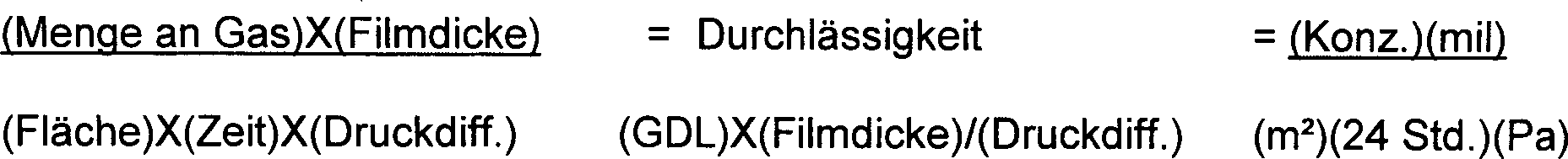
eine geeignete Methode zur Messung der relativen Permeanz, Durchlässigkeit
und Diffusion verschiedener Filmmaterialien ist im als ASTM 1434V
bezeichneten Verfahren wiedergegeben. Gemäß ASTM 1434V werden Permeanz,
Durchlässigkeit
und Diffusion mittels der folgenden Formeln gemessen: Permeanz ![]()
![]()
![]()
![]()
Unter Anlegung der oben dargestellten Formeln kann die Gasdurchlässigkeit in Kombination mit einem Konstantdruckdifferential und der Filmdicke zur Definition der Bewegung des Gases unter spezifischen Bedingungen angewendet werden. In dieser Hinsicht weist die bevorzugte Gasdurchlässigkeit (GDL) für eine Blase bei einer Sportschuh-Komponente, die den äußerst strengen Anforderungen an die Ermüdungsbeständigkeit, die für die starken und wiederholten Stöße erforderlich ist, genügen will, einen Wert von weniger als etwa 10, bevorzugter weniger als etwa 7,5, noch bevorzugter weniger als etwa 5, und sogar noch bevorzugter einen GDL-Wert von 2,0 oder weniger auf, wie vorzugsweise mittels der obigen Verfahrensweise gemessen.Under Application of the formulas set forth above may be gas permeability in combination with a constant pressure differential and the film thickness to define the movement of the gas under specific conditions be applied. In this regard, the preferred gas permeability (GDL) for a bubble in a sports shoe component, which is the most severe Requirements for fatigue resistance, the for the strong and repeated shocks required is enough , a value of less than about 10, more preferably less than about 7.5, more preferably less than about 5, and even more preferably a GDL value of 2.0 or less, preferably by means of measured by the above procedure.
Über das
zuvor genannte hinaus, sind in den
Das Hauptziel der vorliegenden Erfindung besteht in der Bereitstellung einer versiegelten Schlauchblase mit darin eingefangenem Gas zur Anwendung bei einer Abpolsterung, die eine mehrlagige Membran umfasst, welche (1) einen gewünschten Grad an Flexibilität (oder Steifigkeit) aufweist; (2) einen gewünschten Grad an Beständigkeit gegenüber einem durch Feuchtigkeit bewirkten Abbau aufweist, und (3) einen akzeptablen Grad an Undurchlässigkeit gegenüber Fluiden aufweist, die in Form von Gasen, Flüssigkeiten oder beidem vorliegen können, was hauptsächlich vom angestrebten Verwendungszweck des Produkts abhängt, wobei zugleich die Probleme nach dem Stand der Technik überwunden werden. Die Flexibilität und die Beständigkeit gegenüber einem durch Feuchtigkeit bewirkten Abbau werden durch Verwenden eines thermoplastischen Polyurethans erzielt, wohingegen die Undurchlässigkeit für Medien die Flüssigkeiten und/oder Gase durch Verwenden einer Zwischenschicht oder einer Schicht erreicht wird, die generell nicht der Atmosphäre des Barrierematerials ausgesetzt wird und die zum Beispiel ein Copolymer von Ethylen und Vinylalkohol umfasst.The The main object of the present invention is to provide a sealed tube bladder with trapped gas for Application in a padding comprising a multilayer membrane, which (1) a desired Degree of flexibility (or stiffness); (2) a desired degree of durability across from a degradation caused by moisture, and (3) a acceptable degree of impermeability across from Having fluids which are in the form of gases, liquids or both can, mainly depends on the intended use of the product, where at the same time overcome the problems of the prior art become. The flexibility and the resistance across from Moisture degradation is by using a thermoplastic polyurethane, whereas the impermeability for media the liquids and / or gases by using an intermediate layer or a layer which is generally not exposed to the atmosphere of the barrier material and, for example, a copolymer of ethylene and vinyl alcohol includes.
Dieses Ziel kann zum Beispiel durch Anwendung einer mehrlagigen Verarbeitungsweise erreicht werden, wie zum Beispiel dem Koextrusions-Blasformen oder der Koextrusion von Folien, Filmen, Schläuchen oder Profilen, wobei zum Beispiel ein separater Förderstromkanal für jedes Material vorgesehen ist. Typischerweise sind die ersten und zweiten Extrusionskanäle für das flexible Material (d. h. das thermoplastische Polyurethan) jeweils auf den beiden Seiten des Extrusionskanals für das Batteriematerial (d. h. das Copolymer von Ethylen und Vinylalkohol) angebracht.This Target can be achieved, for example, by applying a multi-layered processing method be achieved, such as coextrusion blow molding or the coextrusion of films, films, tubes or profiles, wherein For example, a separate flow channel for each Material is provided. Typically, the first and second extrusion channels for the flexible material (i.e., the thermoplastic polyurethane) respectively on the two sides of the extrusion channel for the battery material (i.e. H. the copolymer of ethylene and vinyl alcohol).
Die
Membran kann durch Laminieren des thermoplastischen Polyurethans
und des Hauptbarrierematerials hergestellt werden, indem die gewählten Materialien
bei einer Temperatur von etwa 149°C
bis 232°C (300°F bis 450°F) in Kontakt
gebracht werden. Die Laminierung innerhalb des Rahmens der vorliegenden
Erfindung kann mittels einer Vielfalt von Kunststoff-erzeugenden
Techniken durchgeführt
werden, um eine Bindung zwischen den beiden unterschiedlichen Materialien über praktisch die
gesamte vorgesehene Kontaktfläche
der beiden unterschiedlichen Materialien gemäß der folgenden Reaktion zu
erzielen, wenn ein Copolymer von Ethylen und Vinylalkohol zumindest
zum Teil als Barrierematerial eingesetzt wird; 
Gemäß einer ersten beispielhaften Ausführungsform besteht die Membran in einer Innenschicht aus dem Hauptbarrierematerial mit einer mittleren Dicke von etwa 10 Mikrometer bis etwa 500 Mikrometer, die zwischen eine erste Außenschicht und eine zweite Außenschicht bondiert ist, wobei beide Außenschichten aus einem Material hergestellt sind, das einen vorpolymeren thermoplastischen Polyurethanfilm einschließt oder daraus im wesentlichen besteht. Die ersten und zweiten Schichten des Laminats weisen typischerweise eine Dicke von mindestens 0,01 Millimeter (mm) für Anwendungen wie Hydraulikakkumulatoren auf. Es wird erwogen, Materialdicken von weniger als 0,01 mm für andere Anwendungen einzusetzen, wie zum Beispiel bei Filmen für die Lebensmittelverpackungsindustrie. Beim Laminierprozess der vorliegenden Erfindung wird die relative Position der Laminate kontrolliert, als auch (theoretisch) für die Oberflächenbindung zwischen den Laminaten gesorgt. Demgemäß sind Haftvermittler (oder Haftschichten, wie sie oftmals in der Thermoplast-erzeugenden Industrie genannt werden) nicht erforderlich oder erwünscht.According to a first exemplary embodiment, the membrane in an inner layer consists of the main barrier material having an average thickness of about 10 microns to about 500 microns, which is bonded between a first outer layer and a second outer layer, both outer layers are made of a material having a prepolymer thermoplastic polyurethane film includes or consists essentially thereof. The first and second layers of the laminate typically have a thickness of at least 0.01 millimeter (mm) for applications such as hydraulic accumulators. It is considered to use material thicknesses of less than 0.01 mm for other applications, such as Fil for the food packaging industry. The lamination process of the present invention controls the relative position of the laminates as well as (theoretically) provides surface bonding between the laminates. Accordingly, primers (or subbing layers, as they are often called in the thermoplastic industry) are not required or desired.
Gemäß einer zweiten beispielhaften Ausführungsform besteht die Membran aus einer Innenschicht, welche ein Hauptbarrierematerial mit einer Dicke von etwa 10 Mikrometern bis etwa 500 Mikrometern umfasst, die gemäß der oben angegebenen Reaktion an einer Seite an mindestens eine Außenschicht des thermoplastischen Polyurethans oberflächengebunden ist. Auch hier schafft der aus dem Laminierprozess der vorliegenden Erfindung resultierende Kontakt eine starke Oberflächenbindung zwischen den Schichten, was klebende Haftschichten unnötig macht. Gemäß noch weiterer beispielhafter Ausführungsformen werden Membranen beschrieben, die aus multiplen Schichten (d. h. mindestens fünf) einschließlich abwechselnder Schichten aus thermoplastischen Urethanen und Hauptbarrierematerialien, bestehen.According to one second exemplary embodiment the membrane consists of an inner layer, which is a main barrier material with a thickness of about 10 microns to about 500 microns includes, according to the above specified reaction on one side to at least one outer layer the thermoplastic polyurethane is surface-bound. Here too This results from the lamination process of the present invention Contact a strong surface bond between layers, which makes adhesive layers unnecessary. According to still further exemplary embodiments describes membranes consisting of multiple layers (i.e. at least five) including alternating layers of thermoplastic urethanes and main barrier materials, consist.
Noch weitere Vorteile und Aufgaben der vorliegenden Erfindung werden den Fachleuten des Gebiets aus der nachfolgenden ausführlichen Beschreibung, den Ansprüchen im Anhang und den Zeichnungen ersichtlich werden.Yet Further advantages and objects of the present invention to specialists of area from the following detailed Description, the claims in the appendix and the drawings.
Die vorliegende Erfindung betrifft auch die Verfahren und Methoden zur Herstellung der laminierten elastischen Barreriemembranen und ihre Formung zu einer Blase, ebenso wie die Blasen, die aus den derart hergestellten Membranen bestehen.The The present invention also relates to the methods and methods of Production of the laminated elastic Barreriemembranen and their Forming into a bubble, as well as the bubbles made from the thus prepared Consist of membranes.
Eine wichtige Anwendung der Ausführungsformen der vorliegenden Erfindung besteht in der Bereitstellung eines aufblasbaren Abpolsterungselements, das praktisch permanent mit Stickstoff oder einem anderen umweltfreundlichen Gas oder einer Kombination von Gasen aufgeblasen ist und das die Ziele von Flexibilität, Haltbarkeit und Kostengünstigkeit erfüllt.A important application of the embodiments The present invention is to provide an inflatable Upholstery element that is virtually permanent with nitrogen or another environmentally friendly gas or a combination of Gases is inflated and that the goals of flexibility, durability and cost-effectiveness Fulfills.
Ein weiteres Ziel dieser Ausführungsformen besteht in der Bereitstellung eines Abpolsterungselements mit einem durchlässigen Barrierematerial, welches einen Gasdurchlässigkeitswert von 10 oder weniger erreicht.One another objective of these embodiments consists in the provision of a padding element with a permeable Barrier material that achieves a gas transmission value of 10 or less.
Noch ein weiteres Ziel dieser Ausführungsformen besteht in der Bereitstellung eines Abpolsterungselements, welches im wesentlichen einem Abschälen zwischen den Schichten standhält, relativ transparent und in der Herstellung wirtschaftlich ist.Yet another objective of these embodiments It consists in the provision of a padding element, which essentially a peeling between the layers, relatively transparent and economical to manufacture.
Noch ein anderes Ziel dieser Ausführungsformen besteht in der Bereitstellung eines Abpolsterungselements, bei dem die Barriereschicht im wesentlichen einer Delaminierung standhalten kann und keine Haftschicht zwischen der Barriereschicht und den flexiblen Schichten benötigt.Yet another objective of these embodiments It consists in the provision of a padding element in which the barrier layer substantially withstand delamination can and no adhesive layer between the barrier layer and the flexible layers needed.
Wiederum ein anderes Ziel dieser Ausführungsformen besteht in der Bereitstellung eines Abpolsterungselements, welches unter Anwendung verschiedener Techniken herstellbar ist, einschließlich, ohne darauf beschränkt zu sein, der Blasformung, der Schlauch- und Folienextrusion, der Vakuumformung, der Heißsiegelung und des RF-Schweißens.In turn another objective of these embodiments It consists in the provision of a padding element, which can be prepared using various techniques, including, without limited to this to be, the blow molding, the tube and film extrusion, the Vacuum forming, heat sealing and RF welding.
Ein zusätzliches Ziel dieser Ausführungsformen besteht in der Bereitstellung eines Abpolsterungselements, welches das Entweichen von Gas entlang der Grenzflächen zwischen den Materialien über die Kapillarwirkung verhindert.One additional Goal of these embodiments It consists in the provision of a padding element, which the escape of gas along the interfaces between the materials over the Capillary action prevented.
Noch ein Ziel dieser Ausführungsformen besteht in der Bereitstellung eines Abpolsterungselements, welches eine normale Verarbeitung zu Schuhwerk zulässt, so zum Beispiel das Einbetten des Abpolsterungselements in ein formbares Material.Yet an objective of these embodiments It consists in the provision of a padding element, which normal processing to footwear, such as embedding the padding element into a moldable material.
Die obige Liste erhebt keinen Anspruch auf Vollständigkeit bezüglich der Aufgaben oder Vorteile der vorliegenden Erfindung.The The above list does not claim to be complete regarding the Objects or advantages of the present invention.
Mit diesen Ausführungsformen der vorliegenden Erfindung wird daher ein Abpolsterungselement bereitgestellt, welches ein oder mehrere neuartige gasbefüllte Membranen sowohl mit den gewünschten physikalischen Eigenschaften des thermoplastischen elastomeren Films als auch verbesserte Barriereeigenschaften zur Rückhaltung von Stickstoffgas oder anderen eingefangenen Gasen aufweist. Die gasbefüllten Membranen sind so formuliert, dass sie die Rate des Ausdiffundierens bestimmter eingefangener Gase (zum Beispiel Stickstoff oder Supergase) Gase durch die Membranen selektiv kontrollieren, als auch das Diffusionspumpen der mobilen Gase in der Außenumgebung (zum Beispiel Argon, Sauerstoff, Kohlendioxid und andere Gase, die in der Umgebungsluft vorhanden sind) in die gasbefüllten Membranen ermöglichen.With these embodiments of the present invention, therefore, there is provided a cushioning member having one or more novel gas-filled membranes having both the desired physical properties of the thermoplastic elastomeric film and improved barrier properties for retaining nitrogen gas or other trapped gases. The gas-filled membranes are formulated to control the rate of out-diffusion of certain trapped gases (e.g. Nitrogen or super gases) selectively control gases through the membranes, as well as allowing the diffusion of mobile gases in the external environment (e.g., argon, oxygen, carbon dioxide, and other gases present in the ambient air) into the gas-filled membranes.
Die gasbefüllten Membranen sind vorzugsweise aus mindestens zwei flexiblen Materialien konstruiert, die gemeinsam als eine Barriere dienen, und die vorzugsweise von elastomerer und polarer Natur sind und zu Produkten in vielfältigen Gestaltungen formbar sind.The gas filled Membranes are preferably made of at least two flexible materials designed to act together as a barrier, and preferably of elastomeric and polar nature and to products in diverse designs are malleable.
Idealerweise sollten die gemäß den Lehren der vorliegenden Erfindung verwendeten flexiblen Barrierematerialien das eingefangene Gas innerhalb eines Innenabteils der gasbefüllten Membran über einen relativ langen Zeitraum hinweg enthalten. Bei einer in hohem Maße bevorzugten Ausführungsform sollte die gasbefüllte Membran zum Beispiel nicht mehr als etwa 20% des wie anfangs aufgeblasenen Gasdrucks über einen Zeitraum von zwei Jahren hinweg verlieren. In anderen Worten sollten die ausgangs zu einem Konstantdruck von 137,9 bis 151,7 kPa (20,0 bis 22,0 psi) aufgeblasenen Produkte nach einem Zeitraum von etwa zwei Jahren einen Druck im Bereich von etwa 16,0 bis 18,0 psi beibehalten haben.Ideally should the according to the teachings flexible barrier materials used in the present invention the trapped gas within an inner compartment of the gas-filled membrane via a contained relatively long period of time. In a highly preferred embodiment should be the gas filled Membrane, for example, not more than about 20% of the initially inflated Gas pressure over lose a period of two years. In other words The output should be at a constant pressure of 137.9 to 151.7 kPa (20.0 to 22.0 psi) inflated products after a period of time from about two years, a pressure in the range of about 16.0 to 18.0 have maintained psi.
Außerdem sollten die verwendeten Barrierematerialien flexibel, relativ welch und nachgiebig sein und in hohem Maße ermüdungsbeständig und zum Erhalt wirksamer Siegelungen, wie sie typischerweise mittels RF-Schweißung oder Heißsiegelung erzielt werden, schweißbar sein. Das Barrierematerial sollte außerdem dazu in der Lage sein, hohen Zyklusbelastungen ohne Versagen standzuhalten, und besonders dann, wenn das verwendete Barrierematerial eine Dicke von etwa 5 mils bis etwa 50 mils aufweist. Eine weitere wichtige Eigenschaft der Membranen der vorliegenden Erfindung besteht darin, dass sie mittels der in der hochvolumigen Produktion angewandten Techniken zu verschiedenen Formen verarbeitbar sein sollten. Zu diesen erwünschten und im Fachgebiet bekannten Techniken zählen das Blasformen, das Spritzformen, das Vakuumformen, das Rotationsformen, das Spritzpressen und das Druckformen. Die Membranen der vorliegenden Erfindung sollten vorzugsweise mittels Extrusionsmethoden herstellbar sein, wie etwa der Schlauch- oder Folienextrusion, einschließlich dem Extrusions-Blasformen, und insbesondere bei ausreichend hohen Temperaturen, um die erwünschte ”haftende” oder ”chemische” Bindung zu erreichen, die nachstehend in größerer Ausführlichkeit beschrieben werden wird, ohne dass eine separate Klebe- oder Haftschicht verwenden zu müssen. Diese zuvor genannten Prozesse sollten Produkte ergeben, deren Querschnittsdimensionen variierbar sind.In addition, should the barrier materials used are flexible, relatively and be forgiving and to a great extent fatigue resistant and to obtain effective seals, typically by RF welding or Heat sealing be achieved, weldable be. The barrier material should also be able to high cycle loads without failure, and especially when the barrier material used has a thickness of about 5 mils to about 50 mils. Another important property The membrane of the present invention is that by means of the techniques used in high-volume production should be processable to various forms. To these desired and techniques known in the art include blow molding, injection molding, vacuum forming, rotational molding, transfer molding and the Printing forms. The membranes of the present invention should preferably be produced by extrusion methods, such as the hose or film extrusion, including the extrusion blow molding, and in particular at sufficiently high Temperatures to the desired "adhesive" or "chemical" bond which will be described in more detail below without using a separate adhesive or adhesive layer to have to. These The aforementioned processes should produce products whose cross-sectional dimensions are variable.
Wie oben erwähnt, besteht ein signifikantes Merkmal der Membranen der vorliegenden Erfindung in der kontrollierten Diffusion der mobilen Gase durch die Barriereschicht und der Zurückhaltung der darin eingefangenen Gase. Mittels der vorliegenden Erfindung sind nicht nur die supraflüssigen Gase als Einfanggase nutzbar, sondern kann auch Stickstoffgas aufgrund der verbesserten Leistung der Barriere als ein Einfanggas verwendet werden. Beim primären mobilen Gas handelt es sich um Sauerstoff, welcher relativ schnell durch die Barriere diffundiert, während die anderen mobilen Gase eines des normalerweise in Luft vorhandenen Gases mit Ausnahme von Stickstoff sein kann. Der praktische Nutzen der Bereitstellung eines Barrierematerials, bei dem sich Stickstoffgas als Einfanggas eignet, ist signifikant.As mentioned above, there is a significant feature of the membranes of the present invention Invention in the controlled diffusion of mobile gases the barrier layer and the restraint the gases trapped therein. By means of the present invention are not just the superfluous ones Gases can be used as capture gases, but can also nitrogen gas due the improved performance of the barrier used as a capture gas become. When primary Mobile gas is oxygen, which is relatively fast diffused through the barrier while the other mobile gases one of the gas normally present in air with the exception of Nitrogen can be. The practical benefits of providing a Barrier material in which nitrogen gas is suitable as a capture gas, is significant.
Zum Beispiel kann die Membran anfänglich mit Stickstoffgas oder einem Gemisch aus Stickstoffgas und einem oder mehreren der supraflüssigen Gase oder mit Luft aufgeblasen werden. Wenn mit Stickstoff oder einem Gemisch aus Stickstoff und einem oder mehreren supraflüssigen Gasen befüllt, so erfolgt ein Druckanstieg aus der relativ schnellen Diffusion von Sauerstoffgas in die Membran, da das eingefangene Gas im wesentlichen innerhalb der Membran zurückgehalten wird. Dies ergibt effektiv einen Druckanstieg von nicht mehr als etwa 17,2 kPa (2,5 psi) gegenüber dem Ausgangs-Aufblasdruck und führt so zu einem relativ mäßigen Volumenzuwachs der Membran von zwischen 1 und 5% in Abhängigkeit vom Ausgangsdruck. Wird allerdings Luft als Aufblasgas verwendet, so zeigt der Sauerstoff eine Neigung zum Ausdiffundieren aus der Membran, während der Stickstoff als eingefangenes Gas zurückbleibt. In diesem Fall führt die Diffusion des Sauerstoffs aus der Membran heraus und die Zurückhaltung des eingefangenen Gases zu einem zusätzlichen Abfall des Konstantdrucks gegenüber dem Ausgangs-Aufblasdruck.To the For example, the membrane may be initially with nitrogen gas or a mixture of nitrogen gas and a or more of the superfluid ones Gases or be inflated with air. If with nitrogen or a Mixture of nitrogen and one or more superfluid gases filled, Thus, a pressure increase takes place from the relatively fast diffusion of oxygen gas into the membrane, since the trapped gas is substantially retained within the membrane becomes. This effectively results in a pressure increase of not more than about 17.2 kPa (2.5 psi) the initial inflation pressure and leads so to a relatively moderate increase in volume the membrane of between 1 and 5% depending on the outlet pressure. However, if air is used as the inflation gas, then the oxygen shows a tendency to diffuse out of the membrane during the Nitrogen remains as trapped gas. In this case, the leads Diffusion of oxygen out of the membrane and restraint of the trapped gas to an additional drop in constant pressure across from the initial inflation pressure.
Die Merkmale und Vorteile der vorliegenden Erfindung werden beim Überdenken der folgenden Beschreibung von beispielhaften Ausführungsformen in Verbindung mit den begleitenden Zeichnungen ersichtlicher werden, wobei:The Features and advantages of the present invention will be under consideration the following description of exemplary embodiments become more apparent in connection with the accompanying drawings, in which:
Im
folgenden wird Bezug genommen auf die Zeichnungen, worin entsprechende
Bezugsnummern gleiche oder entsprechende Teile in den verschiedenen
Ansichten bezeichnen, wobei in
Bei dem gemäß den Lehren der vorliegenden Erfindung verwendeten thermoplastischen Urethan handelt es sich allgemein um kommerziell verfügbare Produkte wie PellethanTM (ein Markenprodukt von Dow Chemical Co. of Midland, MI) und Elastollan® (eingetragenes Warenzeichen der BASF Corporation) und Estane® (eingetragenes Warenzeichen der B.F. Goodrich Co.), bei denen es sich in allen Fällen um Urethane entweder auf Ester- oder Ether-Basis handelt, die so ausgeführt sind, dass sie den damit hergestellten Produkten flexible Eigenschaften zu verleihen.The used in accordance with the teachings of the present invention, thermoplastic urethane is generally to commercially available products such as Pellethane ™ (a trademark product of Dow Chemical Co. of Midland, MI) and Elastollan ® (registered trademark of the BASF Corporation) and Estane ® (registered Trademark of BF Goodrich Co.), which in all cases are either ester or ether based urethanes, designed to impart flexible properties to the products made therewith.
Über diese kommerziell verfügbaren thermoplastischen Urethane hinaus können weitere Materialien verwendet werden, gewählt aus der Gruppe, bestehend aus Polyestern, Polyethern, Polycaprolactonen, Polyoxypropylenen und Polycarbonaten, und Gemischen davon.About these commercially available thermoplastic urethanes can be used in addition to other materials are elected from the group consisting of polyesters, polyethers, polycaprolactones, Polyoxypropylenes and polycarbonates, and mixtures thereof.
Die gemäß den Lehren der vorliegenden Erfindung verwendeten Copolymere von Ethylen und Vinylalkohol sind ebenfalls vorzugsweise kommerziell verfügbare Produkte wie EVAL®, ein eingetragenes Warenzeichen der Eval Company of Elisle, Illinois, und SOARNOLTM (von Nippon Gosei Co., Ltd. (USA) of New York, N.Y. beziehbares Markenprodukt)., die beide auf eine relativ hohe Beständigkeit gegenüber einem Abbau durch Feuchtigkeit hin ausgeführt sind und hervorragende Barriereeigenschaften bezüglich einem unerwünschten Gasdurchtritt bieten.The copolymers used according to the teachings of the present invention of ethylene and vinyl alcohol are also preferably products commercially available as EVAL ®, a registered trademark of Eval Company of Elisle, Illinois, and SOARNOL ™ (available from Nippon Gosei Co., Ltd. (USA) of New York, NY), both of which exhibit relatively high resistance to degradation by moisture and offer excellent barrier properties to undesirable gas leakage.
Wichtig ist, zur Kenntnis zu nehmen, dass eine Vielzahl von Produkten hergestellt werden kann, die die hierin beschriebenen Blasen enthalten oder verwenden, einschließlich, ohne Einschränkung, von Blasen, die für aufblasbare Objekte nützlich sind, wie z. B. Fußbälle, Basketbälle, Sockerbälle und Innenschläuche, Schuhwerk; Lebensmittelverpackungsfilme, Treibstoffleitungen, Treibstoff-Lagertanks; und Druckspeicher, und weiteres.It is important to note that a variety of products can be made that contain or use the bladders described herein, including, without limitation, bladders useful for inflatable objects, such as bladders. Footballs, basketballs, sockets and inner tubes, footwear; Food packaging films, fuel lines, fuel storage tanks; and accumulators, and more.
In
Wie nachstehend in größerer Ausführlichkeit erläutert werden wird, soll der hierin verwendete Begriff ”laminiert” den Kontakt in Form einer primären Wasserstoffbindung bedeuten, die zwischen den jeweiligen Schichten entlang ausgedehnter Längen des Produkts auftritt. Die Ausführungsformen der Membranen der vorliegenden Erfindung sind nicht nur mehrlagig, sondern auch beständig gegenüber einer Delaminierung, die oftmals bei unter harten Umweltbedingungen verwendeten Produkten auftritt.As below in greater detail explained As used herein, the term "laminated" as used herein is intended to mean contact primary Mean hydrogen bonding between the respective layers along extended lengths of the product occurs. The embodiments The membranes of the present invention are not only multi-layered, but also constantly across from delamination, often in harsh environments used products occurs.
Wichtig
ist, zur Kenntnis zu nehmen, dass die Membran
Außerdem kann
die erste Schicht
In
In
Beispielsweise
ist in
Als
weiteres Beispiel ist in
Vorzugsweise sind das thermoplastische Polyurethan und der Ethylen-Vinylalkohol nicht bei dem Versuch modifiziert worden, eine Vernetzung oder herkömmliche kovalente Bindung zwischen den beiden Schichten zu schaffen, noch werden irgendwelche Haftschichten oder Haftvermittler verwendet. Die bevorzugten Zusammensetzungen und Methoden der vorliegenden Erfindung vertrauen ausschließlich auf die dem thermoplastischen Urethan und dem Copolymer von Ethylen und Vinylalkohol zueigenen Eigenschaften, die sich zeigen, wenn diese gemäß den Methoden der vorliegenden Erfindung in Kontakt gebracht werden, wodurch zum Beispiel die zwischen den jeweiligen Schichten auftretende Wasserstoffbrückenbindung maximiert wird und so die Bindung primär darauf basiert.Preferably are the thermoplastic polyurethane and the ethylene-vinyl alcohol not modified in the experiment, a crosslinking or conventional to create covalent bond between the two layers, still Any adhesive layers or adhesion promoters are used. The preferred compositions and methods of the present invention Invention trust exclusively on the thermoplastic urethane and the copolymer of ethylene and vinyl alcohol inherent properties that show up when these according to the methods be brought into contact with the present invention, whereby, for example the hydrogen bonding occurring between the respective layers is maximized and so the bond is primarily based on it.
Um die Membranen 10 gemäß den Lehren der vorliegenden Erfindung herzustellen, kann eine Anzahl unterschiedlicher Verfahren angewandt werden, einschließlich, doch nicht beschränkt auf das Koextrusionsblasformen unter Anwendung des Endlosstrangpressens, die intermittierende Extrusion unter Anwendung von (1) Schneckenspritzgießsystemen; (2) Druckakkumulator-artigen Systemen; (3) und Akkumulator-Kopfsystemen, das Koinjektions-Streckblasen oder der Verwendung von koextrudierten Folien, blasgeformten Filmen, Schläuchen oder Profilen. Es wurde festgestellt, dass Mehrschichtprozesse wie die Schlauch-, Folien- und Filmextrusion, als auch das Blasformen unter Anwendung von Koextrusionen Produkte ergeben, die die gewünschte signifikante Wasserstoffbrückenbindung zwischen den jeweiligen Schichten aus thermoplastischem Urethan und den Copolymeren von Ethylen und Vinylalkohol zu zeigen scheinen. Um zum Beispiel ein Produkt wie eine Hydraulikakkumulator-Blase oder ein Diaphragma über einen Mehrschichtprozess wie der Blasformung zu erhalten, würde ein Produkt gemäß den Lehren der vorliegenden Erfindung typischerweise wie folgt unter Anwendung einer von vielen kommerziell verfügbaren Blasformmaschinen bearbeitet werden, wie z. B. einem Bekum BM502 unter Verwendung eines Koextrusionskopf-Modells Nr. BKB95-3B1 (nicht gezeigt) oder einem Krup KEB-5 unter Verwendung eines Modell Nr. VW60/35-Koextrusionskopfes (nicht gezeigt).Around the membranes 10 according to the teachings of the present invention may be a number of different Methods are used, including but not limited to coextrusion blow molding using continuous extrusion, intermittent extrusion using (1) screw injection molding systems; (2) pressure accumulator-like systems; (3) and accumulator head systems, co-injection stretch blow molding or the use of coextruded Films, blow-molded films, hoses or profiles. It was found that multi-layer processes such as tube, film and and film extrusion, as well as blow molding using coextrusions Products that give the desired significant hydrogen bonding between the respective layers of thermoplastic urethane and the copolymers of ethylene and vinyl alcohol. For example, a product such as a hydraulic accumulator bladder or a diaphragm over To obtain a multi-layer process such as blow molding would be Product according to the teachings The present invention is typically practiced as follows one of many commercially available blow molding machines processed be such. A Bekum BM502 using a coextrusion head model No. BKB95-3B1 (not shown) or a Krup KEB-5 using a Model No. VW60 / 35 coextrusion head (not shown).
Zunächst werden die harzartigen Materialien (nämlich die thermoplastischen Urethane und das Barrierematerial, zum Beispiel die Copolymere von Ethylen und Vinylalkohol) gemäß der Anleitung des Herstellers getrocknet (sofern erforderlich) und in den Extruder eingespeist. Typischerweise werden die Materialien in die Extruder entsprechend der Reihenfolge, in der die Schichten angeordnet werden sollen, eingespeist, zum Beispiel TPU in einen äußeren Extruder, EVOH in einen mittleren Extruder und TPU in den Innenextruder. Das Erhitzungsprofil des Extruders wird gemäß dem besten Verarbeitungsmodus für die einzelnen Materialien eingestellt. Allerdings wird vorgeschlagen, dass nicht mehr als 11°C (20°F) Differenz am Ausgang jedes Extruders vorliegen sollte. Während des Vorantreibens des Materials in jedem Extruder wird das Erhitzungsprofil so eingestellt, dass die beste Massenschmelze erreicht wird. Das Erhitzungsprofil wird typischerweise auf zwischen 149°C und 232°C (300°F bis etwa 450°F) eingestellt, wobei die Beschickungszone der niedrigste Sollwert ist und alle anderen Sollwerte in Schritten von etwa 55°C (100°F) graduell angehoben werden, bis die gewünschte Schmelze erreicht ist. Hat diese die Extruder verlassen, so dient manchmal ein Rohr- oder Kanalabschnitt dazu, das Material zum Mehrschichten-Kopf (d. h. drei oder mehr Köpfe) zu dirigieren. Zu diesem Zeitpunkt werden die Einstellungen für die Wärmedifferenzen vorgenommen. Die Pumpwirkung der Extruder drängt das Material nicht nur in die einzelnen Kopfkanäle oder Fließwege, sondern bestimmt auch die Dicke jeder Schicht. Beispielsweise weist dann, wenn der erste Extruder einen Durchmesser von 60 mm besitzt, der zweite Extruder einen Durchmesser von 35 mm und der dritte Extruder ebenfalls einen solchen von 35 mm auf, beträgt die erforderliche Geschwindigkeit, um eine 1,3 Liter-Blase oder Diaphragma, bestehend aus 2 mm für die Außenschicht aus TPU, 3 mils für die EVOH-Schicht und 2 mm für die Innenschicht aus TPU bei einer erwünschten Zyklusdauer von 26 Sekunden zu erzeugen, für den ersten Extruder eine Schneckendrehzahl von etwa 10 UpM, für den zweiten Extruder eine Schneckendrehzahl von etwa 5 UpM und für den dritten Extruder eine Schneckendrehzahl von etwa 30 UpM. Ist das Material einmal in die Kopfkanäle oder Fließwege eingetreten, so wird die Wärme normalerweise konstant gehalten oder zur Einstellung der Schmelzenzähigkeit der Materialien gesenkt. Die einzelnen Kopfkanäle oder Fließwege halten die geschmolzenen Massen voneinander getrennt, während sie sie abwärts und in die Form eines Vorformlings dirigieren.First, the resinous materials (namely, the thermoplastic urethanes and the barrier material, for example the copolymers of ethylene and vinyl alcohol) are dried (if necessary) according to the manufacturer's instructions and fed into the extruder. Typically, the materials are fed into the extruders according to the order in which the layers are to be placed, for example TPU in an outer extruder, EVOH in a middle extruder, and TPU in the inner extruder. The heating profile of the extruder is set according to the best processing mode for the individual materials. However, it is suggested that there should be no more than 11 ° C (20 ° F) difference at the exit of each extruder. As the material in each extruder advances, the heating profile is adjusted to achieve the best mass melt. The heating profile is typically set at between 149 ° C and 232 ° C (300 ° F to about 450 ° F) with the feed zone being the lowest set point and gradually raising all other set points in steps of about 55 ° C (100 ° F) until the desired melt is reached. When this leaves the extruders, sometimes a tube or channel section serves to direct the material to the multilayer head (ie, three or more heads). At this time The settings for the heat differences are made. The pumping action of the extruder not only forces the material into the individual head channels or flow paths, but also determines the thickness of each layer. For example, if the first extruder has a diameter of 60 mm, the second extruder has a diameter of 35 mm and the third extruder also has a diameter of 35 mm, the required speed is around a 1.3 liter bladder or diaphragm consisting of 2 mm for the outer layer of TPU, 3 mils for the EVOH layer and 2 mm for the inner layer of TPU to produce at a desired cycle time of 26 seconds, for the first extruder a screw speed of about 10 rpm, for the second Extruder screw speed of about 5 rpm and for the third extruder a screw speed of about 30 rpm. Once the material has entered the head channels or flow paths, the heat is usually held constant or lowered to adjust the melt tenacity of the materials. The individual head channels or flow paths keep the molten masses separated while directing them down and into the shape of a preform.
Direkt vor Eintritt in die untere Düse oder Buchse und den unteren Dorn werden die Materialkanäle oder Fließwege unter dem Druck zusammengeführt, der durch den Oberflächenbereich der jetzt vereinigten Fließwege, dem Leerraum zwischen der unteren Buchse und dem Dorn und dem Druck der einzelnen Schichten aus den jeweiligen Extrudern erzeugt wird. Dieser Druck muss mindestens 1379 kPa (200 psi) betragen und liegt normalerweise unter den beschriebenen Bedingungen bei über 5516 kPa (600 psi). Zu dem Zeitpunkt, zu dem die Materialien zusammenkommen, wird nun ein Vorformling gebildet, bei welchem es sich um ein aus drei Schichten, nämlich thermoplastisches Urethan, Copolymer von Ethylen und Vinylalkohol und thermoplastisches Urethan, bestehendes Laminat handelt, die wie hierin beschrieben miteinander bondiert werden. Die Obergrenze für den Druck wird im wesentlichen lediglich durch die physikalische Stärke des Kopfes beschränkt. Nach Anregen des Kopfes wird das Laminat an jedem Ende durch die beiden Formhälften verschlossen und ein Gas, wie z. B. Luft, in die Form injiziert, was den Laminatvorformling zum Aufblasen gegen die Form und Verbleiben in dieser Weise zwingt, bis eine ausreichende Abkühlung erfolgt ist (d. h. etwa 16 Sekunden für die zuvor genannte Probe), zu welchem Zeitpunkt das Gas abgelassen wird. Das Teil wird dann aus der Form entnommen und ausreichend lange einer weiteren Kühlung unterzogen, um eine weitere Entgasung des Teils oder weitere Verarbeitung zu ermöglichen, wie eventuell bei einigen Teilen erforderlich. Wie für Fachleute des Gebiets jetzt klar sein sollte, müssen die Schichten bis zur vollständigen Schmelze separat gehalten werden und in einem Hohlrohr vorgeformt werden, zu welchem Zeitpunkt sie bei hierin beschriebener Hitze und Druck gebunden werden.Directly before entering the lower nozzle or bushing and the lower mandrel become the material channels or flow paths merged under pressure, through the surface area the now united flow ways, the void between the lower bushing and the mandrel and the pressure the individual layers is produced from the respective extruders. This pressure must be at least 1379 kPa (200 psi) and is normally under the conditions described above 5516 kPa (600 psi). By the time the materials come together, Now a preform is formed, which is one of three Layers, namely thermoplastic urethane, copolymer of ethylene and vinyl alcohol and thermoplastic urethane, existing laminate is the bonded together as described herein. The upper limit for the Pressure is essentially only due to the physical strength of the Head restricted. After stimulation of the head, the laminate at each end through the two mold halves closed and a gas, such as. Air, injected into the mold, what the laminate preform to inflate against the mold and stay forces in this way until sufficient cooling takes place is (i.e., about 16 seconds for the aforementioned sample), at which time the gas is drained becomes. The part is then removed from the mold and sufficient long for another cooling subjected to further degassing of the part or further processing to enable as may be required for some parts. As for professionals of the area should now be clear, the layers have to be up to complete Melt be kept separately and preformed in a hollow tube at what time they are at the heat and heat described herein To be bound by pressure.
Wie die Fachleute der Kunststoff-erzeugenden Industrie erkennen werden, liegen die drei Hauptkomponenten einer Blasformmaschine, nämlich die Extruder, die Düsenköpfe und die Formklammern, in einer Anzahl unterschiedlicher Größen und Anordnungen vor, um dem Produktionsratenschema und den Größenanforderungen gerecht zu werden.As the professionals of the plastic-producing industry will realize are the three main components of a blow molding machine, namely the Extruder, the nozzle heads and the form clamps, in a number of different sizes and Arrangements prior to the production rate scheme and size requirements to meet.
Ein als Folienkoextrusion bekannter Mehrschichtprozess bezieht eine Extrusionstechnik ein, bei der gleichzeitig zwei oder mehrere Polymere durch eine einzige Düse extrudiert werden, wobei die Polymere so zusammengebracht werden, dass sie unterschiedliche, gut bondierte Schichten in Form eines einzigen Extrusionsprodukts ergeben. Typische Schichtstrukturen sind wie folgt definiert:One a film coextrusion known multilayer process refers to a Extrusion technology, in which two or more polymers simultaneously through a single nozzle be extruded, the polymers are brought together so that they have different, well-bonded layers in the form of a single extrusion product. Typical layer structures are defined as follows:
A-BFROM
Zwei verschiedene Schichten, bestehend aus zwei Harzen.Two different layers, consisting of two resins.
A-B-AA-B-A
Drei verschiedene Schichten, bestehend aus zwei oder drei Harzen.Three different layers, consisting of two or three resins.
A-B-A-B-AA-B-A-B-A
Fünf verschiedene Schichten, bestehend aus zwei, drei, vier oder fünf Harzen.Five different Layers consisting of two, three, four or five resins.
A-B-AA-B-A
Bei Erzeugung eines dreilagigen Folienkoextrusionsprodukts besteht A-B-A aus zwei Harzen. (A-Schicht = TPU, B-Schicht = EVOH).at Production of a three-layer film coextrusion product is A-B-A from two resins. (A-layer = TPU, B-layer = EVOH).
Die
technische Ausstattung zur Herstellung der koextrudierten Folie
besteht aus jeweils einem Extruder für jede Art von Harz, die dann
zu einem Koextrusions-Beschickungsblock
in der in
Die
zur Herstellung koextrudierter Schläuche erforderliche technische
Ausstattung besteht in jeweils einem Extruder für jede Art von Harz. Diese
Extruder werden an eine gemeinsame Verteilerrohrdüse angeschlossen.
Die Polymerschmelze aus jedem Extruder tritt in einen Düsenverteiler
ein, wie zum Beispiel in
Unabhängig vom angewandten Kunststoff-erzeugenden Prozess ist es von äußerster Wichtigkeit, dass eine gleichbleibende Schmelze des harzartigen thermoplatischen Urethans und Ethylen-Vinylalkohols zur Erzielung der gewünschten umfangreichen Wasserstoffbrückenbindung zwischen beiden entlang der vorgesehenen Länge oder des Segments des laminierten Produkts erhalten wird. Daher sollten die angewandten Mehrschichtprozesse bei Konstanttemperaturen von etwa 300°F bis etwa 450°F für die thermoplastischen Urethane und das Ethylen-Vinylalkohol-Copolymer durchgeführt werden. Weiterhin ist wichtig, einen ausreichenden Druck von mindestens 200 psi zu dem Zeitpunkt aufrechtzuerhalten, zu dem die Wasserstoffbrückenbindung eintritt, um eine umfassende Wasserstoffbrückenbindung zu erhalten.Independent of applied plastic-producing process is of utmost importance Importance that a consistent melt of the resinous thermoplastic urethane and ethylene-vinyl alcohol to achieve the desired extensive hydrogen bonding between the two along the intended length or the segment of the laminated Product is obtained. Therefore, the applied multilayer processes should at constant temperatures of about 300 ° F to about 450 ° F for the thermoplastic Urethanes and the ethylene-vinyl alcohol copolymer are performed. It is also important a sufficient pressure of at least 200 psi at the time to maintain the hydrogen bonding occurs to a comprehensive hydrogen bonding to obtain.
Theoretische BindungsreaktionTheoretical binding reaction
Bezugnehmend
insbesondere auf 
Es
wurden Tests an den Materialien durchgeführt, die zur Herstellung der
laminierten Membranen
Daraufhin
wurden Proben in Form von Dünnfilmen
zum Zwecke einer Charakterisierung der möglichen Oberflächenreaktion
zwischen den im thermoplastischen Urethan enthaltenen Sauerstoffmolekülen und
den durch die Vinylalkohol-Komponente
des Copolymers von Ethylen und Vinylalkohol bereitgestellten Hydroxylgruppen
präpariert.
Relativ dünne
Filme wurden aus Elastollan® C-90A-13(000) (thermoplastisches Urethan auf
Polyester-Basis), PellethaneTM 2355-87AE
(thermoplastisches Urethan auf Polyester-Basis) und SOARNOLTM (Ethylen-Vinylalkohol-Copolymer) hergestellt.
Zusätzlich
wurde ein Dünnfilm
aus einem dreilagigen Laminat erzeugt, umfassend eine erste Schicht
aus PellethaneTM 2355-80AE oder 2355-80AE, eine zweite Schicht
aus EVALTM und eine dritte Schicht aus PellethaneTM 2355-80AE. Gemäß dem in
Zusätzlich zur auftretenden theoretischen Wasserstoffbrückenbindung tragen auch weitere Faktoren wie Orientierungskräfte und Induktionskräfte, auch bekannt als vander-Waalssche-Kräfte, die aus zwischen zwei beliebigen Molekülen vorliegenden London-Kräften, und aus zwischen polaren Molekülen vorliegenden Dipol-Dipol-Kräften resultieren, zur Bindungsfestigkeit zwischen benachbarten Schichten des thermoplastischen Materials und des Hauptbarrierematerials bei.In addition to occur further theoretical hydrogen bonding Factors like orientation and induction forces, also known as Vander-Waalssche forces, dating back to between two any molecules present London forces, and out between polar molecules present dipole-dipole forces result, bond strength between adjacent layers of the thermoplastic Materials and the main barrier material.
Die
Wasserstoffbrückenbindung
zwischen den Schichten aus thermoplastischem Urethan und dem Ethylen-Vinylalkohol-Copolymer
der vorliegenden Erfindung steht in Kontrast zu Ausführungsformen
nach dem Stand der Technik, welche in Nichtanerkennung der Existenz
und/oder des Potentials solcher Bindungen typischerweise klebende
Haftschichten wie zum Beispiel Bynel verwendet haben, um die Bindung
zwischen den verschiedenen Schichten aus thermoplastischem Urethan
und Ethylen-Vinylalkohol zu verbessern und aufrechtzuerhalten. Das
Versäumnis
nach dem Stand der Technik, die Existenz und/oder das Potential
solch einer Bindung anzuerkennen, ist weiter verdeutlicht in
Es
sollte zur Kenntnis genommen werden, dass die zahlreichen möglichen
Produkte, die aus den hierin beschriebenen Membranen
In
Gemäß der vorliegenden
Erfindung enthält
die Sohlenstruktur
Zwar wurde bisher bereits eine Reihe schlauchförmiger Elemente und Fersenstücke in einer Form ähnlich den hierin beschriebenen kommerziell verwendet, doch wurden diese schlauchförmigen Elemente und Fersenstücke der bisherigen Ausführungsformen typischerweise aus einzelnen elastomeren Materialien hergestellt. Beispielsweise wurden die oftmals für Membranen (oder Hüllen, wie sie in den genannten Literaturstellen häufig bezeichnet werden) verwendeten Materialien typischerweise gewählt aus der Gruppe, bestehend aus Polyurethan- Elastomermaterialien, Polyesterelastomeren, Fluoroelastomeren, Polyvinylchloridelastomeren und ähnlichem, wobei die resultierenden Produkte mit ein oder mehreren Supergasen aufgeblasen wurden. Dabei waren die Polyurethan-Elastomermaterialien aufgrund ihrer hervorragenden Heißssiegel-Eigenschaften, Biegeermüdungsbeständigkeit, dem geeigneten Elastizitätsmodul, Zug- und Reißfestigkeit und Abriebsfestigkeit allgemein bevorzugt. Allerdings sind die im Fachgebiet beschriebenen Polyurethan-Elastomersysteme (d. h. die einzeln oder in Kombination mit kristallinen Materialien verwendet werden) eher wesentlich weniger wirksam als eine Barriere gegen die unerwünschte Diffusion von Gasen und Supergasen als die Membranen der vorliegenden Erfindung. Daher besteht ein Ziel der vorliegenden Erfindung in der Ausnutzung der durch Polyurethanelastomere im allgemeinen verfügbar gemachten Eigenschaften bei gleichzeitiger Steigerung dieser Eigenschaften durch Bereitstellung eines verbesserten Barrierematerials, das die Vorteile des Diffusionspumpens bietet, ohne dass auf einen Haftvermittler oder eine Haftschicht zurückgegriffen werden müsste, und welches bei einer breiten Vielfalt von im Fachgebiet beschriebenen Herstellungsprozessen angewandt werden kann.Though has already been a series of tubular elements and heel pieces in one Similar shape used commercially as described herein, but have become tubular Elements and heel pieces the previous embodiments typically made from individual elastomeric materials. For example, those often used for membranes (or sheaths, such as they are often referred to in the cited references) Materials typically chosen from the group consisting of polyurethane elastomeric materials, polyester elastomers, Fluoroelastomers, polyvinylchloride elastomers and the like, the resulting products having one or more super gases were inflated. The polyurethane elastomer materials were due to their excellent heat seal properties, Flexural fatigue resistance, the appropriate modulus of elasticity, Tensile and tear strength and abrasion resistance are generally preferred. However, the im In the field of polyurethane elastomer systems (i.e. used singly or in combination with crystalline materials be rather less effective as a barrier against the unwanted Diffusion of gases and super gases as the membranes of the present Invention. Therefore, an object of the present invention is in the utilization of the polyurethane elastomers generally made available Properties while increasing these properties by providing an improved barrier material that the Advantages of diffusion pumping without having to use a bonding agent or an adhesive layer used would have to and which are in a wide variety of ways described in the art Manufacturing processes can be applied.
Es
wird nochmals Bezug genommen auf
Die
Außenschicht
Zu
den zahlreichen thermoplastischen Urethanen, die zur Herstellung
der Außenschicht
Die
Innenschicht
Von
den oben aufgelisteten Materialien ist eine aus einem Copolymer
hergestellte Innenschicht
Das
Diffusionspumpen ist beschrieben in
Wie
in der
Nachdem der Druck einen Spitzenwert erreicht hat, ist die Rate der Abnahme sehr gering und bleibt der Gesamtdruck in der Membran etwa zwei Jahre oder länger über dem Ausgangsdruck, was vom speziell verwendeten Aufblasgas, dem Material, aus dem die Membran hergestellt ist und dem Aufblasdruck abhängt. Wie oben angemerkt, kann sich die Druckabnahme fortsetzen, doch angesichts der langsamen Diffusionsrate des Gases aus der Membran bleibt der Druck in der Membran ausreichend hoch, um eine wirksame weitere Nutzung der Membran über einige weitere Jahre hinweg zu ermöglichen. Die Membran ist daher praktisch permanent aufgeblasen.After this the pressure has peaked is the rate of decline very low and the total pressure in the membrane remains about two Years or longer over that Output pressure, what of the specially used inflation gas, the material, from which the membrane is made and the inflation pressure depends. As noted above, the pressure decrease may continue, but given the slow diffusion rate of the gas from the membrane remains Pressure in the membrane is high enough to be effective further use the membrane over for a few more years. The membrane is therefore practically permanently inflated.
Zu Zwecken des praktischen kommerziellen Nutzens der Produkte der vorliegenden Erfindung ist die Erzielung eines geeigneten und optimierten Gleichgewichts wichtig zwischen: (1) Einer Minimalrate an aktivierter Diffusion einerseits, und (2) solchen physikalischen Eigenschaften wie Ermüdungsbeständigkeit, Verarbeitbarkeit und Heißsiegelbarkeit andererseits. Daher bilden die Membranen vorzugsweise keine 100%-ige Barriere gegen eine Diffusion, sondern sind für Gase wie Sauerstoff durchlässig und verhindern zugleich wirksam den Durchtritt anderer Gase einschließlich Stickstoff und der Supergase durch die Membran.To For the practical commercial benefit of the products of the present Invention is the achievement of a suitable and optimized balance important between: (1) A minimum rate of activated diffusion on the one hand, and (2) such physical properties as fatigue resistance, Processability and heat sealability on the other hand. Therefore, the membranes preferably do not form a 100% barrier against diffusion, but are permeable to gases such as oxygen and at the same time effectively prevent the passage of other gases including nitrogen and the supergase through the membrane.
Die Tatsache, dass Sauerstoff durch die Membran diffundieren kann, stellt kein Problem dar, sondern ist tatsächlich ein wünschenswerter und einzigartiger Vorteil. Zum Beispiel kann nach Aufblasen der Membran mit Stickstoff und/oder Supergas der Sauerstoff aus der Umgebungsluft durch den Mechanismus des Diffusionspumpens in die Membran diffundieren, wie zuvor beschrieben. Folglich addiert sich der Partialdruck des Sauerstoffs auf die Partialdrücke des bereits in der Membran enthaltenen Stickstoffs und/oder Supergases auf, mit dem Ergebnis, dass der Gesamtdruck des Produkts steigt. Der Partialdruck des Sauerstoffs in der Umgebungsluft beträgt etwa 17,2 kPa (2,5 psi) (von einem Gesamtdruck bei Meeresspiegel von 101,4 kPa (14,7 psi)). Folglich bewirkt die Umkehrdiffusion des Sauerstoffgases in die Membran einen maximalen Druckanstieg von etwa 17,2 kPa (2,5 psi). Solch ein Druckanstieg ist zur Kompensierung der beträchtlichen Zugentspannung der Membran (bei resultierendem Anstieg des Innenvolumens der Umhüllung) nützlich, wodurch alle der Gaskomponenten der Luft in die Membran diffundieren. Daher besteht eines der Merkmale dieser Erfindung darin, dass das Verbundmaterial der Membran in einer halbdurchlässigen Membran für alle anderen Gase in der Luft als Stickstoff besteht und daher keine vollkommene Gasbarriere ist. Der praktische Vorteil ist der, dass der Druckverlust, der aufgrund des durch die Filmentspannung erzeugten Volumenanstiegs entsteht, trotzdem durch das Diffusionspumpen des Sauerstoffs ausgeschaltet ist.The fact that oxygen can diffuse through the membrane is not a problem but is actually a desirable and unique benefit. For example, after inflation of the membrane with nitrogen and / or super gas, the oxygen from the ambient air may diffuse into the membrane through the mechanism of diffusion pumping as previously described. Consequently, the partial pressure of the oxygen is added to the partial pressures of the nitrogen and / or super-gas already contained in the membrane, with the result that the total pressure of the product increases. The partial pressure of oxygen in the environment ambient air is about 17.2 kPa (2.5 psi) (from a total sea level pressure of 101.4 kPa (14.7 psi)). Thus, reverse diffusion of the oxygen gas into the membrane causes a maximum pressure increase of about 2.5 psi. Such a pressure increase is useful for compensating for the significant strain relief of the membrane (with a resultant increase in the interior volume of the enclosure) whereby all of the gas components of the air diffuse into the membrane. Therefore, one of the features of this invention is that the composite material of the membrane in a semipermeable membrane for all other gases in the air is nitrogen and therefore is not a perfect gas barrier. The practical advantage is that the pressure loss due to the increase in volume caused by the film tension is still eliminated by the diffusion pumping of the oxygen.
Einer der praktischen Vorteile durch die Kontrolle der Durchlässigkeit und das Diffusionspumpen betrifft das Anpassen der Zugentspannungs-Eigenschaften des Produkts den Druckveränderungen aufgrund der Rückhaltung des eingefangenen Gases und der Diffusion des mobilen Gases. Zum Beispiel ist bei einigen Produkten die Verwendung eines Films erwünscht, der entweder einen niedrigeren Elastizitätsmodul oder eine dünnere Dicke aufweist, damit sich das Abpolsterungselement weicher anfühlt. Bei geringerer Dicke oder Modul steigt die Neigung des eingefangenen Gases zum Diffundieren durch die Barriere. Um solch einen Verlust zu kompensieren, kann das Element geringfügig stärker aufgeblasen werden. Aufgrund der Dünnheit oder des niedrigen Moduls des Films neigt das Element dann allerdings zur Größenzunahme, aufgrund wessen die Form des Produkts nicht ganz den Wünschen entspricht oder sich mit der Zeit verändert. Durch Anwendung relativ dicker Innen- und Außenschichten 30 bzw. 32 wird also der Elastizitätsmodul erhöht und der Strömung des eingefangenen Gases vermindert, weshalb das Produkt den Aufblasdruck bei vergleichsweise geringer Konfigurationsänderung beibehalten kann, ohne dass ein übermäßiges Aufblasen des Produkts erforderlich wäre.one the practical advantages through the control of permeability and diffusion pumping involves adjusting the tensile stress relief properties the product's pressure changes due to the retention the trapped gas and the diffusion of the mobile gas. To the For example, in some products, the use of a film is desired either a lower modulus of elasticity or a thinner thickness has, so that the Abpolsterungselement feels softer. at lesser thickness or modulus increases the inclination of the trapped Gas to diffuse through the barrier. To such a loss compensate, the element may be slightly more inflated. by virtue of the thinness or the low module of the movie, the element tends to be for size increase, because of which the shape of the product does not quite meet the wishes or changed over time. By using relatively thick inner and outer layers 30 and 32 is So the modulus of elasticity elevated and the flow of trapped gas, which is why the product is the inflation pressure can maintain at comparatively low configuration change, without that over-inflating the product would be required.
Aufgrund
der Diffusionspumpleistung der vorliegenden Erfindung können weniger
kostspielige Einfanggase verwendet werden. Außerdem können leichtgewichtige und preiswertere
Materialien für
die äußerste Schicht
Obschon nicht typischerweise als Supergase klassifiziert, wurden Luft und Stickstoff der obigen Tabelle hinzugefügt, da sie vom Standpunkt der Verfügbarkeit, der Kosten und des Gewichts ausgezeichnete Kandidaten als Aufblasgase bei der Ausführung der vorliegenden Erfindung darstellen.Although not typically classified as super gases, were air and Nitrogen is added to the above table as it is from the standpoint of Availability, cost and weight excellent candidates as inflating gases in the execution of the present invention.
Einer
der wichtigsten Vorteile dieser Erfindung wird aus der in
So bleiben Form und Geometrie der Membran über den Zeitraum von anfänglichem Aufblasen über das Diffusionspumpen und die gesamte Nutzdauer des Produkts hinweg ziemlich konstant.So The shape and geometry of the membrane remain over the period of initial inflation over the membrane Diffusion pumps and the overall useful life of the product rather constant.
Wie zuvor angemerkt, können die hierin beschriebenen Membranen mittels verschiedener Prozesstechniken hergestellt werden, einschließlich, doch nicht beschränkt auf Blasformen, Spritzformen, Vakuumformen und Heißsiegeln oder HF-Schweißen von Schlauch- und Folien-extrudieren Filmmaterialien. Vorzugsweise werden die Membranen gemäß den Lehren der vorliegenden Erfindung aus Filmen hergestellt, die durch Koextrudieren der Außenschicht aus thermoplastischem Urethanmaterial und der Innenschicht aus Ethylen-Vinylalkohol-Copolymer erhalten werden und so mehrlagige Filmmaterialien mit den aus diesem Material erhaltenen Membranen wirksam erzeugt. Nach Herstellung der mehrlagigen Filmmaterialien werden diese anschließend heißgesiegelt oder mittels HF-Schweißung zum Erhalt der ausblasbaren Membranen, die sowohl die Eigenschaften einer hohen Flexibilität als auch der Fähigkeit zum Diffusionspumpen aufweisen, verschweißt.As noted previously, the membranes described herein can be made by various process techniques, including, but not limited to, blow molding, injection molding, vacuum forming, and heat sealing or RF welding of hose and film extruded film materials. Preferably, according to the teachings of the present invention, the membranes are made from films obtained by coextruding the outer layer of urethane thermoplastic material and the ethylene vinyl alcohol copolymer inner layer to provide multilayered film materials with those of this material produced membranes effectively. After fabrication of the multilayer film materials, they are then heat sealed or RF welded to obtain the inflatable membranes having both high flexibility and diffusion pumping capabilities.
In
Die
in
Mit
dem Voranrücken
des thermoplastischen Urethans und des Hauptbarrierematerials (d.
h. EVOH) zum Ausgang aus dem Extruder durch die einzelnen Förderstromkanäle werden
die Schmelzströme,
sobald sie nahe dem Düsenlippenausgang
sind, kombiniert und so angeordnet, dass sie in Schichten zusammenfließen, die
sich typischerweise in laminarem Strom bewegen, wenn sie in den
Düsenkörper eintreten.
Idealerweise werden die Materialien bei einer Temperatur von etwa
149°C (300°F) bis 232°C (450°F) kombiniert,
um eine optimale Befeuchtung für
eine maximale Haftung zwischen den benachbarten Abschnitten der
Schichten
Wie
ausführlicher
in Zusammenhang mit
Bei einer im hohen Maße bevorzugten Ausführungsform werden die beiden thermoplastischen Urethanschichten und die Schicht aus dem Ethylen-Vinylalkohol-Copolymer unter Anlegung von Temperaturen koextrudiert, die ausreichend hoch sind, um im wesentlichen einen ständigen Kontakt zwischen den Schichten zu bewirken und dadurch das Erfordernis einer dazwischen eingebrachten Haftschicht oder Bindeschicht auszuschalten.at one to a great extent preferred embodiment become the two thermoplastic urethane layers and the layer from the ethylene-vinyl alcohol copolymer coextruded under application of high enough temperatures are essentially in constant contact between the Layers and thereby the requirement of an intermediate to turn off the introduced adhesive layer or bonding layer.
Ohne an eine aktuelle Theorie oder Kenntnis gebunden werden zu wollen, wird angenommen, dass aus thermoplastischem Urethan und Ethylen-Vinylalkohol-Copolymer vorpolymerisierte Folien, wenn bei Temperaturen im Bereich von etwa 149°C (300°F) bis etwa 232°C (450°F) bei einem Druck von mindestens etwa 1379 kPa (200 psi) in Kontakt gebracht (zum Beispiel durch Koextrusion), eine ausreichende Wasserstoffbrückenbindung stattfinden kann, so dass ein Gesamtlaminat erhalten wird.Without to be bound by a current theory or knowledge It is believed that prepolymerized from thermoplastic urethane and ethylene-vinyl alcohol copolymer Foils when at temperatures in the range of about 149 ° C (300 ° F) to about 232 ° C (450 ° F) at one Pressure of at least about 1379 kPa (200 psi) (for example by coextrusion), a sufficient hydrogen bond can take place, so that a total laminate is obtained.
Bevorzugt sind das thermoplastische Polyurethan und der Ethylen-Vinylalkohol nicht bei dem Versuch modifiziert worden, eine Vernetzung oder herkömmliche kovalente Bindung zwischen den beiden Schichten zu schaffen; noch werden irgendwelche Haftschichten oder Haftermittler verwendet. Die bevorzugten Zusammensetzungen und Methoden der vorliegenden Erfindung beruhen ausschließlich auf den dem thermoplastischen Urethan und Copolymer von Ethylen und Vinylalkohol zueigenen Eigenschaften, wenn diese gemäß den Methoden der vorliegenden Erfindung in Kontakt gebracht werden.Prefers are the thermoplastic polyurethane and the ethylene-vinyl alcohol not modified in the experiment, a crosslinking or conventional to create covalent bonding between the two layers; yet any adhesive layers or adhesion mediators are used. The preferred compositions and methods of the present invention Invention are based exclusively on the thermoplastic urethane and copolymer of ethylene and vinyl alcohol own properties, if these according to the methods be brought into contact with the present invention.
Die apparente chemische Reaktion, die eine Oberflächenbindung zwischen den verschiedenen, einander abwechselnden Schichten erzeugt, ist oben im Abschnitt mit dem Titel ”Theoretische Bindungsreaktion” beschrieben.The apparent chemical reaction, which is a surface bond between the different, Generating alternating layers is at the top of the section entitled "Theoretical Binding reaction "described.
Bei der Erfindung tritt eine signifikante Bindung entlang der Länge der laminierten Membran als Folge der verfügbaren Wasserstoffmoleküle, die von der Vinylalkoholgruppe des Ethylen-Vinylalkohol-Copolymers zur Verfügung gestellt werden und den Hydroxylgruppen des Urethans oder einfach den verfügbaren polaren Gruppen, auf.at of the invention, a significant bond occurs along the length of the laminated membrane as a result of available hydrogen molecules, the from the vinyl alcohol group of the ethylene-vinyl alcohol copolymer to disposal and the hydroxyl groups of urethane or simply the available polar groups, up.
Es
sollte ebenfalls zur Kenntnis genommen werden, dass die Zusammensetzung
des thermoplastischen Urethans auch eine Wirkung auf die Bindung
zwischen der Barriereschicht
Im allgemeinen weisen die thermoplastischen Urethane (d. h. Polyurethane) der vorliegenden Erfindung sich abwechselnde Blockpolymere mit einem harten Segment (20 bis 50%), verknüpft durch weiche Segmente (50 bis 80%) aus elastomeren Materialien (Polyester oder Polyether) auf, die bei normalen Arbeitstemperaturen gummiartig sind. Die harten und weichen Segmente können geordnet oder willkürlich entlang der Polymerkette angelagert sein. Die Zusammensetzung der harten Blöcke besteht typischerweise in Diphenylurethandiisocyanat, allgemein bezeichnet als MDI, und 1-4-Butandiol. Bei Erhitzung schmelzen die harten und weichen TPU-Blockcopolymer-Segmente und wird das Material flüssig, wodurch sich einige der Urethanbindungen ablösen können. Bei Abkühlung erhärten sich die Segmente wieder und knüpfen an die weichen Segmente an, was eine feste Struktur ähnlich der von thermoplastischem Kautschuk ergibt. Da außerdem die TPU-Elastomere relativ polar sind, sind sie recht leicht heißsiegelbar, und insbesondere mittels HF-dielektrischem Heißsiegeln.in the general, the thermoplastic urethanes (i.e., polyurethanes) the present invention, alternating block polymers having a hard segment (20 to 50%) linked by soft segments (50 to 50%) up to 80%) made of elastomeric materials (polyester or polyether) which are rubbery at normal working temperatures. The hard ones and soft segments can ordered or arbitrary be attached along the polymer chain. The composition of hard blocks typically consists of diphenylurethane diisocyanate, generally referred to as MDI, and 1-4-butanediol. When heated melt the hard and soft TPU block copolymer segments and becomes the material liquid, which can replace some of the urethane bonds. Upon cooling harden the segments again and make to the soft segments, giving a solid structure similar to of thermoplastic rubber. In addition, since the TPU elastomers relative polar, they are quite easily heat-sealable, and in particular using RF dielectric heat sealing.
In
Eine
weitere bevorzugte Blasen-Fabrikationsmethode ist in
Eine
andere bevorzugte Blase, wie in
Die in den dargestellten Figuren beschriebenen verschiedenen Produkte sind auf eine Anwendung als Mittelsohlen für Fußbekleidungsartikel, und insbesondere Sportschuhe, hin gestaltet. Bei diesen Anwendungen können die aufblasbaren Membranen bei einer von mehreren unterschiedlichen Ausführungsformen Einsatz finden: (1) Vollständig eingebettet in einen geeigneten Mittelsohlenschaum; (2) lediglich am oberen Abschnitt der Einheit zum Ausfüllen und Ausglätten der unebenen Oberflächen eingebettet, um zusätzliche Bequemlichkeit unter dem Fuß zu schaffen; (3) am unteren Abschnitt eingebettet, um die Anbringung der Außensohle zu erleichtern; (4) an den oberen und unteren Abschnitten eingebettet, wobei aber die Schmalseite am Umfang aus kosmetischen und Marketing-Gründen frei bleibt; (5) an den oberen und unteren Abschnitten eingebettet, wobei lediglich ausgewählte Abschnitte an den Seiten der Einheit freibleiben; (6) am oberen Abschnitt durch ein ausgeformtes ”Fußbett” eingebettet; und (7) ohne, dass irgendeine Art von Einbettschaum verwendet wird.The various products described in the figures illustrated are designed for use as midsoles for footwear articles, and in particular sports shoes. In these applications, the inflatable membranes may find use in one of several different embodiments: (1) fully embedded in a suitable midsole foam; (2) embedded only at the upper portion of the unit for filling and smoothing the uneven surfaces to provide additional comfort under the foot; (3) embedded in the lower section to facilitate attachment of the outsole; (4) embedded in the upper and lower sections, but leaving the narrow side at the periphery free for cosmetic and marketing reasons; (5) embedded at the upper and lower portions with only selected portions left free at the sides of the unit; (6) at the top section embedded by a molded "footbed"; and (7) without using any type of embedding foam.
Als
weiteres Beispiel werden die Werte für die Gasdurchlässigkeit
verschiedener Materialien in
Claims (28)
Applications Claiming Priority (4)
| Application Number | Priority Date | Filing Date | Title |
|---|---|---|---|
| US299286 | 1981-09-04 | ||
| US29928694A | 1994-08-31 | 1994-08-31 | |
| US08/299,287 US5952065A (en) | 1994-08-31 | 1994-08-31 | Cushioning device with improved flexible barrier membrane |
| US299287 | 1994-08-31 |
Publications (2)
| Publication Number | Publication Date |
|---|---|
| DE69529255D1 DE69529255D1 (en) | 2003-02-06 |
| DE69529255T2 true DE69529255T2 (en) | 2009-09-17 |
Family
ID=26971148
Family Applications (1)
| Application Number | Title | Priority Date | Filing Date |
|---|---|---|---|
| DE69529255T Expired - Lifetime DE69529255T2 (en) | 1994-08-31 | 1995-08-31 | Gas-inflated bubble for cushioning |
Country Status (2)
| Country | Link |
|---|---|
| EP (3) | EP1214897A3 (en) |
| DE (1) | DE69529255T2 (en) |
Families Citing this family (14)
| Publication number | Priority date | Publication date | Assignee | Title |
|---|---|---|---|---|
| DE19614091A1 (en) * | 1996-04-09 | 1997-10-16 | Wolff Walsrode Ag | Multilayer thermoplastic films made of polyurethanes and process for their production |
| ES2231989T3 (en) * | 1997-06-16 | 2005-05-16 | Ing-Jing Huang | SPORTS SHOES COMBINABNLE WITH A MALE CUSHION. |
| ATE343939T1 (en) * | 1998-09-11 | 2006-11-15 | Nike International Ltd | FLEXIBLE MEMBRANES |
| DK199801382A (en) * | 1998-10-27 | 2000-04-28 | Soeren Vindriis | Insole with tissue |
| DE10017817A1 (en) * | 2000-04-10 | 2001-10-11 | Wolff Walsrode Ag | Flexible multi-layer film and its use for the manufacture of closed fillers |
| CN1451080A (en) * | 2000-07-18 | 2003-10-22 | Nok株式会社 | Pressure accumulator |
| DE102004060727A1 (en) * | 2004-12-17 | 2006-07-06 | Vibracoustic Gmbh & Co. Kg | Air spring and method for sealing an air spring |
| DE102005030984A1 (en) * | 2005-07-02 | 2007-01-11 | Dieter Mankau | function spaces |
| CN100416131C (en) * | 2005-10-19 | 2008-09-03 | 林智一 | Air-cushioning device for flexible separated inflator section |
| US20070141282A1 (en) | 2005-12-20 | 2007-06-21 | Yihua Chang | Flexible barrier membranes employing poly (hydroxy amino ethers) |
| WO2007129924A1 (en) * | 2006-05-10 | 2007-11-15 | Andrew Leo Haynes | Improvements in or relating to sails, battens and methods thereof |
| US9662869B2 (en) | 2007-02-08 | 2017-05-30 | Meissner Filtration Products, Inc. | Multilayer film, method of making the same and containers formed from the same |
| US9682526B2 (en) | 2007-10-02 | 2017-06-20 | Meissner Filtration Products, Inc. | Radio frequency weldable multilayer tubing and method of making the same |
| CN110522125B (en) * | 2014-12-02 | 2021-09-28 | 耐克创新有限合伙公司 | Sole structure with hollow polymeric elements for an article of footwear and method of making the sole structure |
Family Cites Families (29)
| Publication number | Priority date | Publication date | Assignee | Title |
|---|---|---|---|---|
| US900867A (en) | 1907-06-24 | 1908-10-13 | Benjamin N B Miller | Cushion for footwear. |
| US1069001A (en) | 1913-01-14 | 1913-07-29 | William H Guy | Cushioned sole and heel for shoes. |
| US1304915A (en) | 1918-07-31 | 1919-05-27 | Burton A Spinney | Pneumatic insole. |
| US1514468A (en) | 1922-08-02 | 1924-11-04 | John P W Schopf | Arch cushion |
| US2080469A (en) | 1933-05-17 | 1937-05-18 | Levi L Gilbert | Pneumatic foot support |
| US2645865A (en) | 1952-07-25 | 1953-07-21 | Edward W Town | Cushioning insole for shoes |
| US2677906A (en) | 1952-08-14 | 1954-05-11 | Reed Arnold | Cushioned inner sole for shoes and meth od of making the same |
| US4183156A (en) | 1977-01-14 | 1980-01-15 | Robert C. Bogert | Insole construction for articles of footwear |
| AT354152B (en) | 1977-04-13 | 1979-12-27 | List Hans | DEVICE FOR MEASURING THE ROTATION ANGLE OF A SHAFT |
| US4340626A (en) * | 1978-05-05 | 1982-07-20 | Rudy Marion F | Diffusion pumping apparatus self-inflating device |
| US4219945B1 (en) | 1978-06-26 | 1993-10-19 | Robert C. Bogert | Footwear |
| US4423185A (en) * | 1980-03-03 | 1983-12-27 | Asahi Kasei Kogyo Kabushiki Kaisha | Thermoplastic resinous composition |
| JPS5822163A (en) * | 1981-07-31 | 1983-02-09 | 株式会社クラレ | Gas barrier laminate |
| US4513058A (en) * | 1984-04-17 | 1985-04-23 | Wilson Sporting Goods Co. | Impact resistant high air retention bladders |
| US4670995A (en) | 1985-03-13 | 1987-06-09 | Huang Ing Chung | Air cushion shoe sole |
| US4880213A (en) * | 1986-01-30 | 1989-11-14 | Nhk Spring Co., Ltd. | Gas spring apparatus |
| US4890822A (en) * | 1986-02-13 | 1990-01-02 | Nhk Spring Co., Ltd. | Car suspension system |
| JPS62253428A (en) * | 1986-04-25 | 1987-11-05 | Okura Ind Co Ltd | Multi-layer tube for vehicle |
| US4906502A (en) | 1988-02-05 | 1990-03-06 | Robert C. Bogert | Pressurizable envelope and method |
| US4864738A (en) | 1988-07-19 | 1989-09-12 | Zvi Horovitz | Sole construction for footwear |
| FR2636638B1 (en) | 1988-09-20 | 1990-12-21 | Peugeot | WATERPROOF ELASTIC MEMBRANE AND HYDROPNEUMATIC ACCUMULATOR EQUIPPED WITH SUCH A MEMBRANE |
| US4936029A (en) | 1989-01-19 | 1990-06-26 | R. C. Bogert | Load carrying cushioning device with improved barrier material for control of diffusion pumping |
| US5042176A (en) | 1989-01-19 | 1991-08-27 | Robert C. Bogert | Load carrying cushioning device with improved barrier material for control of diffusion pumping |
| JPH035143A (en) * | 1989-05-31 | 1991-01-10 | Kuraray Co Ltd | Heat-shrinkable film |
| FR2685740B1 (en) * | 1991-12-27 | 1994-08-12 | Tokai Rubber Ind Ltd | FLEXIBLE SEPARATION ELEMENT FOR A HYDRAULIC ACCUMULATOR COMPRISING A GAS STOPPER LAYER IN VINYL ETHYLENE-ALCOHOL COPOLYMER AND AN ELASTIC LAYER IN POLYAMIDE RESIN. |
| USD343504S (en) | 1993-02-04 | 1994-01-25 | Nike, Inc. | Bladder for a shoe sole |
| DE4315663A1 (en) * | 1993-05-11 | 1994-11-17 | Wolff Walsrode Ag | Flexible sealable multilayer film made of thermoplastic elastomers with an internal barrier layer |
| USD350016S (en) | 1993-09-01 | 1994-08-30 | Nike, Inc. | Element of a shoe sole |
| USD349804S (en) | 1993-09-01 | 1994-08-23 | Nike, Inc. | Bladder for a shoe sole |
-
1995
- 1995-08-31 DE DE69529255T patent/DE69529255T2/en not_active Expired - Lifetime
- 1995-08-31 EP EP20020002952 patent/EP1214897A3/en not_active Withdrawn
- 1995-08-31 EP EP95306102A patent/EP0699520B1/en not_active Expired - Lifetime
- 1995-08-31 EP EP10003418A patent/EP2196310A3/en not_active Withdrawn
Also Published As
| Publication number | Publication date |
|---|---|
| EP0699520B1 (en) | 2003-01-02 |
| EP2196310A3 (en) | 2010-12-15 |
| EP0699520A1 (en) | 1996-03-06 |
| EP2196310A2 (en) | 2010-06-16 |
| EP1214897A3 (en) | 2004-03-03 |
| EP1214897A2 (en) | 2002-06-19 |
| DE69529255D1 (en) | 2003-02-06 |
Similar Documents
| Publication | Publication Date | Title |
|---|---|---|
| DE69933878T2 (en) | BENDING MEMBRANES | |
| DE69633198T2 (en) | BOTTLED, LOCKED CONTAINERS FROM POLYESTERURETHANE MEMBRANES AND METHOD OF PRODUCTION | |
| US6203868B1 (en) | Barrier members including a barrier layer employing polyester polyols | |
| US6730379B2 (en) | Shoe sole of gas-filled film with barrier layer of ethylene-vinyl alcohol copolymer and aliphatic polyurethane | |
| US6521305B1 (en) | Cushioning device with improved flexible barrier membrane | |
| DE4001542C2 (en) | Load-bearing gas pressure damping device | |
| DE69529255T2 (en) | Gas-inflated bubble for cushioning |
Legal Events
| Date | Code | Title | Description |
|---|---|---|---|
| 8327 | Change in the person/name/address of the patent owner |
Owner name: NIKE INTERNATIONAL LTD., BEAVERTON, OREG., US Owner name: NIKE IHM, INC., ST. CHARLES, MO., US |