DE60312877T2 - TRANSMISSION FUNCTION SYSTEM FOR DETERMINING THE IDENTIFICATION OF A SURFACE WAVE IDENTIFICATION LABEL AND METHOD FOR OPERATING THE SAME - Google Patents
TRANSMISSION FUNCTION SYSTEM FOR DETERMINING THE IDENTIFICATION OF A SURFACE WAVE IDENTIFICATION LABEL AND METHOD FOR OPERATING THE SAME Download PDFInfo
- Publication number
- DE60312877T2 DE60312877T2 DE60312877T DE60312877T DE60312877T2 DE 60312877 T2 DE60312877 T2 DE 60312877T2 DE 60312877 T DE60312877 T DE 60312877T DE 60312877 T DE60312877 T DE 60312877T DE 60312877 T2 DE60312877 T2 DE 60312877T2
- Authority
- DE
- Germany
- Prior art keywords
- saw
- substrate
- response
- signal
- acoustic
- Prior art date
- Legal status (The legal status is an assumption and is not a legal conclusion. Google has not performed a legal analysis and makes no representation as to the accuracy of the status listed.)
- Expired - Lifetime
Links
- 238000000034 method Methods 0.000 title claims abstract description 29
- 230000005540 biological transmission Effects 0.000 title description 9
- 238000010897 surface acoustic wave method Methods 0.000 claims abstract description 85
- 230000004044 response Effects 0.000 claims abstract description 47
- 239000000758 substrate Substances 0.000 claims abstract description 24
- 238000012546 transfer Methods 0.000 abstract description 18
- 238000000926 separation method Methods 0.000 description 4
- 238000004458 analytical method Methods 0.000 description 3
- 230000008859 change Effects 0.000 description 3
- 238000005516 engineering process Methods 0.000 description 3
- 230000008569 process Effects 0.000 description 3
- 238000013459 approach Methods 0.000 description 2
- 230000008901 benefit Effects 0.000 description 2
- 238000010276 construction Methods 0.000 description 2
- 238000012986 modification Methods 0.000 description 2
- 230000004048 modification Effects 0.000 description 2
- 230000010363 phase shift Effects 0.000 description 2
- 238000001228 spectrum Methods 0.000 description 2
- 238000012937 correction Methods 0.000 description 1
- 238000013461 design Methods 0.000 description 1
- 230000000694 effects Effects 0.000 description 1
- 230000005284 excitation Effects 0.000 description 1
- 238000004519 manufacturing process Methods 0.000 description 1
- 239000000463 material Substances 0.000 description 1
- 238000005259 measurement Methods 0.000 description 1
- 238000012545 processing Methods 0.000 description 1
- 238000006467 substitution reaction Methods 0.000 description 1
Classifications
-
- H04B5/48—
-
- G—PHYSICS
- G08—SIGNALLING
- G08B—SIGNALLING OR CALLING SYSTEMS; ORDER TELEGRAPHS; ALARM SYSTEMS
- G08B13/00—Burglar, theft or intruder alarms
- G08B13/22—Electrical actuation
- G08B13/24—Electrical actuation by interference with electromagnetic field distribution
- G08B13/2402—Electronic Article Surveillance [EAS], i.e. systems using tags for detecting removal of a tagged item from a secure area, e.g. tags for detecting shoplifting
- G08B13/2405—Electronic Article Surveillance [EAS], i.e. systems using tags for detecting removal of a tagged item from a secure area, e.g. tags for detecting shoplifting characterised by the tag technology used
- G08B13/2422—Electronic Article Surveillance [EAS], i.e. systems using tags for detecting removal of a tagged item from a secure area, e.g. tags for detecting shoplifting characterised by the tag technology used using acoustic or microwave tags
-
- G—PHYSICS
- G08—SIGNALLING
- G08B—SIGNALLING OR CALLING SYSTEMS; ORDER TELEGRAPHS; ALARM SYSTEMS
- G08B13/00—Burglar, theft or intruder alarms
- G08B13/02—Mechanical actuation
- G08B13/14—Mechanical actuation by lifting or attempted removal of hand-portable articles
-
- G—PHYSICS
- G08—SIGNALLING
- G08B—SIGNALLING OR CALLING SYSTEMS; ORDER TELEGRAPHS; ALARM SYSTEMS
- G08B13/00—Burglar, theft or intruder alarms
- G08B13/22—Electrical actuation
- G08B13/24—Electrical actuation by interference with electromagnetic field distribution
- G08B13/2402—Electronic Article Surveillance [EAS], i.e. systems using tags for detecting removal of a tagged item from a secure area, e.g. tags for detecting shoplifting
- G08B13/2405—Electronic Article Surveillance [EAS], i.e. systems using tags for detecting removal of a tagged item from a secure area, e.g. tags for detecting shoplifting characterised by the tag technology used
- G08B13/2414—Electronic Article Surveillance [EAS], i.e. systems using tags for detecting removal of a tagged item from a secure area, e.g. tags for detecting shoplifting characterised by the tag technology used using inductive tags
- G08B13/2417—Electronic Article Surveillance [EAS], i.e. systems using tags for detecting removal of a tagged item from a secure area, e.g. tags for detecting shoplifting characterised by the tag technology used using inductive tags having a radio frequency identification chip
-
- G—PHYSICS
- G08—SIGNALLING
- G08B—SIGNALLING OR CALLING SYSTEMS; ORDER TELEGRAPHS; ALARM SYSTEMS
- G08B13/00—Burglar, theft or intruder alarms
- G08B13/22—Electrical actuation
- G08B13/24—Electrical actuation by interference with electromagnetic field distribution
- G08B13/2402—Electronic Article Surveillance [EAS], i.e. systems using tags for detecting removal of a tagged item from a secure area, e.g. tags for detecting shoplifting
- G08B13/2428—Tag details
- G08B13/2431—Tag circuit details
-
- G—PHYSICS
- G08—SIGNALLING
- G08B—SIGNALLING OR CALLING SYSTEMS; ORDER TELEGRAPHS; ALARM SYSTEMS
- G08B13/00—Burglar, theft or intruder alarms
- G08B13/22—Electrical actuation
- G08B13/24—Electrical actuation by interference with electromagnetic field distribution
- G08B13/2402—Electronic Article Surveillance [EAS], i.e. systems using tags for detecting removal of a tagged item from a secure area, e.g. tags for detecting shoplifting
- G08B13/2465—Aspects related to the EAS system, e.g. system components other than tags
- G08B13/2485—Simultaneous detection of multiple EAS tags
-
- G—PHYSICS
- G08—SIGNALLING
- G08B—SIGNALLING OR CALLING SYSTEMS; ORDER TELEGRAPHS; ALARM SYSTEMS
- G08B25/00—Alarm systems in which the location of the alarm condition is signalled to a central station, e.g. fire or police telegraphic systems
- G08B25/007—Details of data content structure of message packets; data protocols
-
- H—ELECTRICITY
- H03—ELECTRONIC CIRCUITRY
- H03H—IMPEDANCE NETWORKS, e.g. RESONANT CIRCUITS; RESONATORS
- H03H9/00—Networks comprising electromechanical or electro-acoustic devices; Electromechanical resonators
- H03H9/46—Filters
- H03H9/64—Filters using surface acoustic waves
- H03H9/6406—Filters characterised by a particular frequency characteristic
Abstract
Description
GEBIET DER ERFINDUNGFIELD OF THE INVENTION
Die vorliegende Erfindung ist im Allgemeinen auf ein System zur Bestimmung einer Kennung auf einen Identifikationsetikett gerichtet, und insbesondere auf ein Übertragungsfunktionssystem zur Bestimmung einer Kennung auf einem Oberflächenwellen (SAW)-Identifikationsetikett.The The present invention is generally directed to a system for determination an identifier directed to an identification label, and in particular on a transfer function system for determining an identifier on a surface acoustic wave (SAW) identification tag.
HINTERGRUND DER ERFINDUNGBACKGROUND OF THE INVENTION
Um den hochfrequenten Identifikations-(RFID)-etiketten des Standes der Technik innewohnende existierende Begrenzungen bezüglich Kosten, Datenkapazität und verlässlichen Bereich zu benennen und zu überwinden, ist eine neue RFID-Technologie entwickelt worden. Diese neue Technologie verwendet akustische Oberflächenwellen (SAW)-Vorrichtungen, wie bspw. Identifikationsetiketten und ist detailliert in U.S. Patenanmeldung Nr. 10/024,624 mit dem Titel "Surface Acoustic Wave Identification Tag Having Enhanced Data Content and Methods of Operation and Manufacture Thereof", Hartmann, Clinton S. ("Hartmann Eins"), beschrieben, die allgemein zu der Erfindung zugehörig ist. Die Grundsätze, die verwendet werden, um Daten auf SAW-Etiketten zu kodieren, schließen gleichzeitige Phasen- und Zeitverschiebungsänderung ein und sind detailliert in U.S. Patentanmeldung Nr. 10/062,833 mit dem Titel "Modulation by Phase and Time Shift Keying and Method of Using the Same", Hartmann, Clinton S. (Hartmann-Zwei), beschrieben, die ebenfalls allgemein zu der Erfindung zugehörig ist. Die Grundsätze, die verwendet werden, um Daten durch Kombinieren von Mehr-Impulsen pro Gruppenveränderung mit gleichzeitiger Phasen- und Zeitverschiebungsänderung zu kodieren, sind detailliert in U.S. Patentanmeldung Nr. 10/062,894 mit dem Titel "Modulation by Combined Multi-pulse per Group with Simultaneous Phase and Time Shift Keying and Method of Using the Same", Hartmann, Clinton S. (Hartmann-Drei), beschrieben, die ebenfalls allgemein zu der Erfindung zugehörig ist. Zusätzliche sachbezogene Information, die die SAW-Identifikationsetiketts betrifft und SAW-Identifikationsetikett-Leser, ist detailliert in U.S. Patentanmeldung Nr. 10/066,249 mit dem Titel "Reader for a High Information Capacity Saw Identification Tag and Method of Use Thereof", Hartmann, Clinton S. ("Hartmann Vier"), dargelegt, die ebenfalls allgemein zu der Erfindung zugehörig ist.Around the high-frequency identification (RFID) labels of the state inherent existing limitations in the art regarding costs, data capacity and reliable To name and overcome area a new RFID technology has been developed. This new technology uses surface acoustic waves (SAW) devices, such as identification tags and is in detail in U.S. Pat. Patent Application No. 10 / 024,624 entitled "Surface Acoustic Wave Identification Tag Having Enhanced Data Content and Methods of Operation and Manufacture Thereof, "Hartmann, Clinton S. (" Hartmann One "), which describes generally associated with the invention is. The principles, which are used to encode data on SAW labels include concurrent ones Phase and time shift change and are described in detail in U.S. Pat. Patent Application No. 10 / 062,833 entitled "Modulation by Phase and Time Shift Keying and Method of Using the Same ", Hartmann, Clinton S. (Hartmann-Two), described, which is also generally associated with the invention. The principles, which are used to data by combining multi-pulses per group change with simultaneous phase and time shift change are detailed in U.S. Pat. Patent Application No. 10 / 062,894 entitled "Modulation by Combined Multi-pulse per Group with Simultaneous Phase and Time Shift Keying and Method of Using the Same ", Hartmann, Clinton S. (Hartmann-Three), described, which is also generally associated with the invention. additional pertinent information concerning the SAW identification labels and SAW identification tag reader, is detailed in U.S. Pat. Patent Application No. 10 / 066,249 entitled "Reader for a High Information Capacity Saw Identification Day and Method of Use Thereof ", Hartmann, Clinton S. ("Hartmann Four"), set out the also generally associated with the invention.
Ein abgefragtes RFID-Etikett reflektiert oder sendet ein Funksignal in Reaktion auf ein Abfragesignal zurück. Das zurückgesendete oder Antwortsignal weist die Daten auf, die, wenn sie dekodiert werden, das Etikett identifizieren und jedes Objekt zu dem das Etikett gehört. Eine SAW-Vorrichtung, die als ein Identifikationsetikett verwendet wird, kann mit einer großen Menge Daten kodiert werden. Wenn man mit 64 oder 96 Bit Daten kodiert, gemäß bestimmten elektronischen Produktcode (EPC) Spezifikationen, und wenn solche Etiketts nützlich sein sollen, wird ein zuverlässiges System und Verfahren benötigt, um das Etikett aus einer Entfernung genau zu identifizieren.One interrogated RFID tag reflects or transmits a radio signal in response to an interrogation signal back. The returned or response signal has the data that, when decoded, the label identify and every object to which the label belongs. A SAW device used as an identification tag can with a big one Amount of data to be encoded. If you encode with 64 or 96 bits of data, according to certain electronic product code (EPC) specifications, and if so Labels useful be a reliable one System and method needed to accurately identify the label from a distance.
Das Problem kann am besten im Zusammenhang mit einem Benutzer verstanden werden, der er eine große Anzahl von Objekten hat, wobei jedes sein eigenes eindeutiges Identifikationsetikett aufweist. Um ein bestimmtes Objekt unter der großen Anzahl von Objekten zu identifizieren, wird der Benutzer ein Abfragesignal senden, das gleichzeitig von einem Etikett eines jeden Objekts empfangen wird. Wenn jedes auf das Abfragesignal antwortet, wird eine große Datenmenge vorhanden sein, aus der das Signal eines einzelnen Etiketts isoliert und identifiziert werden muss. Folglich ist es für die SAW-Etiketten wichtig, dass sie auf eine Art und Weise kodiert werden, dass Etiketten leicht voneinander unterschieden werden können. Es wird ein System benötigt, das verwendet werden kann, um SAW-Etiketten mit eindeutigen Daten zu kodieren, die leicht von den Daten, die auf anderen SAW-Etiketten kodiert sind, unterschieden werden können.The Problem can best be understood in the context of a user he will be a big one Number of objects, each with its own unique identification label having. To add a specific object among the large number of objects identify, the user will send an interrogation signal that is received simultaneously from a tag of each object. If each responds to the interrogation signal, a large amount of data will be generated be present, from which isolates the signal of a single label and must be identified. Consequently, it is important for the SAW labels to be on one How to encode labels easily from each other can be distinguished. A system is needed that can be used to provide SAW labels with unique data encode easily from the data encoded on other SAW labels are, can be distinguished.
U.S. Patent Nr. 6,455,979 von Reindl, et al. erörtert ein piezoelektrisches Material-Substrat mit einem Wandler, der auf einer Oberfläche angeordnet ist, das eine Oberflächenwelle in der Oberfläche erzeugt, und einer Reflektorstruktur, die ein Antwortsignal zurücksendet. Allerdings offenbart Reindl keine Reflektoren, die konstruiert sind, um als Codeelemente, basierend auf ihren Positionen, basierend sowohl auf einer Reflektor-Impulsposition als auch einer Reflektor-Phasenposition, zu funktionieren.U.S. U.S. Patent No. 6,455,979 to Reindl, et al. discusses a piezoelectric Material substrate with a transducer arranged on a surface is that a surface wave in the surface and a reflector structure that returns a response signal. However, Reindl does not disclose reflectors that are constructed um as code elements, based on their positions, based both on a reflector pulse position as well as a reflector phase position to work.
Dementsprechend wird in der Technik ein zuverlässiges System zum Bestimmen der eindeutigen Kennung, die auf einem SAW-Identifikationsetikett kodiert ist, das einfach dekodiert werden kann, um die Objekte, zu denen es zugehörig ist, zu identifizieren.Accordingly becomes a reliable one in technology System for determining the unique identifier on a SAW identification tag which can be easily decoded to the objects, too which it belongs to is to identify.
ZUSAMMENFASSUNG DER ERFINDUNGSUMMARY OF THE INVENTION
Um die obengenannten Unzulänglichkeiten des Standes der Technik zu behandeln, stellt die vorliegende Erfindung in Ausführungsbeispielen ein Übertragungsfunktionssystem zur Bestimmung eines Oberflächenwellen (SAW)-Identifikationsetiketts bereit und ein Verfahren zum Betreiben derselbigen.Around the above shortcomings The prior art treatment of the present invention in exemplary embodiments a transfer function system for determining a surface wave (SAW) -Identifikationsetiketts ready and a method for operating the same.
Bei einem Aspekt stellt die vorliegende Erfindung ein System zur Bestimmung einer Kennung auf einem Oberflächenwellen-Identifikationsetikett gemäß Anspruch 1 bereit.at In one aspect, the present invention provides a system for determination an identifier on a surface acoustic wave identification tag according to claim 1 ready.
Bei einem weiteren Aspekt stellt die vorliegende Erfindung ein Verfahren zum Betreiben eines Systems zur Bestimmung einer Kennung auf einem Oberflächenwellen-Identifikationsetikett gemäß Anspruch 11 bereit.at In another aspect, the present invention provides a method for operating a system for determining an identifier on a SAW identification tag according to claim 11 ready.
Die vorliegende Erfindung stellt folglich ein System zur Bestimmung der eindeutigen Kennung bereit, die auf einem SAW-Identifikationsetikett kodiert ist. Das System macht von bestimmten bekannten Eigenschaften der SAW-Identifikationsetikette Gebrauch, die passive Vorrichtungen sind, um charakteristische, vorhersagbare Antworten zu erzeugen, wenn sie durch ein Abfragesignal angeregt werden. Da das Abfragesignal bestimmte vorgegebene Eigenschaften aufweist, die vorhersagbar durch Reflektoren beeinflusst werden können, die auf dem SAW-Identifikationsetikett angeordnet sind, liefert eine Analyse dieses reflektierten Antwortsignals die Konfiguration des SAW-Identifikationsetiketts. Das heißt, dass das Antwortsignal Eigenschaft des SAW-Identifikationsetiketts aufweist, die auf das Abfragesignal übertragen werden. Folglich sind mögliche Antworten des SAW-Identifikationsetiketts, da die Eigenschaften des Abfrageimpulses bekannt sind, auf einen Abfrageimpuls ebenfalls bekannt; auf diese Weise erlaubt es ein bestimmtes SAW-Identifikationsetikett, basierend auf einer Übertragung durch das SAW-Identifikationsetikett von Information auf das Abfragesignal, zu identifizieren.The The present invention thus provides a system for determination the unique identifier ready on a SAW identification label is encoded. The system makes certain known characteristics the SAW identification label Use passive devices to detect characteristic, produce predictable responses when responded to by an interrogation signal be stimulated. Because the interrogation signal has certain default properties which are predictably influenced by reflectors can, which are arranged on the SAW identification label supplies an analysis of this reflected response signal the configuration of the SAW identification label. This means, that the response signal property of the SAW identification label which are transmitted to the interrogation signal. consequently are possible Replies of the SAW identification label, as the properties of the interrogation pulse are also known to a polling pulse known; in this way it allows a particular SAW identification tag, based on a transmission by the SAW identification tag of information on the interrogation signal, to identify.
Bei einem Ausführungsbeispiel der Erfindung, weist das RF-Abfragesignal eine Trägerfrequenz von etwa 2,44 GHz. auf. Natürlich keine jede andere Frequenz verwendet werden und weiter in dem beabsichtigten Schutzbereich der vorliegenden Erfindung sein. In einem besonders nützlichen und wandlungsfähigen Ausführungsbeispiel stellt das System eine Gruppe von Reflektororten auf dem Substrat bereit. Ein Aspekt dieses Ausführungsbeispiels stellt mehrere solche Gruppen bereit, die auf dem Substrat angeordnet werden. Ein weiterer Aspekt stellt eine Gruppe bereit, die aus 21 Reflektororten hergestellt wird, wobei zwei Reflektoren darin durch mindestens zehn Reflektororte voneinander getrennt angeordnet sind. Bei einem weiteren Aspekt umfasst die Gruppe 16 Reflektorschlitzorte mit einem einzelnen darin angeordneten Reflektor.at an embodiment of the invention has the RF interrogation signal a carrier frequency of about 2.44 GHz. on. Naturally no other frequency can be used and continue in the intended scope of the present invention. In a particularly useful and mutable embodiment the system places a group of reflector locations on the substrate ready. An aspect of this embodiment provides several such groups arranged on the substrate become. Another aspect provides a group that from 21 Reflector locations is produced, with two reflectors therein at least ten reflector locations are arranged separately from each other. In another aspect, the group includes 16 reflector slot locations with a single reflector disposed therein.
Bei einem Ausführungsbeispiel des Systems, sind vierzehn Gruppen von Reflektororten auf dem Substrat angeordnet. Ein nützliches Merkmal dieses Ausführungsbeispiels ist, dass bis zu 80 Bit Daten auf dem Identifikationsetikett kodiert werden können. In einem weiteren Ausführungsbeispiel der Erfindung, sind neunzehn Gruppen auf dem Substrat angeordnet, was die Kodierung von bis zu 112 Bit Daten auf dem Identifikationsetikett ermöglicht.at an embodiment of the system, there are fourteen sets of reflector locations on the substrate arranged. A useful one Feature of this embodiment is that encodes up to 80 bits of data on the identification label can be. In a further embodiment of the invention, nineteen groups are arranged on the substrate, what the coding of up to 112 bits of data on the identification label allows.
Das vorangegangen hat umrissene, bevorzugte und alternative Merkmale der vorliegenden Erfindung, sodass der Fachmann besser die folgende detaillierte Beschreibung der Erfindung verstehen kann. Weitere Merkmale der Erfindung werden hierin nachfolgend beschrieben, die den Gegenstand der Ansprüche der Erfindung bilden. Der Fachmann sollte begrüßen, dass er das offenbarte Konzept und bestimmte Ausführungsbeispiele als eine Basis für die Konstruktion oder Abänderung anderer Strukturen zum Ausführen derselben Zwecke der vorliegenden Erfindung einfach verwenden kann. Der Fachmann sollte auch erkennen, dass solche äquivalenten Konstruktionen nicht von dem Geist und dem Schutzbereich der Erfindung abweichen.The has outlined, preferred and alternative features of the present invention, so that those skilled in the art will better understand the following to understand detailed description of the invention. Other features The invention will be described hereinafter as the subject matter the claims form the invention. The skilled person should welcome that he revealed that Concept and specific examples as a basis for the construction or modification other structures to execute for the same purpose of the present invention. One skilled in the art should also recognize that such equivalent constructions do not depart from the spirit and scope of the invention.
KURZBESCHREIBUNG DER ZEICHNUNGENBRIEF DESCRIPTION OF THE DRAWINGS
Für ein vollständigeres Verständnis der vorliegenden Erfindung, wird nur auf die folgende Beschreibung in Verbindung mit den beigefügten Zeichnungen Bezug genommen, in welchen:For a more complete understanding of the present invention will be understood only in the following description in conjunction with the attached Drawings in which:
DETAILLIERTE BESCHREIBUNGDETAILED DESCRIPTION
Zunächst bezugnehmend
auf
Ein
Merkmal des veranschaulichten Ausführungsbeispiels ist, dass mehrere
Reflektoren
Das
vorliegende System legt folglich eine Kennung fest, die auf einem
SAW-Etikett
Die
Effizienz beim Verwenden einer Übertragungsfunktionsmethodik,
um einen SAW-Etikett
Eine
Luftschnittstellen-Methodik wäre
bei der Beschreibung der Spezifikation eines SAW-Etiketts
Die
vorliegende Erfindung stellt folglich ein System zur Bestimmung
der eindeutigen Kennung bereit, die auf einem SAW-Identifikationsetikett
In
einem Ausführungsbeispiel
der vorliegenden Erfindung wird eine Übertragungsfunktion eines SAW-Etiketts
Beim
Betrachten eines äußeren beobachtbaren
Phasenwertes muss die innere Reflektionsphase und die Phasenverschiebung
in dem Abfragesignal
Zum
Zwecke des Definierens eines von außen beobachtbaren RF-Antwortsignals
Wenn
man äußerlich
beobachtbare Werte zur Definition der Übertragungsfunktion eines SAW-Etiketts
Als
eine Hilfe bei der Bestimmung und Auswahl von Reflektororten
Tabelle
1 Einundzwanzig-Positions-Kodiergruppe 
Dieses
Ausführungsbeispiel
stellt Reflektororte
Bei
einundzwanzig möglichen
Orten
Tabelle
2 Zwei-aus-einundzwanzig
Daten-Kodierung 
Ein
weiterer nützlicher
Kodieralgorithmus ist das 1-aus-16 Kodierformat. Dieses Format stellt
einen einzelnen Reflektor
Tabelle
3 Sechzehn-Position-Kodier-Gruppe 
Wendet
man sich nun
In
der veranschaulichten Ausführung
Ein vorteilhaftes Verfahren zur Unterscheidung zwischen SAW-Identifikationsetiketten ist die Verschlüsselung der Daten und Datenfelder auf den SAW-Identifikationsetiketten. Wenn eine Reihe von SAW-Identifikationsetiketten unter der Verwendung von nacheinander kodierten Zahlen hergestellt wird, würde der Unterschied im Antwortsignal, das von zwei aufeinanderfolgend nummerierten SAW-Etiketten zurückgesendet wird, minimal sein. Um die Fähigkeit der Unterscheidung zwischen ähnlich kodierten SAW-Etiketten zu unterstützen, können die darauf kodierten Daten verschlüsselt werden, um weitgehend unterschiedliche Impulsmuster für jeden Code auf einem SAW-Etikett ohne Änderung solcher Daten, wie bspw. dem Kopf, das Objekt und das msb zu erzeugen. Die Verwendung unterschiedlicher Impulsmuster wird die Identifizierung einzelner SAW-Etiketten in einem Ensemble von SAW-Etiketten unterstützen. Weitere Unterstützung kann durch Vergrößerung der verschlüsselten Impulstrennung erreicht werden.An advantageous method of distinguishing between SAW identification tags is the encryption of the data and data fields on the SAW identification tags. If a bunch of SAW identification tags is produced using sequentially coded numbers, the difference in the response signal sent back from two consecutively numbered SAW tags would be minimal. To aid the ability to discriminate between similarly encoded SAW tags, the data encoded thereon can be encoded to produce substantially different pulse patterns for each code on a SAW tag without changing such data as the head, the object, and the msb to create. Using different pulse patterns will help identify individual SAW labels in an ensemble of SAW labels. Further support can be achieved by increasing the encrypted pulse separation.
Um das Verschlüsselungskonzept zu veranschaulichen, wird eine Reihe von SAW-Etiketten angenommen, die mit darauf kodierten 64 Bit Daten und 16 Bit Fehlerkorrektur für eine gesamte Ladung von 80 Bit hergestellt sind. Bevor die 80 Bit Ladungsdaten in allen Feldern außer B0, B1, B2, B3 und EC kodiert werden, werden die anderen Felder durch Bit-nach-Bit "exklusives ODER" dieser Felder mit den zwölf Bit von B0 und B1 verschlüsselt. Mehrere Versionen von Verschlüsselungscodes werden durch Übertragschieben von B0 und B1 erzeugt. Eine Bezeichnung SNO-i zeigt einen Übertragsschub nach links von i Bit-Positionen von B0 (das lsb von B0 erscheint i Bit-Positionen nach links). Auf ähnliche Weise zeigt eine Bezeichnung von B1-i einen Übertragsschub nach links von i Bit-Positionen von B1 an. Tabelle 4 zeigt die verschlüsselten Felder und die einzelnen Schiebewerte von B0 oder B1, die verwendet werden, um die entsprechenden Felder zu verschlüsseln. Die Ausgabecodes der Verschlüsselungsvorgänge werden in Unterfeldern eines 40-Bit Codeworts S bezeichnet. Unterfelder S0 bis S5 sind sechs Bit lang, während Unterfeld S6 vier Bit lang ist, wobei dieses durch exklusives "ODER" n von B10 mit den vier lsb von B0 erzeugt wird.Around the encryption concept to illustrate, a series of SAW labels are assumed, the with 64-bit data coded and 16-bit error correction for one total charge of 80 bits are made. Before the 80 bit charge data in all fields except B0, B1, B2, B3 and EC are coded, the other fields by bit-to-bit "exclusive OR "of these fields with the twelve Bit of B0 and B1 encrypted. Multiple versions of encryption keys be moved by transfer generated by B0 and B1. A designation SNO-i shows a transmission burst to the left of i bit positions of B0 (the lsb of B0 appears i bit positions to the left). On similar As a result, a designation of B1-i shows a carry burst to the left of i bit positions from B1 on. Table 4 shows the encrypted Fields and the individual sliding values of B0 or B1 that used be used to encrypt the corresponding fields. The output codes of the Encryption operations in subfields of a 40-bit codeword S denotes. subfields S0 to S5 are six bits long while Subfield S6 is four bits long, this being replaced by exclusive "OR" n of B10 with the four lsb of B0 is generated.
Tabelle
4 61-Bit
Verschlüsselungsvorgang 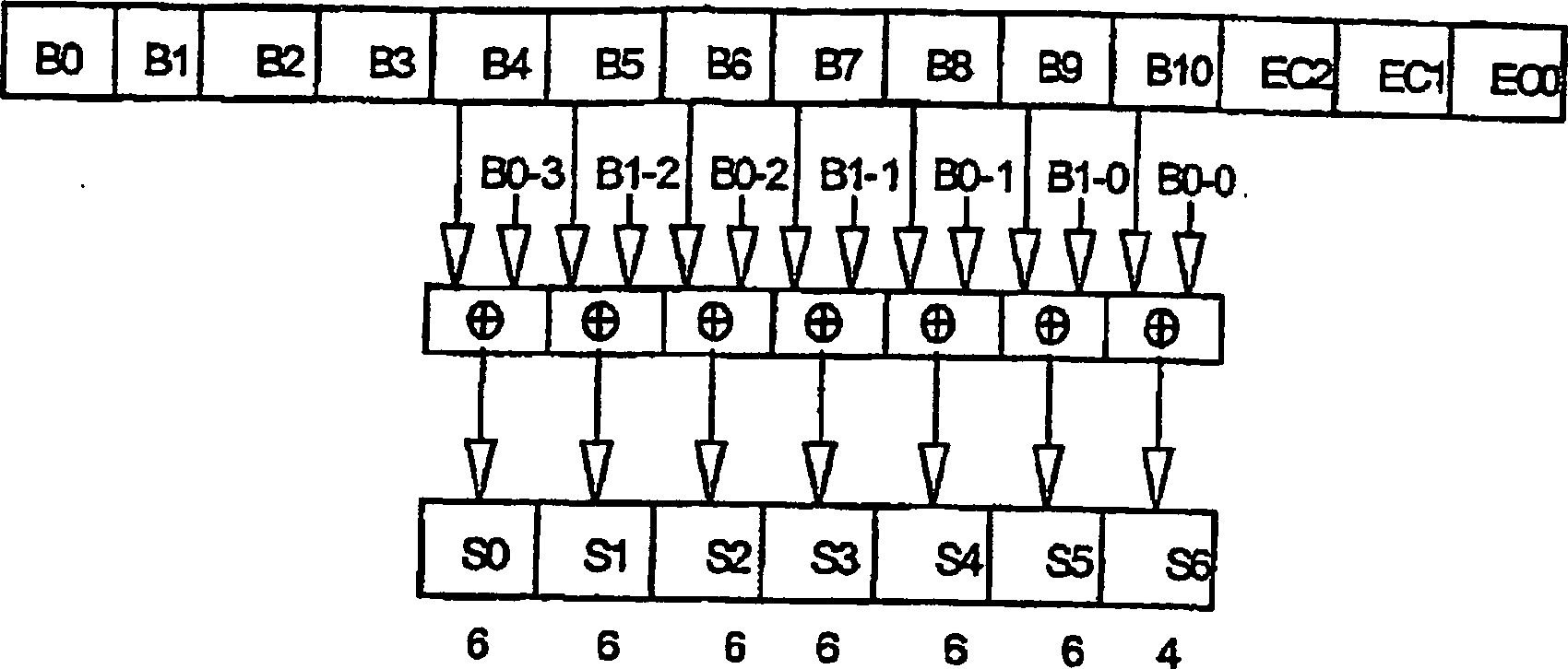
Die SAW-Etikett-Codes werden verschlüsselt, um weitgehend unterschiedliche Impulsmuster für jeden Code einer Reihe von eng miteinander verwandten Etiketten trotz der Tatsache, dass bestimmte Felder dieselben sein werden, zu erzeugen. Die Verwendung von unterschiedlichen Impulsmustern unterstützt die Identifizierung der einzelnen SAW-Etiketten in einem Ensemble solcher Etiketten. Das B0- und B1-Feld wurden für die Verwendung der Verschlüsselungscodes in dem veranschaulichten Beispiel ausgewählt, da angenommen wird, dass diese von einem Ensemble von SAW-Etiketten zu einem anderen Ensemble wechseln. Um das Verwenden desselben Verschlüsselungscodes in mehreren Feldern zu vermeiden, wird der Code geschoben, um verschiedene Codes in SO bis S6 zu erzeugen. Folglich sind die verschlüsselten Codes sogar dann nicht identisch, wenn unverschlüsselte Felder identisch sein könnten.The SAW label codes are encrypted, to make widely different pulse patterns for each code in a series of closely related labels despite the fact that certain Fields will be the same. The use of different Impulse patterns supported the identification of the individual SAW labels in an ensemble such labels. The B0 and B1 fields were for the use of the encryption codes in the illustrated example, since it is assumed that these from an ensemble of SAW labels to another ensemble switch. To use the same encryption key in multiple fields To avoid, the code is pushed to different codes in SO to produce S6. Consequently, the encrypted codes are not even then identical if unencrypted Fields could be identical.
Das SAW-Etikett Antwortsignalformat eines 61-Bit Datencodes ist in Tabelle 5 gezeigt. Die allgemeinen Felder des in Tabelle 5 gezeigten 64-Bit Codes werden in der Reihenfolge von B0 bis B3 gefolgt von den verschlüsselten Feldern SO bis S6 übertragen. Die Übertragung der 16 Fehlerprüfbits wird dem 61-Bit Datenfeld folgen.The SAW label Response signal format of a 61-bit data code is shown in Table 5 shown. The general fields of the 64-bit shown in Table 5 Codes are followed in the order from B0 to B3 followed by the encrypted ones Transfer fields SO to S6. The transfer the 16 error check bits will follow the 61 bit data field.
Tabelle
5 64-Bit
Entschlüsselung 
Angenommen, B0 und B1 werden richtig empfangen (wie nachfolgend durch die Fehlerprüfung verifiziert wird), dann können die verschlüsselten Felder durch Umkehren des Vorgangs des Verschlüsselns entschlüsselt werden, wie in Tabelle 6 veranschaulicht ist.Accepted, B0 and B1 are received correctly (as verified by the error check below) will), then you can the encrypted Decrypting fields by reversing the process of encrypting, as illustrated in Table 6.
Tabelle
6 61-Bit
Entschlüsselungsvorgang 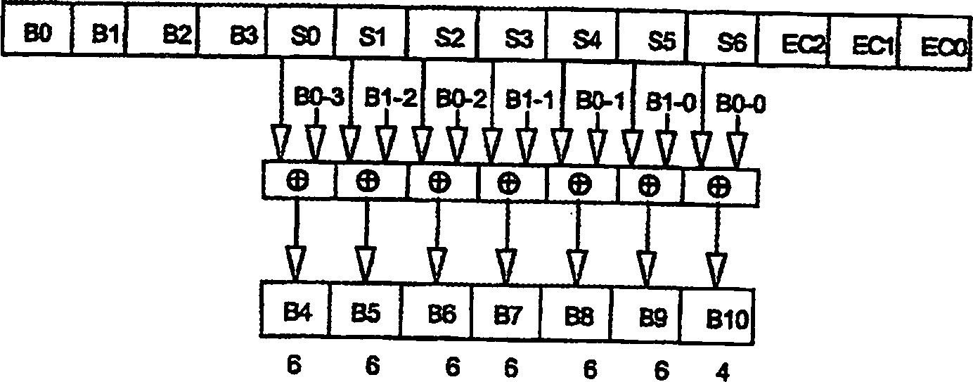
Wendet
man sich nun
Obwohl die vorliegende Erfindung detailliert beschrieben wurde, wird der Fachmann verstehen, dass er verschiedene Abänderungen, Ersetzungen und Veränderungen hierein vornehmen kann, ohne den Schutzbereich in seiner breitesten Form zu verlassen.Even though the present invention has been described in detail, the Professional understand that he has various modifications, substitutions and changes it is possible to do without the scope of protection at its widest Leave form.
Claims (16)
Applications Claiming Priority (3)
| Application Number | Priority Date | Filing Date | Title |
|---|---|---|---|
| US268108 | 2002-10-09 | ||
| US10/268,108 US6958696B2 (en) | 2002-10-09 | 2002-10-09 | Transfer function system for determining an identifier on a surface acoustic wave identification tag and method of operating the same |
| PCT/US2003/030692 WO2004086322A1 (en) | 2002-10-09 | 2003-09-30 | A transfer function system for determining an identifier on a surface acoustic wave identification tag and method of operating the same |
Publications (2)
| Publication Number | Publication Date |
|---|---|
| DE60312877D1 DE60312877D1 (en) | 2007-05-10 |
| DE60312877T2 true DE60312877T2 (en) | 2007-12-06 |
Family
ID=32092406
Family Applications (1)
| Application Number | Title | Priority Date | Filing Date |
|---|---|---|---|
| DE60312877T Expired - Lifetime DE60312877T2 (en) | 2002-10-09 | 2003-09-30 | TRANSMISSION FUNCTION SYSTEM FOR DETERMINING THE IDENTIFICATION OF A SURFACE WAVE IDENTIFICATION LABEL AND METHOD FOR OPERATING THE SAME |
Country Status (13)
| Country | Link |
|---|---|
| US (1) | US6958696B2 (en) |
| EP (1) | EP1552486B1 (en) |
| JP (1) | JP2006507610A (en) |
| KR (1) | KR100788181B1 (en) |
| CN (1) | CN100498856C (en) |
| AT (1) | ATE358309T1 (en) |
| AU (1) | AU2003275287B2 (en) |
| BR (1) | BR0315238A (en) |
| CA (1) | CA2500443A1 (en) |
| DE (1) | DE60312877T2 (en) |
| EA (1) | EA200500465A1 (en) |
| NZ (1) | NZ539135A (en) |
| WO (1) | WO2004086322A1 (en) |
Cited By (1)
| Publication number | Priority date | Publication date | Assignee | Title |
|---|---|---|---|---|
| WO2019157542A1 (en) * | 2018-02-16 | 2019-08-22 | Sensideon Gmbh | Method for reading out different identification elements in a wireless fashion |
Families Citing this family (33)
| Publication number | Priority date | Publication date | Assignee | Title |
|---|---|---|---|---|
| US7525453B2 (en) * | 2000-10-17 | 2009-04-28 | Henty David L | Computer system with enhanced range passive wireless keyboard |
| US6997388B2 (en) * | 2003-02-19 | 2006-02-14 | Inksure Rf Inc. | Radio frequency data carrier and method and system for reading data stored in the data carrier |
| US8174366B2 (en) * | 2003-03-03 | 2012-05-08 | Veroscan, Inc. | Interrogator and interrogation system employing the same |
| US7671744B2 (en) * | 2003-03-03 | 2010-03-02 | Veroscan, Inc. | Interrogator and interrogation system employing the same |
| US7893840B2 (en) * | 2003-03-03 | 2011-02-22 | Veroscan, Inc. | Interrogator and interrogation system employing the same |
| US7019650B2 (en) * | 2003-03-03 | 2006-03-28 | Caducys, L.L.C. | Interrogator and interrogation system employing the same |
| US8063760B2 (en) * | 2003-03-03 | 2011-11-22 | Veroscan, Inc. | Interrogator and interrogation system employing the same |
| US7764178B2 (en) * | 2003-03-03 | 2010-07-27 | Veroscan, Inc. | Interrogator and interrogation system employing the same |
| US8542717B2 (en) | 2003-03-03 | 2013-09-24 | Veroscan, Inc. | Interrogator and interrogation system employing the same |
| NZ546461A (en) * | 2003-10-08 | 2008-06-30 | Rf Saw Components Inc | A single phase unidirectional surface acoustic wave transducer and improved reflectors |
| WO2005086072A1 (en) | 2004-03-03 | 2005-09-15 | Caducys, L.L.C. | Interrogator and interrogation system employing the same |
| US20060017545A1 (en) * | 2004-03-26 | 2006-01-26 | Volpi John P | Radio frequency identification interrogation systems and methods of operating the same |
| US7369014B1 (en) * | 2004-05-12 | 2008-05-06 | Joseph C. Fehsenfeld | Flexible surface acoustic wave device |
| FR2871241B1 (en) * | 2004-06-07 | 2007-01-26 | Commissariat Energie Atomique | ULB LOCATION SYSTEM FOR AVALANCHES VICTIMS RELIEF |
| US7501948B2 (en) * | 2004-09-29 | 2009-03-10 | Lone Star Ip Holdings, Lp | Interrogation system employing prior knowledge about an object to discern an identity thereof |
| US7506813B2 (en) * | 2005-01-06 | 2009-03-24 | Quad/Graphics, Inc. | Resonator use in the print field |
| US20070035383A1 (en) * | 2005-08-09 | 2007-02-15 | Roemerman Steven D | Radio frequency identification interrogation systems and methods of operating the same |
| US20070139165A1 (en) * | 2005-12-19 | 2007-06-21 | Honeywell International, Inc. | Acoustic wave device used as RFID and as sensor |
| KR100775763B1 (en) * | 2006-03-21 | 2007-11-09 | 엘지전자 주식회사 | Tag for RFID and Fabricating method thereof |
| JP4899691B2 (en) * | 2006-07-28 | 2012-03-21 | 富士ゼロックス株式会社 | Authenticator true / false judgment system, identification system and interrogator |
| KR100833550B1 (en) * | 2006-11-07 | 2008-05-29 | 인하대학교 산학협력단 | SAW based Chipless Passive RFID Tag Using Cellulose Paper as the Substrate and Method for Manufaturing the Cellulose Paper |
| US7755491B2 (en) * | 2007-08-13 | 2010-07-13 | Veroscan, Inc. | Interrogator and interrogation system employing the same |
| JP5498397B2 (en) * | 2007-12-19 | 2014-05-21 | コーニンクレッカ フィリップス エヌ ヴェ | Apparatus and method for identifying an object |
| US20100225449A1 (en) * | 2009-03-06 | 2010-09-09 | Rf Saw, Inc. | Radio-Frequency Surface-Acoustic-Wave Identification Tag and System |
| US8466776B2 (en) * | 2010-07-01 | 2013-06-18 | The United States Of America As Represented By The Administrator Of The National Aeronautics And Space Administration | Extended range passive wireless tag system and method |
| US9035774B2 (en) | 2011-04-11 | 2015-05-19 | Lone Star Ip Holdings, Lp | Interrogator and system employing the same |
| TW201508644A (en) * | 2013-08-16 | 2015-03-01 | guan-rong Zhong | Omnidirectional surface acoustic wave wireless recognition module |
| US9647636B1 (en) * | 2016-04-01 | 2017-05-09 | Intel Corporation | Piezoelectric package-integrated delay lines for radio frequency identification tags |
| CN107329142B (en) * | 2017-05-08 | 2021-04-02 | 上海交通大学 | SAW RFID tag distance measurement method based on multi-frequency phase difference |
| RU2661288C1 (en) * | 2017-08-30 | 2018-07-13 | Акционерное общество "Научно-производственное предприятие "Радар ммс" | Method of the objects radio-frequency identification and system for its implementation |
| EP3765834A4 (en) * | 2018-03-13 | 2021-12-15 | University of Louisville | Frequency selective surfaces for tracking, labeling and identification |
| FR3079053B1 (en) * | 2018-03-16 | 2020-03-27 | Frec'n'sys | COMPOSITE SUBSTRATES FOR SURFACE ACOUSTIC WAVE LABEL DEVICES FOR RFID AND SENSOR APPLICATIONS |
| CN108346263A (en) * | 2018-04-17 | 2018-07-31 | 上海海事大学 | Container ship hazardous materials transportation warning system based on sound wave identification technology and method |
Family Cites Families (8)
| Publication number | Priority date | Publication date | Assignee | Title |
|---|---|---|---|---|
| US5734326A (en) * | 1994-11-28 | 1998-03-31 | The United States Of America As Represented By The Secretary Of The Army | Recognition tag for use in a system for identifying distant items |
| US6407695B1 (en) * | 1996-05-07 | 2002-06-18 | Hera Rotterdam B.V. | Process for carrying out a non-contact remote enquiry |
| KR100307995B1 (en) * | 1996-05-29 | 2002-03-21 | 만골드 안톤 | Wireless transmission device from moving object |
| US5821425A (en) * | 1996-09-30 | 1998-10-13 | The United States Of America As Represented By The Secretary Of The Army | Remote sensing of structural integrity using a surface acoustic wave sensor |
| US6107910A (en) * | 1996-11-29 | 2000-08-22 | X-Cyte, Inc. | Dual mode transmitter/receiver and decoder for RF transponder tags |
| US6633226B1 (en) * | 1997-08-18 | 2003-10-14 | X-Cyte, Inc. | Frequency hopping spread spectrum passive acoustic wave identification device |
| DE19860058C1 (en) * | 1998-12-23 | 2000-03-30 | Siemens Ag | Radio pollable surface wave component with optimal code range, e.g. for level measurement |
| DE19911369C2 (en) * | 1999-03-15 | 2003-04-03 | Nanotron Ges Fuer Mikrotechnik | Surface-wave converter device and identification system herewith |
-
2002
- 2002-10-09 US US10/268,108 patent/US6958696B2/en not_active Expired - Lifetime
-
2003
- 2003-09-30 CA CA002500443A patent/CA2500443A1/en not_active Abandoned
- 2003-09-30 AU AU2003275287A patent/AU2003275287B2/en not_active Expired - Fee Related
- 2003-09-30 JP JP2004569973A patent/JP2006507610A/en active Pending
- 2003-09-30 NZ NZ539135A patent/NZ539135A/en unknown
- 2003-09-30 WO PCT/US2003/030692 patent/WO2004086322A1/en active IP Right Grant
- 2003-09-30 AT AT03759563T patent/ATE358309T1/en not_active IP Right Cessation
- 2003-09-30 DE DE60312877T patent/DE60312877T2/en not_active Expired - Lifetime
- 2003-09-30 BR BR0315238-3A patent/BR0315238A/en not_active IP Right Cessation
- 2003-09-30 EP EP03759563A patent/EP1552486B1/en not_active Expired - Lifetime
- 2003-09-30 EA EA200500465A patent/EA200500465A1/en unknown
- 2003-09-30 KR KR1020057006190A patent/KR100788181B1/en not_active IP Right Cessation
- 2003-09-30 CN CNB038240025A patent/CN100498856C/en not_active Expired - Fee Related
Cited By (1)
| Publication number | Priority date | Publication date | Assignee | Title |
|---|---|---|---|---|
| WO2019157542A1 (en) * | 2018-02-16 | 2019-08-22 | Sensideon Gmbh | Method for reading out different identification elements in a wireless fashion |
Also Published As
| Publication number | Publication date |
|---|---|
| ATE358309T1 (en) | 2007-04-15 |
| EA200500465A1 (en) | 2006-06-30 |
| AU2003275287B2 (en) | 2008-07-17 |
| KR100788181B1 (en) | 2007-12-26 |
| US20040075560A1 (en) | 2004-04-22 |
| EP1552486B1 (en) | 2007-03-28 |
| US6958696B2 (en) | 2005-10-25 |
| KR20050055759A (en) | 2005-06-13 |
| DE60312877D1 (en) | 2007-05-10 |
| NZ539135A (en) | 2007-06-29 |
| WO2004086322A1 (en) | 2004-10-07 |
| CN100498856C (en) | 2009-06-10 |
| JP2006507610A (en) | 2006-03-02 |
| CN1689053A (en) | 2005-10-26 |
| EP1552486A1 (en) | 2005-07-13 |
| BR0315238A (en) | 2005-08-23 |
| AU2003275287A1 (en) | 2004-10-18 |
| CA2500443A1 (en) | 2004-10-07 |
| EP1552486A4 (en) | 2005-12-21 |
Similar Documents
| Publication | Publication Date | Title |
|---|---|---|
| DE60312877T2 (en) | TRANSMISSION FUNCTION SYSTEM FOR DETERMINING THE IDENTIFICATION OF A SURFACE WAVE IDENTIFICATION LABEL AND METHOD FOR OPERATING THE SAME | |
| DE69818818T2 (en) | READER FOR IDENTIFICATION IN A RADIO SYSTEM | |
| EP0746775B1 (en) | Identification tag operating with acoustic surface waves | |
| DE69909258T2 (en) | READER FOR IDENTIFYING OBJECTS | |
| DE60023561T2 (en) | ELECTRONIC LABEL READING SYSTEM | |
| DE69831057T2 (en) | MULTIPLE LABEL READING SYSTEM | |
| EP2739989B1 (en) | Method and system for locating rfid tags | |
| DE1274392B (en) | Device for recognizing vehicles, in particular railroad cars | |
| DE3305685A1 (en) | CONTINUITY MONITORING SYSTEM WORKING WITH CODED IDENTIFICATION TOKENS | |
| DE3438051C2 (en) | ||
| EP0773451A1 (en) | Wireless interrogating system operating with acoustic surface waves | |
| DE3438050C2 (en) | ||
| EP0458097B1 (en) | Data transmission method | |
| DE2556625C3 (en) | ||
| DE2439494A1 (en) | TRANSPONDER WITH LARGE SIGN CAPACITY | |
| WO1998021685A2 (en) | Shopping basket scanner | |
| EP0651344B1 (en) | Identifying system with ID-tags working with surface acoustic waves | |
| DE1813319C3 (en) | Device for recognizing vehicles located in the area of an interrogation device | |
| DE10352734A1 (en) | Radio frequency identification device | |
| DE1946247C3 (en) | Interrogation-response system for various interrogation codes that works according to the radio re-radiation principle | |
| DE102019110373A1 (en) | PRINTED RFID TAG ANTENNA FIELD WITH INTERFERENCE FIELDS | |
| DE2712595C3 (en) | Radar response beacon with electroacoustic delay line with multiple reflection for pulse coding | |
| DE102014117791B4 (en) | Passive reader for identification by means of electromagnetic waves (RFID), passive RFID tag and transmission and reception method by means of extended pulse interval coding (PIE) | |
| DE60210062T2 (en) | COMMUNICATION BETWEEN A TRANSPONDER AND A QUERY UNIT | |
| EP0228424A1 (en) | Circuit for exploiting telecontrol signals |
Legal Events
| Date | Code | Title | Description |
|---|---|---|---|
| 8364 | No opposition during term of opposition |