DE602004003342T2 - METHOD AND APPARATUS FOR THE MANUFACTURE OF OPTICAL TRANSMISSION MEDIA - Google Patents
METHOD AND APPARATUS FOR THE MANUFACTURE OF OPTICAL TRANSMISSION MEDIA Download PDFInfo
- Publication number
- DE602004003342T2 DE602004003342T2 DE602004003342T DE602004003342T DE602004003342T2 DE 602004003342 T2 DE602004003342 T2 DE 602004003342T2 DE 602004003342 T DE602004003342 T DE 602004003342T DE 602004003342 T DE602004003342 T DE 602004003342T DE 602004003342 T2 DE602004003342 T2 DE 602004003342T2
- Authority
- DE
- Germany
- Prior art keywords
- polymer
- cylindrical volume
- prepolymer
- outer tube
- fiber
- Prior art date
- Legal status (The legal status is an assumption and is not a legal conclusion. Google has not performed a legal analysis and makes no representation as to the accuracy of the status listed.)
- Expired - Fee Related
Links
Classifications
-
- G—PHYSICS
- G02—OPTICS
- G02B—OPTICAL ELEMENTS, SYSTEMS OR APPARATUS
- G02B6/00—Light guides; Structural details of arrangements comprising light guides and other optical elements, e.g. couplings
- G02B6/02—Optical fibres with cladding with or without a coating
- G02B6/02033—Core or cladding made from organic material, e.g. polymeric material
- G02B6/02038—Core or cladding made from organic material, e.g. polymeric material with core or cladding having graded refractive index
-
- B—PERFORMING OPERATIONS; TRANSPORTING
- B29—WORKING OF PLASTICS; WORKING OF SUBSTANCES IN A PLASTIC STATE IN GENERAL
- B29D—PRODUCING PARTICULAR ARTICLES FROM PLASTICS OR FROM SUBSTANCES IN A PLASTIC STATE
- B29D11/00—Producing optical elements, e.g. lenses or prisms
- B29D11/00663—Production of light guides
- B29D11/00682—Production of light guides with a refractive index gradient
-
- G—PHYSICS
- G02—OPTICS
- G02B—OPTICAL ELEMENTS, SYSTEMS OR APPARATUS
- G02B1/00—Optical elements characterised by the material of which they are made; Optical coatings for optical elements
- G02B1/04—Optical elements characterised by the material of which they are made; Optical coatings for optical elements made of organic materials, e.g. plastics
- G02B1/045—Light guides
-
- G—PHYSICS
- G02—OPTICS
- G02B—OPTICAL ELEMENTS, SYSTEMS OR APPARATUS
- G02B6/00—Light guides; Structural details of arrangements comprising light guides and other optical elements, e.g. couplings
- G02B6/44—Mechanical structures for providing tensile strength and external protection for fibres, e.g. optical transmission cables
- G02B6/4401—Optical cables
- G02B6/4403—Optical cables with ribbon structure
Abstract
Description
Diese Anmeldung beansprucht die Priorität einer U.S. Provisional-Anmeldung der laufenden Nummer 60/446,369; angemeldet am 10. Februar 2003.These Application claims the priority of U.S. Pat. Provisional Application the serial number 60 / 446,369; registered on February 10, 2003.
Hintergrund der Erfindungbackground the invention
Die Herstellung von optischen Fasern mit einem Gradienten-Brechungsindex (gradedrefractive-index, GRIN) ist sehr gut bekannt. Zum Beispiel offenbaren die U.S. Patent Nr. 5,760,139 und die U.S. Patent Nr. 5,783,636 eine Anzahl von Verfahren für die Herstellung von optischen Fasern mit einem Gradienten-Brechungsindex. In solch einer optischen Faser ist oftmals eine Dotiersubstanz in einem Polymer verteilt, so daß ein Konzentrationsgradient in Richtung vom Zentrum zur Peripherie vorliegt. Üblicherweise ist die Dotiersubstanz ein Material, welches einen höheren Brechungsindex hat als das Fluorpolymer und die Dotiersubstanz ist so verteilt, so daß sie einen Konzentrationsgradienten hat, so daß die Konzentration von der Dotiersubstanz in Richtung von der Mitte der optischen Faser zur Peripherie hin abnimmt. Infolgedessen kann eine optische Faser mit einem Gradienten-Brechungsindex hergestellt werden, indem die Dotiersubstanz in der Mitte angeordnet wird und die Dotiersubstanz in Richtung Peripherie diffundiert. In anderen Fällen wird die optische Faser mit einem Gradiente-Brechungsindex gebildet, wobei die Dotiersubstanz ein Material ist, welches einen geringeren Brechungsindex hat als das Fluorpolymer und die Dotiersubstanz so verteilt ist, so daß sie einen Konzentrationsgradienten hat, so daß die Konzentration von der Dotiersubstanz in Richtung von der Peripherie der optischen Fasern zur Mitte hin abnimmt. Infolgedessen wird eine optische Faser mit einem Gradienten-Brechungsindex hergestellt, indem die Dotiersubstanz von der Peripherie in Richtung Mitte diffundiert.The Production of optical fibers with a gradient index of refraction (gradedrefractive-index, GRIN) is very well known. For example U.S. Pat. U.S. Pat. No. 5,760,139 and U.S. Pat. Patent No. 5,783,636 a number of methods for the production of optical fibers with a gradient refractive index. In such an optical fiber is often a dopant in a polymer distributed so that a Concentration gradient in the direction from the center to the periphery is present. Usually the dopant is a material which has a higher refractive index has as the fluoropolymer and the dopant is distributed so so that you has a concentration gradient so that the concentration of the Dopant in the direction from the center of the optical fiber to Periphery decreases. As a result, an optical fiber having a gradient refractive index can be prepared by placing the dopant in the middle and the dopant is diffused toward the periphery. In other cases is the optical fiber formed with a gradient of refractive index, wherein the dopant is a material having a lower Refractive index has as the fluoropolymer and the dopant so is distributed so that she has a concentration gradient so that the concentration of the Dopant in the direction of the periphery of the optical fibers decreases towards the middle. As a result, an optical fiber with a gradient refractive index prepared by the dopant from the periphery in the direction Center diffused.
Das U.S. Patent Nr. 5,760,139 und das U.S. Patent Nr. 5,783,636 offenbart zahlreiche Verfahren für die Herstellung einer optischen Kunststofffaser mit einem Gradientenindex. Ein erstes Verfahren umfaßt das Schmelzen des Fluorpolymers, Einspritzen der Dotiersubstanz oder eines Fluorpolymers, das die Dotiersubstanz enthält, in die Mitte der Schmelze des Fluorpolymers und dann Formung der Schmelze während, oder nach, der Diffusion der Dotiersubstanz. In diesem Fall kann die Dotiersubstanz in die Mitte injiziert werden, nicht nur um nur eine Schicht zu bilden, aber auch, um so einen Stab-ähnlichen Grundkörper zu bilden, wie zum Beispiel eine Vorform einer optischen Faser, oder durch das Schmelzspinnverfahren, welches für die Bildung einer optischen Faser geeignet ist. Ein zweites Verfahren umfaßt die Tauchbeschichtung der Dotiersubstanz oder des Fluorpolymers, welches die Dotiersubstanz enthält, auf einen Kern, der aus dem Fluorpolymer durch Schmelzspinnen oder Zugumformen gebildet wurde. Ein drittes Verfahren umfaßt die Bildung eines hohlen Rohrs des Fluorpolymers, indem ein rotierendes Glasröhrchen oder ähnliches verwendet wird, Füllen des Polymerröhrchens mit einer Monomerphase, welches die Dotiersubstanz ergibt oder des Fluorpolymers, welches die Dotiersubstanz enthält, und dann Polymerisierung der Monomerphase während das Polymerröhrchen bei geringer Geschwindigkeit rotiert. In dem Fall von Grenzflächen-Gelpolymerisation, in dem Polymerisierungsschritt, schwillt das Röhrchen von dem Fluorpolymer in der Monomerphase auf und bildet eine Gelphase, und die Monomermoleküle werden polymerisiert, während sie vorzugsweise in die Gelphase diffundieren. Ein viertes Verfahren umfaßt die Verwendung von zwei Arten von Monomeren mit unterschiedlichen Reaktivitäten. Ein Monomer bildet das Fluorpolymer und das andere Monomer bildet die Dotiersubstanz. Die Polymerisierungsreaktion wird so ausgeführt, so dass die Anteile der Zusammensetzung des resultierenden Fluorpolymers zu dem resultierenden Dotiermittel kontinuierlich in der Richtung von der Peripherie zu der Mitte variieren. Ein fünftes Verfahren umfaßt das Warmziehen oder das Schmelz-Extrudieren eines Gemisches des Fluorpolymers und der Dotiersubstanz, welches durch das homogene Mischen der beiden oder durch das homogene Mischen der beiden in einem Lösungsmittel erhalten wurde und dann das Entfernen des Lösungsmittels durch das Mittel der Evaporation, in Fasern, und dann (oder unverzüglich nach der Bildung der Fasern) das Inkontaktbringen der Fasern mit einem inerten Gas unter Erwärmung, um die Dotiersubstanz von der Oberfläche zu evaporieren und dadurch einen Gradienten-Brechungsindex zu bilden. Wahlweise werden die Fasern in einem Lösungsmittel untergetaucht, welches nicht das Fluorpolymer auflöst, aber die Dotiersubstanz auflöst, so daß die Dotiersubstanz aus der Oberfläche der Fasern aufgelöst wird, so daß ein Gradienten-Brechungsindex gebildet wird. Ein sechstes Verfahren umfaßt die Beschichtung eines Stabes oder einer Faser des Fluorpolymers mit nur der Dotiersubstanz, welche einen kleineren Brechungsindex hat als das Fluorpolymer, oder einem Gemisch von dem Fluorpolymer und der Dotiersubstanz und dann die Diffusion der Dotiersubstanz durch Erwärmung, um einen Gradienten-Brechungsindex zu bilden. Ein siebtes Verfahren umfaßt das Mischen eines Polymers mit einem hohen Brechungsindex und einem Polymer mit einem geringen Brechungsindex durch Warmschmelze oder in einem Zustand einer Lösung, umfassend ein Lösungsmittel, und ihrer Diffusion ineinander, während (oder nach) dem Extrudieren vieler Schichten in einen Zustand, so daß jede ein unterschiedliches Mischungsverhältnis hat, um letzten Endes eine Faser zu erhalten, die einen Gradienten-Brechungsindex hat. In diesem Fall kann das Polymer mit hohem Brechungsindex ein Fluorpolymer sein und das Polymer mit geringem Brechungsindex kann die Dotiersubstanz sein. Im Hinblick auf diese Herstellungsmethoden ist die Rate der Faserherstellung nicht mehr als ungefähr 1 Meter pro Minute und daher sind diese Herstellungsmethoden kommerziell nicht praktikabel.US Pat. No. 5,760,139 and US Pat. No. 5,783,636 disclose numerous methods for producing a graded index plastic optical fiber. A first method comprises melting the fluoropolymer, injecting the dopant or a fluoropolymer containing the dopant into the center of the melt of the fluoropolymer and then forming the melt during, or after, the diffusion of the dopant. In this case, the dopant may be injected into the center, not only to form only one layer, but also to form a rod-like body, such as an optical fiber preform, or by the melt spinning method which is used for the formation of an optical fiber is suitable. A second method comprises dip coating the dopant or fluoropolymer containing the dopant onto a core formed from the fluoropolymer by melt spinning or draw forming. A third method involves forming a hollow tube of the fluoropolymer by using a rotating glass tube or the like, filling the polymer tube with a monomer phase yielding the dopant or the fluoropolymer containing the dopant, and then polymerizing the monomer phase while the polymer tube low speed rotates. In the case of interfacial gel polymerization, in the polymerization step, the tube swells from the fluoropolymer in the monomer phase and forms a gel phase, and the monomer molecules are polymerized while preferentially diffusing into the gel phase. A fourth method involves the use of two types of monomers with different reactivities. One monomer forms the fluoropolymer and the other monomer forms the dopant. The polymerization reaction is carried out so that the proportions of the composition of the resulting fluoropolymer to the resulting dopant vary continuously in the direction from the periphery to the center. A fifth method involves hot drawing or melt extruding a mixture of the fluoropolymer and the dopant obtained by homogeneously mixing the two or by homogeneously mixing the two in a solvent and then removing the solvent by the means of evaporation, in fibers, and then (or immediately after the formation of the fibers) contacting the fibers with an inert gas under heating to evaporate the dopant from the surface and thereby form a gradient refractive index. Optionally, the fibers are submerged in a solvent which does not dissolve the fluoropolymer but dissolve the dopant so that the dopant is dissolved from the surface of the fibers to form a gradient refractive index. A sixth method involves coating a rod or fiber of the fluoropolymer with only the dopant having a lower refractive index than the fluoropolymer, or a mixture of the fluoropolymer and dopant, and then thermally diffusing the dopant to a gradient refractive index to build. A seventh method comprises mixing a high refractive index polymer and a low refractive index polymer by hot melt or in a state of a solution comprising a solvent and diffusion into one another during (or after) extruding many layers into a state, so that each has a different mixing ratio to ultimately obtain a fiber having a gradient refractive index. In this case, the high refractive index polymer may be a fluoropolymer and the polymer with low refractive index may be the dopant. In view of these production methods, the rate of fiber production is not more than about 1 meter per minute, and therefore these production methods are not commercially viable.
Das U.S. Patent Nr. 6,254,808 beschreibt einen kontinuierlichen Extrusionsprozeß, welcher in der Lage ist, eine optische Gradientenindex Kunststofffaser in Geschwindigkeiten von mindestens 1 m/Sek. bei 250 Mikrometer Durchmesse Faser herzustellen, die erwärmte Länge, über welche die Diffusion zu beobachten ist, ist ungefähr 400 cm. Um die notwendige Diffusion während der kurzen Einwirkzeit zu erreichen, ist die Temperatur auf 270°C erhöht worden. In diesem Fall wird erwartet, daß dort eine signifikante thermale Degradation der Lichtwellenleiterübertragung der Faser vorliegt. Die Ergebnisse für die Lichtwellenleiterübertragung werden in diesem Patent nicht zur Verfügung gestellt.The U.S. Patent No. 6,254,808 describes a continuous extrusion process which is able to use an optical graded index plastic fiber in Speeds of at least 1 m / sec. at 250 microns diameter Produce fiber that heated Length, over which the diffusion is about 400 cm. To the necessary Diffusion during To reach the short exposure time, the temperature has been increased to 270 ° C. In this case, it is expected that there is a significant thermal Degradation of the optical fiber transmission of the fiber is present. The results for the optical fiber transmission will be not available in this patent posed.
Das U.S. Patent Nr. 6,265,018 beschreibt ein Verfahren, welches für die Herstellung von Gradientenindex polymeren optischen Fasern durch das Ziehen aus einer Vorform oder durch Extrusion geeignet ist. Die Faser ist in einem Polymerröhrchen eingeschlossen, welches bei einer Temperatur oberhalb der mechanisch stabil ist, bei der die Diffusion der Dotiersubstanz ausgeführt wird. Eine Aufrollung der in Röhrchen eingeschlossenen Faser wird erzeugt, plaziert in einem geheizten Ofen, um die optimale Menge der Diffusion zu bewirken und dann wird sie aus dem Ofen entfernt. Im Ergebnis ist dies ein diskontinuierliches Verfahren (batch process). Jedoch ist es sehr wünschenswert, einen kontinuierlichen Prozeß zu haben, um die Arbeitskosten zu minimieren und einen noch wirtschaftlicheren Prozess zu Stande zu bringen.The U.S. Patent No. 6,265,018 describes a process used for the production of gradient index of polymeric optical fibers by drawing from a preform or by extrusion is suitable. The fiber is in a polymer tube included, which at a temperature above the mechanically stable is, in which the diffusion of the dopant is carried out. A reel of tubes trapped fiber is generated, placed in a heated Oven to effect the optimum amount of diffusion and then she removed from the oven. As a result, this is a discontinuous Process (batch process). However, it is very desirable to have a continuous one Process too have to minimize labor costs and an even more economical Process to accomplish.
Die U.S. veröffentlichte Anmeldungsnummer 20020041042 beschreibt ein kontinuierliches, Hochgeschwindigkeits-Extrusionsverfahren einer Gradientenfaser und wird hierin durch Bezugnahme in seiner Gesamtheit aufgenommen. Zwei oder mehrere konzentrische Schichten von Polymeren mit zumindest einem Additiv, werden in einem Polymerröhrchen koextrudiert, welches bei einer Temperatur gut über der Glasübergangstemperatur des inneren Polymers liegt, beständig ist. Diese Faser wird kontinuierlich mit hoher Geschwindigkeit auf eine rotierende Trommel innerhalb eines beheizten Ofens gespeist und nach einer vorgeschriebenen Aufenthaltszeit der Faser von der Trommel abgespeist, aus dem geheizten Ofen und wird kontinuierlich auf eine Spule gespult. Wenn die Spule aufgefüllt ist, wird die Faser automatisch auf eine neue Spule gespeist. Auf diese Art und Weise kann eine kontinuierliche Herstellung zu Stande gebracht werden.The U.S. published Application No. 20020041042 describes a continuous, high-speed extrusion process a gradient fiber and is incorporated herein by reference Entity recorded. Two or more concentric layers of polymers with at least one additive are coextruded in a polymer tube, which at a temperature well above the glass transition temperature of the inner polymer is stable is. This fiber is continuously growing at high speed a rotating drum fed within a heated oven and after a prescribed residence time of the fiber of the Drum is fed from the heated oven and is continuously spooled on a spool. When the bobbin is filled, the fiber becomes automatic fed to a new coil. In this way one can be made continuous production.
Die obigen Herstellungsverfahren verwenden das eine oder andere der zwei Grundverfahren – Ziehen der Faser aus einer Vorform und Extrusion der Faser. Darüber hinaus ist es nützlich, das Polymermaterial in zwei Klassen zu teilen – organische Polymere, üblicherweise Acryl und perfluoriertes Polymer. In Bezug auf organische Polymerfasern können GRIN Vorformen durch verschiedene Methoden hergestellt werden. Jedoch ist die Geschwindigkeit sehr eingeschränkt, bei welcher die gewünschte Faser, mit 0,2 mm bis 1,0 mm Durchmesser gezogen werden kann. Im Ergebnis ist es kein großtechnisch praktikabler Prozeß. Verschiedene Versuche, um organische GRIN polymere optische Fasern (POF) zu koextrudieren, sind mit unterschiedlichen Ausmaßen einer verbesserten Herstellungsrate gemacht worden. Eine Methode, die U.S. veröffentlichte Anmeldungsnummer 20020041042 beschreibt ein hochgeschwindigkeits, kontinuierliches, preiswertes Verfahren der Herstellung von Acryl GRIN POF mit einer guten Lichtwellenleiterübertragung. Die theoretische Absorption von Licht mit einer Wellenlänge von 655 nm in einer Acrylpolymerfaser ist ungefähr 100 dB/km. Eine GRIN Faser, die aus einer Vorform gezogen wurde, hat gezeigt, daß die experimentell erreichbare optische Absorption innerhalb von 30 % des obigen theoretischen Wertes sein kann. Eine Acryl GRIN Faser kann auch mit einer ähnlichen Lichtabsorption extrudiert werden. Somit kann eine organische GRIN polymere optische Faser in großtechnisch praktikablen Geschwindigkeiten mit best möglichen optischen Eigenschaften hergestellt werden.The The above manufacturing methods use one or the other of the two basic procedures - pulling the Fiber from a preform and extrusion of the fiber. Furthermore is it useful to divide the polymer material into two classes - organic polymers, usually Acrylic and perfluorinated polymer. Regarding organic polymer fibers can GRIN preforms are made by various methods. However, that is very limited the speed at which the desired fiber, can be pulled with 0.2 mm to 1.0 mm diameter. In the result It is not a large scale workable process. Various attempts to organic GRIN polymeric optical fibers To coextrude (POF), are of different dimensions improved production rate. A method that U.S. published Application number 20020041042 describes a high-speed, continuous, inexpensive method of producing acrylic GRIN POF with good optical fiber transmission. The theoretical Absorption of light with a wavelength of 655 nm in an acrylic polymer fiber it's about 100 dB / km. A GRIN fiber that was pulled from a preform, has shown that the experimentally achievable optical absorption within 30% of the above theoretical value. An acrylic GRIN fiber can also be with a similar one Light absorption are extruded. Thus, an organic GRIN polymeric optical fiber in industrial scale practicable speeds with the best possible optical properties getting produced.
Eine perfluorierte Kunststoff GRIN POF kann die Transmission einer höheren Bandbreite ermöglichen, als eine Acryl GRIN POF. Eine Faser mit einem kleinen Durchmesser (üblicherweise < 200 Mikrometer) ist erforderlich, um für die höhere Bandbreite passend zu sein, Lichtsender und Empfänger mit kleinem Durchmesser. Im Ergebnis können perfluorierte Polymervorformen (CYTOP® Polymere, hergestellt durch Asahi Glass) verwendet werden, von welchen Fasern (Handelsname: LUCINA®) bei einer typischen Temperatur von 250°C und bei einer gemäßigt hohen Rate gezogen werden. Nichtsdestotrotz, die hohen Kosten der beiden Materialien und des Herstellungsverfahrens der Vorform, gekoppelt mit der moderaten Faserproduktionsrate mäßigen dagegen, daß dieser Prozeß großtechnisch akzeptabel wird. Die theoretische optische Absorption bei einer Wellenlänge von 850 nm in einer perfluorierten Polymerfaser ist ein paar dB/km, d.h. ungefähr 30 mal weniger als bei einer Acrylfaser. Eine perfluorierte GRIN Faser, die aus Vorformen gezogen worden ist, hat eine typische Absorption von ungefähr 20 bis 30 dB/km gezeigt, d.h. ungefähr 5 mal höher als der theoretische Erwartungswert. Bei 850 nm ist gezeigt worden, dass die Wellenlängenabhängigkeit von der Absorption umgekehrt proportional zu ungefähr der vierten Potenz der Wellenlänge (7. Onishi, 2001) ist. Das bezieht eine mögliche Bedeutung der Rayleigh Streuung ein, die bedingt sein dürfte durch die geringen Fluktuationen der Elektronendichte, verbunden mit den Konzentrationsschwankungen der Dotiersubstanz. Es ist daher wünschenswert, eine Faser zu Stande zu bringen, deren optische Dämpfung weniger als 10 dB/km ist.A perfluorinated plastic GRIN POF can enable the transmission of a higher bandwidth than an acrylic GRIN POF. A small diameter fiber (typically <200 microns) is required to accommodate the higher bandwidth, small diameter light emitter and receiver. As a result, perfluorinated polymer preforms can (CYTOP ® polymers made by Asahi Glass) are used, of which fibers (Trade name: LUCINA ®) are drawn at a typical temperature of 250 ° C and at a moderately high rate. Nevertheless, the high cost of the two materials and preform fabrication process, coupled with the moderate fiber production rate, on the other hand, makes this process commercially acceptable. The theoretical optical absorption at a wavelength of 850 nm in a perfluorinated polymer fiber is a few dB / km, ie, about 30 times less than an acrylic fiber. A perfluorinated GRIN fiber drawn from preforms has shown a typical absorption of about 20 to 30 dB / km, ie about 5 times higher than the theoretical expectation. At 850 nm, it has been shown that the wavelength dependence is reversed from absorption proportional to approximately the fourth power of the wavelength (7th Onishi, 2001). This implies a possible meaning of the Rayleigh scattering, which may be due to the small fluctuations in the electron density associated with the concentration variations of the dopant. It is therefore desirable to make a fiber whose optical attenuation is less than 10 dB / km.
Die LUCINA-Faser hat eine maximale Betriebstemperatur von 70°C, welche geringer ist als 85°C, die von Bellcore erfordert wird, IEC-793, IEC-794 und RUS (PE-90) Angaben in der Industrie für Verbindungen zu elektronischen Racks in Telekommunikationsanwendungen. Im speziellen bedingen diese Erfordernisse eine Langzeitstabilität in einem Temperaturbereich bis zu +85°C.The LUCINA fiber has a maximum operating temperature of 70 ° C which less than 85 ° C, required by Bellcore, IEC-793, IEC-794 and RUS (PE-90) Information in the industry for Connections to electronic racks in telecommunication applications. In particular, these requirements require long-term stability in one Temperature range up to + 85 ° C.
Vorherige Versuche, eine perfluorierte Polymer (wie z.B. Teflon AF und CYTOP®) Faser zu extrudieren, sind bei typischen Temperaturen von mindestens 250°C durchgeführt worden und in einigen Fällen 300°C und haben einen übermäßigen Lichtverlust zur Folge gehabt (üblicherweise > 100 dB/km), und in einem Fall in dem Bereich 20 bis 30 dB/km). Die U.S. Patentanmeldung 200201005102 (Blyler, LL 2002) offenbarte, daß "konventionelle Extrusionsverfahren, wie z.B. Schneckenextruder, dazu neigen, eine unerwünschte Menge an partikulären Kontaminanten einzufügen, was den (Licht) Verlust der gezogenen Faser erhöhte". Die hohe chemische Reaktivität zwischen den Abbauprodukten aus perfluorierten Materialien, wenn sie hohen Temperaturen unterworfen werden, und Metall ist ein sehr gut bekanntes Problem in Herstellungstechnologien. Somit ist die übermäßige Lichtdämpfung in einer extrudierten perfluorierten optischen Faser ein ungelöstes Problem im Stand der Technik.To extrude previous attempts, a perfluorinated polymer (such as Teflon AF and CYTOP ®) fiber, are at typical temperatures of at least 250 ° C has been carried out and in some cases 300 ° C and have had an excessive loss of light (typically> 100 dB / km), and in a case in the range of 20 to 30 dB / km). US Patent Application 200201005102 (Blyler, LL 2002) disclosed that "conventional extrusion processes, such as screw extruders, tend to introduce an undesirable amount of particulate contaminants, increasing the (light) loss of drawn fiber". The high chemical reactivity between degradation products of perfluorinated materials when subjected to high temperatures and metal is a well-known problem in manufacturing technologies. Thus, excessive light attenuation in an extruded perfluorinated optical fiber is an unsolved problem in the prior art.
Eine perfluorierte GRIN Faser des Standes der Technik ist in ihrer Fähigkeit eingeschränkt, Daten in hoher Rate zu übertragen. Im Speziellen, die maximale Transmissionsbandbreite ist bei 3 Gigabyte pro Sekunde (Gpbs) über eine Distanz von ungefähr 300 Metern gemessen worden. Die erreichte Bandbreite ist durch die etwas schlechtere als die optimale Form des querlaufenden GRIN Profils begrenzt worden. Wohingegen das optimale Profil annähernd parabol ist, hat das hergestellte Profil im beschriebenen Stand der Technik einen diffusiven Rest bei einem großen Radius, welcher sehr vom Parabol-Profil abweicht. Somit erfahren Lichtstrahlen bei einem großen Radius in der Faser eine wesentliche Zeitstreuung, welche die erreichbare Bandbreite einschränkt. Es verbleibt das Erfordernis eine Faser herzustellen, deren Spezifikationen denen von 10 Gbps Ethernetübertragungen entsprechen über der typischen Betriebsentfernung von 300 Metern.A Perfluorinated GRIN fiber of the prior art is in their ability limited, Transfer data at high rates. Specifically, the maximum transmission bandwidth is 3 gigabytes per second (Gpbs) over a distance of about 300 meters have been measured. The achieved bandwidth is due to the slightly worse than the optimal shape of the transverse GRIN profile has been limited. Whereas the optimal profile is almost parabolic is the manufactured profile in the described prior art a diffusive remnant at a large radius, which is very close to Parabolic profile deviates. Thus, light rays experience at one huge Radius in the fiber is a significant time dispersion, which is the achievable Bandwidth limits. There remains the need to produce a fiber whose specifications those of 10 Gbps Ethernet transmissions match over the typical operating distance of 300 meters.
In der Zusammenfassung verbleiben etliche große Probleme in der Herstellung einer perfluorierten GRIN Polymer optischen Faser. Der Weg der Vorform für die Faserherstellung produziert die Faser unter der gewünschten Lichtwellenleiterübertragung und unter der gewünschten Herstellungsgeschwindigkeit. Der Weg der Extrusionsproduktion stellt eine Faser in adäquater Rate zur Verfügung, weniger als die erwünschte Übertragungsbandbreite und weniger als die erwünschte Lichtwellenleiterübertragung.In In summary, there are several major manufacturing problems a perfluorinated GRIN polymer optical fiber. The way of the preform for the Fiber production produces the fiber below the desired one Fiber optic transmission and below the desired one Production rate. The way of extrusion production is a fiber in adequate Rate available, less than the desired transmission bandwidth and less than the desired one Fiber optic transmission.
Dadurch verbleibt das Erfordernis nach einem kosteneffektiven Herstellungsverfahren einer perfluorierten GRIN polymeren optischen Faser, welches zum Beispiel eine Produktionsrate von mindestens einigen hundert Metern pro Minute hat, eine Lichtadsorption bei 850 nm oder weniger als oder ungefähr 10 dB/km, einem Bandbreiten-Längen-Produkt von 10 Gbps·300 Metern und in der Lage ist, einem Langzeitbetrieb bei 85°C standzuhalten.Thereby the need remains for a cost effective manufacturing process a perfluorinated GRIN polymeric optical fiber used for Example, a production rate of at least a few hundred meters per minute has a light adsorption at 850 nm or less than or about 10 dB / km, a bandwidth-length product from 10 Gbps to 300 Meters and is able to withstand long-term operation at 85 ° C.
Kurze Zusammenfassung der ErfindungShort Summary the invention
Der Gegenstand der Erfindung betrifft ein Verfahren und eine Vorrichtung zur Herstellung eines polymeren optischen Übertragungsmediums. Der Gegenstand der Erfindung bezieht sich auf ein entstehendes polymeres optisches Übertragungsmedium, wie zum Beispiel eine polymere optische Faser (POF). In einer speziellen Ausführungsform kann der Gegenstand der Erfindung ein kontinuierliches, Hochgeschwindigkeits Extrusionsverfahren für die Herstellung einer perfluorierten Gradientenindex Polymerfaser bereitstellen. In einer speziellen Ausführungsform kann der gegenständliche Extrusionsprozeß mindestens mehrere hundert Meter pro Minute der Faser mit Durchmessern in einem Bereich von 50 bis 200 Mikrometer herstellen, die eine Lichtabsorption von ≤ 10 dB/km hat, die eine Bandbreite von 10 Gbps über eine Distanz von 300 Metern hat und bei 85°C wärmebeständig ist.Of the The invention relates to a method and a device for producing a polymeric optical transmission medium. The object of the invention relates to a resulting polymeric optical transmission medium, such as a polymeric optical fiber (POF). In a special embodiment the subject of the invention can be a continuous, high speed Extrusion process for the preparation of a perfluorinated gradient index polymer fiber provide. In a specific embodiment, the subject Extrusion process at least several hundred meters per minute of fiber with diameters in one Range of 50 to 200 microns that produce a light absorption of ≤ 10 dB / km has a bandwidth of 10 Gbps over a distance of 300 meters has and at 85 ° C is heat resistant.
Das gegenständliche Verfahren kann eine hohe Geschwindigkeit umfassen, eine kontinuierliche Extrusion des/der Prepolymer(e) innerhalb einer konzentrischen strukturellen Röhre. Aufgrund des moderaten Molekulargewichts des Prepolymer/der moderaten Molekulargewichte der Prepolmere kann die Extrusion bei relativ geringen Temperaturen durchgeführt werden, wie z.B. ≤ 150°C. Im Ergebnis kann die thermale oder mechanische Degradation des Prepolymers/der Prepolymere und die chemische Reaktivität mit den Materialien des Extrusionssystems reduziert oder minimiert werden. Auf diese Art und Weise kann eine minimale Lichtabsorption in dem endgültigen Faserprodukt erzielt werden. Das gegenständliche Verfahren bezieht sich auch auf die Auswahl von Materialien, die für die Verwendung in dem gegenständlichen Extrusionsverfahren geeignet sind.The subject process may involve high speed, continuous extrusion of the prepolymer (s) within a concentric structural tube. Due to the moderate molecular weight of the prepolymer (s) of the prepolymers, the extrusion may be carried out at relatively low temperatures, such as ≤150 ° C. As a result, the thermal or mechanical degradation of the prepolymer (s) and the chemical reactivity with the materials of the extrusion system can be reduced or minimized. In this way, minimal light absorption in the final fiber product can be achieved. The subject method also relates to the selection of materials suitable for use in the subject extrusion process.
Die extrudierte Faser kann erhitzt werden. In einer speziellen Ausführungsform ist es der extrudierten Faser gestattet, in einem Ofen für eine geeignete Zeitdauer Einzug zu halten, bevor sie diesen wieder verläßt. Innerhalb des Ofens können die niedermolekularen Additive innerhalb des Prepolymers/der Prepolymere diffundieren, um das gewünschte Brechungsindexprofil zu bilden. Das gegenständliche Verfahren kann Additive verwenden, deren Brechungsindex unterschiedlich ist, aber nicht zu unterschiedlich von dem des Prepolymers/der Prepolymere oder den endgültigen Polymeren. Auf diese Art und Weise kann die Lichtstreuung aus den Dichteschwankungen in dem Fasermaterial reduziert oder minimiert werden. Darüber hinaus kann der Gegenstand der Erfindung hoch lösliche Additive verwenden.The extruded fiber can be heated. In a special embodiment It is the extruded fiber allowed in an oven for a suitable Period of time before it leaves. Within of the furnace can the low molecular weight additives within the prepolymer / prepolymers diffuse to the desired one To form refractive index profile. The subject method may use additives whose refractive index is different, but not too different from that of the prepolymer (s) or the final polymers. In this way, the light scattering from the density fluctuations be reduced or minimized in the fiber material. Furthermore For example, the subject of the invention may use highly soluble additives.
In einer speziellen Ausführungsform kann bevor, während oder nachdem die Faser innerhalb des Ofens ist/war, der Faser Energie zugeführt werden, um das Molekulargewicht des Prepolymers/der Prepolymere auf einen Wert in dem Bereich 30.000 bis 300.000 zu erhöhen, typisch für Polymere, die für optische Fasern geeignet sind. Das gegenständlich Verfahren kann zugeführte Energie verwenden in Form von, wie z.B., elektromagnetischer Strahlung, ionisierender Strahlung, Ultraschall und/oder thermaler Energie.In a special embodiment can before, while or after the fiber is inside the furnace, the fiber's energy supplied to the molecular weight of the prepolymer (s) to increase to a value in the range of 30,000 to 300,000, typical for polymers, the for optical fibers are suitable. The objective method can be supplied energy use in the form of, for example, electromagnetic radiation, ionizing radiation, ultrasound and / or thermal energy.
Eine Spannung kann in der Gradientenfaser erzeugt werden, wie z.B. in Form von radialer oder längslaufender mechanischer Spannung. Die Spannung kann induziert werden durch z.B. das Abkühlen der Faser und/oder dem Ziehen der Faser. Solche Spannungen können Dichteschwankungen in dem Fasermaterial erzeugen, welche das Licht zerstreuen können und die Lichtdurchlässigkeit vermindern. Der Gegenstand der Erfindung kann ein Verfahren des kontinuierlichen Glühens der Faser einschließen, um solche Dichteschwankungen zu reduzieren, um die Lichtdurchlässigkeit zu erhöhen.A Stress can be generated in the gradient fiber, e.g. in Form of radial or longitudinal mechanical tension. The voltage can be induced by e.g. cooling fiber and / or pulling the fiber. Such voltages can density fluctuations produce in the fiber material, which can disperse the light and the translucency Reduce. The object of the invention may be a method of continuous annealing to include the fiber, to reduce such density fluctuations, to the light transmission to increase.
Der Gegenstand der Erfindung kann ein Verfahren der On-line Kontrolle des Profils des Brechungsindex der Faser umfassen. Die genaue Form von diesem Profil bestimmt die Datenübertragungsbandbreite der Faser. Das gegenständliche Verfahren kann die Ausläufer des Profils reduzieren oder minimieren, verbreiten, eine sehr hohe Bandbreite des Produkts zulassen und eine gute Lichtdurchlässigkeit.Of the The invention may be a method of on-line control of the refractive index profile of the fiber. The exact form from this profile determines the data transmission bandwidth of the fiber. The objective Procedures can be the foothills of the profile reduce or minimize, spread a very high Allow bandwidth of the product and good light transmission.
Der Gegenstand der Erfindung kann Materialien verwenden, die der resultierenden optischen Faser ermöglichen, thermal stabil bei Betriebstemperaturen bis zu 85°C zu sein.Of the The invention may use materials which are the result enable optical fiber, to be thermally stable at operating temperatures up to 85 ° C.
Kurze Beschreibung der AbbildungenShort description of the pictures
Genaue Beschreibung der ErfindungPrecise description the invention
Der Gegenstand der Erfindung bezieht sich auf die Herstellung einer Gradienten-Index (GRIN, graded index) Polymerfaser (Polymer Fiber (POF). In einer speziellen Ausführungsform kann die gegenständliche Faser einen Durchmesser in dem Bereich von ungefähr 50 Mikrometer bis ungefähr 1000 Mikrometern haben. In einer weiteren Ausführungsform kann die gegenständliche Faser einen Durchmesser in dem Bereich von ungefähr 50 Mikrometer bis ungefähr 200 Mikrometern haben. Das gegenständliche Verfahren der Herstellung kann eine Faser bereitstellen, dessen Lichtwellenleiterübertragung nahe der ist, welche theoretisch möglich ist und dessen Bandbreite für die Datenübertragung auch nahe an der ist, welche theoretisch möglich ist.Of the The invention relates to the production of a Gradient Index (GRIN, graded index) Polymer Fiber (Polymer Fiber (POF). In a special embodiment can the objective Fiber has a diameter in the range of about 50 microns to about 1000 Have micrometers. In a further embodiment, the subject Fiber has a diameter in the range of about 50 microns to about 200 microns to have. The objective Method of manufacture may provide a fiber whose Fiber optic transmission near is what is theoretically possible and its bandwidth for the data transfer is also close to what is theoretically possible.
Gemäß einer
Ausführungsform
der Erfindung, wie in
Der Gegenstand der Erfindung lehrt ein Verfahren der Minimierung thermaler Degradation der Prepolymermatrix während der Verarbeitung des Materials innerhalb des Extruders. Somit kann die Verarbeitung des Prepolymermaterials bei einer geringen Temperatur durchgeführt werden. In einer speziellen Ausführungsform wird die Verarbeitung des Prepolymermaterials für eine so kurze Zeit wie möglich bei der gegebenen Temperatur durchgeführt. Im Ergebnis werden erheblich weniger Fluor-enthaltende Niedermolekulargewichtskomponenten produziert, als Folge der thermalen Degradation des Prepolymers. Das Vorhandensein von diesen Verbindungen mit niedrigem Molekulargewicht, wie zum Beispiel Fluorwasserstoffsäure, in dem Prepolymer könnte das Vorhandensein von Radikalen, Metallionen und Metallkomplexen aus dem Extruder und anderen Lichtabsorbierenden Resten zur Folge haben.Of the The invention teaches a method of minimizing thermal Degradation of the prepolymer matrix during processing of the Materials inside the extruder. Thus, the processing of the prepolymer material be carried out at a low temperature. In a special Embodiment is processing the prepolymer material for as short a time as possible the given temperature. The result will be significant produces less fluorine-containing low molecular weight components, as a result of the thermal degradation of the prepolymer. The presence of these low molecular weight compounds, such as Example hydrofluoric acid, in the prepolymer could the presence of radicals, metal ions and metal complexes from the extruder and other light-absorbing residues result to have.
Die zitierte Patentliteratur zur Herstellung der optischen Acrylfasern lehrt, daß die Präsenz von Übergangsmetallionen (transition metal ions) bei Mengen < 10–8 wt/wt des Polymers sein muß, um eine Lichtdurchlässigkeit von 120 dB/km zu ermöglichen. Da perfluorierte Fasern eine Verbesserung von ungefähr 30 bis 100 mal weniger Lichtabschwächung ermöglichen als Acrylfasern, kann der gewünschte obere Level des Metallionengehaltes < 10–10 wt/wt sein.The cited patent literature for producing the optical acrylic fibers teaches that the presence of transition metal ions at amounts <10 -8 wt / wt of the polymer must be to allow a light transmission of 120 dB / km. Since perfluorinated fibers allow for an improvement of about 30 to 100 times less light attenuation than acrylic fibers, the desired upper level of the metal can be content <10 -10 wt / wt be.
Der Gegenstand der Erfindung bezieht sich auf ein Verfahren, welchen eine große Auswahl der Einflussnahme über die Temperatur der Verarbeitung des Prepolymers bereitstellt. Als ein Ergebnis dieser Einflussnahme kann die Menge an der Metallionenkonzentration und thermaler Abbauprodukte kontrolliert werden.Of the The invention relates to a method which a big Selection of influence over provides the temperature of processing the prepolymer. When a result of this influence can be the amount of metal ion concentration and thermal degradation products are controlled.
Um die Verarbeitung bei einer geringen Temperatur zu ermöglichen, kann eine spezifische Ausführungsform des Gegenstands der Erfindung Materialien verwenden, so dass das Molekulargewicht der Prepolymergrundsubstanz in dem Bereich von ungefähr 3.000 bis ungefähr 30.000 während der Extruderverarbeitungsphase der Faserherstellung sein kann. Ein Post-Extrusionsschritt kann aufgenommen werden, um das Molekulargewicht der Grundsubstanz auf einen Wert in dem Bereich von ungefähr 30.000 bis zumindest ungefähr 300.000 zu erhöhen, was der Faser gute mechanische und thermale Stabilität verleihen kann.Around to allow processing at a low temperature can be a specific embodiment of the subject invention use materials such that the Molecular weight of the prepolymer matrix in the range of approximately 3,000 to about 30,000 during may be the extruder processing phase of fiber production. One Post-extrusion step can be included to determine the molecular weight of the ground substance to a value in the range of about 30,000 until at least about To raise 300,000 which gives the fiber good mechanical and thermal stability can.
Es gibt verschiedene Arten und Weisen, auf welche diese zwei Herstellungsschritte in Übereinstimmung mit dem Gegenstand der Erfindung eingebaut werden können.It There are different ways in which these two manufacturing steps in accordance can be incorporated with the subject invention.
Das
Molekulargewicht des Prepolymers kann so gewählt werden, so daß die Viskosität des spezifischen
Präpolymers
plus des Index modifizierenden Materials in dem Bereich von ungefähr 100 bis
ungefähr 1.000.000
Poise und noch üblicherweise
in dem Bereich von ungefähr
1.000 bis ungefähr
100.000 Poise in dem Extruder E1, E2 ist, welche in der Zonentemperatur
arbeiten, die nicht mehr als 225°C
beträgt,
noch bevorzugter weniger als 175°C
und noch bevorzugter weniger als 150°C. Es sollte angemerkt werden,
daß diese Prepolymerverarbeitungstemperaturen üblicherweise
zumindest 100°C
weniger betragen, als die Verarbeitungstemperaturen der Vorformen
oder Standard-Polymer-Extrusionstemperaturen.
Im speziellen kann das Prepolymergewicht so gewählt sein, um eine gewünschte Verarbeitungstemperatur
zu erhalten. Die Kern- und Umhüllungs-Prepolymermaterialien,
die geeignete Brechungsindex-modifizierende Zusatzstoffe enthalten, können durch
konzentrische Düsen
in der Modellform D extrudiert werden. Eine Schnittzeichnung einer
spezifischen Ausführungsform
einer Co-Extrusionsmodellform in Übereinstimmung mit dem Gegenstand
der Erfindung ist in der
Ein dritter Extruder E3 kann ein konzentrisches Beschichtungspolymer P3 mit einem geringen Brechungsindex auf der Außenseite der Kern-Umhüllungsstruktur bilden. Die Dicke des Beschichtungspolymers ist nicht eingeschränkt, aber ist bevorzugt in dem Bereich von ungefähr 2 bis ungefähr 500 Mikrometer, noch bevorzugter in dem Bereich von ungefähr 5 bis ungefähr 50 Mikrometern. Dieses Beschichtungspolymer kann Lichtverluste reduzieren oder minimieren, wenn die Faser mit einem kleinen Biegeradius gebogen wird. Der Brechungsindex des Beschichtungspolymers ist bevorzugt kleiner als bis zu mindestens 0,005 im Vergleich zu der äußeren Oberfläche des Umhüllungspolymers. Der Unterschied des Brechungsindex ist noch bevorzugter größer als 0,015 und am meisten bevorzugt mehr als 0,03. Im Allgemeinen ist je kleiner der Faserdurchmesser, desto geringer der Verlust an Licht bei einem gegebenen Krümmungswinkel. Der Durchmesser der Lichtdurchlässigkeitsregion (Kern plus Umhüllung) der gegenständlichen Faser ist nicht eingeschränkt, aber ist bevorzugt weniger als 1000 Mikrometer und noch bevorzugter weniger als 200 Mikrometer. Das Beschichtungspolymer enthält bevorzugt einen Zusatzstoff mit einem geringen Brechungsindex.One third extruder E3 can be a concentric coating polymer P3 with a low refractive index on the outside of the core cladding structure form. The thickness of the coating polymer is not limited, but is preferably in the range of about 2 to about 500 microns, more preferably in the range of about 5 to about 50 microns. This coating polymer can reduce or minimize light losses, when the fiber is bent with a small bend radius. The refractive index of the coating polymer is preferably less than or equal to at least 0.005 compared to the outer surface of the Serving polymer. The difference of the refractive index is more preferably greater than 0.015 and most preferably more than 0.03. In general the smaller the fiber diameter, the lower the loss of light at a given angle of curvature. The diameter of the light transmission region (Core plus cladding) the figurative Fiber is not limited but is preferably less than 1000 microns and more preferably less than 200 microns. The coating polymer preferably contains an additive with a low refractive index.
Schließlich kann
ein viertes Polymer P4 aus dem Extruder E4 extrudiert werden und
einen festen Schlauch bilden, um die drei inneren Polymermaterialien
zu umschließen.
Dieser Schlauch kann für
eine strukturelle Stütze
während
der ganzen thermalen Verarbeitung der inneren Polymermaterialien
sorgen. Die querlaufende Struktur der optischen Kunststoffaser ist
in Übereinstimmung
mit einer spezifischen Ausführungsform des
Gegenstandes der Erfindung in
Die Vierkomponentenfaser kann in einem beheizten Ofen Eingang finden, wo die Temperatur in dem Bereich von ungefähr 125°C bis ungefähr 200°C sein kann. Die Zusatzstoffe können schnell in die Prepolymere diffundieren, um das gewünschte Brechungsindexprofil zu erzeugen. Innerhalb des Ofens kann die Faser auf eine rotierende Trommelstruktur gewickelt sein. Der Durchmesser und die Länge der rotierenden Trommel können ausgewählt sein, wie zum Beispiel um die Faser in dem Ofen für eine Zeitdauer zu halten, die adäquat ist, um das gewünschte Brechungsindexprofil zu erzeugen. Die Designparameter dieses Verfahrensschritts sind in der veröffentlichten U.S. Anmeldungsnummer 20020041042 beschrieben worden, welche hierin durch Bezugnahme in seiner Gesamtheit aufgenommen wird.The Four-component fiber can be found in a heated oven, where the temperature can be in the range of about 125 ° C to about 200 ° C. The additives can quickly diffuse into the prepolymers to the desired refractive index profile to create. Inside the oven, the fiber can rotate to a rotating Be wound drum structure. The diameter and length of the rotating drum can selected such as the fiber in the oven for a period of time to hold that is adequate, to the desired To produce refractive index profile. The design parameters of this process step are in the published U.S. Application No. 20020041042, which is incorporated herein by reference is incorporated by reference in its entirety.
Die Faser kann dann einer Energiequelle E ausgesetzt werden, um die Prepolymere zu aktivieren und dadurch die Polymermolekulargewichte in einem Bereich von ungefähr 30.000 bis ungefähr 300.000 zu erhöhen und ihre Glasübergangstemperaturen auf größer als 105°C und bevorzugt größer als 120°C. Die Energiequelle kann elektromagnetische Strahlung sein, einschließlich ultravioletter, sichtbarer oder Infrarotstrahlung; ionisierende Strahlung, einschließlich X-Rays, Elektronenstrahl oder andere partikuläre Energie; Ultraschall; und/oder thermische Energie.The Fiber can then be exposed to a source of energy E to the Activate prepolymers and thereby the polymer molecular weights in a range of about 30,000 to about 300,000 increase and their glass transition temperatures on larger than 105 ° C and preferably greater than 120 ° C. The Energy source can be electromagnetic radiation, including ultraviolet, visible or infrared radiation; ionizing radiation, including X-rays, Electron beam or other particulate energy; Ultrasonic; and or thermal energy.
In einer speziellen Ausführungsform des Gegenstands der Erfindung kann die Energiequelle E innerhalb des Ofens lokalisiert sein. In einer spezifischen Ausführungsform kann der Ofen thermische Energie als Quelle der Energie, E, zuführen.In a special embodiment The subject matter of the invention may include the energy source E within be located in the oven. In a specific embodiment The furnace can supply thermal energy as a source of energy, E.
In einer weiteren Ausführungsform der Erfindung ist die Energiequelle E zwischen dem Ausgang der Preßform und dem Eingang des Ofens lokalisiert. In diesem Fall ereignet sich die gesamte Diffusion des/der Zusatzstoff(e) in der endgültigen Polymermatrix. Diese Ausführungsform führt zu einer langsamen Bildung des endgültigen Indexprofils, aber kann in einigen Fällen ein höheres Ausmaß der Kontrolle des Profils bieten.In a further embodiment the invention, the energy source E between the output of the mold and localized to the entrance of the oven. In this case, it happens the total diffusion of additive (s) in the final polymer matrix. This embodiment leads to a slow formation of the final Index profiles, but in some cases can be a higher degree of control of the profile Offer.
In einer weiteren spezifischen Ausführungsform kann die Diffusion der Zusatzstoffe in zwei oder mehreren Schritten ausgeführt werden. Zum Beispiel kann ein Teil der Diffusion der Zusatzstoffe vor der Energiebereitstellung erreicht werden, um das Prepolymer zu aktivieren und die verbleibende Diffusion der Additive kann nach der Aktivierung des Prepolymers erreicht werden. In diesem Beispiel kann die Zusatzstoffdiffusion vor der Aktivierung des Prepolymers schnell sein, während die Additivdiffusion nach der Aktivierung des Prepolymers eine akkurate Kontrolle über das endgültige Diffusionsergebniss ermöglichen kann.In another specific embodiment Can the diffusion of additives in two or more steps accomplished become. For example, part of the diffusion of additives be reached before the energy supply to the prepolymer to activate and the remaining diffusion of the additives can after the activation of the prepolymer can be achieved. In this example can the additive diffusion before the activation of the prepolymer be quick while the additive diffusion after activation of the prepolymer an accurate control over the final one Allow diffusion result can.
Der Gegenstand der Erfindung bezieht sich auf ein Verfahren, wobei die Faser thermisch weichgeglüht werden kann, um die Restspannung zu minimieren. Die fortlaufend extrudierte Faser kann in einer helikalen Form auf eine Rolle innerhalb eines beheizten Gehäuses gewickelt sein. Ein Temperaturgradient kann entlang der Achse der Rolle und des beheizten Gehäuses bestehen. Die Zeitabhängigkeit des Temperaturabfalls der Faser kann durch die räumliche Abhängigkeit des obigen Temperaturgradienten kontrolliert werden. Die radiale Temperaturdifferenz zwischen der Achse und dem äußeren Radius der Faser kann minimiert werden, da die Fasertemperatur abnimmt und die Polymermatrix der Faser einen gläsernen Zustand erreicht und damit fortfährt, auf Umgebungstemperatur abzukühlen. Diese Temperaturdifferenz ist bevorzugt immer weniger als 6°C und noch bevorzugter weniger als 3°C. Auf diese Art und Weise kann restliche radiale und longitudinale Spannung in der Faser vor dem Aufspulen der Faser minimiert werden.Of the The invention relates to a method, wherein the Fiber are thermally annealed can to minimize the residual stress. The continuously extruded Fiber can be in a helical form on a roll within one heated housing be wrapped. A temperature gradient can be along the axis of the Roller and heated housing consist. The time dependence the temperature drop of the fiber may be due to the spatial dependence of the above temperature gradient to be controlled. The radial temperature difference between the Axis and the outer radius The fiber can be minimized as the fiber temperature decreases and the polymer matrix of the fiber reaches a glassy state and so that continues to cool to ambient temperature. This temperature difference is preferably always less than 6 ° C and still more preferably less than 3 ° C. In this way can residual radial and longitudinal stress be minimized in the fiber before winding the fiber.
In einer Ausführungsform der Erfindung ist das beheizte Gehäuse H identisch zu dem Ofen O.In an embodiment According to the invention, the heated housing H is identical to the furnace O.
In einer weiteren Ausführungsform der Erfindung kann das Glühverfahren ausgeführt werden, nachdem die Faser aufgespult worden ist. In diesem Fall können die Spulen der Fasern innerhalb eines beheizten Ofens für eine Zeitdauer zwischen ungefähr einer Stunde und ungefähr 30 Stunden plaziert werden, um restliche Spannung in dem optischen Fasermaterial abzubauen. Die Temperatur des Ofens kann anfänglich oberhalb der Glasübergangstemperatur des Kern/Umhüllungs-Polymers sein und in einer programmierten Art und Weise auf Raumtemperatur fallen. Die Ofentemperatur wird bevorzugt in Raten weniger als 10°C pro Stunde herabgesetzt.In a further embodiment The invention may include the annealing process accomplished after the fiber has been wound up. In this case can the coils of fibers within a heated oven for a period of time between about an hour and about 30 hours to place residual tension in the optical Reduce fiber material. The temperature of the oven may initially be above the glass transition temperature the core / cladding polymer be and in a programmed manner to room temperature fall. The oven temperature is preferably reduced at rates less than 10 ° C per hour.
In einer Ausführungsform der Erfindung ist es erwünscht, die Flexibilität der endgültigen Faser zu Maximieren. Dieses kann durch Ausdehnung der Faser in einem Verhältnis von 1,5 zu 4,0 bei einer auswählten Temperatur, T(°C), wobei Tg(°C) + 60°C ≥ T(°C) ≥ Tg(°C) + 20°C, wobei Tg(°C) die Glasübergangstemperatur der optischen Faser ist, erreicht werden.In an embodiment the invention it is desirable the flexibility the final Maximize fiber. This can be achieved by extending the fiber in one relationship from 1.5 to 4.0 at a selected temperature, T (° C), where Tg (° C) + 60 ° C ≥ T (° C) ≥ Tg (° C) + 20 ° C, where Tg (° C) the Glass transition temperature of optical fiber is to be achieved.
Es ist für den Fachmann offensichtlich, daß der Gegenstand der Erfindung in einer Vielzahl von Anordnungen der Verarbeitungsanlagen ausgeführt werden kann.It is for the skilled person obvious that the Subject of the invention in a variety of arrangements of the processing plants accomplished can be.
Die
vorliegende Erfindung kann unter Verwendung einer großen Auswahl
an Polymeren zum Einsatz gelangen, einschließlich organischen Polymeren,
teilweise fluorierten Polymeren und perfluorierten Polymeren. Solche
Polymere können
auch teilweise oder völlig
chloriert sein. Beispiele solcher organischen Polymere umfassen
Polymethyl-Methacrylat, Polycarbonat und Polystyrol. Beispiele von
teilweise fluorierten Polymeren umfassen Trifluorethylmethacrylat,
teilweise halogenierte Polyacrylate, Fluoroylkyl Acrylat, Perfluorcyclobutyl (PFCB)
auf aromatische Ester basierendes Polymer und Fluoroalkyl-Methacrylat.
Beispiele von perfluorierten amorphen Polymeren umfassen CYTOP®,
(siehe
Die folgende Diskussion wird sich auf die Verwendung von amorphen perfluorierten Polymer-Ausführungen des Gegenstandes der Erfindung konzentrieren. Jedoch ist es selbstverständlich, daß anderer Ausführungsformen der Erfindung unter Verwendung von organischen und teilweise halogenierten Polymeren dem Fachmann offensichtlich sind.The The following discussion will focus on the use of amorphous perfluorinated Polymer versions concentrate the subject of the invention. However, it goes without saying that other embodiments of the invention using organic and partially halogenated Polymers are obvious to the person skilled in the art.
Bei
der Auswahl unter dem großen
Angebot der verfügbaren
Polymere für
die Kern- und Umhüllungspolymere,
sollte die Abwägung
eine oder mehrere wünschenswerte
allgemeine Charakteristika umfassen. Diese Charakteristika können folgende
umfassen:
Ein Homopolymer ist bevorzugt, aber nicht entscheidend.
Ein Copolymer wie Teflon® AF kann statistische Schwankungen
in benachbarten Wiederholungseinheiten haben, was zu einer Zunahme
an einer sehr geringen, aber nicht vernachlässigbarer Menge an Kristallinität oder Fasentrennung
führt.
Dies kann das Erreichen der theoretischen Lichtwellenleiterübertragung
behindern. Ein Copolymer mit einem Monomer, was in sehr geringer
Konzentration vorhanden ist, wird unwahrscheinlich eine reduzierte
Lichtwellenleiterübertragung
haben.When selecting from the wide range of polymers available for the core and sheath polymers, consideration should include one or more desirable general characteristics. These characteristics may include:
A homopolymer is preferred but not critical. A copolymer such as Teflon® AF may have random fluctuations in adjacent repeating units, resulting in an increase in a very small but not negligible amount of crystallinity or cleavage. This may hinder the achievement of theoretical fiber transmission. A copolymer with a monomer, which is present in very low concentration, is unlikely to have a reduced optical fiber transmission.
Eine wünschenswerte Glasübergangstemperatur ist im Bereicht von ungefähr 108°C bis ungefähr 335°C, und noch bevorzugter in dem Bereich von ungefähr 120°C bis ungefähr 150°C. Die LUCINA® Faser basiert auf CYTOP® (Tg = 108°C) und hat eine Obergrenze der thermischen Stabilität für das Indexprofil von 70°C. Eine im Allgemeinen akzeptierte maximale Betriebstemperatur für optische Rückseiten Anschlüsse (back plane optical interconnects) und Freilandbetriebsanlagen ins 85°C. Unter Berücksichtigung des Plastizitäts-Effektes (plasticization effect) der Zusatzstoffe ist eine polymere Tg > 120°C bevorzugt. Andere Faktoren, die die Wahl der Tg beeinflussen, werden später diskutiert.A desirable glass transition temperature is in the range of about 108 ° C to about 335 ° C, and more preferably in the range of about 120 ° C to about 150 ° C. The LUCINA ® fiber is based on CYTOP ® (Tg = 108 ° C) and has an upper limit of thermal stability for the index profile of 70 ° C. A generally accepted maximum operating temperature for backplane optical interconnects and outdoor equipment in the 85 ° C. Taking into account the plasticization effect of the additives, a polymeric Tg> 120 ° C is preferred. Other factors influencing the choice of Tg will be discussed later.
Ein
Polymer-Brechungsindex von ≥ 1,32
ist bevorzugt. Um einen Krümmungsverlust
zu minimieren, sollte das Beschichtungspolymer optimalerweise einen
Unterschied des Brechungsindex von ≥ 0,03 zu dem der Faser haben.
TEFLON® AF
(2400) ist das handelsübliche
Polymer mit dem geringsten bekannten Brechungsindex und hat einen
nD = 1,293. Es kann als Beschichtungspolymer
verwendet werden. Dieses bildet eine untere Grenze eines akzeptablen
Brechungsindex für
den Faserkern und das Umhüllungsmaterial,
d. h. nD = 1,32. Dieses Erfordernis schließt die Verwendung
des E.I. du Pont Dioxol-Homopolymers
PDD, gezeigt in
Das Polymer kann ein Thermoplast sein, oder ein Duroplast. Ein elastomeres Polymer ist aufgrund der allgemein höheren Dotiersubstanz Diffusionsfähigkeit ausgeschlossen, die zu einer thermischen Instabilität des Brechungs-Index-Profils führen würde.The Polymer may be a thermoplastic, or a thermoset. An elastomeric Polymer is diffusible due to the generally higher dopant excluded, leading to a thermal instability of the refractive index profile to lead would.
Die Aktivierung des Polymergels sollte bevorzugt keine Kondensate oder Nebenprodukte bilden und bevorzugt erfordert es nicht Katalysatoren oder Initiatoren.The Activation of the polymer gel should preferably not be condensates or By-products are formed and preferably does not require catalysts or initiators.
Verschiedene perfluorierte Monomere können Polymere bilden, die diesen allgemeinen Charakteristika entsprechen und in der Herstellung von perfluorierten polymeren optischen Fasern verwendet werden können. Es gibt verschiedene übliche Methoden, durch welche diese Polymere hergestellt werden können. Diese Methoden umfassen die Herstellung von thermoplastischen und duroplastischen Materialien.Various perfluorinated monomers can Form polymers that meet these general characteristics and in the production of perfluorinated polymeric optical fibers can be used. There are several common ones Methods by which these polymers can be prepared. These methods include the production of thermoplastic and thermosetting Materials.
In einer spezifischen Methode in Übereinstimmung mit dem Gegenstand der Erfindung kann das Prepolymergel hergestellt werden, indem das Molekulargewicht des Materials während des anfänglichen Polymerisierungsprozesses beschränkt wird. Geeignete Endkappen der Ketten können gewählt werden, so daß sie später durch Energie aktiviert werden können, um längere Längen polymere Ketten zu bilden. Zum Beispiel wird die Verwendung eines freien Radikal Initiators, wie z.B. AIBN (Azoisobutyronitril), bei 70° Grad in Gegenwart eines niedermolekulargewichtigen Perfluoralkyl-Jods die Reaktion mit dem Perfluoralkyl-Radikals initiieren und die Ketten mit dem thermal und photochemisch labilen Jodidersatz bedecken. Die Kontrolle des Molekulargewichts des Polymers kann durch Kontrolle (a) der relativen Konzentration des Perfluoralkyl-Jodids und/oder (b) der Zeit und der Temperatur des Polymerisierungsprozesses aufrechterhalten werden. Dieser Kunstgriff ist auf dem Gebiet der Monomerpolymerisation sehr gut bekannt.In a specific method in accordance with the subject invention, the prepolymer gel can be prepared by limiting the molecular weight of the material during the initial polymerization process. Suitable end caps of the chains can be chosen so that they can later be activated by energy to form longer lengths of polymeric chains. For example, the use of a free radical initiator such as AIBN (azoisobutyronitrile) at 70 degrees in the presence of a low molecular weight perfluoroalkyl iodine will initiate the reaction with the perfluoroalkyl radical and cover the chains with the thermally and photochemically labile iodine substitute. The control of the molecular weight of the polymer can be maintained by controlling (a) the relative concentration of the perfluoroalkyl iodide and / or (b) the time and temperature of the polymerization process. This Artifice is well known in the field of monomer polymerization.
Ein
weiteres Verfahren in Übereinstimmung
mit dem Gegenstand der Erfindung umfaßt die Bildung des Prepolymergels
aus einem Co-Polymer mit niedrigem Molekulargewicht, welches ein
Prozentanteil eines trifunktionalen Co-Monomers umfaßt. Eine
spätere
Aktivierung durch Energie vernetzt das Polymer quer, um ein optisches
Duroplast Material herzustellen. Diese letztere Art der Herstellung
ist durch Morman (
Ein anderes Verfahren der Polymer-Herstellung in Übereinstimmung mit dem Gegenstand der Erfindung umfaßt die Bereitstellung einer multimodalen Molekulargewichts Homo, Co oder Terpolymer Zusammensetzung. Dieses Polymer kann bei einer hohen Geschwindigkeit und einer geringen Temperatur extrudiert werden. Das Polymer kann eine Komponente mit niedermolekularem Gewicht umfassen und einer Komponente mit einem hohen Molekulargewicht und, wahlweise, eine Komponente mit einem sehr hohen Molekulargewicht. Die Konzentration der Komponente mit niedrigem Molekulargewicht kann so gewählt werden, um die gewünschte niedrige Extrusionstemperatur, wie vorher beschrieben, zu erreichen, zusammen mit der gewünschten Extrusionsgeschwindigkeit. Es ist wünschenswert, aber nicht notwendig, das Molekulargewicht der Niedermolekulargewichts Komponente des Polymers in einem späteren Stadium der Faserherstellung, wie früher beschrieben, zu erhöhen. Diese Technik der Verwendung eines multimodalen Polymers ist von Duchesne et al. im U.S. Patent Nr. 6,242,548 für die Herstellung eines elektrostatischen dissipativen fluorplastischen Materials beschrieben worden. Für ein ähnliches multimodales Fluorpolymer ist gezeigt worden, in der Herstellung eines thermoplastischen Polymers mitzuwirken, U.S. Patent Nr. 6,277,919.One another method of polymer preparation in accordance with the subject of the invention the provision of a multimodal molecular weight Homo, Co or terpolymer composition. This polymer can be used at a high Speed and a low temperature are extruded. The polymer may comprise a low molecular weight component and a high molecular weight component and, optionally, a very high molecular weight component. The concentration the low molecular weight component can be chosen to the desired low extrusion temperature, as previously described, to achieve together with the desired Extrusion speed. It is desirable but not necessary the molecular weight of the low molecular weight component of the Polymers in a later Stage of fiber production, as described earlier increase. These Technique of using a multimodal polymer is described by Duchesne et al. in U.S. Pat. Patent No. 6,242,548 for the preparation of an electrostatic dissipative fluoroplastic material has been described. For a similar Multimodal fluoropolymer has been shown to be in production a thermoplastic polymer, U.S. Pat. Patent No. 6,277,919.
Ein anderes Verfahren in Übereinstimmung mit dem Gegenstand der Erfindung für die Verbesserung der Polymerverarbeitung bei geringen Temperaturen ist durch Pham im U.S. Patent Nr. 5,508,359 beschrieben worden. Dieses Verfahren hängt auch von der Verwendung einer multimodalen Polymerzusammensetzung ab. Diese Zusammensetzung kann eine Komponente mit niedrigem Molekulargewicht umfassen und eine Komponente eines verzweigten Polymers mit hohem Molekulargewicht. Verbesserte Kombinationen der physikalischen Eigenschaften und Verarbeitbarkeit können erhalten werden.One other method in accordance with the object of the invention for the improvement of polymer processing at low temperatures is indicated by Pham in U.S. Pat. Patent No. 5,508,359 been described. This procedure also depends on the usage a multimodal polymer composition. This composition may include a low molecular weight component and a component of a high molecular weight branched polymer. Improved combinations of physical properties and processability can to be obtained.
Es ist für einen Fachmann selbstverständlich, daß die obigen Materialien-Herstellungstechniken variiert werden können und/oder in Kombination verwendet werden können, um verschiedene Verfahren der Tieftemperatur und Hochgeschwindigkeits Polymerherstellung zur Verfügung zu stellen. Bei diesen niederen Temperaturen kann eine vernachlässigbare Polymerdegradation während der Zeit, in der das Material mit dem Metall des Extruders, der Zahnradpumpen und den Pressformen in Kontakt ist, die in der Faserherstellung verwendet werden, vorliegen. In einer späteren Phase der Faserherstellung kann bei dem perfluorierten Material wahlweise das Molekulargewicht durch Energieaktivierung erhöht werden. Zu diesem Zeitpunkt kann das perfluorierte Material von strukturellen Polymeren umgeben sein und jedes geringe Maß des thermalen Abbaus des perfluorierten Materials wird die Lichtwellenleiterübertragung nicht signifikant vermindern.It is for a specialist, of course, that the above materials-making techniques can be varied and / or in combination can be used to different methods low temperature and high speed polymer manufacturing for disposal to deliver. At these lower temperatures can be negligible Polymer degradation during the time in which the material with the metal of the extruder, the Gear pumps and the molds in contact, which is used in fiber production be used exist. At a later stage of fiber production Optionally, the molecular weight can be selected from the perfluorinated material increased by energy activation become. At this time, the perfluorinated material of be surrounded by structural polymers and any small measure of the thermal Degradation of the perfluorinated material becomes the optical fiber transmission do not significantly reduce.
Eine
Klasse geeigneter Monomere sind die Derivate von 2,2-Bistriflormethyl-4,5-Difluor-1,3-Dioxol (PDD)
Homopolymers, welches in
Tabelle
1 - Eigenschaften des F-Dioxol-Homopolymers 
Einige PDD-Derivate mit einer einzelnen Chlorsubstitution in jedem der bekannten synthetisierten Monomere sind in Tabelle 1 gezeigt. Die Homopolymer-Brechungsindices und Glasübergangstemperaturen sind Schätzungen, basierend auf ihren perfluorierten Analogen. Es kann gesehen werden, daß diese Polymere für die Herstellung der optischen Fasern in Übereinstimmung mit dem Gegenstand der Erfindung verwendet werden können. Zusätzliche PDD-Derivate mit doppelter oder höherer Chlor-Atom-Substitution können auch verwendet werden.Some PDD derivatives with a single chlorine substitution in each of the known synthesized monomers are shown in Table 1. The Homopolymer refractive indices and glass transition temperatures are estimates, based on their perfluorinated analogues. It can be seen that these Polymers for the Production of the optical fibers in accordance with the subject of the invention can be used. additional PDD derivatives with double or higher chlorine atom substitution can also be used.
In
einer weiteren Ausführungsform
des Gegenstands der Erfindung kann das Prepolymergel aus einem auf
PDD basierenden Copolymer gebildet werden, welches anschließend aktiviert
wird, um ein quer-verknüpftes
Polymer-Netzwerk zu bilden. Zum Beispiel kann jedes der Monomere
in Tabelle 1 mit einem trifunktionalen Monomer co-polymerisiert
werden, dessen Struktur in
Eine zweite Klasse von Kandidaten Perfluorpolymeren für die Herstellung von polymeren optischen Fasern in Übereinstimmung mit dem Gegenstand der Erfindung basiert auf Perfluorcyclobutyl (PFCB) Polyaryl-Ethern. Die breite Klasse der PFCB-Polymere war ursprünglich für mikroelektronische Anwendungen der Dow Chemical Company (Babb, D.A. et al, J. Polym. Scie, Part A. Polym Chem 1993, 31, 3465.) vorherbestimmt. Die neuste Arbeit von Smith, D.W. et al. Journal of Fluorine Chemistry 104 (2000) 109-117 über die Struktur/Eigenschafts-Beziehungen ist für die Herstellung von stabilen optischen Materialien von Bedeutung.A second class of candidate perfluoropolymers for the production of polymeric optical fibers in accordance with the subject invention is based on perfluorocyclobutyl (PFCB) Polyaryl ethers. The broad class of PFCB polymers was originally for microelectronic Applications of Dow Chemical Company (Babb, D.A. et al, J. Polym. Scie, Part A. Polym Chem 1993, 31, 3465.). The newest Work by Smith, D.W. et al. Journal of Fluorine Chemistry 104 (2000) 109-117 the structure / property relationships is for the production of stable of importance to optical materials.
Der PFCB-Ansatz ist gemacht worden, um flexible, dennoch thermisch robuste aromatische Ether (bis zur heutigen Zeit sind diese nicht perfluoriert gewesen) mit Fluorcarbon-Verknüpfungen zu kombinieren. Der Schritt der Polyaddition wird thermisch aktiviert. Die Cycloadditions-Polymerisierung resultiert in gut definierten linearen oder Netzwerkpolymeren, welche bekannte Trifluorovinyl aromatische terminale Gruppen in jeder Phase der Polymerisierung umfassen.Of the PFCB approach has been made to be flexible yet thermally robust aromatic ethers (to date, these are not perfluorinated been) with fluorocarbon linkages to combine. The polyaddition step is thermally activated. The cycloaddition polymerization results in well-defined linear or network polymers which are known trifluorovinyl aromatic include terminal groups in each phase of the polymerization.
Die
typische Struktur eines solchen Polymers ist in
Tabelle
2 – Spezielle
strukturelle Beispiele von perfluorierten aromatischen Bindungen 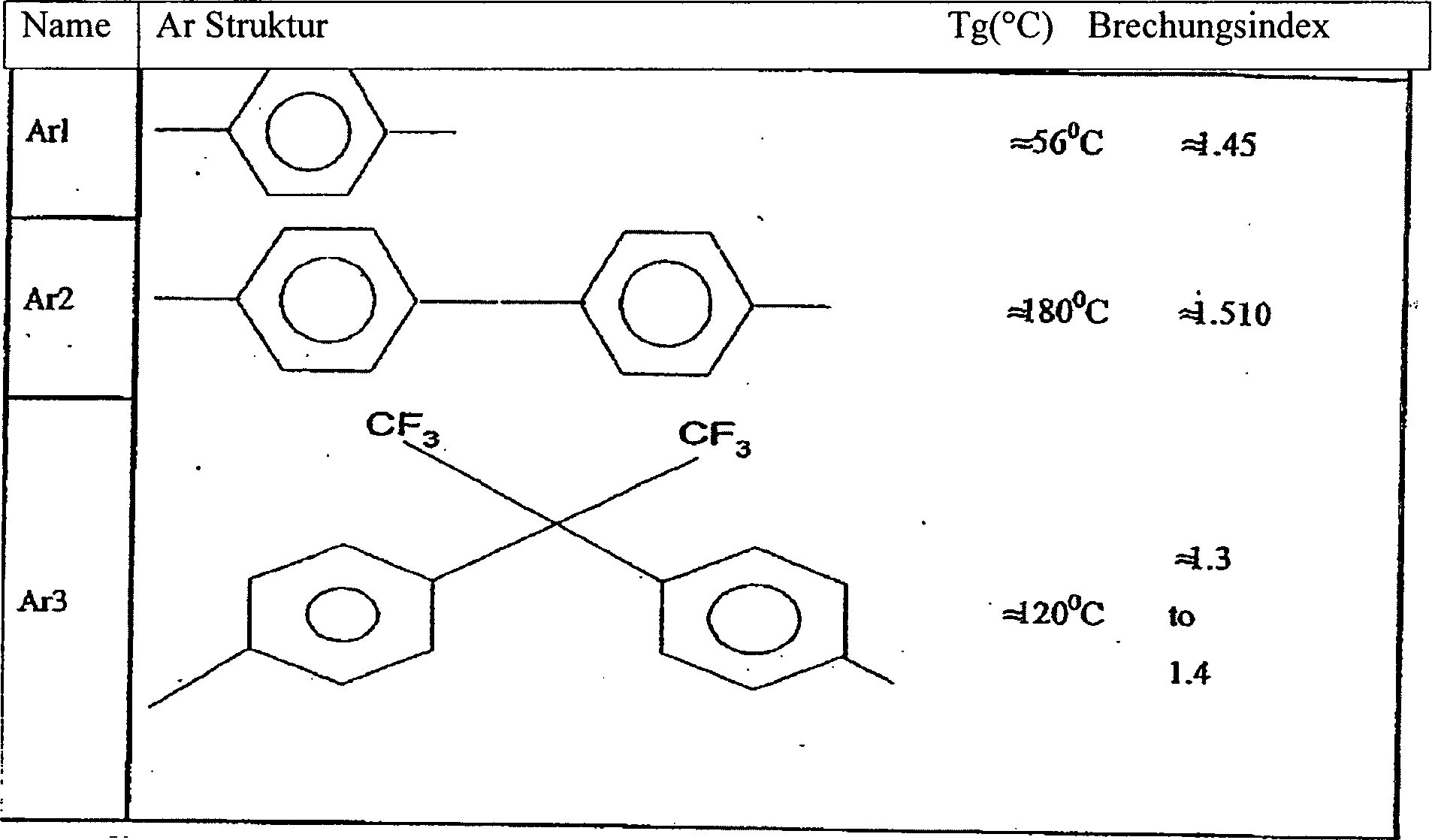
In
einer weiteren Ausführungsform
der vorliegenden Erfindung kann das Prepolymergel durch Energie aktiviert
werden, um ein verknüpftes
Polymernetzwerk zu bilden. Eine Art und Weise, auf welche dieses
erreicht werden kann, ist ein PFCB Co-Polymer zu bilden, welches
ein trifunktionales Monomer umfaßt. Ein solches Co-Polymer
hat seine Struktur, wie in
Eine
andere Klasse von Monomeren, die für die Verwendung in der Herstellung
von polymeren optischen Fasern in Übereinstimmung mit dem Gegenstand
der Erfindung geeignet ist, basiert auf Derivaten des CYTOP®-Monomers,
welches in
Eine andere Klasse von Monomeren, die für die Verwendung in der Herstellung amorpher Perfluorpolymer polymere optischer Faser geeignet sind, basiert auf Derivate des Perfluordioxol-Monomers, welches im U.S. Patent Nr. 5,498,682 beschrieben worden ist. Die Glasübergangstemperaturen und die Indices der Brechung können für die Polymere innerhalb der früher beschriebenen wünschenswerten Bereiche erhalten werden. Darüber hinaus neigt diese Klasse der Perfluordioxole nicht dazu, spontan zu homopolymerisieren und können bei Raumtemperatur nach einer herkömmlichen Destillation gehalten werden. Diese Annehmlichkeit in der Polymerherstellung passt zusammen mit den guten mechanischen Eigenschaften und der guten thermalen Stabilität der Polymere.A other class of monomers suitable for use in manufacture amorphous perfluoropolymer polymer optical fiber are suitable, based on derivatives of the perfluorodioxole monomer disclosed in U.S. Pat. Patent No. 5,498,682. The glass transition temperatures and the indices of refraction can for the Polymers within the earlier described desirable Areas can be obtained. About that In addition, this class of perfluorodioxole does not tend to spontaneously to homopolymerize and can kept at room temperature after a conventional distillation become. This convenience in polymer manufacturing fits together with the good mechanical properties and the good thermal stability of the polymers.
Eine weitere Klasse von perfluorierten Monomeren, welche amorphe Polymere und Co-Polymere bilden kann, welche in Übereinstimmung mit dem Gegenstand der Erfindung verwendet werden können, sind in der U.S. Patentanmeldung Veröffentlichungs-Nr. 20030125490 beschrieben worden. Transparente Polymere mit hohen Glasübergangstemperaturen sind beschrieben worden.A another class of perfluorinated monomers containing amorphous polymers and co-polymers can form, which in accordance can be used with the object of the invention are in U.S. Pat. Patent Application Publication No. 20030125490 has been described. Transparent polymers with high Glass transition temperatures have been described.
Eine weitere Klasse von perfluorierten Monomeren, welche amorphe Polymere und Co-Polymere bilden kann, ist in der U.S. Patentanmeldung Veröffentlichungs-Nr. 20020177667 beschrieben worden. Hochtransparente Polymere mit Glasübergangstemperaturen höher als 120°C sind beschrieben worden. Dieser Bereich der Glasübergangstemperatur ist wünschenswert, wie später beschrieben ist.A another class of perfluorinated monomers containing amorphous polymers and co-polymers is in U.S. Pat. Patent Application Publication No. 20020177667 been described. Highly transparent polymers with glass transition temperatures higher than 120 ° C are been described. This range of glass transition temperature is desirable how later is described.
Polymere mit niedrigem Molekulargewicht (3000 bis 30000 Dalton) von jedem dieser Monomere können durch die in Patenten beschriebene Verfahren, die diese Materialien beschreiben, hergestellt werden. Der Grad der Polymerisierung kann auch durch die vorher beschriebenen Verfahren des Gegenstandes der Erfindung kontrolliert werden. Post-Extrusions-Energieaktivierung kann durch eine oder mehrere der früher beschriebenen Verfahren erreicht werden und die Polymerisierung kann vervollständigt werden, wenn das Durchschnittsmolekulargewicht in dem Bereich von ungefähr 30000 bis 300000 liegt.polymers low molecular weight (3000 to 30,000 daltons) of each of these monomers can by the methods described in patents containing these materials describe be prepared. The degree of polymerization can also by the previously described methods of the subject matter of Be controlled invention. Post-extrusion energy activation can by one or more of the earlier described methods are achieved and the polymerization can be completed when the average molecular weight is in the range of approximately 30000 to 300000 lies.
Im allgemeinen werden nicht-aromatische Polymere bevorzugt, da in diesem Fall die Rayleigh-Streuung minimiert wird und die Lichtwellenleiterübertragung verbessert ist.in the In general, non-aromatic polymers are preferred because in this Case the Rayleigh scattering is minimized and the fiber optic transmission is improved.
Es würde für den Fachmann offensichtlich sein, den Vorteil der gegenständlichen Veröffentlichung zu haben, das der Gegenstand der Erfindung mit einer Vielzahl von amorphen perfluorierten Polymeren ausgeführt werden kann, welche als Kern- und Umhüllungsmaterialien dienen können.It would be for the expert be obvious, the advantage of this publication to have the subject of the invention with a variety of amorphous perfluorinated polymers can be carried out, which as Core and cladding materials can serve.
Das Beschichtungspolymer-Material, welches das optische Umhüllungsmaterial umgibt, sollte bevorzugt verschiedene Charakteristika haben. Erstens, sollte es gut an das Umhüllungspolymer adhärieren. Zweitens, ist es bevorzugt ein Beschichtungspolymer zu haben, mit einem Brechungsindex von mindestens 0,015 und noch bevorzugter von mindestens 0,03 geringer als das der Außenseite des Umhüllungspolymers. Mit diesem letzteren Unterschied im Brechungsindex erzeugt die Krümmung der Faser mit einem Krümmungsradius von 10 mm einen akzeptablen Lichtverlust von weniger als 0,5dB. In einer speziellen Ausführungsform ist die geeignete Auswahl eines Beschichtungsmaterials ein Co-Polymer von einem Monomer mit einem niedrigen Brechungsindex und mindestens 10% der Hauptmonomer-Zusammensetzung des Umhüllungspolymers. Drittens, sollte das Beschichtungspolymer bevorzugt amorph sein. Zum Abschluß sollte das Beschichtungspolymer bevorzugt perfluoriert sein. Das Beschichtungspolymer kann als Gel extrudiert werden oder als ein Polymer mit niedrigem Brechungsindex, welches aus PDD-Monomer und 10% bis 50% Monomer des Kern/Umhüllungspolymers zusammengesetzt sein kann. Das Vorhandensein des letzteren Co-Monomers kann dazu beitragen, eine gute Adhäsion an das Kern/Umhüllungsmaterial zu sichern.The Coating polymer material containing the optical cladding material should preferably have different characteristics. First, it should be good for the cladding polymer adhere. Second, it is preferred to have a coating polymer with a refractive index of at least 0.015 and more preferably of at least 0.03 lower than that of the outside of the cladding polymer. With this latter difference in the refractive index, the curvature of the Fiber with a radius of curvature of 10 mm an acceptable light loss of less than 0.5dB. In a special embodiment For example, the appropriate choice of coating material is a co-polymer of one Monomer with a low refractive index and at least 10% of the Main monomer composition of the cladding polymer. Third, should the coating polymer is preferably amorphous. At the end should the coating polymer is preferably perfluorinated. The coating polymer can be extruded as a gel or as a low polymer Refractive index, which consists of PDD monomer and 10% to 50% monomer of the core / shell polymer can be. The presence of the latter co-monomer can do so contribute a good adhesion to the core / cladding material to secure.
Das Schlauchpolymer kann eine strukturelle Stütze für die optische Faser bei Temperaturen bis mindestens 150°C, und bevorzugt mindestens 170°C und noch bevorzugter mindestens 200°C bieten. Das Material wird bevorzugt bei einer Schmelztemperatur von weniger als 270°C und noch bevorzugter weniger als 230°C extrudiert. Die Wahl des Schlauchmaterials ist bevorzugt ein hydrophobes, kristallines strukturelles Polymer, wie z.B. ein „Teflon"-ähnliches Material. Ein Beispiel ist Polyvinyliden-Fluorid (PVDF), welches ein relativ konstengünstiges und schmelzverarbeitbares Homopolymer ist. Dieses Polymer hat eine kristalline Schmelztemperatur von 171 °C und kann gute mechanische Stütze bei 150°C für eine unbegrenzte Dauer bieten. Das Polymer hat eine hohe Zugfestigkeit von 7000 lbf/in2 bei 23°C und eine gute Schlagfestigkeit. Die Wasserabsorption in dem Polymer ist sehr niedrig, 0,04%, was sehr wünschenswert ist, um den Wassertransport in die optische Faser zu minimieren. Einige relevante thermale Eigenschaften des PVDF sind in Tabelle 3 dargestellt.The tubular polymer may provide structural support for the optical fiber at temperatures up to at least 150 ° C, and preferably at least 170 ° C, and more preferably at least 200 ° C. The material is preferably extruded at a melt temperature of less than 270 ° C and more preferably less than 230 ° C. The choice of tubing is preferably a hydrophobic crystalline structural polymer, such as a "Teflon" -like material, for example, polyvinylidene fluoride (PVDF), which is a relatively inexpensive and melt-processable homopolymer.This polymer has a crystalline melting temperature of 171 And can provide good mechanical support for an indefinite period at 150 ° C. The polymer has a high tensile strength of 7000 lbf / in 2 at 23 ° C. and a good impact resistance. The water absorption in the polymer is very low, 0.04 %, which is highly desirable in order to minimize water transport into the optical fiber Some relevant thermal properties of the PVDF are shown in Table 3.
Bestimmte
Polyester können
auch erfolgreich als Schlauchpolymer verwendet werden. Die vorliegende
Erfindung kann eine Anzahl von optischen Polymeren für die Bildung
des Gradienten-Materials verwenden. Diese Materialien können im
wesentlichen unterschiedliche thermische Eigenschaften und Verarbeitungstemperaturen
haben. Ein attraktives Merkmal der Polyesterharzes sind im Bereich
der Schmelzpunkte einiger homologer Polyester (Goodman, I. And Rhys,
J.A. Polyester, Vol. 1: Saturated Polymers, Iliffe, London (1965)). Der
Schmelzpunktbereich ist von ungefähr 50°C bis ungefähr 300°C. Ein Beispiel eines Polyesters,
welches für
das Schlauchmaterial verwendet werden kann, ist Polyethylen-Terephalat (PET).
Einige relevante thermische Eigenschaften sind in Tabelle 3 gezeigt. 
Die Polyesterklasse des Polymers hat im allgemeinen gute mechanische Eigenschaften und eine geringe Wasserabsorption. Viele handelsübliche Co-Polymere und Polymermischungen sind basierend auf Esther in den Verkehr gebracht worden (Brydson, J.A. „Plastics Materials" Butterworth Scientific (1982)). Einige handelsübliche Produkte verwenden verstärkte Polyesterharze, welche auch im Gegenstand der Erfindung verwendet werden können.The Polyester class of the polymer generally has good mechanical properties Properties and low water absorption. Many commercial co-polymers and polymer blends are marketed based on Esther (Brydson, J. A. "Plastics Materials "Butterworth Scientific (1982)). Some commercial products use reinforced polyester resins, which can also be used in the subject matter of the invention.
Andere mögliche Klassen von Polymeren für die Verwendung als Schlauchmaterial umfassen HYTREL® und TEFZEL®, welche beide von duPont erhältlich sind.Other possible classes of polymer for use as tubing material include HYTREL ® and TEFZEL ®, both of which are available from duPont.
Den
Brechungsindex modifizierende Zusatzstoffe oder Dotiersubstanzen
können
in dem Kern, der Umhüllung
oder sowohl Kern als auch Umhüllungspolymeren
verwendet werden. In einer speziellen Ausführungsform kann ein Index-erhöhender Zusatzstoff
dem Kernpolymer zugefügt
werden und eine Index-erniedrigende Substanz, wenn dem Umhüllungspolymer
hinzugefügt
wird. Diese Zusatzstoffe haben bevorzugt eine oder mehrere der folgenden
Charakteristika:
Ein Molekulargewicht in dem Bereich von ungefähr 200 bis
ungefähr
3000 und bevorzugt in dem Bereich von 250 bis 1500.Refractive index modifying additives or dopants may be used in the core, cladding, or both core and cladding polymers. In a specific embodiment, an index-increasing additive may be added to the core polymer and an index-lowering substance added to the cladding polymer. These additives preferably have one or more of the following characteristics:
A molecular weight in the range of about 200 to about 3000, and preferably in the range of 250 to 1500.
Eine Löslichkeit bevorzugt bis mindestens 10 Gewichtsprozent mehr als die Konzentration, welche in dem Gegenstand der Erfindung verwendet wird. Das dient dazu, um die Tendenz zur Mikrokristallisation und/oder Phasentrennung der Zusatzstoffe in dem Polymer zu minimieren.A solubility preferably at least 10% by weight more than the concentration, which is used in the article of the invention. That serves to the tendency to microcrystallization and / or phase separation to minimize the additives in the polymer.
Eine Diffusionsfähigkeit von 10–8 bis 10–3 cm2/sek. in dem Prepolymergel oder dem Polymer bei den Verarbeitungstemperaturen dieser Erfindung.A diffusibility of 10 -8 to 10 -3 cm 2 / sec. in the prepolymer gel or polymer at the processing temperatures of this invention.
Modifizierung des Brechungsindex der Polymergrundsubstanzen des Kerns und der Umhüllung, um eine adäquat größere (≥ 0,15) numerische Apertur der Faser zu ermöglichen.modification the refractive index of the polymer base substances of the core and the wrapping to be adequate larger (≥ 0.15) numeric Aperture of the fiber to enable.
Einen geringen Dampfdruck bei den in der Erfindung verwendeten Verarbeitungstemperaturen.a low vapor pressure at the processing temperatures used in the invention.
Geeignete Zusatzstoffe für die Verwendung mit den vorher beschriebenen vollhalogenierten Polymeren umfassen vollhalogenierte Oligomere und vollhalogenierte aromatische Verbindungen. Diese Verbindungen können auch ein oder mehrere Brom- oder Jodatom(e) umfassen, um für einen hohen Brechungsindex zu sorgen. Spezielle Beispiele solcher Zusatzstoffe sind 1,3-Dibromotetrafluorbenzen und Bromoeheptafluornapthalen. Wahlweise kann eine vollhalogenierte Verbindung ein Schwefel, ein Phosphor oder andere Metallatom(e) umfassen. Bevorzugt haben die Zusatzstoffe Brechungsindices, dessen Werte sich um ≤ 0,1 von denen der Polymermatrix unterscheiden. Solche Zusatzstoffe können ausgewählt sein aus fluorierten Verbindungen oder fluorierten Verbindungen mit einem oder mehreren Chlorsubstituenten. Zusatzstoffe, um den Brechungsindex der Polymermatrix herabzusetzen, können perfluorierte Ethylen Oligomere sein. Diese Zusatzstoffe können besonders nützlich in dem Beschichtungspolymer sein.Suitable additives for use with the previously described fully halogenated polymers include fully halogenated oligomers and fully halogenated aromatic compounds. These compounds may also include one or more bromine or iodine atoms to provide a high refractive index. Specific examples of such additives are 1,3-dibromotetrafluorobenzene and bromoeheptafluoronaphthalene. Optionally, a fully halogenated compound may comprise a sulfur, a phosphor or other metal atom (s). Preferably, the additives have refractive indices whose values are ≤ 0.1 of de differ from the polymer matrix. Such additives may be selected from fluorinated compounds or fluorinated compounds having one or more chlorine substituents. Additives to lower the refractive index of the polymer matrix may be perfluorinated ethylene oligomers. These additives may be particularly useful in the coating polymer.
In einer Ausführungsform des Gegenstandes der Erfindung ist ein Index-erhöhender Zusatzstoff dem Kernpolymer hinzugesetzt worden, mit keinen anderen verwendeten Zusatzstoffen.In an embodiment the subject of the invention is an index-increasing additive to the core polymer added, with no other additives used.
In einer zweiten Ausführungsform des Gegenstandes der Erfindung ist dem Umhüllungspolymer ein Index-verringernder Zusatzstoff hinzugefügt, mit keinen anderen verwendeten Zusatzstoffen.In a second embodiment the subject of the invention is an index-reducing agent to the coating polymer Additive added, with no other additives used.
In einer dritten Ausführungsform des Gegenstandes der Erfindung ist ein Index-erhöhender Zusatzstoff dem Kernpolymer und ein Index-erniedrigender Zusatzstoff dem Umhüllungspolymer zugefügt worden, mit keinen anderen verwendeten Zusatzstoffen.In a third embodiment the subject of the invention is an index-increasing additive to the core polymer and an index-lowering additive has been added to the coating polymer, with no other additives used.
In einer vierten Ausführungsform des Gegenstandes der Erfindung ist ein Index-erhöhender Zusatzstoff dem Kern hinzugefügt worden, ein Index-erniedrigender Zusatzstoff dem Umhüllungspolymer und ein Index-erniedrigender Zusatzstoff ist dem Beschichtungspolymer hinzugefügt worden.In a fourth embodiment the subject of the invention is an index-increasing additive to the core added been an index-degrading additive to the cladding polymer and an index-lowering additive is the coating polymer added Service.
Der Gegenstand der Erfindung bezieht sich auf ein Verfahren zur Faserherstellung, welches eine Lichtdämpfung von ≤ 10db/km bei einer Wellenlänge von 850nm ermöglicht. Der Lichtverlust einer existierenden kommerziellen LUCINA-Faser ist üblicherweise 20 bis 30 dB/km beim 850nm.Of the The invention relates to a process for fiber production, which is a light attenuation of ≤ 10db / km at one wavelength of 850nm. The light loss of an existing commercial LUCINA fiber is usually 20 to 30 dB / km at 850nm.
Der Gegenstand der Erfindung bezieht sich auch auf ein Verfahren um gleichzeitig eine Faser herzustellen, deren GRIN-Profil bis 85°C stabil ist und einer optischen Dämpfung bei 850nm von ≤ 10db/km hat.Of the The invention also relates to a method simultaneously produce a fiber whose GRIN profile is stable up to 85 ° C is and an optical attenuation at 850nm of ≤ 10db / km Has.
Ein
vernünftiges
Kriterium für
die Immobilisation der Zusatzstoffe in dem Polymer ist, daß die maximale Betriebstemperatur
Top der Faser mindestens 20°C unter der
Glasuntergangstemperatur, Tgplastifiziert,
des plastifizierten Polymers sein sollte. Dies kann beschrieben
werden als:
Unterschiedliche
Zusatzstoffe können
sehr unterschiedliche Reduktionen in der Glasübergangstemperatur des reinen
Polymers hervorrufen, dessen Glasübergangstemperatur TgPolymer ist. Jedoch ist für viele Zusatzstoff/Polymer-Kombinationen
eine geeignete Charakterisierung: ![]()
![]()
Dieses
thermische Stabilitätskriterium
ist graphisch in
Die
Datenpunkte, welche der maximalen Betriebstemperatur (70°C) einer
LUCINA-Faser und die Glasübergangstemperatur
seines Grundpolymers CYTOP entsprechen, sind in
Vor
der Diskussion des optimalen Bereichs von x ist es wünschenswert,
die numerische Apertur (NA) der Faser festzusetzen. Die NA ist die
definiert als
In
einer ersten Annäherung
für jede
perfluorierte Faser
Wie
zuvor bereits angegeben, erfordert eine spezielle Ausführungsform
des Gegenstandes der Erfindung die Hinzufügung eines Index-erhöhenden Zusatzstoffes
zu dem Kernpolymer und die Hinzufügung eines Index-erniedrigenden
Zusatzstoffes zu dem Umhüllungspolymer.
Für Darstellungszwecke
sollten wir voraussetzen, daß gleiche
Zusatzstoffkonzentrationen den Kern und den Umhüllungspolymeren hinzugefügt werden. Dann
ist die Änderung
des Brechungsindexes des Polymers aufgrund des Zusatzstoffes in
dem Kern oder dem Umhüllungspolymer
0,012. Dann kann geschrieben werden:
Die
graphische Darstellung Beziehung von x und Δn ist in
Es
sollte angemerkt werden, daß die
LUCINA-Faser mit einem Index-erhöhenden
Zusatzstoff in dem Kern CYTOP-Material hergestellt worden ist und
kein Zusatzstoff in dem Umhüllungspolymer
CYTOP ist. In diesem Fall:
Es
kann in
In
Der Gegenstand der Erfindung betrifft auch ein Verfahren der Reduzierung der theoretischen LUCINA Dämpfung von 10 dB/km durch Reduzierung des Beitrags der Rayleigh Streuung von 5 dB/km.Of the The invention also relates to a method of reduction the theoretical LUCINA damping of 10 dB / km by reducing the contribution of Rayleigh scattering of 5 dB / km.
Der
Verlust von Licht durch die Rayleigh Streuung in dem CYTOP Grund-Material
und auch von dem Zusatzstoff plus Polymer in der LUCINA-Faser sind
in
Die Parameter x und Δn für die LUCINA-Faser und der Faser, die gemäß der vorliegenden Erfindung hergestellt worden ist, sind in Tabelle 4 gezeigt.The Parameters x and Δn for the LUCINA fiber and the fiber made according to the present invention are shown in Table 4.
Tabelle
4 – Vergleich
einer spezifischen Auswahl der Parameter, welche die übermäßige Rayleigh
Streuung in der LUCINA und der neuen Faser gemäß dem Gegenstand der Erfindung
kontrollieren. 
Der Wert von xΔn2 für spezifische Ausführungsformen der Faser in Übereinstimmung mit dem Gegenstand der Erfindung im Vergleich zu LUCINA kann 1/8 sein. Somit ist die überschüssige Rayleigh Streuung aus den Zusatzstoffen in den spezifischen Ausführungsformen der gegenständlichen Faser 1/8 der von der LUCINA und der typische Dämpfungsverlust von den Zusatzstoffen in dieser Ausführungsform der gegenständlichen Erfindungsfaser kann ≤ 1dB/km bei 850nm sein, oder weniger bei längeren Wellenlängen.The value of xΔn 2 for specific embodiments of the fiber in accordance with the subject invention compared to LUCINA may be 1/8. Thus, the excess Rayleigh scattering from the additives in the specific embodiments of the subject fiber is 1/8 that of the LUCINA and the typical loss of attenuation of the additives in this embodiment of the subject invention fiber may be ≤ 1dB / km at 850nm, or less at longer wavelengths ,
Die überschüssige Rayleigh
Streuung aus den Zusatzstoffen kann auch zu einer extrinsischen
Streuung von strukturellen Defekten an der Umhüllungs-/Beschichtungspolymer-Grenzfläche beitragen.
Diese strukturellen Defekte haben ein Ausmaß von 0,03 μm und sind auf Deformationen
an der Grenzfläche
zurückzuführen, die
durch die begrenzten molekularen Größen der zwei unterschiedlichen
Arten an Polymeren verursacht werden. Im Ergebnis schwankt der Brechungsindex
auf der obigen Skala. Das vorhandene Verfahren der Herstellung von
Gradientenindexfaser LUCINA bietet ein Profil ähnlich dem der in
Die Kalkulation hat gezeigt, daß die erste der beiden obigen Mechanismen teilweise wichtig ist für Modi höherer Ordnung der Lichtdurchlässigkeit in der Faser. Im Ergebnis tritt eine unterschiedliche Verminderung der Modi ein und trägt signifikant zu der gemessenen Lichtdämpfung, wie zuvor beschrieben, bei.The Calculation has shown that the First of the above two mechanisms is sometimes important for higher order modes the translucency in the fiber. As a result, a different reduction of the Modes and carries significant to the measured light attenuation, as previously described, at.
Der
Gegenstand der Erfindung bezieht sich auch auf ein Verfahren, um
diesen extrinsischen Verlust an Licht zu umgehen. In einer spezifischen
Ausführungsform
kann der Gegenstand der Erfindung die Stufenindex Umhüllungs-/Beschichtungsgrenzfläche reduzieren
oder eliminieren. Solche eine Reduktion oder Elimination der Stufenindex
Umhüllungs-Beschichtungsgrenzfläche kann
durch die Herstellung eines Profils erreicht werden, wie zum Beispiel
gezeigt in
Drei
Ausführungsformen
dieser Erfindung sind zuvor beschrieben worden, in denen Zusatzstoffe
hinzugefügt
worden sind:
Nur dem Kern.
Nur der Umhüllung.
Sowohl zu den Kern
als auch zu den Umhüllungsmaterialien.Three embodiments of this invention have been previously described in which additives have been added:
Only the core.
Only the serving.
Both to the core and to the wrapping materials.
Die Ausführungsform, die Zusatzstoffe sowohl im Kern als auch in den Umhüllungsmaterialien umfaßt, kann für das Erreichen hoher thermaler Stabilität (85°C) und guter Lichtwellenleiterübertragung bevorzugt sein.The embodiment, the additives in both the core and the wrapping materials can, can for the Achieving high thermal stability (85 ° C) and good optical fiber transmission be preferred.
Eine
schematische Darstellung des radialen Profils der Faser gleich nach
der Extrusion für
eine Ausführungsform,
in welcher Zusatzstoffe nur dem Kern hinzugefügt worden sind, ist in
In
einer weiteren Ausführungsform
des Gegenstandes der Erfindung ist ein Indexerniedrigender Zusatzstoff
dem Beschichtungspolymer hinzugefügt worden, zusätzlich zu
den Zusatzstoffen, die dem Kern- und dem Umhüllungsmaterial hinzugefügt worden
sind. Eine schematische Darstellung des radialen Profils der Faser
für diese
Ausführungsform
ist sofort nach der Extrusion in der
Für ein vorgegebenes perfluoriertes Polymeres Grundmaterial für den Kern und das Umhüllungsmaterial und die Auswahl von Zusatzstoffen, ausgewählt wie zuvor diskutiert, ist es möglich folgende Verfahrensvariablen zu wählen, um ein optimales Brechungsindexprofil zu erreichen:
- 1) Die Durchflussraten von (i) dem Kernextruder E-1 (ii) dem Umhüllungsextruder E-2 (iii) dem Beschichtungsextruder E-3
- 2) Die Diffusionsfähigkeit der Zusatzstoffe in den Kern-, den Umhüllungs- und den Beschichtungspolymeren.
- 3) Der Temperatur des Ofens, innerhalb welchem die Diffusion erfolgt.
- 4) Das Zeitintervall, das die Faser in dem Ofen verbleibt.
- 1) The flow rates of (i) the core extruder E-1 (ii) the cladding extruder E-2 (iii) the coating extruder E-3
- 2) The diffusibility of the additives in the core, clad and coating polymers.
- 3) The temperature of the furnace inside which the diffusion takes place.
- 4) The time interval that the fiber remains in the oven.
Eine begrenzte Elementanalyse unter Verwendung der obigen Parameter kann verwendet werden, um das endgültige Brechungsindexprofil vorauszusagen. Auf diese Art und Weise kann das Verfahren abgestimmt werden, um das gewünschte Profil für eine maximale Übertragungsbandbreite zu erzielen. Dieses Verfahren vermeidet das Erfordernis für einen umfangreichen Versuch und Irrtum mit den Materialien und den Verfahrensbedingungen. Diese Art der Analyse ist für den Fall eines einzelnen Zusatzstoffes und eines Kern-/Umhüllungs Coextrusions-System (Blyler, L. et al. US Patent Nr. 6,254,808) beschrieben worden. Jedoch ist es einfacher, die Analyse auf die gewünschte Konfiguration des Gegenstandes der Erfindung auszuweiten.A limited elemental analysis using the above parameters can used to be the final one Predict refractive index profile. In this way you can The method can be tuned to the desired profile for a maximum transmission bandwidth to achieve. This method avoids the need for one extensive trial and error with the materials and process conditions. This type of analysis is for the case of a single additive and a core / cladding coextrusion system (Blyler, L. et al., U.S. Patent No. 6,254,808). However, it is easier to analyze the desired configuration of the object expand the invention.
Der Gegenstand der Erfindung bezieht sich auch auf ein Verfahren für den Erhalt einer niedrigen Lichtdämpfung, in welcher das gegenständliche Verfahren das Ausglühen von thermisch oder mechanisch induzierten Spannungsschwankungen in dem optischen Material umfaßt, wie vorher in der Beschreibung des Faserherstellungsprozesses beschrieben.Of the The invention also relates to a method for obtaining a low light attenuation, in which the figurative Process the annealing of thermally or mechanically induced voltage fluctuations in the optical material comprises as previously described in the description of the fiber manufacturing process.
Die
Faser, die gemäß der speziellen
Ausführungsformen
des gegenständlichen
Verfahrens hergestellt worden ist, können eine Lichtdämpfung versus
der Wellenlänge
haben, wie in 
Diese Übertragungsbanden stimmen sehr gut mit der Verwendung des Grobe Wellenlängenmultiplex (Course Wavelength Division Multiplexing (CWDM)) überein. Eine übliche Trennung zwischen einzelnen Übertragungswellenlängen ist 20 nm in CWDM. Somit kann eine Gesamtmenge von mindestens 16 und möglicherweise 20 einzelnen Übertragungswellenlängen für eine gegebene Faser verwendet werden.These transmission bands Coordinate very well with the use of the Coarse Wavelength Division Multiplex (Course Wavelength Division Multiplexing (CWDM)). A usual separation between individual transmission wavelengths 20 nm in CWDM. Thus, a total of at least 16 and possibly 20 single transmission wavelengths for a given Fiber can be used.
Die X-Bande paßt sehr gut mit der Verwendung des Vertical Cavity Surface Emitting Lasers (VCSELs) zusammen, welcher bei 850nm arbeitet. Die Dämpfung dieser Bande ist adäquat für die Verwendung in Local Area Networks (LAN), Storage Area Networks (SAN) und Zentralstellen.The X-band fits very good with the use of Vertical Cavity Surface Emitting Lasers (VCSELs) working at 850nm. The damping of this Gang is adequate for use in local area networks (LANs), storage area networks (SANs) and central offices.
Die Y-Bande hat die höchste Lichtwellenleiterübertragung. Diese Bande paßt sehr gut zu der Verwendung von VCSELs mit der Faser über eine Distanz bis zu drei Kilometern.The Y-band has the highest Fiber optic transmission. This gang fits very good at using VCSELs with the fiber over one Distance up to three kilometers.
Die Z-Bande kann auch für die Fernübertragung und Verwendung des VCSEL-Transmitters verwendet werden.The Z gang can also for the remote transmission and using the VCSEL transmitter.
In
einer besonderen Ausführungsform
kann eine Gradientenindexfaser mit einer optischen Absorption ≤ 10dB/km in
dem Bereich 760-1250 nm unter Verwendung der folgenden Materialien
und Lehren hergestellt werden:
Die Glasübergangstemperatur des für den Kern
und die Umhüllung
verwendeten Polymers sollte ≥ 120°C sein, bevorzugt ≥ 130°C und noch
bevorzugter ≥ 140°C.In a particular embodiment, a graded index fiber with an optical absorption ≤ 10dB / km in the range 760-1250 nm can be made using the following materials and teachings:
The glass transition temperature of the polymer used for the core and the cladding should be ≥ 120 ° C, preferably ≥ 130 ° C, and more preferably ≥ 140 ° C.
Ein den Brechungsindex erhöhender Zusatzstoff in dem Kernpolymer mit einer Konzentration ≥ 10%wdwt und noch bevorzugter ≥ 20%. Der Zusatzstoff sollte entsprechende Unterschiede des Brechungsindex bei dem Polymer von < 0,1 haben, und noch bevorzugter ≤ 0,05 haben. Ein den Brechungsindex verringernder Zusatzstoff in dem Umhüllungspolymer mit ähnlichen Konzentrationen und negativen Unterschieden des Brechungsindex relativ zu dem Umhüllungspolymer.One increasing the refractive index Additive in the core polymer with a concentration ≥ 10% wdwt and even more preferably ≥ 20%. The additive should have corresponding differences in the refractive index in the polymer of <0.1 and more preferably ≤ 0.05 to have. An index-reducing additive in the cladding polymer with similar ones Concentrations and negative differences of the refractive index relative to the coating polymer.
Ein den Brechungsindex verringernder Zusatzstoff in dem Beschichtungspolymer. Der Brechungsindex des Zusatzstoffes kann vergleichbar mit dem Beschichtungspolymers sein. Das Brechungsindexprofil sollte so hergestellt werden, daß es sich kontinuierlich vom Kern zum Beschichtungspolymer in radialen Regionen verändert.One refractive index reducing additive in the coating polymer. The refractive index of the additive may be comparable to the coating polymer be. The refractive index profile should be made to be continuously changed from core to coating polymer in radial regions.
Das Herstellungsverfahren sollte wirksam thermisch oder mechanisch induzierte Spannungen in der Faser ausglühen.The Manufacturing process should be effective thermally or mechanically induced Anneal stresses in the fiber.
Eine weitere Ausführungsform des Gegenstandes der Erfindung bezieht sich auf ein Verfahren zur Herstellung einer Faser mit dem Produkt aus Bandbreite und Wegstrecke von 10Gbps·300 Meter. Wie in der Beschreibung des Standes der Technik behandelt, hat die LUCINA-Faser ein Brechungsindexprofil, welches erheblich von dem gewünschten parabelförmigen Verhalten bei einem großen Radius abweicht. Dieses Profil mit seiner schwachen Annäherung an eine Parabel führt zu einem Faktor dreimal kleiner als das Produkt aus Bandbreite und Wegstrecke. Es ist eine Aufgabe dieser Erfindung, ein Verfahren zur Faserherstellung zu lehren, welches ein beinahe parabelförmiges Brechungsindexprofil hat und das gewünschte Produkt aus der Bandbreite und Wegstrecke von 10Gpbs·300m.A another embodiment The subject matter of the invention relates to a process for the preparation a fiber with the product of bandwidth and range of 10Gbps · 300 meters. As discussed in the description of the prior art, the LUCINA fiber has a refractive index profile significantly different from that desired parabolic Behavior in a big one Radius deviates. This profile with its weak approach a parable leads to a factor three times smaller than the product of bandwidth and Distance. It is an object of this invention to provide a method to teach fiber production, which has a nearly parabolic refractive index profile has and the desired Product of the bandwidth and range of 10Gpbs · 300m.
Das
Brechungsindexprofil kann durch das herkömmliche Potenzgesetz geschätzt werden. 
r
ist ein beliebiger Wert des Radius, r2 ist
der äußere Wert
des Umhüllungsradius,
wie in
r is any value of the radius, r 2 is the outer value of the envelope radius, as in
Ishigure,
T. et al. (2001) haben den Bestwert von g (ungefähr 2,2) bestimmt und die dazugehörige Übertragungsbandbreite
unter Berücksichtung
sowohl der modalen Dispersion als auch der Materialdispersion. Eine
VCSEL mit einer 1,0nm spektralen Breite ist in der Berechnung angenommen
worden. Das Ergebnis der Berechnung ist in
Der
Gegenstand der Erfindung bezieht sich auch auf ein Verfahren zur
Faserherstellung, Charakteristika sind folgende:
Die Optische
Absorption ≤ 10dB/km
in dem Wellenlängenbereich
760 nm bis 1250 nm.The subject of the invention also relates to a process for fiber production, characteristics are as follows:
The optical absorption ≤ 10dB / km in the wavelength range 760 nm to 1250 nm.
Das Produkt aus Bandbreite·Distanz ist gleich 10Gbps·300 Meter oder entsprechend 3Gbps·1000 Meter.The Product of bandwidth · distance is equal to 10Gbps · 300 Meters or according to 3Gbps · 1000 Meter.
Eine Faser, welche mit einem Radius über eine Krümmung von 10mm mit weniger als 0,5db Verlust gebogen werden kann.A Fiber, which has a radius over a curvature of 10mm with less than 0.5db loss can be bent.
In
einer speziellen Ausführungsform
des Gegenstandes der Erfindung können
ummantelte Simplexkabel hergestellt werden.
In
einer noch weiteren Ausführungsform
des Gegenstandes der Erfindung kann die Pressform D in
Eine
andere Ausführungsform
des Gegenstandes der Erfindung bezieht sich auf die Herstellung
eines Duplexkabels, wie in
Eine Ausführungsform der Erfindung ist die gleichzeitige Herstellung von mehreren Duplexkabeln in einer ähnlichen Art und Weise wie der, wie sie für mehrere Simplexkabel beschrieben worden ist. Eine entsprechende Erhöhung der Produktionsrate der Duplexkabel kann erreicht werden.A embodiment The invention is the simultaneous production of multiple duplex cables in a similar Way like the one for several simplex cables have been described. A corresponding increase The production rate of duplex cables can be achieved.
In
einer weiteren Ausführungsform
der Erfindung kann ein Flachbandkabel von mehreren POF hergestellt
werden.
In einer weiteren Ausführungsform der Erfindung kann ein zweidimensionales Array von POF hergestellt werden.In a further embodiment In accordance with the invention, a two-dimensional array of POF can be made become.
Der Gegenstand der Erfindung ist zur Herstellung einer Gradientenindex polymeren optischen Faser aus einer Vielzahl von Materialien mit einer Auswahl von Durchmessern und Brechungsindexprofilen geeignet. Das Produkt der Erfindung kann in Form von Simplex, Duplex und/oder Flachbandkabeln sein.Of the The invention relates to the production of a gradient index polymeric optical fiber of a variety of materials with a choice of diameters and refractive index profiles. The Product of the invention may be in the form of simplex, duplex and / or Be ribbon cables.
Der Gegenstand der Erfindung betrifft die Herstellung eines optischen polymeren Kabels mit einzigartigen Spezifikationen. Diese Spezifikationen ermöglichen zum ersten Mal die wirtschaftliche Verwendung der optischen Faser zur Wohnstätte (FTTM) über die „letzte Meile".Of the The invention relates to the production of an optical polymeric cable with unique specifications. These specifications enable for the first time the economical use of the optical fiber to the dwelling place (FTTM) via the last Mile".
Das Telekommunikationsgesetz von 1996 eröffnete den Wettbewerb für die Zustellung von Datenübertragungsverbindungen in der „letzten Meile".The Telecommunications Act of 1996 opened the competition for service of data transmission connections in the last Mile".
Telefonfirmen und Kabelfernsehbetreiber installieren unabhängig Glas „Fasern zu der Nachbarschaft". Diese Glasfaser wird begrenzt an dem fernen Knotenpunkt ,Remote Node' in der Nachbarschaft. Die Nachbarschaft ist in diesem Zusammenhang definiert als die Region, welche alle Wohnhäuseranordnungen innerhalb eines Radius von ungefähr einer Meile umfaßt. Bis zu der Entwicklung der < 10 dB/km Polymerfaser dieser Erfindung war es nicht möglich, Polymere eher als Glasfasern für die Verwendung in dieser „letzten Meile" in Betracht zu ziehen. Die letzte Meile zu den Wohnstätten ist mit oder wird mit Kupferkabeln und/oder koaxialen Kupferkabeln verbunden, aber dort gibt es aufgrund der Kosten nur eine geringe Verwendung von Glasfasern. Die Faser, die durch den Gegenstand der Erfindung ermöglicht wurde, kann eine geringe optische Dämpfung haben und eine hohe Bandbreite und weitläufig einsetzbar. Das gegenständliche Kabel kann eine einfache Installierung bieten, eine kostengünstige Alternative zu den bestehenden Kupferlösungen der Kabel und koaxialen Kabeln.telephone companies and cable TV operators independently install glass "fibers to the neighborhood." This fiber is bounded at the remote node 'remote node' in the neighborhood. The neighborhood is defined in this context as the region, which all residential house arrangements within a radius of about a mile. Up to the development of <10 dB / km polymer fiber of this invention, it was not possible to use polymers rather than glass fibers for the use in this "last Mile " to draw. The last mile to the dwelling is with or with Copper cables and / or coaxial copper cables connected, but there Due to the cost, there is little use of glass fibers. The Fiber made possible by the subject invention can have a low optical attenuation and a high bandwidth and widely used. The objective Cable can provide easy installation, a cost effective alternative to the existing copper solutions cables and coaxial cables.
Es
gibt zumindest drei unterschiedliche Architekturen, welche für die Inbetriebnahme
von Glasfasern in der letzten Meile diskutiert worden sind, oder
entsprechend in der Verteilerkreis. Schematische Darstellungen dieser
drei Architekturen sind in den
Die
Verfügbarkeit
der Faser, die in Übereinstimmung
mit dem Gegenstand der Erfindung hergestellt wurde, ermöglicht seine
Verwendung in den Verteilerkreis, die in
In
dem wichtigen Fall des Einsatzes von FTTH in dem städtischen
Umfeld ist die Einfachheit und die geringen Kosten der Erschliessung
von entscheidender Bedeutung, da sich die Anzahl der Anschlüsse dramatisch
erhöht.
Eine schematische Darstellung eines möglichen WDM PON Verteilerkreises
in der städtischen Umgebung
ist in
In einer noch anderen Ausführungsform der gegenständlichen städtischen Verwendung des gegenständlichen Kabels kann eine Schaltung, die ein WDM PON nutzt, wie in Figur 24 gezeigt, verwendet werden. Jedoch überträgt in diesem Fall die geteilte Zuleitung (feeder line) die Gigabit Ethernet bei jeder Wellenlänge. Der ferne Knotenpunkt sorgt für ein Gigabit Ethernet bei jeder übertragenen Wellenlänge über jedes der polymeren optischen Kabel in der Verteilerkreis (Distribution Loop). Im Kommunikationsraum des Multiwohnstättengebäudes kann eine Faser an einen Schalter geschlossen werden, welcher 10 oder mehr 100 Mbps Ports liefert, jedes von denen kann einzeln an ein Appartement angeschlossen werden. Wahlweise kann eine höhere Bedienungsqualität von 1Gbps direkt an das Appartement angeschlossen werden.In a still other embodiment the figurative urban Use of the subject Cable can be a circuit that uses a WDM PON, as shown in FIG 24 can be used. However in this case transfers the split Feeder line the Gigabit Ethernet at any wavelength. Of the distant node provides for a Gigabit Ethernet at each transmitted Wavelength over each the polymeric optical cable in the distribution circuit (distribution Loop). In the communication room of the multi-dwelling building a fiber can be connected to one Switch that delivers 10 or more 100 Mbps ports, each of them can be connected individually to an apartment. Optionally, a higher operating quality of 1Gbps be connected directly to the apartment.
In
einer weiteren Ausführungsform
des Gegenstandes der Erfindung kann eine Schaltung für einen Heimarbeitsplatz
(Home Run Architecture), wie in
Es
kann der
Es ist offensichtlich für jeden Fachmann, daß der Vorteil des neuen Herstellungsverfahrens einer spezifischen Ausführungsform des Gegenstandes der Erfindung ein polymeres optisches Kabel mit den folgenden Charakteristika zur Verfügung stellen kann.It is obvious for every professional that the Advantage of the new manufacturing method of a specific embodiment the subject invention of a polymeric optical cable with can provide the following characteristics.
Eine
geringe Dämpfung,
die eine Übertragung über Distanzen
von einigen wenigen Kilometern ermöglicht,
eine Erleichterung
des Trennens und geringe Kosten von verbindenden Teilen und Transceivern,
einige Übertragungsfenster
innerhalb jedes von denen grobe Wellenlängenmultiplex (CWDM, Coarse
wavelengths division multiplexing) verwendet werden kann, es bietet
einen neuen Ansatz an, um die Versprechungen des Telekommunikationsgesetz
von 1996 bezüglich
der Verringerung der Kommunikationskosten für die Verbraucher zu senken
zu erfüllen,
es
bietet ein kostengünstiges
Duplexkabel mit der Einfachheit des Trennens für Local Area Networks und Storage
Area Networks.A low attenuation, which allows transmission over distances of a few kilometers,
a facilitation of separation and low cost of connecting parts and transceivers,
Some transmission windows within each of which coarse wavelengths division multiplexing (CWDM) can be used, it offers a new approach to meet the promises of the Telecommunications Act of 1996 to reduce communication costs for consumers,
It offers a cost-effective duplex cable with the ease of disconnection for Local Area Networks and Storage Area Networks.
Diese und andere Änderungen und Abweichungen der vorliegenden Erfindung können durch den Fachmann ausgeführt werden, ohne sich von dem Geist und dem Umfang der vorliegenden Erfindung zu entfernen. Darüber hinaus sollte verstanden werden, daß Aspekte der verschiedenen Ausführungsformen entweder im Ganzen oder teilweise ausgetauscht werden können. Des Weiteren werden jene auf dem Fachgebiet anerkennen, daß die vorangegangene Beschreibung nur als Beispiel dient und nicht beabsichtigt ist, die Erfindung, wie hierin beschrieben, einzuschränken.These and other changes and variations of the present invention may be made by those skilled in the art, without departing from the spirit and scope of the present invention to remove. About that addition, it should be understood that aspects of the various embodiments either in whole or in part can be exchanged. Of Further, those in the art will recognize that the preceding Description is only an example and not intended to limit the invention as described herein.
Alle Patente, Patentanmeldungen, Provisional Anmeldungen und Veröffentlichungen, auf die hierin Bezug genommen wird oder die hierin zitiert werden, sind durch die Bezugnahme in ihrer Gesamtheit aufgenommen, einschließlich aller ihrer Figuren und Tabellen, in dem Umfang, in dem sie nicht im Widerspruch zu den ausdrücklichen Lehren dieser Beschreibung stehen.All Patents, patent applications, provisional applications and publications, to which reference is made herein or cited herein are incorporated by reference in their entirety, including all their figures and tables, to the extent that they do not conflict to the express Teachings of this description stand.
Claims (59)
Applications Claiming Priority (3)
| Application Number | Priority Date | Filing Date | Title |
|---|---|---|---|
| US44636903P | 2003-02-10 | 2003-02-10 | |
| US446369P | 2003-02-10 | ||
| PCT/US2004/003764 WO2004072697A1 (en) | 2003-02-10 | 2004-02-10 | Method and apparatus for manufacturing plastic optical transmission medium |
Publications (2)
| Publication Number | Publication Date |
|---|---|
| DE602004003342D1 DE602004003342D1 (en) | 2007-01-04 |
| DE602004003342T2 true DE602004003342T2 (en) | 2007-06-14 |
Family
ID=32869498
Family Applications (1)
| Application Number | Title | Priority Date | Filing Date |
|---|---|---|---|
| DE602004003342T Expired - Fee Related DE602004003342T2 (en) | 2003-02-10 | 2004-02-10 | METHOD AND APPARATUS FOR THE MANUFACTURE OF OPTICAL TRANSMISSION MEDIA |
Country Status (6)
| Country | Link |
|---|---|
| US (1) | US20050062181A1 (en) |
| EP (1) | EP1592991B1 (en) |
| CN (1) | CN1771443A (en) |
| AT (1) | ATE346316T1 (en) |
| DE (1) | DE602004003342T2 (en) |
| WO (1) | WO2004072697A1 (en) |
Families Citing this family (19)
| Publication number | Priority date | Publication date | Assignee | Title |
|---|---|---|---|---|
| WO2005028193A1 (en) * | 2003-09-15 | 2005-03-31 | Nanoptics, Incorporated | Method of manufacturing multi-polymer optical fiber cable |
| US20080061457A1 (en) * | 2004-09-09 | 2008-03-13 | Nanoptics, Incorporated | Manufacturing Method of Acrylic Optical Fiber with Improved Environmental Stability |
| JP2006208551A (en) * | 2005-01-26 | 2006-08-10 | Fuji Photo Film Co Ltd | Method and equipment for manufacturing plastic optical fiber |
| US20090220785A1 (en) * | 2005-10-12 | 2009-09-03 | Adelaide Research & Innovation Pty Ltd | Method and device for forming microstructured fibre |
| US7539381B2 (en) * | 2007-05-11 | 2009-05-26 | Corning Incorporated | Low bend loss coated optical fiber |
| EP2215030A1 (en) * | 2007-11-06 | 2010-08-11 | Prysmian S.p.A. | Process for manufacturing an optical fiber and an optical fiber so obtained |
| NL1035403C2 (en) * | 2008-05-08 | 2009-11-11 | Draka Comteq Bv | Data communication cable. |
| FR2938389B1 (en) * | 2008-11-07 | 2011-04-15 | Draka Comteq France | MULTIMODE OPTICAL SYSTEM |
| US9739962B2 (en) * | 2013-05-14 | 2017-08-22 | Vixar | Plastic optical fiber data communication links |
| JP2015203710A (en) * | 2014-04-10 | 2015-11-16 | 株式会社ダイセル | polymer optical fiber |
| JP6446822B2 (en) * | 2014-04-24 | 2019-01-09 | 三菱ケミカル株式会社 | Optical fiber manufacturing method, optical fiber, communication device, and illumination |
| JP6640529B2 (en) * | 2015-10-30 | 2020-02-05 | 株式会社クラベ | Optical transmission body and method of manufacturing the same |
| JP2019049658A (en) * | 2017-09-11 | 2019-03-28 | 小池 康博 | Optical fiber cable |
| CN107561634B (en) * | 2017-09-12 | 2023-06-20 | 厦门华方软件科技有限公司 | Polymer optical fiber for ultra-high speed communication and preparation method thereof |
| US10998976B2 (en) | 2019-08-26 | 2021-05-04 | The Boeing Company | Process for extending operating temperature range of gigabit plastic optical fiber |
| WO2022176864A1 (en) * | 2021-02-16 | 2022-08-25 | 日東電工株式会社 | Plastic optical fiber and manufacturing method thereof |
| WO2022209921A1 (en) * | 2021-03-31 | 2022-10-06 | 日東電工株式会社 | Plastic optical fiber and manufacturing method thereof |
| WO2023054141A1 (en) * | 2021-09-30 | 2023-04-06 | 日東電工株式会社 | Plastic optical fiber and method for manufacturing same |
| WO2023190794A1 (en) * | 2022-03-31 | 2023-10-05 | 日東電工株式会社 | Plastic optical fiber |
Family Cites Families (28)
| Publication number | Priority date | Publication date | Assignee | Title |
|---|---|---|---|---|
| US4587065A (en) * | 1983-07-02 | 1986-05-06 | Nippon Sheet Glass Co., Ltd. | Method for producing light transmitting article of synthetic resin |
| GB8627916D0 (en) * | 1986-11-21 | 1986-12-31 | Bonar Carelle Ltd | Absorbent products |
| JP3471015B2 (en) * | 1992-08-17 | 2003-11-25 | 康博 小池 | Method for manufacturing plastic optical transmission body |
| EP0585533B1 (en) * | 1992-08-19 | 1998-08-05 | Sumitomo Electric Industries, Limited | Mode field diameter conversion fiber |
| WO1994029758A1 (en) * | 1993-06-16 | 1994-12-22 | Sumitomo Electric Industries, Ltd. | Plastic optical fiber base material, production method therefor, and apparatus therefor |
| IT1264662B1 (en) * | 1993-07-05 | 1996-10-04 | Ausimont Spa | PERFLURODIOSSOLS THEIR HOMOPOLYMERS AND COPOLYMERS AND THEIR USE FOR THE COATING OF ELECTRIC CABLES |
| US5508359A (en) * | 1993-11-22 | 1996-04-16 | The Dow Chemical Company | Blends of high MW branched polycarbonate with a lower MW polycarbonate |
| EP1249715A3 (en) * | 1994-04-18 | 2003-01-02 | Yasuhiro Koike | Graded-refractive-index optical plastic material and method for its production |
| US5760139A (en) * | 1994-04-18 | 1998-06-02 | Yasuhiro Koike | Graded-refractive-index optical plastic material and method for its production |
| US5555525A (en) * | 1994-09-07 | 1996-09-10 | Industrial Technology Research Institute | Method of making graded refractive index polymeric optical fibers and optical fibers made by the method |
| US5616638A (en) * | 1995-03-20 | 1997-04-01 | Rohm And Haas Company | Cured composite and process therefor |
| DE69614023T2 (en) * | 1995-04-20 | 2002-03-21 | At & T Corp | Process for quickly applying and curing an optical fiber coating |
| US6106745A (en) * | 1995-11-30 | 2000-08-22 | Akzo Nobel Nv | Method of making graded index polymeric optical fibers |
| ATE431566T1 (en) * | 1996-03-28 | 2009-05-15 | Mitsubishi Rayon Co | OPTICAL FIBER WITH DISTRIBUTED REFRACTIVE INDEX AND METHOD FOR THE PRODUCTION THEREOF |
| JPH10253840A (en) * | 1997-03-07 | 1998-09-25 | Sumitomo Wiring Syst Ltd | Manufacture of refractive index distribution type plastic optical fiber and manufacturing device therefor |
| US6368533B1 (en) * | 1997-12-22 | 2002-04-09 | Kimberly-Clark Worldwide, Inc. | Process for forming films, fibers and base webs from thermoset polymers |
| FR2784196B1 (en) * | 1998-10-01 | 2000-12-15 | Cit Alcatel | INDEX GRADIENT PLASTIC OPTICAL FIBER AND CONTINUOUSLY MANUFACTURING INDEX GRADIENT PLASTIC OPTICAL FIBER |
| JP3387061B2 (en) * | 1999-03-24 | 2003-03-17 | サムソン・エレクトロニクス・カンパニー・リミテッド | Substance whose properties change in the radial direction, apparatus for preparing the same, and method for preparing the same |
| US6242548B1 (en) * | 1999-05-13 | 2001-06-05 | Dyneon Llc | Fluoroplastic polymers with improved characteristics |
| US6277919B1 (en) * | 1999-05-13 | 2001-08-21 | Dyneon Llc | Polymer processing additive containing a multimodal fluoropolymer and melt processable thermoplastic polymer composition employing the same |
| US6254808B1 (en) * | 1999-05-27 | 2001-07-03 | Lucent Technologies Inc. | Process for fabricating plastic optical fiber |
| FR2795997B1 (en) * | 1999-07-05 | 2001-10-19 | Cit Alcatel | METHOD FOR MANUFACTURING AN INDEX GRADIENT PLASTIC OPTICAL FIBER |
| US6265018B1 (en) * | 1999-08-31 | 2001-07-24 | Lucent Technologies Inc. | Fabricating graded index plastic optical fibers |
| KR100368692B1 (en) * | 2000-03-21 | 2003-01-24 | 옵티미디아(주) | Rod type polymer preform having radially-varying properties, process for the preparation thereof and apparatus therefor |
| EP1272336A2 (en) * | 2000-04-12 | 2003-01-08 | Nanoptics, Inc. | Method and apparatus for manufacturing plastic optical transmission medium |
| AU2001260645A1 (en) * | 2000-05-31 | 2001-12-11 | Asahi Glass Company, Limited | Novel fluorine compound, process for producing the same, and polymer thereof |
| US6527986B2 (en) * | 2001-02-07 | 2003-03-04 | Fitel Usa Corp. | Extrusion process for fabricating plastic optical fiber |
| EP1256592B1 (en) * | 2001-05-07 | 2007-07-11 | Solvay Solexis S.p.A. | Amorphous perfluorinated copolymers |
-
2004
- 2004-02-10 US US10/775,567 patent/US20050062181A1/en not_active Abandoned
- 2004-02-10 AT AT04709854T patent/ATE346316T1/en not_active IP Right Cessation
- 2004-02-10 EP EP04709854A patent/EP1592991B1/en not_active Expired - Lifetime
- 2004-02-10 WO PCT/US2004/003764 patent/WO2004072697A1/en active IP Right Grant
- 2004-02-10 DE DE602004003342T patent/DE602004003342T2/en not_active Expired - Fee Related
- 2004-02-10 CN CN200480009660.0A patent/CN1771443A/en active Pending
Also Published As
| Publication number | Publication date |
|---|---|
| ATE346316T1 (en) | 2006-12-15 |
| EP1592991A1 (en) | 2005-11-09 |
| DE602004003342D1 (en) | 2007-01-04 |
| CN1771443A (en) | 2006-05-10 |
| US20050062181A1 (en) | 2005-03-24 |
| EP1592991B1 (en) | 2006-11-22 |
| WO2004072697A1 (en) | 2004-08-26 |
Similar Documents
| Publication | Publication Date | Title |
|---|---|---|
| DE602004003342T2 (en) | METHOD AND APPARATUS FOR THE MANUFACTURE OF OPTICAL TRANSMISSION MEDIA | |
| DE60131323T2 (en) | Plastic optical fiber | |
| DE2528991A1 (en) | ELEMENT OF UN DETERMINED LENGTH WITH OPTICAL FIBER | |
| DE69832355T2 (en) | METHOD FOR PRODUCING AN OPTICAL FIBER WITH DISTRIBUTED BREAKING INDEX | |
| DE60301096T2 (en) | Optical fibers with buffer layer and associated manufacturing method | |
| DE69838554T2 (en) | Optical fiber with gradient index | |
| US7135133B2 (en) | Method and apparatus for manufacturing plastic optical transmission medium | |
| DE60124113T2 (en) | PLASTIC LIGHTING WAVE, LIGHT WAVE CABLE AND OPTICAL TRANSMISSION DEVICE | |
| CA1321720C (en) | Optical waveguide | |
| DE3625180C2 (en) | ||
| DE2921338C2 (en) | Optical fiber for use in optical communications | |
| EP0315874B1 (en) | Method for manufacturing an optical coupler for polymer light guides | |
| KR0180517B1 (en) | Light guide | |
| DE60201386T2 (en) | Optical plastic fiber and process for its production | |
| DE3319536C1 (en) | Plastic optical fiber | |
| DE102013009169B4 (en) | Method of melt spinning a fiber varying over its cross section and its use | |
| JP2004177954A (en) | Preform of plastic optical fiber | |
| US20030132536A1 (en) | Method of making a graded index polymer optical fiber | |
| JP3719734B2 (en) | Plastic optical fiber cord and bundle fiber | |
| US20030134119A1 (en) | Graded index polymer optical fiber and a method of making the same | |
| US20050056952A1 (en) | Method of manufacturing multi-polymer optical fiber cable | |
| DE10250879A1 (en) | Optical fiber cable and method for producing an optical fiber cable | |
| US20050157999A1 (en) | Graded index polymer optical fiber and a method of making the same | |
| JPH08110421A (en) | Plastic optical fiber | |
| EP1472080A1 (en) | Graded index polymer optical fiber and a method of making the same |
Legal Events
| Date | Code | Title | Description |
|---|---|---|---|
| 8364 | No opposition during term of opposition | ||
| 8339 | Ceased/non-payment of the annual fee |