DE60123091T2 - Portable receiver with two antennas - Google Patents
Portable receiver with two antennas Download PDFInfo
- Publication number
- DE60123091T2 DE60123091T2 DE60123091T DE60123091T DE60123091T2 DE 60123091 T2 DE60123091 T2 DE 60123091T2 DE 60123091 T DE60123091 T DE 60123091T DE 60123091 T DE60123091 T DE 60123091T DE 60123091 T2 DE60123091 T2 DE 60123091T2
- Authority
- DE
- Germany
- Prior art keywords
- antennas
- portable receiver
- receiving unit
- receiver according
- output
- Prior art date
- Legal status (The legal status is an assumption and is not a legal conclusion. Google has not performed a legal analysis and makes no representation as to the accuracy of the status listed.)
- Expired - Lifetime
Links
- 230000003321 amplification Effects 0.000 claims 1
- 238000001914 filtration Methods 0.000 claims 1
- 238000003199 nucleic acid amplification method Methods 0.000 claims 1
- 230000003534 oscillatory effect Effects 0.000 claims 1
- 239000003990 capacitor Substances 0.000 description 10
- 238000004088 simulation Methods 0.000 description 6
- 238000006073 displacement reaction Methods 0.000 description 4
- 230000014509 gene expression Effects 0.000 description 4
- 101100112673 Rattus norvegicus Ccnd2 gene Proteins 0.000 description 2
- 230000009286 beneficial effect Effects 0.000 description 2
- 230000005540 biological transmission Effects 0.000 description 2
- 238000000354 decomposition reaction Methods 0.000 description 2
- 238000000034 method Methods 0.000 description 2
- 230000035945 sensitivity Effects 0.000 description 2
- 230000001419 dependent effect Effects 0.000 description 1
- 230000000694 effects Effects 0.000 description 1
- 238000005265 energy consumption Methods 0.000 description 1
- 230000002349 favourable effect Effects 0.000 description 1
- 238000012423 maintenance Methods 0.000 description 1
- 230000002787 reinforcement Effects 0.000 description 1
- 229910000859 α-Fe Inorganic materials 0.000 description 1
Classifications
-
- G—PHYSICS
- G06—COMPUTING; CALCULATING OR COUNTING
- G06K—GRAPHICAL DATA READING; PRESENTATION OF DATA; RECORD CARRIERS; HANDLING RECORD CARRIERS
- G06K19/00—Record carriers for use with machines and with at least a part designed to carry digital markings
- G06K19/06—Record carriers for use with machines and with at least a part designed to carry digital markings characterised by the kind of the digital marking, e.g. shape, nature, code
- G06K19/067—Record carriers with conductive marks, printed circuits or semiconductor circuit elements, e.g. credit or identity cards also with resonating or responding marks without active components
- G06K19/07—Record carriers with conductive marks, printed circuits or semiconductor circuit elements, e.g. credit or identity cards also with resonating or responding marks without active components with integrated circuit chips
- G06K19/077—Constructional details, e.g. mounting of circuits in the carrier
- G06K19/07749—Constructional details, e.g. mounting of circuits in the carrier the record carrier being capable of non-contact communication, e.g. constructional details of the antenna of a non-contact smart card
- G06K19/07766—Constructional details, e.g. mounting of circuits in the carrier the record carrier being capable of non-contact communication, e.g. constructional details of the antenna of a non-contact smart card comprising at least a second communication arrangement in addition to a first non-contact communication arrangement
- G06K19/07767—Constructional details, e.g. mounting of circuits in the carrier the record carrier being capable of non-contact communication, e.g. constructional details of the antenna of a non-contact smart card comprising at least a second communication arrangement in addition to a first non-contact communication arrangement the first and second communication means being two different antennas types, e.g. dipole and coil type, or two antennas of the same kind but operating at different frequencies
-
- G—PHYSICS
- G06—COMPUTING; CALCULATING OR COUNTING
- G06K—GRAPHICAL DATA READING; PRESENTATION OF DATA; RECORD CARRIERS; HANDLING RECORD CARRIERS
- G06K19/00—Record carriers for use with machines and with at least a part designed to carry digital markings
- G06K19/06—Record carriers for use with machines and with at least a part designed to carry digital markings characterised by the kind of the digital marking, e.g. shape, nature, code
- G06K19/067—Record carriers with conductive marks, printed circuits or semiconductor circuit elements, e.g. credit or identity cards also with resonating or responding marks without active components
- G06K19/07—Record carriers with conductive marks, printed circuits or semiconductor circuit elements, e.g. credit or identity cards also with resonating or responding marks without active components with integrated circuit chips
- G06K19/0723—Record carriers with conductive marks, printed circuits or semiconductor circuit elements, e.g. credit or identity cards also with resonating or responding marks without active components with integrated circuit chips the record carrier comprising an arrangement for non-contact communication, e.g. wireless communication circuits on transponder cards, non-contact smart cards or RFIDs
-
- H—ELECTRICITY
- H04—ELECTRIC COMMUNICATION TECHNIQUE
- H04B—TRANSMISSION
- H04B5/00—Near-field transmission systems, e.g. inductive or capacitive transmission systems
- H04B5/20—Near-field transmission systems, e.g. inductive or capacitive transmission systems characterised by the transmission technique; characterised by the transmission medium
- H04B5/22—Capacitive coupling
Landscapes
- Engineering & Computer Science (AREA)
- Computer Hardware Design (AREA)
- Microelectronics & Electronic Packaging (AREA)
- Physics & Mathematics (AREA)
- General Physics & Mathematics (AREA)
- Theoretical Computer Science (AREA)
- Computer Networks & Wireless Communication (AREA)
- Signal Processing (AREA)
- Lock And Its Accessories (AREA)
Description
Die vorliegende Erfindung betrifft einen tragbaren Empfänger, der insbesondere für Anwendungen in der Automobilindustrie bestimmt ist, insbesondere für Systeme für das kontaktfreie Öffnen mit einem Schlüssel und allgemeiner für Anwendungen in einem System für das kontaktfreie Erfassen, insbesondere für Systeme für den mit einem Abzeichen gesteuerten kontaktfreien Zugang.The The present invention relates to a portable receiver which especially for Applications in the automotive industry is intended, in particular for systems for the non-contact opening with a key and more general for Applications in a system for non-contact sensing, especially for badge-controlled systems non-contact access.
Der tragbare Empfänger umfasst zwei Antennen, die jeweils gemäss verschiedenen Achsen orientiert sind, um eine erste und eine zweite Komponente eines äusseren elektromagnetischen Signals in einem gegebenen Frequenzbereich zu empfangen, und Filtermittel, die zwischen den beiden Antennen einerseits und einer Empfangseinheit andererseits angeordnet sind.Of the portable receiver comprises two antennas, each oriented according to different axes, around a first and a second component of an external electromagnetic Receive signals in a given frequency range, and filter means, the between the two antennas on the one hand and a receiving unit on the other hand are arranged.
Ein
solcher tragbarer Empfänger
ist insbesondere aus dem Dokument
Wenn das Abstimmprotokoll zwischen der Identifikationseinheit und dem Identifizierer respektiert wird, ermöglicht ein durch die Identifikationseinheit ausgesendetes Freigabesignal Steuerbefehle, wie zum Beispiel die Verriegelung/Entriegelung der Schlösser oder auch das Dekodieren eines Antianlasssystems, zu aktivieren.If the reconciliation protocol between the identification unit and the Identifier is respected, enabled by the identification unit sent enable signal control commands, such as the Locking / unlocking the locks or decoding an anti-override system.
Es ist festzuhalten, dass der tragbare Empfänger auch mit einer Sendeeinheit (nicht dargestellt) ausgerüstet sein kann, die ihm ermöglicht, aktiv auf die Identifikationseinheit, zum Beispiel ein Kraftfahrzeug, zu antworten.It It should be noted that the portable receiver also with a transmitting unit (not shown) equipped which enables him to active on the identification unit, for example a motor vehicle, to answer.
Die am Ausgang der beiden Verschieber erhaltenen Signale Vout1 und Vout2 sind in Bezug auf die durch die Antennen gelieferten Signale um +45° bzw. um –45°, und somit theoretisch um 90° zueinander, verschoben. Ein solcher Empfänger weist also theoretisch den Vorteil auf, eine relativ konstante Amplitude des Ausgangssignals zu liefern, welches auch immer die Ausrichtung des Identifizierers in Bezug auf die Identifikationseinheit ist.The signals Vout1 and Vout2 obtained at the output of the two shifters are in relation to the signals supplied by the antennas + 45 ° resp. around -45 °, and thus theoretically at 90 ° to each other, postponed. Such a receiver So theoretically has the advantage of a relatively constant amplitude of the output signal, whatever the orientation of the identifier with respect to the identification unit.
Dennoch
ermöglicht
die Ausführung
des im Dokument
Einer
der Gründe
des schlechten Funktionierens der durch das Dokument
Zu Beginn empfangen die Antennen das gleiche durch die Sendeantenne der Identifikationseinheit ausgesendete Signal. Da die beiden Antennen identisch gewählt werden, könnte man erwarten, dass die am Ausgang der Spulen gelieferten Signale Vin1 und Vin2 identisch sind. Dem ist jedoch nicht so, denn die Streukapazitäten am Eingang der Empfangseinheit haben einen nicht unbedeutenden Einfluss. Im Fall der vorliegenden Erfindung hat man bemerkt, dass diese Streukapazitäten eine Asymmetrie zwischen den entsprechenden Schaltungen der beiden Verschieber bewirken. Daraus resultiert, dass die gewünschten Verschiebungen (+45° und –45°) am Ausgang der beiden Verschieber sowie die Gesamtverschiebung (90°) zwischen den Signalen Vout1 und Vout2 nicht erhalten werden.To At the beginning, the antennas receive the same through the transmitting antenna the identification unit emitted signal. Because the two antennas chosen identically could, could one expects that the signals delivered at the output of the coils Vin1 and Vin2 are identical. This is not so, because the stray capacitances at the entrance of the receiving unit have a not insignificant influence. In the case of the present invention, it has been noted that these stray capacitances have a Asymmetry between the corresponding circuits of the two shifters cause. As a result, the desired displacements (+ 45 ° and -45 °) at the output the two shifters and the total displacement (90 °) between the signals Vout1 and Vout2 are not received.
Der
auf die Streuelemente zurückzuführende Verschiebungsfehler
hat ebenfalls einen Einfluss auf die Gleichförmigkeit der Amplitude des
Signals Vout.
Die Winkel sind mit Schritten von 10° zwischen 0 und 90° gewählt worden. Es ist festzuhalten, dass die Amplitude des Ausgangssignals Vout entsprechend dem Winkel des durch die Identifikationseinheit ausgesendeten Signals erheblich variiert. Im Rahmen dieses Beispiels können die Amplitudenvariationen einen Faktor drei überschreiten.The Angles are in between with steps of 10 ° 0 and 90 ° have been chosen. It should be noted that the amplitude of the output signal Vout according to the angle of the emitted by the identification unit Signal varies considerably. In the context of this example, the Amplitude variations exceed a factor of three.
Die
Lösung
gemäss
dem Dokument
Ferner ist es ebenfalls wichtig, einen Identifizierer zu erhalten, der unabhängig von seiner Ausrichtung in Bezug auf die Identifikationseinheit ein Signal mit einer möglichst konstanten Amplitude empfangen kann, wenn er sich im Sendefeld dieser letzteren befindet. Aus Gründen der Sicherheit und der bequemen Anwendung ist es nämlich sehr wichtig, dass der Streubereich minimal ist. Unter Streubereich versteht man den räumlichen Bereich, in dem der Empfang oder Nicht-Empfang eines ausgesendeten äusseren Signals durch den Empfänger von der Ausrichtung des Identifizierers in Bezug auf die Identifikationseinheit abhängt.Further it is also important to get an identifier that independently from its orientation with respect to the identification unit Signal with one possible constant amplitude can be received when he is in the transmission field of the latter located. For reasons It is very important for safety and convenient use important that the range is minimal. Under scattered area understands one the spatial one Area in which the reception or non-reception of a transmitted outside Signal through the receiver from the orientation of the identifier with respect to the identification unit depends.
Die vorliegende Erfindung hat zum Ziel, die obenerwähnten Nachteile zu beheben. Dafür ist der tragbare Empfänger gemäss der Erfindung zusätzlich zu der Tatsache, dass er die in der Einleitung definierten Merkmale aufweist, dadurch gekennzeichnet, dass die Filtermittel ein resistives Element, das zwischen einer der beiden Antennen und der Empfangseinheit angeschlossen ist, und ein kapazitives Element, das zwischen der anderen Antenne und der Empfangseinheit angeschlossen ist, umfassen.The The present invention aims to remedy the above-mentioned drawbacks. That's it the portable receiver according to the invention additionally to the fact that he has the characteristics defined in the introduction characterized in that the filter means is a resistive Element that is between one of the two antennas and the receiving unit connected, and a capacitive element between the other antenna and the receiving unit is connected include.
Gemäss einer besonderen Ausführungsform bilden die Antennen Schwingkreise, die eine merklich gleiche Resonanzfrequenz und eine merklich gleiche entsprechende Ladung aufweisen.According to one particular embodiment The antennas form resonant circuits that have a noticeably same resonant frequency and have a noticeably equal corresponding charge.
Weitere Merkmale und Vorteile der vorliegenden Erfindung ergeben sich aus der folgenden Beschreibung, die als nicht einschränkendes Beispiel gegeben ist und unter Bezugnahme auf die beigefügten Zeichnungen gemacht ist, in denen:Further Features and advantages of the present invention will become apparent the following description, which is non-limiting Example is given and with reference to the accompanying drawings is made in which:
die
Der
beispielsweise in einem Zündschlüssel angeordnete
Empfänger,
der auf
Diese
Zerlegung ist auf
Dann
weisen die durch die Antennen an den Rest der Empfangsschaltung
gelieferten Komponenten V1 und V2 folgende Form auf:
Eine
Empfangseinheit
Gemäss einer Variante können das resistive Element und das kapazitive Element insbesondere Transistoren sein, die in geeigneter Weise derart angeschlossen werden, dass das gewünschte Element erhalten wird.According to one Variant can the resistive element and the capacitive element, in particular transistors be suitably connected such that the wished Element is obtained.
Im
Rahmen dieser Struktur können
die Antennen
![]()
![]()
Wenn
man nur die der Antenne ![]()
![]()
Wenn
man nur die der Antenne
![]()
![]()
Man erhält somit die Übertragungsfunktion der gesamten Struktur:you receives thus the transfer function the whole structure:
![]()
![]()
Eines der Ziele der Erfindung ist, ein Ausgangssignal in dem gewünschten Frequenzbereich zu erhalten, das unabhängig von der Ausrichtung des Empfängers in Bezug auf den Sender, d.h. unabhängig vom Winkel "α", eine konstante Amplitude aufweist. Um dies zu überprüfen, genügt es, den Modul der Übertragungsfunktion zu berechnen:One The object of the invention is to provide an output signal in the desired Frequency range, regardless of the orientation of the receiver with respect to the transmitter, i. regardless of the angle "α", has a constant amplitude. To check this, it is sufficient to the Module of the transfer function to calculate:
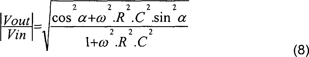
Bei
der Grenzfrequenz ωc
der Schaltung hat man folgendes Verhältnis:
Die Schaltung ist derart angeordnet, dass die Grenzfrequenz ωc in Bezug auf den im Rahmen der Anwendung gewünschten Frequenzbereich merklich mittig eingestellt ist.The Circuit is arranged such that the cutoff frequency ωc with respect noticeably on the frequency range desired in the application is set in the middle.
Um die Grenzfrequenz ist der Modul der Schaltung somit durch die folgende Formel gegeben:Around the cutoff frequency is the modulus of the circuit thus by the following Formula given:
![]()
![]()
Die Amplitude des Ausgangssignals ist somit unabhängig vom Winkel "α" zwischen dem empfangenen äusseren Signal Vin und den Empfangsachsen der Antennen, was auch dem gewünschten Ziel entspricht.The Amplitude of the output signal is thus independent of the angle "α" between the received external Signal Vin and the receive axes of the antennas, which is also the desired Target corresponds.
Jede
der beiden Antennen
Die
Empfangseinheit
Wie
auf
Die
beiden Spannungsquellen E1 und E2 liefern die folgenden entsprechenden
Spannungen:
Es ist wichtig festzuhalten, dass die Lösungen des Standes der Technik nämlich nicht die Situation vorsehen, wo die Antennen des Empfängers unterschiedlich sind, wohingegen diese Situation in der Lösung gemäss der Erfindung einbezogen ist.It It is important to note that the solutions of the prior art namely Do not provide the situation where the antennas of the receiver are different whereas this situation is included in the solution according to the invention is.
In
gleicher Weise, wie im Fall der Schaltung der
Zuerst
wird die Übertragungsfunktion
berechnet, wenn die Spannungsquelle E1 aktiviert ist und die Spannungsquelle
E2 kurzgeschlossen ist. Diese erste Übertragungsfunktion ermöglicht,
den Beitrag der ersten Antenne

Dann
wird die Übertragungsfunktion
berechnet, wenn die Spannungsquelle 
Die gesamte Übertragungsfunktion der Schaltung ist durch die Summe der beiden Funktionen, die weiter oben gemäss dem Überlagerungstheorem berechnet worden sind, gegeben:The entire transfer function The circuit is characterized by the sum of the two functions that continue above according to the overlay theorem have been calculated given:
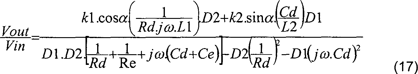
Da man weiss, dass der Modul dieser Übertragungsfunktion unabhängig vom Winkel "α" sein muss, impliziert dies, dass der Zähler der vorhergehenden Formel unabhängig von "α" ist, und man erhält also die folgende Formel, indem man D1 und D2 entwickelt:There it is known that the modulus of this transfer function is independent of Angle "α" must be implied this, that the counter independent of the preceding formula of "α" is, and you get so the following formula, by developing D1 and D2:
![]()
![]()
Diese Gleichung bietet viele Freiheitsgrade, was die Bestimmung der Werte der verschiedenen Elemente relativ komplex macht. Im Rahmen der Erfindung ist jedoch gezeigt worden, dass es möglich ist, das Mass der Freiheitsgrade zu beschränken, indem gewisse vorteilhaft definierte Beschränkungen vorgeschrieben werden.These Equation offers many degrees of freedom, what the determination of the values makes the various elements relatively complex. As part of the However, it has been shown that it is possible to measure the degree of degrees of freedom restrict, by prescribing certain advantageous defined restrictions.
Deshalb betrifft ein weiterer Gegenstand der Erfindung ebenfalls die Methode für die Bestimmung der Werte der Komponenten, die für diesen tragbaren Empfänger verwendet werden können.Therefore another aspect of the invention also relates to the method for the Determining the values of the components used for this portable receiver can be.
Eine erste interessannte Bedingung ist, eine Beschränkung in Abhängigkeit vom gewünschten Durchlassbereich im gegebenen Frequenzbereich des Senders und des Empfängers vorzuschreiben. Die Werte der Induktivitäten L1 und L2 der Spulen werden ebenfalls vorgeschrieben, wie auch die positiven Empfindlichkeitskoeffizienten k1 und k2 der Antennen. Ferner ist die Abstimmfrequenz ω0, die auch Arbeitsfrequenz genannt wird, bekannt, wie auch die Merkmale am Eingang der Empfangseinheit.A first condition is a constraint dependent of the desired Passband in the given frequency range of the transmitter and the receiver prescribe. The values of the inductances L1 and L2 of the coils become also prescribed, as well as the positive sensitivity coefficients k1 and k2 of the antennas. Furthermore, the tuning frequency is ω0, too Working frequency is known, as well as the features on Input of the receiving unit.
Um die Werte der verwendeten Komponenten zu bestimmen, geht man anhand der vorhergehenden Gleichung von der Unabhängigkeit des Signals Vout in Bezug auf den Winkel "α" aus, und man nimmt ebenfalls an, dass der gewünschte Durchlassbereich dieser Behauptung nicht entgegenwirkt.Around To determine the values of the components used, it is based on the previous equation of the independence of the signal Vout in Reference to the angle "α" off, and you take also indicate that the desired Passage of this claim does not counteract.
Ausgehend von diesen vorläufigen Hypothesen kann man zwei "α"-Werte wählen, um die Bedingungen zu bestimmen, welche durch eine Durchlassbereich- und/oder Verstärkungsbeschränkung impliziert werden. Man wählt zum Beispiel die Werte 0 und π/2, was die folgenden Wertepaare liefert: (cosα = 1; sinα = 0) bzw. (cosα = 0; sinα = 1).outgoing from these preliminary ones Hypotheses you can choose two "α" values to to determine the conditions implied by a passband and / or gain constraint become. You choose for example the values 0 and π / 2, which yields the following value pairs: (cosα = 1, sinα = 0) or (cosα = 0; sinα = 1).
Ausgehend von den zuvor berechneten allgemeinen Gleichungen sucht man die für die Elemente D1 und D2 möglichen Ausdrücke. Es ist festzuhalten, dass das System unter der Bedingung, dass die ω2-Ausdrücke von komplexen ω-Ausdrücken und nicht von reellen ω-Ausdrücken herrühren, durchführbar ist.Starting from the previously calculated general equations one looks for the expressions possible for the elements D1 and D2. Note that the system is feasible under the condition that the ω 2 terms originate from complex ω expressions rather than from real ω expressions.
Man
stellt also folgende Formeln auf:
Um "α" auszuschalten wählt man vorzugsweise die beiden
folgenden Bedingungen:
Im Rahmen der Erfindung ist gezeigt worden, dass die Wahl dieser beiden Bedingungen drei vorteilhafte Auswirkungen mit sich bringt.in the The invention has shown that the choice of these two Conditions have three beneficial effects.
Erstens
weisen die durch die Antennen gebildeten Schwingkreise eine gleiche
Resonanzfrequenz auf, die auf die Annullierung der Orthogonalitätsbedingung
zurückzuführen ist:
Zweitens weisen die beiden Schwingkreise eine gleiche entsprechende Ladung auf, d.h. eine gleiche Abstimmfrequenz und eine Aufrechterhaltung der Orthogonalität, wobei die Bedingungen im Durchlassbereich um die Abstimmfrequenz ω0 berücksichtigt werden müssen:Secondly the two oscillating circuits have the same corresponding charge on, i. a same tuning frequency and a maintenance the orthogonality, the conditions in the passband around the tuning frequency ω0 taken into account Need to become:
![]()
![]()
Dieser Ausdruck ermöglicht ebenfalls, die Güte des Empfängers einzustellen.This Expression allows also, the goodness Recipient adjust.
Drittens
erhält
man ausgehend von der Gleichheit der Module bei der Abstimmfrequenz ω0 und bei Annullierung
der Resonanzausdrücke
die folgende Gleichung für
die Verstärkung:
Diese drei Auswirkungen ermöglichen vorteilhaft, Bedingungen für die Frequenz aufgrund von der ersten, für die Ladung aufgrund von der zweiten bzw. für die Verstärkung aufgrund von der dritten zu erhalten.These enable three effects favorable conditions for the frequency due to the first, for the charge due to the second or for the reinforcement due to receive from the third.
Um die Werte der Komponenten dieser Schaltung einfach zu berechnen, hat man vorteilhaft bemerkt, dass die Ausgangsspannung Vout in zeitlich verschobener Weise bis auf einen Verstärkungskoeffizienten der Spannung des empfangenen äusseren Signals Vin entspricht. Es ist festzuhalten, dass dieser Koeffizient in einem begrenzten Frequenzbereich wenig variiert. Es ist ebenfalls festzuhalten, dass die Werte der Komponenten modifiziert werden können, um die eventuellen Streuelemente zu bilden.Around simply calculate the values of the components of this circuit, It has advantageously been noted that the output voltage Vout in time shifted way except for a gain coefficient of the voltage of the received external Signal Vin corresponds. It should be noted that this coefficient varies little in a limited frequency range. It is too note that the values of the components are modified can, to form the possible scattering elements.
Es ist noch zu bemerken, dass die zwei durch die beiden Antennen definierten Eingänge zwei entsprechenden Parallelschwingkreisen gleichgestellt werden können. Einer umfasst zum Beispiel die Komponenten L1, C1 und R1, die mit Rd parallelgeschaltet sind, und der andere umfasst L2, R2 und C2, die mit Cd parallelgeschaltet sind.It It should be noted that the two are defined by the two antennas inputs two corresponding parallel resonant circuits are equalized can. One includes, for example, the components L1, C1 and R1, which with Rd are connected in parallel, and the other comprises L2, R2 and C2, which are connected in parallel with Cd.
Diese beiden Bemerkungen zeigen, dass es genügt, den Verlauf der Erregung im Bereich eines der Eingangsschwingkreise zu untersuchen, anstatt den Durchlassbereich im Bereich des Ausgangs untersuchen zu müssen. Man untersucht zum Beispiel den zweiten Schwingkreis, der L2, R2 und C2, die mit Cd parallelgeschaltet sind, umfasst.These Both remarks show that it is sufficient, the course of the excitement in the area of one of the input resonant circuits, instead of to examine the passband at the output. you examines, for example, the second resonant circuit, the L2, R2 and C2, which are connected in parallel with Cd includes.
Man hat den durch die Wahl der Abstimmfrequenz ω0 festgelegten Wert ω0·L2, was ermöglicht, die Komponente C2, die mit Cd parallelgeschaltet ist, herzuleiten. Ebenso hat man die durch die nötige Empfindlichkeit festgelegte Güte, was ermöglicht, R2 herzuleiten.you has the value determined by the choice of the tuning frequency ω0 ω0 · L2, which allows derive the component C2, which is connected in parallel with Cd. Likewise, one has the necessary Sensitivity specified quality, what makes possible Derive R2.
Man kann vorteilhaft auf die Verteilung zwischen der Kapazität der beiden Kondensatoren C2 und Cd einwirken, um die Verstärkung am Ausgang zu optimieren. Es ist festzuhalten, dass ein Verstärker (nicht dargestellt) beispielsweise am Eingang der Empfangseinheit vorgesehen sein kann.you can be beneficial to the distribution between the capacity of the two Capacitors C2 and Cd act to optimize the gain at the output. It should be noted that an amplifier (not shown), for example may be provided at the entrance of the receiving unit.
Die Bestimmung dieser Komponenten ermöglicht, unter Anwendung der anderen obenbeschriebenen Gleichungen die Komponenten des anderen Schwingkreises zu bestimmen, insbesondere indem man sich auf die Resonanzfrequenz einstellt.The Determination of these components allows, using the other equations described above, the components of the other To determine the resonant circuit, in particular by looking at the Resonance frequency sets.
Wie dies klar ersichtlich ist, liegt die Amplitude des Ausgangssignals Vout, welches auch immer der Winkel zwischen dem durch die Identifikationseinheit ausgesendeten Signal und den Antennen des Identifizierers ist, in der Umhüllenden E und ist also merklich konstant, insbesondere um die Abstimmfrequenz, die zum Beispiel auf 125 KHz festgelegt wird, wobei der Frequenzbereich die Frequenzen von 120 bis 130 KHz deckt. Es ist festzuhalten, dass es sehr gut möglich ist, eine Abstimmfrequenz in irgendeiner Grössenordnung, und insbesondere in der Grössenordnung von dem MHz und dem GHz, zu wählen.As this is clearly apparent, lies the amplitude of the output signal Vout, whatever the angle between the through the identification unit emitted signal and the antennas of the identifier, in the envelope E and is thus noticeably constant, in particular around the tuning frequency, which is set to, for example, 125 KHz, with the frequency range covers the frequencies from 120 to 130 KHz. It should be noted that it is very possible is a tuning frequency of any order, and in particular in the order of magnitude from the MHz and the GHz.
Es ist festzuhalten, dass das resistive Element sowie das kapazitive Element insbesondere geeignet angeschlossene Transistoren sein können.It It should be noted that the resistive element as well as the capacitive Element may be particularly suitably connected transistors.
Es ist selbstverständlich, dass die Beschreibung nur als Beispiel gegeben ist, und dass andere Ausführungsformen, insbesondere Durchführungsarten der Methode für die Bestimmung der Komponenten, Gegenstand der vorliegenden Erfindung sein können.It is self-evident, that the description is given by way of example only and that others Embodiments, especially types of implementation the method for the determination of the components, object of the present invention could be.
Claims (6)
Applications Claiming Priority (1)
| Application Number | Priority Date | Filing Date | Title |
|---|---|---|---|
| EP01205244A EP1324506B1 (en) | 2001-12-28 | 2001-12-28 | Portable receiver with two antennas |
Publications (2)
| Publication Number | Publication Date |
|---|---|
| DE60123091D1 DE60123091D1 (en) | 2006-10-26 |
| DE60123091T2 true DE60123091T2 (en) | 2007-04-05 |
Family
ID=8181561
Family Applications (1)
| Application Number | Title | Priority Date | Filing Date |
|---|---|---|---|
| DE60123091T Expired - Lifetime DE60123091T2 (en) | 2001-12-28 | 2001-12-28 | Portable receiver with two antennas |
Country Status (2)
| Country | Link |
|---|---|
| EP (1) | EP1324506B1 (en) |
| DE (1) | DE60123091T2 (en) |
Cited By (1)
| Publication number | Priority date | Publication date | Assignee | Title |
|---|---|---|---|---|
| DE102011012230A1 (en) * | 2011-02-24 | 2012-08-30 | Giesecke & Devrient Gmbh | Method for operating a data carrier and data carrier with an antenna structure |
Families Citing this family (2)
| Publication number | Priority date | Publication date | Assignee | Title |
|---|---|---|---|---|
| FR3028074B1 (en) * | 2014-11-04 | 2016-11-11 | Smart Packaging Solutions | IMPROVED ANTENNA FOR CONTACTLESS CHIP CARD |
| PL3452957T3 (en) * | 2016-05-01 | 2021-12-13 | Smart Packaging Solutions (Sps) | Improved antenna for contactless chip card |
Family Cites Families (4)
| Publication number | Priority date | Publication date | Assignee | Title |
|---|---|---|---|---|
| US5912925A (en) * | 1995-05-18 | 1999-06-15 | Aura Communications, Inc. | Diversity circuit for magnetic communication system |
| DE19718423A1 (en) * | 1997-04-30 | 1998-11-05 | Siemens Ag | Portable signal receiver |
| FR2784524B1 (en) * | 1998-10-12 | 2006-07-07 | Dassault Electronique | IMPROVED ANTENNA, IN PARTICULAR FOR A NON-CONTACT BADGE READER |
| FR2792129B1 (en) * | 1999-04-07 | 2006-07-28 | Valeo Securite Habitacle | PORTABLE SIGNAL RECEIVER WITH MULTIPLE ANTENNAS |
-
2001
- 2001-12-28 DE DE60123091T patent/DE60123091T2/en not_active Expired - Lifetime
- 2001-12-28 EP EP01205244A patent/EP1324506B1/en not_active Expired - Lifetime
Cited By (1)
| Publication number | Priority date | Publication date | Assignee | Title |
|---|---|---|---|---|
| DE102011012230A1 (en) * | 2011-02-24 | 2012-08-30 | Giesecke & Devrient Gmbh | Method for operating a data carrier and data carrier with an antenna structure |
Also Published As
| Publication number | Publication date |
|---|---|
| DE60123091D1 (en) | 2006-10-26 |
| EP1324506B1 (en) | 2006-09-13 |
| EP1324506A1 (en) | 2003-07-02 |
Similar Documents
| Publication | Publication Date | Title |
|---|---|---|
| DE102006055752B4 (en) | Super-regenerative receiver | |
| DE102006020422B4 (en) | Passive Entry and / or Passive Go system and associated operating procedures | |
| DE102020116007A1 (en) | ON-CHIP HARMONIC FILTERING FOR HIGH FREQUENCY (RF) COMMUNICATIONS | |
| DE10005558A1 (en) | Vehicle data communications device uses dual channel communications microwave frequencies for intermediate frequency processing by conventional parts | |
| DE3883404T2 (en) | Ferrite-free, non-reciprocal phase shifter and circulator. | |
| DE10244173B4 (en) | Antenna arrangement for a magnetic resonance apparatus, magnetic resonance antenna system, magnetic resonance apparatus and method for coupling two antenna groups | |
| DE102015226150B4 (en) | Radio device for a vehicle locking system and method for calibrating such a radio device | |
| DE10325396A1 (en) | Circuit arrangement for phase modulation for backscatter-based transponder has control unit that can selectively connect voltage sources to varactor connection(s) depending on desired phase angle | |
| DE69312133T2 (en) | Tunable high-frequency filter | |
| EP2003659A1 (en) | Monolithically integrated inductivity | |
| DE60123091T2 (en) | Portable receiver with two antennas | |
| DE60129068T2 (en) | Control circuit for magnetic field transmission antenna with RLC circuit | |
| DE69728599T2 (en) | Multiband radio | |
| EP1257051B1 (en) | FM Demodulator using adjacent canal suppression | |
| DE1673244B2 (en) | SPECTROMETER FOR MAGNETIC NUCLEAR RESONANCE | |
| DE102014113910A1 (en) | Antenna circuit for near-field antennas | |
| DE1919625A1 (en) | Receiver input circuit, especially for medium wave | |
| DE102009019724A1 (en) | Transponder e.g. active transponder, for use in reader of radio frequency identification-system, has two antennae designed as coils that are connected in parallel or in series at antenna unit connected to input of electronic circuit | |
| DE60207547T2 (en) | Portable receiver with reduced dispersion | |
| DE60123087T2 (en) | Portable receiver with low dispersion | |
| WO2010000690A1 (en) | Receiver arrangement, particularly for use in motor vehicles | |
| EP2192009B1 (en) | Identifier for an electronic access system and electronic immobiliser | |
| DE102004038837B4 (en) | Electronic anti-theft system with correlated transmit / receive antennas | |
| DE102007041512B4 (en) | Safety and locking device in motor vehicles with a combined indoor and outdoor antenna | |
| DE102004036837B4 (en) | Self-cleaning exhaust air chamber and cleaning system for an exhaust air chamber |
Legal Events
| Date | Code | Title | Description |
|---|---|---|---|
| 8364 | No opposition during term of opposition |