DE60019992T2 - Arrangement and method for cellular communication by satellite with control of the beam diagram of the antennas - Google Patents

Arrangement and method for cellular communication by satellite with control of the beam diagram of the antennas Download PDF

Info

Publication number
DE60019992T2
DE60019992T2 DE60019992T DE60019992T DE60019992T2 DE 60019992 T2 DE60019992 T2 DE 60019992T2 DE 60019992 T DE60019992 T DE 60019992T DE 60019992 T DE60019992 T DE 60019992T DE 60019992 T2 DE60019992 T2 DE 60019992T2
Authority
DE
Germany
Prior art keywords
pattern
antenna
communication
antenna gain
cell
Prior art date
Legal status (The legal status is an assumption and is not a legal conclusion. Google has not performed a legal analysis and makes no representation as to the accuracy of the status listed.)
Expired - Lifetime
Application number
DE60019992T
Other languages
German (de)
Other versions
DE60019992D1 (en
Inventor
Eldad Perahia
Donald C. Wilcoxson
Current Assignee (The listed assignees may be inaccurate. Google has not performed a legal analysis and makes no representation or warranty as to the accuracy of the list.)
Northrop Grumman Systems Corp
Original Assignee
Northrop Grumman Corp
Priority date (The priority date is an assumption and is not a legal conclusion. Google has not performed a legal analysis and makes no representation as to the accuracy of the date listed.)
Filing date
Publication date
Application filed by Northrop Grumman Corp filed Critical Northrop Grumman Corp
Application granted granted Critical
Publication of DE60019992D1 publication Critical patent/DE60019992D1/en
Publication of DE60019992T2 publication Critical patent/DE60019992T2/en
Anticipated expiration legal-status Critical
Expired - Lifetime legal-status Critical Current

Links

Classifications

    • HELECTRICITY
    • H04ELECTRIC COMMUNICATION TECHNIQUE
    • H04BTRANSMISSION
    • H04B7/00Radio transmission systems, i.e. using radiation field
    • H04B7/14Relay systems
    • H04B7/15Active relay systems
    • H04B7/185Space-based or airborne stations; Stations for satellite systems
    • H04B7/1851Systems using a satellite or space-based relay
    • H04B7/18515Transmission equipment in satellites or space-based relays

Description

HINTERGRUND DER ERFINDUNGBACKGROUND THE INVENTION

In den letzten paar Jahren hat die Zahl kommerzieller zellularer Kommunikationssysteme (von denen die zellulare bzw. Mobiltelephonie nur ein Beispiel ist) dramatisch zugenommen. Erhöhte Nutzung zellularer Systeme unter Verbrauchern hat ein Verlangen nach Systemen mit höherer Kapazität zur Folge. In dem zunehmend konkurrenzbetonten Unternehmensumfeld, das die Mobiltelephonie geworden ist, bedingen Systeme mit höherer Kapazität effektivere und kostengünstigere Systeme. Einer der übergeordneten Begrenzungsfaktoren bei der Implementierung eines zellularen Systems ist die dem System zugewiesene Bandbreite bzw./-weite. Im allgemeinen erlaubt es eine Erhöhung der verfügbaren oder nutzbaren Bandbreite einem System, eine größere Zahl von Nutzern zu bedienen oder diesen Nutzern einen Service mit höherer Qualität bereitzustellen. In den letzten paar Jahren ist die tatsächliche der Mobiltelephonie zugewiesene Bandbreite fast konstant geblieben. Folgerichtig sind die Kosten, Bandbreite zu erlangen, dramatisch angestiegen. Daher sind effiziente Methoden zur Nutzung der existierenden Bandbreite notwendig, um die Kapazität zellularer Systeme zu erhöhen und dadurch eine kommerzielle Brauchbarkeit aufrechtzuerhalten.In The last few years have seen the number of commercial cellular communication systems (of which cellular or mobile is just one example) dramatically increased. Increased Use of cellular systems among consumers has a craving for systems with higher capacity result. In the increasingly competitive business environment, As a result of mobile telephony, higher capacity systems are more effective and cheaper Systems. One of the parent Limiting factors in the implementation of a cellular system is the bandwidth assigned to the system. In general it allows an increase the available or usable bandwidth of a system to serve a larger number of users or provide these users with higher quality service. In the last few years, the actual is the mobile phone allocated bandwidth remained almost constant. Are consistent the cost of gaining bandwidth has increased dramatically. Therefore are efficient methods for using the existing bandwidth necessary to the capacity increase cellular systems and thereby maintain commercial usability.

In zellularen Kommunikationssystemen ist die geographische Einsatz- bzw. Servicefläche des Systems auf der Erdoberfläche im allgemeinen in ein ineinander greifendes hexagonales Gitter unterteilt. Jedes hexagonale Gitterelement wird als Zelle bezeichnet. Zellen können geographisch fest sein, oder sie können durch Strahlpunkte von einem Satelliten definiert werden. Kommunikationssignale können innerhalb jeder Zelle durch Nutzung umlaufender Satelliten zum Verbraucher übertragen und von diesem empfangen werden.In cellular communication systems is the geographical deployment or service area of the system on the earth's surface generally divided into an interlocking hexagonal grid. Each hexagonal grid element is called a cell. cell can be geographically fixed, or they can be beamed by a satellite. Communication signals can be within each cell transmitted by using orbiting satellites to the consumer and be received by this.

Bei einem satellitengestützten zellularen System ist das allgemeine HF-Frequenz-Betriebsband in eine Zahl eindeutiger, nicht überlappender HF-Unterbänder bzw. -Subbänder unterteilt. Mehrere Zellen können das gleiche Frequenz-Subband verwenden. Wenn ein einzelnes Subband durch Zellen verwendet wird, die nahe beieinander liegen, kann das System gegenseitige Interferenz zwischen den Zellen erfahren. Gegenseitige Interferenz zwischen Zellen, die das gleiche Frequenz-Subband verwenden, ist als Co-Frequenzstörung bekannt. Um die Co-Frequenzstörung zu verringern, werden die Subbänder in einem Frequenzmuster so angeordnet, dass Zellen mit einem gemeinsamen Frequenz-Subband sich geographisch in einem vorbestimmten Mindestabstand von einander befinden. Das Frequenzmuster, durch welches die geographischen Zellen zugeordnet werden, kann als das Frequenz-Wiederverwendungsmuster bezeichnet werden. Die Zahl der Subbänder in dem Gesamtsystem und das zugehörige Frequenz-Wiederverwendungsmuster kann als das Frequenz-Wiederverwendungsschema bezeichnet werden. Beispielsweise kann das Frequenz-Wiederverwendungsschema die gesamte Systembandbreite in sieben Subbänder in einem 7-zu-1-Frequenz-Wiederverwendungsschema unterteilen.at a satellite-based cellular system is the general RF frequency band operating in a number more distinct, not overlapping RF sub-bands or subbands divided. Several cells can do that use the same frequency subband. When a single subband goes through Cells that are close to each other can be used by the system experience mutual interference between the cells. mutual Interference between cells using the same frequency subband is known as co-frequency interference. To the co-frequency noise to reduce the subbands in a frequency pattern arranged so that cells with a common Frequency subband is geographically at a predetermined minimum distance from each other. The frequency pattern through which the geographical Cells can be referred to as the frequency reuse pattern. The number of subbands in the overall system and the associated frequency reuse pattern may be referred to as the frequency reuse scheme. For example, the frequency reuse scheme may cover the entire System bandwidth in seven subbands in a 7-to-1 frequency reuse scheme.

Satellitengestützte zellulare Systeme können die Co-Frequenzstörung verringern, indem die Zahl der Subbänder auf Kosten einer Reduzierung der Gesamtkapazität des Systems erhöht wird. Es ist jedoch in vielen Fällen nicht machbar, die Zahl der Subbänder zu erhöhen, weil die gesamte Bandbreite beschränkt ist und jedes Subband eine vorbestimmte minimale Bandbreite zum Aufrechterhalten einer Kommunikation aufweisen muss (zusätzlich zur verringerten Kapazität des Systems, d. h., mit einer festen Zahl von Zellen, wird diese Frequenz um so weniger durch das ganze System hindurch wiederverwendet, je mehr Subbänder vorhanden sind). Daher beschränkt die Randbedingung, dass jedes Subband eine minimale vordefinierte Bandbreite aufweisen muss, die Zahl der Subbänder, in welche die gesamte Systembandbreite unterteilt werden kann. Die Beschränkung der Zahl der Subbänder beschränkt gleichzeitig sowohl die verfügbaren Frequenz-Wiederverwendungsmuster als auch den Abstand zwischen Zellen, die das gleiche Frequenz-Subband nutzen.Satellite-based cellular Systems can the co-frequency interference decrease by reducing the number of subbands at the expense of a reduction the total capacity of the system increases becomes. However, it is in many cases not feasible, the number of subbands to increase, because the entire bandwidth is limited and each subband one predetermined minimum bandwidth for maintaining communication must have (in addition to reduced capacity of the system, d. h., with a fixed number of cells, this frequency becomes the less reused throughout the system, ever more subbands available). Therefore limited the constraint that each subband has a minimum predefined Must have bandwidth, the number of subbands, in which the entire System bandwidth can be divided. The limitation of Number of subbands limited at the same time both the available Frequency reuse patterns as well as the distance between cells, that use the same frequency subband.

Alternativ kann das System um einen festgelegten Interferenzpegel zwischen Zellen herum aufgebaut sein, die in dem gleichen Frequenzband betrieben werden. Der Pegel der Co-Frequenzstörung ist allgemein proportional zum Abstand zwischen Zellen, die ein gemeinsames Subband nutzen. Wenn daher das System die maximale Co-Frequenzstörung festsetzt, muss das System gleichzeitig eine minimale Trennung zwischen Zellen, die in dem gleichen Frequenzbereich arbeiten, festlegen. Festlegen der minimalen Trennung zwischen Zellen, die in dem gleichen Frequenz-Subband arbeiten, schreibt das Frequenz-Wiederverwendungsschema und die Gesamtrahl von Subbändern vor, die notwendig sind, um das Frequenz-Wiederverwendungsschema zu implementieren, weil die Größe der hexagonalen Zellen des zellularen Systems konstant ist. Bestimmen der Gesamtzahl der Subbänder setzt auch die Bandbreite fest, die jedem Subband zugeordnet ist, weil die Gesamtbandbreite des Systems beschränkt ist.alternative The system can set a fixed interference level between Cells built around, which operated in the same frequency band become. The level of the co-frequency noise is generally proportional to the distance between cells using a common subband. Therefore, if the system sets the maximum co-frequency interference, the system must at the same time a minimal separation between cells that are in the same frequency range work, set. Set the minimum Separation between cells that work in the same frequency subband writes the frequency reuse scheme and total beam of subbands necessary to adopt the frequency reuse scheme implement because the size of the hexagonal Cells of the cellular system is constant. Determine the total number the subbands also sets the bandwidth associated with each subband because the overall bandwidth of the system is limited.

Die steigende kommerzielle Ausnutzung zellularer Kommunikationssystems verlangt, dass jeder Zelle eine zunehmende Bandbreite zugeordnet wird, um einen erhöhten Nutzerbedarf zu stützen, weil die jeder Zelle zugeordnete Bandbreite proportional zur Zahl der Sprach- oder Datennutzer ist, die gleichzeitig in jeder Zelle bedient werden können. Allgemein erhöht ein Erhöhen der Bandbreite pro Zelle die Zahl der Kunden, die das System in der Zelle zu jeder Zeit bedienen kann, wodurch die gesamte Profitabilität gesteigert wird. Weil jedoch die gesamte Bandbreite des zellularen Systems beschränkt ist, reduziert ein Erhöhen der jedem Subband zugeordneten Bandbreite notwendigerweise die Zahl der Subbänder, in die das System unterteilt werden kann. Eine Verringerung der Zahl der Subbänder dient dazu, das Frequenz-Wiederverwendungsmuster zu ändern, um zu bewirken, dass der Abstand zwischen Zellen, die das gleiche Frequenz-Subband verwenden, reduziert wird, was wiederum die Co-Frequenzstörung zwischen diesen Zellen erhöht. Um ein zellulares System mit einem höheren Volumen zu implementieren, muss jeder Zelle mehr Bandbreite zugewiesen werden. Dies bedeutet weniger Subbänder und daraus folgend eine größere Co-Frequenzstörung von Zellen, die das gleiche Frequenz-Subband verwenden, weil die Zellen enger zusammenstehen müssen.The increasing commercial exploitation of cellular communication systems requires every cell an increasing bandwidth is allocated to support increased user demand because the bandwidth associated with each cell is proportional to the number of voice or data users that can be serviced simultaneously in each cell. Generally, increasing the bandwidth per cell increases the number of customers that the system in the cell can serve at any one time, thereby increasing overall profitability. However, because the entire bandwidth of the cellular system is limited, increasing the bandwidth allocated to each subband necessarily reduces the number of subbands into which the system can be subdivided. A reduction in the number of subbands serves to change the frequency reuse pattern to cause the distance between cells using the same frequency subband to be reduced, which in turn increases the co-frequency interference between these cells. To implement a cellular system with a higher volume, more bandwidth must be allocated to each cell. This means fewer subbands and, consequently, a greater co-frequency interference of cells using the same frequency subband because the cells must be closer together.

Ein Verfahren zum Verringern der Co-Frequenzstörung kann es dem System erlauben, Zellen bei einem geringeren Abstand zueinander dem gleichen Subband zuzuweisen. Herabsetzen des Abstandes zwischen Zellen kann es wiederum dem System erlauben, mit weniger Subbändern bei einer entsprechend größeren Bandbreite pro Subband zu arbeiten. Eine größere Bandbreite pro Subband wiederum erlaubt mehr gleichzeitige Nutzer, was wiederum die Profitabilität des Serviceproviders bzw. Dienstleistungsanbieters erhöht.One Method for reducing co-frequency interference may allow the system Cells at a smaller distance from each other to the same subband assign. Reducing the distance between cells can turn it down allow the system with fewer subbands at one greater bandwidth to work per subband. A larger bandwidth per subband in turn allows more concurrent users, which in turn the profitability of the service provider or service provider.

Hinzu kommt, dass eine der hauptsächlichen Design- bzw. Entwurfseinschränkungen beim Auslegen eines digitalen zellularen Kommunikationssystems die Bitfehlerrate (BER) ist. Die BER bezeichnet allgemein die Rate, bei der Fehler in einem digitalen Datenstrom zwischen einem Sender bzw. Übertrager und einem Empfänger auftreten. In digitalen Datenströmen tritt ein Bitfehler auf, wenn der Sender einen digitalen Wert überträgt, aber der Empfänger einen unterschiedlichen digitalen Wert an den Nutzer ausgibt. Die Bitfehlerrate ist abhängig von der Verbindungsqualität zwischen Sender und Empfänger. Die Qualität der Verbindung zwischen Sender und Empfänger wird durch die Menge an Rauschen oder Interferenz in dem Umfeld beeinflusst, durch welchen der digitale Datenstrom hindurchgeht.in addition that comes one of the main ones Design or design restrictions when designing a digital cellular communication system the Bit error rate (BER) is. The BER generally refers to the rate at the error in a digital data stream between a transmitter or transformer and a receiver occur. In digital data streams However, if the transmitter transmits a digital value, a bit error occurs the recipient outputs a different digital value to the user. The Bit error rate is dependent from the connection quality between transmitter and receiver. The quality The connection between sender and receiver is determined by the amount Noise or interference in the environment influenced by which the digital data stream goes through.

Satellitengestützte zellulare Systeme können Rauschen oder Interferenz durch Modifizieren des Verstärkungsmusters einer Antenne des Satelliten kompensieren, welche den digitalen Datenstrom überträgt bzw. aussendet oder empfängt. Auf der Empfängerseite stellt die Antennenverstärkung die Empfindlichkeit der Antenne gegenüber dem eingehenden Signal dar. Auf der Senderseite ist die Antennenverstärkung proportional zu dem Leistungspegel, auf dem aussendete Signale während einer Übertragung ausgesendet werden. Zellulare Systeme sind allgemein so aufgebaut, dass sie Servicenutzer überall in einer gegebenen Zelle bedienen, und dabei eine vorgegebene maximale BER (benötigte Design-BER genannt) bereitstellen. Falls an irgendeinem Punkt in der Zelle auf der Oberfläche das System nicht in der Lage ist, die vorbestimmte maximale BER aufrecht zu erhalten, werden an diesem Punkt Kommunikationen bzw. Datenübertragungen mit dem Nutzer spürbar beeinträchtigt. Daher muss die Antennenverstärkung (und das Verstärkungsmuster) für eine gesamte Zelle ausreichend sein, um einen minimalen Signalpegel aufrecht zu erhalten, und zwar unabhängig von Rauschen oder Interferenz, die von dem Nutzer in der Zelle erfahren wird.Satellite-based cellular Systems can Noise or interference by modifying the gain pattern compensate an antenna of the satellite, which the digital Data stream transmits or sends out or receives. On the receiver side represents the antenna gain the sensitivity of the antenna to the incoming signal At the transmitter side, the antenna gain is proportional to the power level, on the emitted signals during a transmission to be sent out. Cellular systems are generally structured that they service users everywhere operate in a given cell, with a given maximum BER (needed Called design BER). If at any point in the cell on the surface the system is unable to maintain the predetermined maximum BER At this point, communications or data transmissions are received noticeable with the user impaired. Therefore, the antenna gain (and the reinforcement pattern) for one entire cell be sufficient to maintain a minimum signal level to receive, independently noise or interference experienced by the user in the cell becomes.

Bei satellitengestützten zellularen Systemen kann die Qualität der Verbindung zwischen Sender und Empfänger als Verhältnis zwischen dem gewünschten Signal- oder Trägerpegel und dem Pegel aus Rauschen plus Interferenz ausgedrückt werden. Das Verhältnis zwischen Trägerstärke und Pegel von Rauschen plus Interferenz kann beschrieben werden als C/(N+I). In vielen Fällen kann die Co-Frequenzstörung den Rauschen-plus-Interferenz-Term dominieren, was es erlaubt, den oben genannten Ausdruck als C/I anzunähern. Jedoch ist in vielen Systemen das Hintergrundrauschen ein signifikanter Faktor, und daher ist das Verhältnis C/(N+I) allgemein von Interesse. Das Verhältnis C/(N+I) ist wichtig beim Design eines zellularen Systems, weil es ein Maß für die Systemleistung ist. Ein hohes C/(N+I)-Verhältnis bewirkt eine verbesserte BER, da die Bitfehlerrate (BER) durch das Verhältnis von Träger zu Rauschen-plus-Interferenz C/(N+I) bestimmt. Folglich wird ein zellulares System mit einem hohen C/(N+I)-Verhältnis eine niedrige BER aufweisen und umgekehrt.at satellite-based cellular systems can improve the quality of the connection between transmitters and receiver as a ratio between the desired Signal or carrier level and the level of noise plus interference. The relationship between vehicle strength and Level of noise plus interference can be described as C / (N + I). In many cases can the co-frequency interference dominate the noise plus interference term, which allows the to approximate the above expression as C / I. However, in many Background noise is a significant factor, and therefore is the ratio C / (N + I) generally of interest. The ratio C / (N + I) is important in Designing a cellular system because it is a measure of system performance. One high C / (N + I) ratio causes an improved BER, since the bit error rate (BER) is determined by the relationship from carrier to noise-plus interference C / (N + I) determined. Consequently, a cellular system with a high C / (N + I) ratio have a low BER and vice versa.

In der Vergangenheit sind zellulare Systeme vorgeschlagen worden, welche einen Leistungspegel durch Wahl einer maximalen BER für Nutzer im Gesamtsystem auswählen. Dadurch legen herkömmliche Systeme einen einheitlichen Leistungspegel über die gesamte geographische Zelle. In herkömmlichen satellitengestützten Kommunikationssystemen beruht die kleinste Systemleistung (und dadurch die größte akzeptable BER) auf der Lage in der Zelle mit dem niedrigsten C/(N+I)-Verhältnis.In In the past, cellular systems have been proposed which a power level by choosing a maximum BER for users in the overall system. Thereby lay traditional Systems have a uniform power level across the whole geographical area Cell. In conventional satellite-based Communication systems based the smallest system performance (and thereby the largest acceptable BER) on the location in the cell with the lowest C / (N + I) ratio.

Mit anderen Worten stellen herkömmliche satellitengestützte zellulare Systeme eine minimale Antennenverstärkung an dem Punkt in einer Zelle mit dem niedrigsten C/(N+I)-Verhältnis bereit, welche ausreicht, um ein BER sicherzustellen, das kleiner ist als die maximale vorbestimmte BER. In aus der Vergangenheit bekannten Antennenentwürfen, repräsentiert die minimale Antennenverstärkung am Zellenpunkt des niedrigsten C/(N+I)-Verhältnisses einen Antennenverstärkungspegel, der weit unterhalb der maximalen Antennenverstärkung für die Antenne liegt. Im allgemeinen stellen herkömmliche Antennen ein Antennenverstärkungsmuster über die Zelle bereit, wobei das Muster einen Spitzen-Verstärkungspegel im Zentrum der Zelle und minimale Verstärkungspegel an den Rändern bzw. Grenzen der Zelle aufweist. Der minimale Signal- (oder Träger)-Pegel am Zellenrand muss den Rauschen-plus-Interferenz-Pegel um einen gewünschten Betrag überschreiten, um eine vorbestimmte BER zu erreichen. Wenn daher bei aus der Vergangenheit bekannten Antennen der Trägerpegel am Zellenrand so erhöht wird, dass er gerade den Rauschen-plus-Interferenz-Pegel überschreitet, überschreitet der Trägerpegel im Zentrum der Zelle den Rauschen-plus-Interferenz-Pegel bedeutend. Folglich wird eine große Menge an Leistung dabei verschwendet, Nutzer im Zentrum der Zelle zu bedienen.In other words, conventional satellite-based cellular systems provide a minimal antenna Nine gain at the point in a cell with the lowest C / (N + I) ratio sufficient to ensure a BER that is less than the maximum predetermined BER. In antenna designs known from the past, the minimum antenna gain at the cell point of the lowest C / (N + I) ratio represents an antenna gain level that is well below the maximum antenna gain for the antenna. In general, conventional antennas provide an antenna gain pattern across the cell, the pattern having a peak gain level in the center of the cell and minimum gain levels at the edges of the cell. The minimum signal (or carrier) level at the cell edge must exceed the noise plus interference level by a desired amount to achieve a predetermined BER. Therefore, in prior art antennas, if the carrier level at the cell edge is increased to just exceed the noise plus interference level, then the carrier level in the center of the cell significantly exceeds the noise plus interference level. As a result, a large amount of power is wasted serving users in the center of the cell.

In der Vergangenheit sind Antennen für zellulare Satellitensysteme entworfen worden, um eine minimale Verstärkung am Rand einer geographischen Zelle zu bekommen, um einen ausreichenden Signalpegel sicherzustellen. Frühere Antennen sind auch entworfen worden, um Nebenstrahlungskeulen auf einen gewünschten Pegel zu verringern, um die Interferenz zu verringern.In the past are antennas for cellular satellite systems designed to provide minimal reinforcement on the edge of a geographical Cell to ensure a sufficient signal level. earlier Antennas have also been designed to spot collision lobes a desired one Reduce levels to reduce interference.

In einem verwandten Ansatz, stellt EP-A-0 549 220 (Motorola) ein Zellenmanagement-Verfahren und eine Vorrichtung bereit, welche Antennenabdeckungsmuster (d. h., den geographischen "Fußabdruck") als Funktion der Zeit und/oder Position in der Umlaufbahn modifizieren, und zwar durch Ändern der Zahl oder Größe oder Lage oder Aktivität individueller Zellen dadurch, dass diese im Fall von "Lücken" eingeschaltet werden, oder ausgeschaltet werden, wenn der Antennenfußabdruck von einem Satelliten den Antennenfußabdruck von einem anderen Satelliten überdeckt und sich eine Redundanz der Abdeckung und eine mögliche Kommunikationsinterferenz ergibt.In In a related approach, EP-A-0 549 220 (Motorola) provides a cell management method and method Device ready which antenna cover pattern (i.e., the geographical "footprint") as a function of Modify time and / or position in orbit by changing the number or size or Location or activity individual cells by turning them on in the case of "gaps" or off be when the antenna footprint from one satellite the antenna footprint from another Satellites covered and get a redundancy of coverage and possible communication interference results.

In einem herkömmlichen zellularen Satellitensystem ist das Antennenverstärkungsmuster für einen gesamten Punktstrahl bekannt, welcher dadurch C/(N+I) an jeder Stelle über das System herüber bestimmt. Bei herkömmlichen Antennen kann sich jedoch das Antennenverstärkungsmuster kein konstantes C/(N+I) über die Zelle leisten. Stattdessen ist das Verhältnis von Träger zu Rauschen-plus-Interferenz C/(N+I) im Zentrum der Zelle viel größer als an den Rändern der Zelle. Wenn die Antenne ein C/(N+I)-Verhältnis bereitstellt, das nicht über die gesamte Zelle konstant ist, werden Ressourcen wie beispielsweise Leistung verschwendet, weil das Erreichen eines höheren C/(N+I)-Verhältnisses als dem minimal verlangten Verhältnis typischerweise dem System keinen zusätzlichen Wert verleiht.In a conventional one cellular satellite system is the antenna gain pattern for a whole Point beam known, which thereby C / (N + I) at any point on the System across certainly. In conventional Antennas, however, the antenna gain pattern can not be a constant C / (N + I) via to perform the cell. Instead, the ratio of carrier to noise-plus interference C / (N + I) in the center of the cell much larger than at the edges of the cell Cell. If the antenna provides a C / (N + I) ratio that does not exceed the Whole cell is constant, resources such as Power wasted because achieving a higher C / (N + I) ratio as the minimum required ratio typically does not add value to the system.

Herkömmliche Antennen können phasengesteuerte Anordnungen bzw. Antennengruppen ("phased arrays"), Reflektor-gestützte Antennen und dergleichen umfassen. Ein Antennenverstärkungsmuster wird durch Steuern der Phase und Amplitude von Signalen bestimmt, die von einer phasengesteuerten Antennengruppe bzw. Anordnung ausgesandt und von dieser empfangen werden. Bei Antennen, die mit Reflektoren ausgerüstet sind, wird das Antennenverstärkungsmuster durch die Größe und Kontur des Reflektors und das Antenneneinspeisungs-Design bestimmt.conventional Antennas can phased arrays, reflector-based antennas and the like. An antenna gain pattern is controlled by the phase and amplitude of signals determined by a phased array Antenna group or arrangement sent and received by this become. For antennas equipped with reflectors, the antenna gain pattern becomes by the size and contour of the reflector and the antenna feed design.

Ein Beispiel einer Reflektor-gestützten Antenne ist in US 5 134 423 , erteilt an Haupt ("Low Sidelobe Resistive Reflector Antenna"), offenbart. Das Haupt-Patent offenbart eine Antenne mit einem geformten Reflektor, der eine parabolische Antennenschüssel aufweist, die ein Isoliermaterial auf der Oberfläche eines geformten Reflektors enthält. Eine metallische Beschichtung ist auf der Oberfläche des geformten Reflektors abgeschieden worden. Die Dicke der konischen Metallbeschichtung auf der Oberfläche der Schüssel wird gemäß dem Radius der Schüssel variiert, um eine elektromagnetische Konizität bzw. Verjüngung zu erreichen. Wenn die konische Metallbeschichtung aufgebracht wird, wird ein geringer Widerstand bei größerer Dicke bereitgestellt, und ein fortschreitend höherer Widerstand, wenn weniger Metall abgeschieden wird. Die metallische Oberfläche kann beispielsweise aus Leitern wie beispielsweise Aluminium, Kupfer, Stahl, Eisen, Gold und Silber bestehen und kann auf die Oberfläche der Schüssel durch Abscheidungstechniken wie beispielsweise Sputtern, Aufdampfen, elektrolytische Abscheidung und Sprühbemalung bzw. Sprühbeschichtung aufgebracht werden.An example of a reflector-based antenna is shown in FIG US 5,134,423 , granted to Haupt ("Low Sidelobe Resistive Reflector Antenna"). The main patent discloses an antenna with a shaped reflector having a parabolic antenna dish containing an insulating material on the surface of a shaped reflector. A metallic coating has been deposited on the surface of the shaped reflector. The thickness of the conical metal coating on the surface of the bowl is varied according to the radius of the bowl to achieve electromagnetic tapering. When the conical metal coating is applied, a lower resistance is provided at a greater thickness, and a progressively higher resistance when less metal is deposited. For example, the metallic surface may be made of conductors such as aluminum, copper, steel, iron, gold, and silver and may be applied to the surface of the bowl by deposition techniques such as sputtering, vapor deposition, electrodeposition, and spray painting.

Es verbleibt ein Bedarf für ein Verfahren und eine Vorrichtung zur verbesserten Steuerung der Antennenverstärkung. Es ist eine Aufgabe der Erfindung, diesen Bedarf zu befriedigen.It there remains a need for a method and an apparatus for improved control of the Antenna gain. It is an object of the invention to meet this need.

ZUSAMMENFASSUNG DER ERFINDUNGSUMMARY THE INVENTION

Es ist eine Aufgabe der vorliegenden Erfindung, ein Antennenverstärkungsmuster bereitzustellen, das so geformt ist, dass es einem Interferenzmuster und Rauschen innerhalb einer Zelle eines satellitengestützten Telekommunikationssystems entspricht.It It is an object of the present invention to provide an antenna gain pattern which is shaped to give an interference pattern and noise within a cell of a satellite telecommunication system equivalent.

Es ist eine weitere Aufgabe der vorliegenden Erfindung, ein Antennenverstärkungsmuster bereitzustellen, bei dem eine Hauptstrahlungskeule so geformt ist, dass ein minimales Verhältnis von Träger zu Rauschen-plus-Interferenz innerhalb jeder Zelle eines satellitengestützten Telekommunikationssystems an Zellgrenzen (im Vergleich zu herkömmlichen Antennen) erhöht wird.It Another object of the present invention is an antenna gain pattern in which a main lobe is shaped that a minimal relationship from carrier to noise-plus interference within each cell of a satellite based telecommunications system at cell boundaries (compared to conventional antennas) is increased.

Es ist eine weitere Aufgabe der vorliegenden Erfindung ein Antennenverstärkungsmuster für ein satellitengestütztes Telekommunikationssystem bereitzustellen, welches eine übergroße Trägersignalstärke im Zentrum von Zellen innerhalb des Systems vermeidet.It Another object of the present invention is an antenna gain pattern for a satellite-based Telecommunication system to provide an oversized carrier signal strength in the center of cells within the system.

Es ist eine weitere Aufgabe der vorliegenden Erfindung, ein Antennenverstärkungsmuster so zu steuern, dass der Frequenz-Wiederverwendungsabstand reduziert wird, der gebraucht wird, um Interferenzen zwischen Zellen, die ein gemeinsames Frequenz-Subband verwenden, zu verhindern.It Another object of the present invention is an antenna gain pattern so that the frequency reuse distance is reduced What is needed is interference between cells that a common frequency subband use, prevent.

Es ist eine weitere Aufgabe der vorliegenden Erfindung, ein Antennenverstärkungsmuster zu steuern, um Datenübertragungsraten zu erhöhen und einen Aufwand zur Kanalkodierung zu reduzieren.It Another object of the present invention is an antenna gain pattern to control data transfer rates to increase and to reduce an effort for channel coding.

Es ist eine weitere Aufgabe der vorliegenden Erfindung, ein Verfahren zum Steuern einer Antennenverstärkung bereitzustellen, welche die Kapazität und den Durchsatz der Telekommunikationssatelliten erhöht.It Another object of the present invention is a method for controlling an antenna gain provide the capacity and throughput of telecommunications satellites elevated.

Diese und andere Aufgaben werden gelöst mittels eines satellitengestützten Telekommunikationssystems, welches mit Nutzern kommuniziert, die innerhalb einer vorbestimmten Kommunikationsfläche lokalisiert sind, wie beispielsweise einer geographisch festen Zelle. Die Kommunikationsflächen haben ein zugeordnetes Interferenzmuster. Das Interferenzmuster korrespondiert mit der Größe der Interferenz, die jedem Punkt innerhalb der Kommunikationsfläche zugeordnet ist. Das satellitengestützte Kommunikationssystem umfasst einen Satelliten mit einer Antenne zum Empfangen und/oder Übermitteln bzw. Senden von Kommunikationssignalen zu und von dem erdgebundenen Nutzer. Die Antenne ist so aufgebaut oder wird so dynamisch gesteuert, dass ein vorbestimmtes Antennenverstärkungsmuster über die Kommunikationsfläche bereitgestellt wird. Das Antennenverstärkungsmuster bildet die Sende-/Empfangsverstärkung an jedem gegebenen Punkt innerhalb der Kommunikationsfläche ab.These and other tasks are solved by means of a satellite Telecommunication system that communicates with users who are located within a predetermined communication area, such as a geographically fixed cell. The communication surfaces have an associated interference pattern. The interference pattern corresponds with the size of the interference, which is assigned to every point within the communication area. The satellite-based communication system includes a satellite with an antenna for receiving and / or transmitting or transmitting communication signals to and from the terrestrial Users. The antenna is constructed or dynamically controlled a predetermined antenna gain pattern over the communication area provided. The antenna gain pattern forms the transmit / receive gain any given point within the communication area.

Gemäß einer bevorzugten Ausführungsform der vorliegenden Erfindung werden ein Verfahren und eine Vorrichtung bereitgestellt zum Steuern der durch einen Übertrager bzw. Sender und/oder Empfänger eines Satelliten innerhalb des satellitengestützten Telekommunikationssystems definierten Verstärkung. Der Sender/Empfänger erzeugt ein gewünschtes Antennenverstärkungsmuster, das mindestens einer Kommunikationsfläche zugeordnet ist, wie beispielsweise einer festen oder mobilen geographischen Zelle, die durch das satellitengestützte Telkommunikationssystem definiert wird. Die bevorzugte Ausführungsform umfasst das Bestimmen eines Interferenzmusters, das einer interessierenden Kommunikationsfläche zugeordnet ist. Sobald das Interferenzmuster identifiziert worden ist, wird dann ein gewünschtes Antennenverstärkungsmuster festgestellt. Es wird bevorzugt, wenn das Antennenverstärkungsmuster dem Interferenzmuster und Rauschen für die Kommunikationsfläche entspricht. Sobald ein Antennenverstärkungsmuster festgestellt worden ist, werden der Sender und/oder der Empfänger so gesteuert, dass das gewünschte Antennenverstärkungsmuster für die Kommunikationsfläche bereitgestellt wird. Die bevorzugte Ausführungsform der vorliegenden Erfindung kann mittels eines Prozessors in dem Satelliten ausgeführt werden oder mittels eines Prozessors in einer Erdstation, welche wiederum eine adaptive phasengesteuerte Anordnung steuert, die als Sender und/oder Empfänger des Satelliten funktioniert. Alternativ kann ein gewünschtes Antennenverstärkungsmuster bereitgestellt werden, indem ein Reflektor in einer Antenne so aufgebaut wird, dass er eine gewünschte Oberflächenkontur aufweist, welche im Betrieb ein vorbestimmtes Verstärkungsmuster erzeugt.According to one preferred embodiment The present invention relates to a method and an apparatus provided for controlling by a transmitter and / or receiver a satellite within the satellite telecommunication system defined reinforcement. The transmitter / receiver creates a desired Antenna gain pattern, the at least one communication area is assigned, such as a fixed or mobile geographical cell created by the satellite-based telecommunication system is defined. The preferred embodiment includes determining an interference pattern associated with a communication area of interest is. Once the interference pattern has been identified, then a desired one Antenna gain pattern detected. It is preferable if the antenna gain pattern matches the interference pattern and noise for the communication area equivalent. Once an antenna gain pattern has been detected is, the transmitter and / or the receiver are controlled so that the desired Antenna gain pattern for the communication area provided. The preferred embodiment of the present invention Invention may be carried out by means of a processor in the satellite or by means of a processor in an earth station, which in turn controls an adaptive phased array, acting as a transmitter and / or recipient the satellite works. Alternatively, a desired Antenna gain pattern be provided by a reflector in an antenna so constructed that he will be a desired one Has surface contour, which generates a predetermined gain pattern during operation.

KURZE BESCHREIBUNG DER ZEICHNUNGENSHORT DESCRIPTION THE DRAWINGS

1 zeigt eine exemplarische konstante BER-Kurve für einen typischen Bereich von Antennenverstärkung und C/I (dem Verhältnis von Trägerpegel zu Interferenzpegel) gemäß einer bevorzugten Ausführungsform der vorliegenden Erfindung; 1 Figure 14 shows an exemplary constant BER curve for a typical range of antenna gain and C / I (the carrier level to interference level ratio) according to a preferred embodiment of the present invention;

2 zeigt das Hauptstrahlungskeulen-Muster für einen (Standard-) Normal-Reflektor, eine konstante BER in der Anwesenheit von Rauschen und Interferenz und eine konstante BER in einem Interferenz-dominierten System gemäß einer bevorzugten Ausführungsform der vorliegenden Erfindung; 2 Figure 12 shows the main lobe pattern for a (standard) normal reflector, a constant BER in the presence of noise and interference, and a constant BER in an interference dominated system according to a preferred embodiment of the present invention;

3 zeigt eine Antennenverstärkung gegen C/I-Leistung für einen (Standard-) Normal-Reflektor mit einer benötigten konstanten BER-Kurve, und zwar gezeigt gemäß einer bevorzugten Ausführungsform der vorliegenden Erfindung; 3 Figure 12 shows antenna gain versus C / I power for a (standard) normal reflector with a required constant BER curve, shown in accordance with a preferred embodiment of the present invention;

4 zeigt eine Antennenverstärkung gegen C/I-Leistung für ein konstantes C/I-Hauptstrahlungskeulen-Muster mit einer benötigen konstanten BER-Kurve, und zwar gezeigt gemäß einer bevorzugten Ausführungsform der vorliegenden Erfindung; 4 Figure 4 shows an antenna gain vs. C / I power for a constant C / I mainlobe pattern with a constant BER curve, shown in accordance with a preferred embodiment of the present invention;

5 zeigt eine Antennenverstärkung gegen C/I-Leistung für ein konstantes C/(N+I)-Hauptstrahlungskeulen-Muster (dem Verhältnis von Träger-Pegel to Rauschpegel-plus-Interferenzpegel) mit einer benötigen konstanten BER-Kurve, und zwar gezeigt gemäß einer bevorzugten Ausführungsform der vorliegenden Erfindung; 5 FIG. 12 shows an antenna gain vs. C / I power for a constant C / (N + I) main lobe pattern (carrier level to noise level plus interference level) with a constant BER curve, shown in FIG preferred embodiment of the present invention;

6 zeigt ein zellulares System mit einem Frequenz-Wiederverwendungsmuster von 4:1 gemäß einer bevorzugten Ausführungsform der vorliegenden Erfindung; 6 shows a cellular system with a frequency reuse pattern of 4: 1 according to a preferred embodiment of the present invention;

7a zeigt das C/I für ein 4:1-Frequenz-Wiederverwendungmuster von Zellen für einen herkömmlichen Normalreflektor, wie er auf eine hexagonale Grundzelle bzw. Bodenzelle abgebildet wird; 7a Figure 4 shows the C / I for a 4: 1 frequency reuse pattern of cells for a conventional standard reflector as mapped to a hexagonal ground cell;

7b zeigt die Antennenverstärkung für einen herkömmlichen Normalreflektor, wie er auf eine hexagonale Grundzelle ausgerichtet ist; 7b shows the antenna gain for a conventional normal reflector, as it is aligned on a hexagonal ground cell;

7c zeigt den Vergleich zwischen einer BER-Kurve, die für ein Design benötigt wird, und den Punkten in einer Grundzelle für einen Normalreflektor; 7c shows the comparison between a BER curve needed for a design and the points in a basic cell for a normal reflector;

8a zeigt das C/I für ein 4:1-Frequenz-Wiederverwendungsmuster von Zellen für einen geformten Reflektor, der ein wie in 2 gezeigtes Hauptstrahlungskeulen-Muster umsetzt, und zwar ausgerichtet auf eine Grundzelle gemäß einer bevorzugten Ausführungsform der vorliegenden Erfindung; 8a Figure 4 shows the C / I for a 4: 1 frequency reuse pattern of cells for a shaped reflector which incorporates a, as in 2 converted main radiation lobe pattern, aligned to a basic cell according to a preferred embodiment of the present invention;

8b zeigt die Antennenverstärkung für einen geformten Reflektor, der ein wie in 2 gezeigtes Hauptstrahlungskeulen-Muster umsetzt, und zwar ausgerichtet auf eine Grundzelle gemäß einer bevorzugten Ausführungsform der vorliegenden Erfindung; 8b shows the antenna gain for a shaped reflector, the one as in 2 converted main radiation lobe pattern, aligned to a basic cell according to a preferred embodiment of the present invention;

8c zeigt einen Vergleich zwischen einer BER-Kurve für eine Designvorgabe und den Punkten innerhalb einer Grundzelle für einen geformten Reflektor, der das wie in 2 gezeigte Hauptstrahlungskeulen-Muster umsetzt, und zwar gemäß einer bevorzugten Ausführungsform der vorliegenden Erfindung; 8c FIG. 4 shows a comparison between a BER curve for a design default and the points within a basic shaped reflector cell, which is the same as in FIG 2 converted main lobe pattern, according to a preferred embodiment of the present invention;

9 zeigt einen herkömmlichen Interferenzpegel für eine typische Grundzelle; 9 shows a conventional interference level for a typical ground cell;

10 zeigt einen herkömmlichen Interferenzpegel für eine spezialisierte Grundzelle; 10 shows a conventional interference level for a specialized ground cell;

11 zeigt ein Antennenverstärkungsmuster für einen geformten Reflektor im Vergleich zu einem Antennenverstärkungsmuster für einen Normalreflektor gemäß einer bevorzugten Ausführungsform der vorliegenden Erfindung, wobei der Interferenzpegel der gleiche wie in 10 ist; 11 shows an antenna gain pattern for a shaped reflector compared to an antenna gain pattern for a normal reflector according to a preferred embodiment of the present invention, wherein the interference level is the same as in FIG 10 is;

12 zeigt ein Antennenverstärkungsmuster für einen geformten Reflektor für die spezialisierte Grundzelle aus 10 gemäß einer bevorzugten Ausführungsform der vorliegenden Erfindung; und 12 FIG. 12 shows an antenna gain pattern for a shaped reflector for the specialized ground cell 10 in accordance with a preferred embodiment of the present invention; and

13 zeigt ein Flussdiagramm gemäß einer bevorzugten Ausführungsform der vorliegenden Erfindung zum Bestimmen eines gewünschten Antennenverstärkungsmusters. 13 shows a flowchart according to a preferred embodiment of the present invention for determining a desired antenna gain pattern.

BESCHREIBUNG DER BEVORZUGTEN AUSFÜHRUNGSFORMENDESCRIPTION THE PREFERRED EMBODIMENTS

In einem zellularen Kommunikationssystem ist ein hauptsächlicher Leistungsgradmesser des Systems C/(N+I), welches das Verhältnis zwischen dem gewünschten Signal- oder Trägerpegel und dem Pegel von Rauschen plus Interferenz ist. In Systemen mit einer eingeschränkten Interferenz wird C/I, das Verhältnis von Trägerpegel zu Interferenzpegel, eine gute Annäherung an dieses Verhältnis. In typischen Systemen, in denen ein Hintergrundrauschen signifikant ist (obwohl vielleicht nicht dominant) wird jedoch ein Antennendesign, welches ein konstantes C/I über die gesamte Zelle bereitstellt, nicht notwendigerweise die optimale Leistung in Bezug auf die Systemparameter von C/(N+I) bereitstellen.In a cellular communication system, a major power meter of the system is C / (N + I), which is the ratio between the desired signal or carrier level and the level of noise plus interference. In systems with limited interference, C / I, the ratio of Carrier level to interference level, a good approximation to this ratio. However, in typical systems where background noise is significant (although perhaps not dominant), an antenna design that provides a constant C / I over the entire cell does not necessarily provide optimal performance with respect to the system parameters of C / (N + I ) provide.

Eine interessierende Systemdesignanforderung an das System ist es, eine benötigte Bitfehlerrate (BER) allen Nutzern bereitzustellen. Die benötigte Design-BER ist die maximal erlaubbare BER, welche eine Kommunikation erlaubt. Nutzer müssen eine BER erreichen, welche kleiner oder gleich der benötigten Design-BER ist. Gestützt auf das ausgewählte Modulationsschema, Kanalcodierung und Bandbreite, lässt sich eine benötigte Design-BER in ein minimales bevorzugtes C/(N+I) übersetzen. Wie oben ausgeführt, ist wünschenswert, allen Nutzern in einer Zelle ein vorbestimmtes minimales C/(N+I) bereitzustellen, um die Systemleistung zu verbessern und eine effiziente Nutzung der Systemressourcen sicherzustellen, wie beispielsweise eine Übertragungsleistung.A The system design request to the system of interest is a needed Bit error rate (BER) to provide all users. The required design BER is the maximum allowable BER that allows communication. Users need reach a BER that is less than or equal to the required design BER is. supported on the selected one Modulation scheme, channel coding and bandwidth, can be one needed Translate design BER into a minimal preferred C / (N + I). As stated above desirable, all users in a cell have a predetermined minimum C / (N + I) to improve system performance and efficient Ensure use of system resources, such as transmission performance.

Das gewünschte Antennen-Hauptstrahlungskeulen-Muster, um ein konstantes C/(N+I) über die Zelle zu sichern, kann beginnend mit der standardmäßigen Abwärtsstrecken- bzw. Downlink-Gleichung abgeleitet werden:

Figure 00120001
wobei: GT die Satelliten-Sende-Antennenverstärkung, PT die Sendeleistung, LP Pfadverluste, (G/T)Terminal die Anschluss-Antennenverstärkung über die System-Rauschtemperatur an dem Anschluss (im Gegensatz zur Rauschtemperatur des gesamten Raumfahrzeugs) ist, k die Boltzmann-Konstante ist und BRF die äquivalente Rauschbandbreite des Signals ist.The desired antenna main lobe pattern to secure a constant C / (N + I) across the cell can be derived starting with the standard downlink equation:
Figure 00120001
where: G T is the satellite transmit antenna gain, P T is the transmit power, L P is path losses, (G / T) terminal is the port antenna gain above the system noise temperature at the port (as opposed to the noise temperature of the entire spacecraft), k is the Boltzmann constant and B RF is the equivalent noise bandwidth of the signal.

Die Standard-Abwärtsstrecken-Gleichung kann dann als Term der Verstärkung der Sendeantenne als Funktion von C/I umgeschrieben werden.The Standard downlink equation can then as a term of reinforcement the transmit antenna is rewritten as a function of C / I.
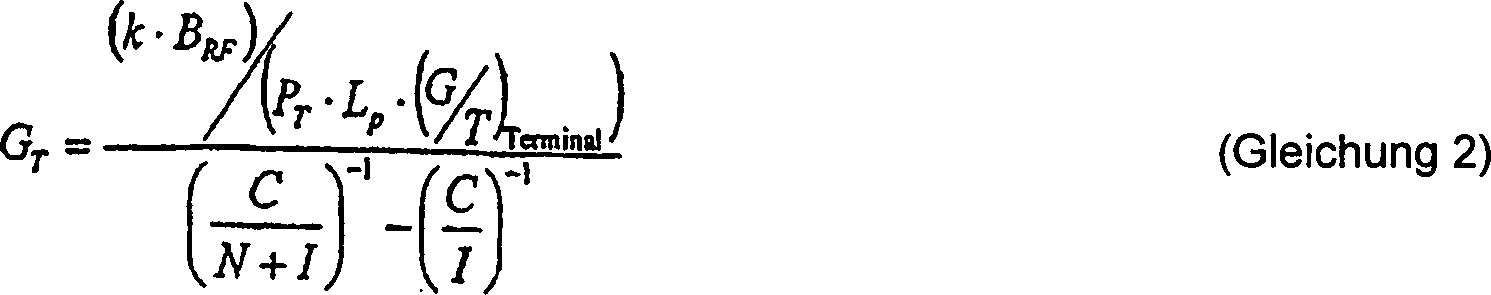
Figure 00120002
Figure 00120002

Aus Gleichung 2 kann eine konstante BER-Kurve, wie in 1 gezeigt, aufgefunden werden. 1 zeigt die Kurve 10 konstanter BER (konstante BER = konstante C/(N+I)-Kurve) über einen typischen Bereich von Antennenverstärkung und C/I-Betriebsbedingungen. 1 zeigt einen bevorzugtes Aufbau dahingehend, dass dann, falls an allen Stellen in der Grundzelle (C/I variiert von Stelle zu Stelle), die Nutzer an diesen Stellen (spezifische C/I-Werte) mit einer Antennenverstärkung auf der Konstant-BER-Kurve in 1 versorgt werden, alle Nutzer in der Zelle die gleiche benötigte Design-BER erreichen würden. In anderen Worten: Falls an allen Stellen in einer Grundzelle Nutzer mit einer (Antennenverstärkung und C/I)-Paar auf der Konstant-BER-Kurve 10 in 1 versorgt würden, würden alle Nutzer in der Zelle mit der gleichen benötigten Design-BER versorgt werden. Es wäre dann wünschenswert, dass sämtliche (Verstärkung und C/I)-Paare auf die Konstant-BER-Kurve 10 fallen, weil die (Verstärkung und C/I)-Paare, die darüber und zur rechten Seite der Konstant-BER-Kurve 10 liegen, die mindestens notwendige Systemverstärkung und C/I überschreiten, und daher verschwenderisch mit Systemressourcen umgehen, während (Verstärkung und C/I)-Paare, die nach unten und zur Linken der Konstant-BER-Kurve 10 fallen, nicht ausreichen, um das benötigte Design-BER-Systemdesign bereitzustellen.From Equation 2, a constant BER curve, as in FIG 1 shown to be found. 1 shows the curve 10 constant BER (constant BER = constant C / (N + I) curve) over a typical range of antenna gain and C / I operating conditions. 1 shows a preferred construction in that if, at all locations in the basic cell (C / I varies from location to location), the users at these locations (specific C / I values) with an antenna gain on the constant BER curve in 1 supplied, all users in the cell would reach the same required design BER. In other words, if at all points in a ground cell there are users with an (antenna gain and C / I) pair on the constant BER curve 10 in 1 would be supplied to all users in the cell with the same required design BER. It would then be desirable to have all (gain and C / I) pairs on the constant BER curve 10 fall because the (gain and C / I) pairs that go above and to the right of the constant BER curve 10 and thus excessively deal with system resources while (gain and C / I) pairs going down and to the left of the constant BER curve are at least necessary system gain and C / I 10 not enough to provide the required BER system design.

Weil der Interferenzpegel (I) in der Zelle bekannt ist, wird für alle Nutzer in der Zelle ein konstantes BER dann sichergestellt, falls das Hauptstrahlungskeulen-Antennenverstärkungsmuster so entwickelt wird, dass an jedem Punkt in der Zelle das (Antennenverstärkung und C/I)-Paar an diesem Punkt auf die Konstant-BER-Kurve 10 in 1 fällt. Zur Bestimmung des benötigten Antennenverstärkungsmusters (Hauptstrahlungskeulenmuster), wird Gleichung (2) umgeschrieben auf eine Antennenverstärkung als eine Funktion der Interferenz I. Auch wird hier C/(N+I) mit dem benötigten C/(N+I) ersetzt, welches die benötigte Design-BER repräsentiert. Es ist auch anzumerken, dass das C in dem C/I-Term umgeschrieben wird als (G/T)Terminal(LP)(PT)(T)(GT), wobei T die äquivalente Rauschtemperatur an dem Anschluss ist. Die Terme werden in der folgenden Form umgeändert: Because the interference level (I) in the cell is known, a constant BER is then ensured for all users in the cell if the main lobe antenna gain pattern is developed so that (antenna gain and C / I) at each point in the cell. Couple at this point on the constant BER curve 10 in 1 falls. To determine the required antenna gain pattern (main lobe pattern), equation (2) is rewritten to antenna gain as a function of interference I. Also, here C / (N + I) is replaced with the required C / (N + I) which needed Design BER represents. It should also be noted that the C in the C / I term is rewritten as the (G / T) terminal (L P ) (P T ) (T) (G T ), where T is the equivalent noise temperature at the port. The terms are in the changed the following form:

Figure 00130001
Figure 00130001

Gleichung 3 ergibt das gewünschte Hauptstrahlungskeulen-Muster, das eine konstante BER (C/(N+I)) über die gesamte Zelle bereitstellt. Zusätzlich ist in den Fällen, in denen das System bezüglich einer Interferenz begrenzt ist, der Effekt des Rauschterms klein, und die konstante BER kann durch ein konstantes C/I angenähert werden.equation 3 gives the desired Main lobe pattern, which has a constant BER (C / (N + I)) over the provides the entire cell. additionally is in the cases in which the system regarding interference is limited, the effect of the noise term is small, and the constant BER can be approximated by a constant C / I.

2 zeigt Beispiele von Hauptstrahlungskeulen-Mustern für ein Hauptstrahlungskeulen-Muster 20 für einen (Standard-)Normalreflektor, ein Hauptstrahlungskeulen-Muster 24 für eine konstante BER in Anwesenheit von Rauschen und Interferenz (C/N+I) und ein Hauptstrahlungskeulenmuster 22 für eine konstante BER in einem Interferenz-dominierten System (C/I). Die Strahlungskeulenmuster werden in Termen einer normalisierten Antennenverstärkung als eine Funktion der Gradabweichung von der Peilrichtung gezeigt (dies ist ein zweidimensionaler Schnitt aus einem dreidimensionalen Muster). Die Peilrichtung ist die genaue Mitte der Hauptstrahlungskeule, die auf dem Strahl ist, der von der Antenne nach unten auf die Mitte der Grundzelle gerichtet ist. Daher ist die Peilrichtung für jede auf eine Zelle gerichtete Hauptstrahlungskeule definiert und kann unterschiedlich von der geometrischen Peilrichtung des Reflektors sein. Die Peilrichtung ist auf die Mitte der Grundzelle gerichtet, und wegen des großen Abstandes von der erhöhten Position des Satelliten zur Grundzelle weichen die Kanten der Grundzelle nur einige Zehntel Grad von der Peilrichtung ab. 2 shows examples of main lobe patterns for a main lobe pattern 20 for a (standard) normal reflector, a main lobe pattern 24 for a constant BER in the presence of noise and interference (C / N + I) and a main radiation lobe pattern 22 for a constant BER in an interference dominated system (C / I). The radiation lobe patterns are shown in terms of a normalized antenna gain as a function of the degree deviation from the bearing direction (this is a two-dimensional intersection of a three-dimensional pattern). The bearing direction is the exact center of the main lobe, which is on the beam, which is directed from the antenna down to the center of the ground cell. Therefore, the direction of the bearing is defined for each main lobe directed to a cell and may be different from the geometric direction of the reflector. The bearing direction is directed towards the center of the ground cell, and because of the large distance from the elevated position of the satellite to the ground cell, the edges of the ground cell deviate only a few tenths of a degree from the bearing direction.

Das Keulenmuster 20 aus 2 für eine (Standard-) Normalreflektor-Antenne weist auf ein Strahlungsmuster einer Hauptstrahlungskeule einer typischen Satellitenantenne, wie sie heutzutage verwendet wird. Es ist zu beachten, dass das Hauptstrahlungskeulenmuster 20 der typischen Antenne in der Mitte der Grundzelle maximal ist, was als 0° von der Peilrichtung entlang der x-Achse von 2 angezeigt wird. Die Hauptstrahlungskeulenmuster für konstante BER in der Anwesenheit des Keulenmusters 24 für das Rauschen und die Interferenz (C/N+I) als auch das Keulenmuster 22 in Interferenz-dominierten Systemen (C/I) sind ebenfalls in 2 gezeigt. Es ist zu beachten, dass beide Muster eine reduzierte Verstärkung in Peilrichtung haben, welche ansteigt, wenn das Muster sich von der Peilrichtung weg bewegt, und die dann abfällt. Das C/(N+I)-Muster kann eine etwas höhere normalisierte Antennenverstärkung in Peilrichtung haben als das C/I-Muster, während das C/I-Muster eine etwas höhere normalisierte Antennenverstärkung an den "Buckeln" hat, welche auftreten, wenn das Verstärkungsmuster sich von der Peilrichtung entfernt.The club pattern 20 out 2 for a (standard) normal reflector antenna indicates a radiation pattern of a main lobe of a typical satellite antenna as used today. It should be noted that the main lobe pattern 20 the typical antenna in the center of the basic cell is maximum, which is 0 ° from the bearing direction along the x-axis of 2 is shown. The main radiation pattern for constant BER in the presence of the lobe pattern 24 for the noise and the interference (C / N + I) as well as the lobe pattern 22 in interference-dominated systems (C / I) are also in 2 shown. It should be noted that both patterns have a reduced gain in the direction of the bearing, which increases as the pattern moves away from the direction of the bearing and then drops. The C / (N + I) pattern may have a slightly higher normalized antenna gain in the bearing direction than the C / I pattern, while the C / I pattern has a slightly higher normalized antenna gain at the "humps" that occur when the gain pattern moves away from the direction of the bearing.

Die Hauptstrahlungskeulenmuster 22, 24 geformter Antennen können in einer Vielzahl von Arten umgesetzt werden, einschließlich der Verwendung geformter Reflektoren, adaptiver Antennenanordnungen, Strahlformern, geänderten oder mehrfachen Zuführungen an einem geformten oder ungeformten Reflektor und dergleichen. Zur Zeit ist eine kommerziell verwendbare Option die Verwendung eines Normalreflektors. Der Normalreflektor kann aus einer parabolischen Antennenschüssel bestehen, die ein Dielektrikum auf der Oberfläche aufweist, auf dem eine Metallschicht abgeschieden worden ist. Die Dicke der Metallschicht auf der Oberfläche der Schüssel wird gemäß dem Radius der Schüssel variiert, wodurch ein elektromagnetischer Konus erzeugt wird, um das gewünschte Hauptstrahlungskeulenmuster herzustellen. Die metallische Oberfläche kann beispielsweise aus Leitern wie Aluminium, Kupfer, Stahl, Eisen, Gold und Silber bestehen und kann auf der Oberfläche der Schüssel durch Abscheidetechniken wie beispielsweise Sputtern, Aufdampfen, elektrolytische Abscheidung und Sprühbeschichtung abgeschieden werden.The main radiation pattern 22 . 24 Shaped antennas can be implemented in a variety of ways, including the use of shaped reflectors, adaptive antenna arrays, beam shapers, modified or multiple feeds to a shaped or unshaped reflector, and the like. At present, a commercially viable option is the use of a standard reflector. The normal reflector may consist of a parabolic antenna dish having a dielectric on the surface on which a metal layer has been deposited. The thickness of the metal layer on the surface of the bowl is varied according to the radius of the bowl, thereby generating an electromagnetic cone to produce the desired main lobe pattern. For example, the metallic surface may be made of conductors such as aluminum, copper, steel, iron, gold, and silver and may be deposited on the surface of the bowl by deposition techniques such as sputtering, evaporation, electrodeposition, and spray coating.

3 zeigt die Leistungskurve 30 für die Antennenverstärkung, aufgetragen gegen C/I für einen typischen, heutzutage gebräuchlichen Reflektor im Vergleich zu den idealen Systemanforderungen der Kurve 32 für konstante BER. Die Normalreflektor-Kurve 30, die in 3 von links unten nach rechts oben läuft, repräsentiert das tatsächliche (Antennenverstärkung und C/I)-Paar für jeden Punkt in der hexagonalen Grundzelle. Jeder Punkt auf der Kurve 30 repräsentiert eine Lage in der Grundzelle. Ein Kurvensegment 35 bezeichnet den Bereich der Kurve 30, der unter und zur Linken des Schnittpunkts von Kurve 30 mit der Kurve 32 der benötigten Design-BER liegt. Kurvensegment 37 bezeichnet den Teil der Kurve 30, der überhalb und zur Rechten des Schnittpunkts von Kurve 30 mit Kurve 32 der benötigten Design-BER liegt. Punkte, die auf das Kurvensegment 35 unter und links von der Kurve 32 der benötigten Design-BER fallen, erfüllen nicht die Design-Anforderung und sind daher nicht geeignet, eine Kommunikation mit der benötigten Design-BER zu unterstützen. Punkte, die auf das Kurvensegment 37 oberhalb und zur Rechten der Kurve 32 der benötigten Design-BER fallen, übertreffen die Kurve 32 der benötigten Design-BER und erlauben daher eine Kommunikation, aber solche Lagen bzw. Orte sind nicht effizient in Bezug auf die Leistung; d. h., dass an solchen Orten der Trägerpegel viel höher als benötigt ist, um die benötigten Design-BER-Anforderungen zu erfüllen. 3 shows the power curve 30 for the antenna gain plotted against C / I for a typical reflector in use today compared to the ideal system requirements of the curve 32 for constant BER. The normal reflector curve 30 , in the 3 running from bottom left to top right, represents the actual (antenna gain and C / I) pair for each point in the hexagonal ground cell. Every point on the curve 30 represents a position in the basic cell. A curve segment 35 denotes the area of the curve 30 that is below and to the left of the intersection of curve 30 with the curve 32 the required design BER lies. curve segment 37 denotes the part of the curve 30 that is above and to the right of the intersection of curve 30 with curve 32 the required design BER lies. Points pointing to the curve segment 35 below and to the left of the curve 32 The required design BERs do not meet the design requirement and are therefore not suitable to support communication with the required design BER. Points pointing to the curve segment 37 above and to the right of the curve 32 fall short of the required design BER, outperform the curve 32 the required design BER and therefore allow communication, but sol locations are not efficient in terms of performance; that is, in such locations the carrier level is much higher than needed to meet the required design BER requirements.

Damit das in 3 gezeigte Normalreflektoren-System an allen Punkten innerhalb der hexagonalen Grundzelle arbeiten kann, müssen zusätzliche Schritte unternommen werden, um jeden Punkt 35 über die Kurve 32 der benötigten BER anzuheben. Die Leistungsanforderungen an das System können erfüllt werden durch konzeptionelles Bewegen der Kurve nach unten und zur Linken, so dass alle Punkte darüber und zur Rechten der Kurve liegen.So that in 3 As shown in Figure 1, normal reflectors can work at all points within the hexagonal ground cell, additional steps must be taken to each point 35 over the curve 32 raise the required BER. The performance demands on the system can be met by moving the curve down and to the left so that all points are above and to the right of the curve.

Einige der Elemente aus Gleichung 2 können modifiziert werden, um die Kurve konstanter BER zu verschieben. Beispielsweise verringert ein Reduzieren der Modulationsordnung das benötigte C/(N+I), was die Kurve nach unten und zur Linken verschiebt. Erhöhen der Menge der Kanalcodierung reduziert ebenfalls das benötigte C/(N+I); Erniedrigen der Signalrate reduziert BRF, was die Kurve nach unten verschiebt; Erhöhen von PT verschiebt die Kurve ebenfalls nach unten; und ein Erhöhen von (G/T)Terminal verschiebt die Kurve ebenfalls nach unten. Die bevorzugte Ausführungsform der vorliegenden Erfindung stellt eine effizientere Methode bereit, um die Systemanforderungen zu erfüllen, und zwar durch Bewegen der Punkte selbst, ohne die Systemressourcen zusätzlich zu belasten, welche benötigt werden, um die Kurve zu verschieben.Some of the elements in Equation 2 can be modified to shift the constant BER curve. For example, reducing the modulation order reduces the required C / (N + I), shifting the curve down and to the left. Increasing the amount of channel coding also reduces the required C / (N + I); Decreasing the signal rate reduces B RF , which shifts the curve down; Increasing P T also shifts the curve down; and increasing (G / T) terminal also shifts the curve down. The preferred embodiment of the present invention provides a more efficient method to meet the system requirements by moving the points themselves without adding to the system resources needed to move the curve.

4 zeigt die Antennenverstärkung-gegen-C/I-Leistung für das in 2 gezeigte Hauptstrahlungskeulenmuster mit konstantem C/I, wie es in einem zellularen System umgesetzt ist, das weder interferenzdominiert noch rauschdominiert ist. Jedes (Verstärkung und C/I)-Paar auf der Leistungskurve 40 entspricht einer Stelle in der Grundzelle. Die Kurve 42 mit konstanter BER schneidet die vertikale Kurve 40 konstanter C/I-Leistung. Ein Kurvensegment 45 bezeichnet den Bereich der Kurve 40, der unterhalb und zur Linken des Schnittpunkts von Kurve 40 mit Kurve 42 der benötigten Design-BER liegt. Ein Kurvensegment 47 bezeichnet den Bereich von Kurve 40, der oberhalb und zur Rechten des Schnittpunkts von Kurve 40 mit Kurve 42 der benötigten Design-BER liegt. Daher mag das in 2 gezeigte C/I-Hauptkeulenmuster für die gegebenen typischen Systemmerkmale (PT, LP, (G/T)Terminal, BRF und C/(N+I)Req), keine geeignete Systemantwort an allen Stellen auf dem Kurvensegment 45 in der Grundzelle bereitstellen. Jedoch wird das Hauptstrahlungskeulenmuster die Designanforderungen an anderen Stellen auf dem Kurvensegment 47 übertreffen, was bedeutet, dass das System nicht so effizient wie möglich ist, obwohl es Kommunikation mit der benötigten gewünschten BER (oder besser als dies) erlaubt. In anderen Worten: An einigen Stellen in der Grundzelle auf dem Kurvensegment 47 übertrifft das (Verstärkung-und-C/I)-Paar was benötigt wird, um die benötigte Design-BER zu erfüllen (Bereich der vertikalen Linie oberhalb der Kurve der benötigten Design-BER) und verschwendet daher Systemressourcen. An anderen Stellen in der Grundzelle auf Kurvensegment 45 verfehlt das (Verstärkungs- und C/I)-Paar die benötigte Design-BER (Bereich der vertikalen Linie unterhalb der Kurve für die benötigte Design-BER) und ist daher nicht ausreichend, um Kommunikationen innerhalb der System-Designparameter zu unterstützen. Daher müssen zusätzliche Schritte unternommen werden, damit diese Punkte die benötigte Design-BER für das System erfüllen. Dies könnte einbeziehen: Reduzieren der Modulationsordnung, Erhöhen der Kanalcodierung, Reduzierung der Signalrate, Erhöhen der Sendeleistung oder Erhöhen von (G/T)Terminal. Alle diese Optionen würden einen negativen Einfluss auf die Leistung des Gesamtsystems haben. 4 shows the antenna gain vs. C / I power for the in 2 shown main lobe patterns with constant C / I, as implemented in a cellular system that is neither interference dominated nor noise dominated. Each (gain and C / I) pair on the power curve 40 corresponds to a position in the basic cell. The curve 42 with constant BER intersects the vertical curve 40 constant C / I performance. A curve segment 45 denotes the area of the curve 40 that is below and to the left of the intersection of curve 40 with curve 42 the required design BER lies. A curve segment 47 indicates the range of curve 40 , which is above and to the right of the intersection of curve 40 with curve 42 the required design BER lies. Therefore, that likes in 2 shown C / I main lobe patterns for the given typical system features (P T , L P , (G / T) terminal , B RF and C / (N + I) Req ), no suitable system response at all locations on the curve segment 45 in the ground cell. However, the main lobe pattern becomes the design requirements elsewhere on the curve segment 47 which means that the system is not as efficient as possible, although it allows communication with the required BER (or better than this). In other words: in some places in the basic cell on the curve segment 47 exceeds the (gain-and-C / I) pair needed to satisfy the required design BER (range of vertical line above the curve of the required design BER) and therefore wasting system resources. Elsewhere in the basic cell, turn segment 45 If the (gain and C / I) pair misses the required design BER (area of the vertical line below the curve for the required design BER) and is therefore not sufficient to support communications within the system design parameters. Therefore, additional steps must be taken for these points to meet the required design BER for the system. This could include: reducing the modulation order, increasing the channel coding, reducing the signal rate, increasing the transmit power, or increasing the (G / T) terminal . All of these options would have a negative impact on overall system performance.

5 zeigt die Leistungskurve 50 von Antennenverstärkung gegen C/I das Konstant-BER- (d.h., das Konstant-(C/N+I)-) Hauptstrahlungskeulenmuster aus 2, das die gleichen Systemparameter (PT, LP), (G/T)Terminal, BRF und C/(N+I)Req) wie oben verwendet. Wie in den 3 und 4, korrespondiert jedes Paar von Verstärkung und C/I auf der Leistungskurve 50 in 5 mit einer Stelle in der Grundzelle. 5 zeigt, dass die Paare von Verstärkung und C/I auf der Leistungskurve 50 wie gewünscht entlang der Kurve 52 konstanter BER ausgerichtet sind. Daher stellt die Nutzung des in 5 shows the power curve 50 of antenna gain versus C / I, the constant BER (ie, the constant (C / N + I)) main radiation lobe pattern 2 using the same system parameters (P T , L P ), (G / T) terminal , B RF and C / (N + I) Req ) as above. As in the 3 and 4 , each pair corresponds to gain and C / I on the power curve 50 in 5 with a place in the basic cell. 5 shows that the pairs of gain and C / I on the power curve 50 as desired along the curve 52 are aligned constant BER. Therefore, the use of the in

2 gezeigten Hauptstrahlungskeulenmusters mit konstanter BER ein System mit konstanter, benötigter Design-BER bereit. Das konstante, benötigte Design-BER bedeutet, dass keine Systemressourcen verschwendet werden, noch zusätzliche Systemressourcen notwendig sind, um alle Grundpunkte in der Zelle bei mindestens der benötigten Design-BER zu betreiben. Daher ist die Lösung für konstantes, benötigtes Design-BER die effizienteste Lösung sowohl im Hinblick auf Systemgewicht, Größe, Leistung als auch Kapazität (wodurch Aufstellungskosten minimiert werden). 2 constant BER main beam pattern, a system with constant, required design BER ready. The constant, required design BER means that no system resources are wasted, nor additional system resources are needed to operate all the bases in the cell at least the required design BER. Therefore, the solution for constant, required design BER is the most efficient solution in terms of system weight, size, performance, and capacity (minimizing deployment costs).

Als ein Beispiel können diese Hauptstrahlungskeulenmuster wie in 6 gezeigt, in einem satellitengestützten zellularen Kommunikationssystem unter Verwendung einer 4-zu-1-Frequenz-Wiederverwendung umgesetzt werden. Der zellulare Kommunikationssatellit 60 kommuniziert in der Kommunikationsfläche, wie beispielsweise der Grundzelle 62, und nutzt dabei ein Gesamtfrequenzband, welches in vier Subbänder unterteilt worden sind, was ein 4-zu-1-Frequenz-Wiederverwendungsplan genannt wird. Der 4-zu-1-Frequenz-Wiederverwendungsplan bedeutet, dass die hervorgehobenen Zellen 64 alle durch das gleiche Frequenz-Subband bedient werden. Die anderen Zellen werden durch Frequenz-Subbänder bedient, welche von dem interessierenden Subband der Zelle in der Mitte unterschiedlich sind. Zwei Antennen-Hauptstrahlungskeulenmuster 66 sind auf Zellen unterschiedlicher Kofrequenz gerichtet. Das Hauptstrahlungskeulenmuster 66 erfüllt die konstante benötigte Design-BER, wie sie in 2 gezeigt ist.As an example, these main lobe patterns may be as in FIG 6 shown to be implemented in a satellite-based cellular communication system using 4-to-1 frequency reuse. The cellular communication satellite 60 communicates in the communication area, such as the basic cell 62 , and uses a total frequency band which has been divided into four subbands, which is called a 4-to-1 frequency reuse plan. The 4-to-1 frequency how The usage plan means that the highlighted cells 64 all served by the same frequency subband. The other cells are served by frequency subbands which are different from the sub-band of interest of the cell in the middle. Two antenna main radiation pattern 66 are directed to cells of different cortical frequency. The main radiation pattern 66 Meets the constant design BER needed, as in 2 is shown.

Die 7a und 7b zeigen das C/I und die Verstärkung für einen normalen, ungeformten Reflektor, welcher auf eine der hexagonalen Grundzellen 75 abgebildet wird. In 7a sind variierende Pegel von C/I in dB innerhalb der hexagonalen Grundzelle 75a als ein Konturdiagramm gezeigt. Der C/I-Pegel fällt von einem Maximum von ungefähr 16 dB an Punkt A 70 in der Mitte der Zelle 75a auf ein Minimum von ungefähr 10 dB an Punkt B 71 nahe des Randes bzw. der Kante von Zelle 75a ab. In 7b sind die variierenden Pegel der Antennenverstärkung in dB innerhalb der hexagonalen Grundzelle 75b als ein Konturdiagramm gezeigt. In 7b fällt die Verstärkung von einem Maximum bei ungefähr 46,5 dB bei Punkt A 72 in der Mitte der Zelle 75b auf ein Minimum von ungefähr 43,25 dB bei Punkt B 73 in der Nähe der Kante von Zelle 75b ab.The 7a and 7b show the C / I and gain for a normal, unshaped reflector pointing to one of the hexagonal base cells 75 is shown. In 7a are varying levels of C / I in dB within the hexagonal ground cell 75a shown as a contour plot. The C / I level drops from a maximum of about 16 dB at point A 70 in the middle of the cell 75a to a minimum of about 10 dB at point B 71 near the edge or edge of cell 75a from. In 7b are the varying levels of antenna gain in dB within the hexagonal ground cell 75b shown as a contour plot. In 7b the gain falls from a maximum at about 46.5 dB at point A. 72 in the middle of the cell 75b to a minimum of about 43.25 dB at point B 73 near the edge of cell 75b from.

7c zeigt einen Vergleich der Punkte A und B aus den 7a und 7b mit der benötigten Design-BER. Die benötigte Design-BER-Kurve 76 ist wie die Leistungskurve 77, die alle Punkte innerhalb der hexagonalen Grundzelle repräsentiert, gezeigt. Punkt A 78, der räumlich in der Mitte der Zelle liegt, befindet sich weit überhalb und rechts von der Kurve. Daher übertrifft Punkt A 78 die Kurve 76 der benötigten Design-BER erheblich und wird eine Kommunikation bei einer besseren als der benötigten Design-BER unterstützen, ist aber verschwenderisch in den Systemressourcen. Punkt B 79 fällt unter die Kurve 76 der benötigten Design-BER und zu ihrer Linken und ist daher nicht ausreichend, um eine Kommunikation mit der benötigten Design-BER zu unterstützen. Folglich werden, um das System in diesem Falle mit der benötigten Design-BER zu betreiben, zusätzliche Systemressourcen benötigt, um Punkt B auf einen Punkt oberhalb der Kurve 76 der benötigten Design-BER anzuheben. Diese Leistungsverbesserung wird auch dazu dienen, den Abstand zwischen Punkt A 78 und der Kurve der benötigten Design-BER weiter zu vergrößern und daher seine Ineffizienz zu erhöhen und möglicherweise eine co-frequente Interferenz hinzuzufügen. 7c shows a comparison of the points A and B from the 7a and 7b with the required design BER. The required design BER curve 76 is like the power curve 77 , which represents all points within the hexagonal ground cell. point a 78 , which is spatially in the middle of the cell, is located well above and to the right of the curve. Therefore, point A surpasses 78 the curve 76 The design BER required and will support communication at a better than the required design BER, but is wasteful in system resources. Point B 79 falls under the curve 76 the required design BER and to their left and is therefore not sufficient to support communication with the required design BER. Consequently, to operate the system in this case with the required design BER, additional system resources are needed to point B to a point above the curve 76 to raise the required design BER. This performance improvement will also serve to increase the distance between point A 78 and to further increase the curve of the required design BER and therefore increase its inefficiency and possibly add co-frequency interference.

Die 8a und 8b zeigen das C/I und die Verstärkung für ein Hauptstrahlungskeulenmuster mit konstantem C/(N+I), wie oben abgeleitet und in 2 gezeigt, und zwar abgebildet auf eine der hexagonalen Grundzellen 85, so wie es mit einem gerichteten Reflektor umgesetzt werden könnte. In 8a sind, wie in 7a, die unterschiedlichen Pegel von C/I in dB innerhalb der hexagonalen Grundzelle 85a als Konturdiagramm gezeigt. In 8a fällt der C/I-Pegel von einem Maximum von ungefähr 13,1 dB an Punkt A 80 in der Mitte der Zelle 85a auf ein Minimum von ungefähr 11,8 dB an Punkt B 81 nahe der Kante bzw. des Randes von Zelle 85a. In 8b sind, wie in 7b, verschiedene Pegel der Antennenverstärkung in dB innerhalb der hexagonalen Grundzelle 85b als Konturdiagramm gezeigt. In 8b kann man sehen, dass die Verstärkung von einem Minimum von ungefähr 43,9 dB an Punkt A 82 in der Mitte der Zelle 85b auf ein Maximum von ungefähr 45,1 dB an Punkt B 83 in der Nähe des Randes der Zelle 85b ansteigt.The 8a and 8b show the C / I and gain for a main beam pattern with constant C / (N + I) as derived above and in FIG 2 shown on one of the hexagonal basic cells 85 as it could be implemented with a directional reflector. In 8a are, as in 7a , the different levels of C / I in dB within the hexagonal ground cell 85a shown as a contour diagram. In 8a the C / I level drops from a maximum of about 13.1 dB at point A. 80 in the middle of the cell 85a to a minimum of about 11.8 dB at point B 81 near the edge of cell 85a , In 8b are, as in 7b , various levels of antenna gain in dB within the hexagonal ground cell 85b shown as a contour diagram. In 8b it can be seen that the gain of a minimum of about 43.9 dB at point A 82 in the middle of the cell 85b to a maximum of about 45.1 dB at point B 83 near the edge of the cell 85b increases.

Wie in 7c oben gezeigt, zeigt 8c einen Vergleich von Punkten A und B aus 8a und 8b zu den Design-BER-Anforderungen. Auch hier ist die Kurve 86 der benötigten Design-BER wie die Kurve 87, die alle Punkte innerhalb der hexagonalen Grundzelle 85 repräsentiert, gezeigt. Man kann erkennen, dass beide Punkte A 88 und B 89, und tatsächlich alle Punkte innerhalb der Grundzelle, auf die Design-BER-Kurve 86 fallen. Daher können Kommunikationen bzw. Datenübertragungen an beiden Punkten A 88 und B 89 mit der Design-BER unterstützt werden und es sind keine zusätzlichen Systemressourcen notwendig. Das Satellitensystem mit geformtem Reflektor kann mit kleineren und leichteren Komponenten und mit einer geringeren Sendeleistung umgesetzt werden, was alles erhebliche kommerzielle Vorteile bringt.As in 7c shown above shows 8c a comparison of points A and B from 8a and 8b to the design BER requirements. Again, the curve 86 the required design BER like the curve 87 containing all points within the hexagonal ground cell 85 represented, shown. It can be seen that both points A 88 and B 89 , and indeed all points within the ground cell, on the design BER curve 86 fall. Therefore, communications at both points A 88 and B 89 supported with the design BER and no additional system resources are required. The shaped reflector satellite system can be implemented with smaller and lighter components and with lower transmit power, all of which brings significant commercial benefits.

Zusätzlich zeigt ein Designen bzw. Auslegen eines Systems um die Kurve konstanter BER bemerkenswerte Vorteile in den Fällen, in dem das Interferenzmuster in der hexagonalen Grundzelle nicht um den Mittelpunkt der Zelle herum zentriert ist. Dies kann gezeigt werden durch Vergleich von 7b, dem Verstärkungsmuster eines normalen Reflektors, mit 9, dem typischen Interferenzmuster 90 in den meisten hexagonalen Grundzellen. Sowohl das Normalreflektor-Verstärkungsmuster als auch das Interferenzmuster zeigen ihren größten Wert am Mittelpunkt der Zelle und sinken zu den Rändern der Zelle hin ab. In Fällen wie diesem würden Systemressourcen gebunden, um die benötigte Design-BER zu erreichen. Obwohl solch ein System nicht optimal effizient wäre, würde es einen kommerziell nutzbaren heutigen Stand der Technik repräsentieren.In addition, designing a system around the constant BER curve has notable advantages in cases where the interference pattern in the hexagonal ground cell is not centered around the center of the cell. This can be shown by comparing 7b , the gain pattern of a normal reflector, with 9 , the typical interference pattern 90 in most hexagonal ground cells. Both the normal-reflector gain pattern and the interference pattern show their greatest value at the center of the cell and sink toward the edges of the cell. In cases like this, system resources would be bound to achieve the required design BER. Although such a system would not be optimally efficient, it would represent a commercially available state of the art.

Jedoch ist bei einer Zahl von Situationen das in einer hexagonalen Grundzelle angetroffene Interferenzmuster nicht um den Mittelpunkt der Zelle herum zentriert. 10 zeigt ein beispielhaftes Interferenzmuster für eine hexagonale Zelle 100 am Rand einer Servicefläche bzw. Nutzungsfläche oder in Anwesenheit weniger anderer hexagonaler Zellen oder einer Zelle mit einem großen Winkel relativ zur Peilrichtung der Satellitenantenne. 10 zeigt, dass das Interferenzmuster im vorliegenden Fall erheblich von dem in 9 gezeigten Interferenzmuster abweicht. Das an eine Zelle angelegte Verstärkungsmuster muss ausreichend Verstärkung bereitstellen, um eine Kommunikation bei einer benötigten Design-BER zu erlauben. Daher ist das Anlegen eines Antennenverstärkungsmusters einer Normalantenne auf eine solche Zelle eines satellitengestützten Kommunikationssystems ziemlich ineffzient. Dies deshalb, weil die Stelle in der Zelle, welche mit der höchsten Verstärkung versorgt werden muss, die in 10 gezeigte obere Kante der Zelle 102 sein muss, während im Vergleich das Normalreflektor-Verstärkungsmuster an der Kante seine niedrigste Verstärkung der Zelle zeigt. Daher würde die Gesamtsystemleistung im großen Maße verringert werden müssen, um die benötigte Design-BER über die Zelle aufrechtzuerhalten.However, in a number of situations, the interference pattern encountered in a hexagonal ground cell is not centered around the center of the cell. 10 shows an exemplary interference pattern for a hexagonal cell 100 on the edge of a service area or use area or in the presence of us niger other hexagonal cells or a cell with a large angle relative to the direction of the satellite antenna. 10 shows that the interference pattern in the present case is considerably different from the one in 9 deviates interference pattern shown. The gain pattern applied to a cell must provide sufficient gain to allow communication at a required design BER. Therefore, applying an antenna gain pattern of a normal antenna to such a cell of a satellite based communication system is rather inefficient. This is because the location in the cell that needs to be supplied with the highest gain is the one in 10 shown upper edge of the cell 102 whereas, in comparison, the normal reflector gain pattern at the edge shows its lowest gain of the cell. Therefore, the overall system performance would have to be greatly reduced to maintain the required design BER across the cell.

Jedoch erzeugt das Anwenden der vorliegenden Erfindung, um das Interferenzmuster der Zelle in 10 auf die Kurve konstanter benötigter Design-BER abzustimmen, das Antennenverstärkungsmuster für einen geformten Reflektor, wie er in 11 gezeigt ist (gezeigt ist ein Schnitt bei x=0 entlang der y-Achse aus 12). 11 zeigt die Antennenverstärkungsmuster für den Normalreflektor 112 im Vergleich zu dem neuen Antennenverstärkungsmuster 110, das mittels eines geformten bzw. gerichteten Reflektors implementiert bzw. umgesetzt wird. Es ist zu beachten, dass, obwohl in diesem Fall ein geformter Reflektor verwendet wird, um das gewünschte Antennenverstärkungsmuster umzusetzen, dass Antennenverstärkungsmuster selbstverständlich auch durch verschiedene andere Mittel neben einem geformten Reflektor umgesetzt werden können, wie beispielsweise durch eine adaptive Antennenanordnung oder einen Strahlformer.However, applying the present invention to the interference pattern of the cell in FIG 10 to match the curve of constant design BER required, the antenna gain pattern for a shaped reflector as shown in FIG 11 is shown (shown is a section at x = 0 along the y-axis 12 ). 11 shows the antenna gain patterns for the normal reflector 112 compared to the new antenna gain pattern 110 which is implemented by means of a shaped reflector. It should be noted that although in this case a shaped reflector is used to implement the desired antenna gain pattern, it will be understood that antenna gain patterns may be translated by various other means besides a shaped reflector, such as an adaptive antenna array or beamformer.

Die sich ergebende Antennenverstärkung (in drei Dimensionen) für den Fall des geformten Reflektors ist in 12 gezeigt. Bei Vergleich von 12 mit 10 wird deutlich, dass die Antennenverstärkung für den geformten Reflektor mit dem Interferenzmuster der hexagonalen Grundzelle 120, wie sie in 10 gezeigt ist, übereinstimmt. (Wie hierbei gebräuchlich, ist dann in Bezug darauf, dass das Antennenverstärkungsmuster mit dem Interferenzmuster übereinstimmt, gemeint, dass das Antennen-Design bzw. die Antennenauslegung einen Cluster von (Antennenverstärkung gegen C/I)-Punkten mit einer Kurvenlinienanpassung erzeugt, bei dem ein größerer Teil ihrer Steigung zwischen Null und minus Unendlich liegt). Daher kann die benötigte Design-BER mit effizientestem, und daher preisgünstigstem, Leistungsverbrauch, Größe und Gewicht erreicht werden, weil die Antennenverstärkung des geformten Reflektor mit dem Interferenzmuster der Grundzelle 120 übereinstimmt.The resulting antenna gain (in three dimensions) for the case of the shaped reflector is in FIG 12 shown. When comparing 12 With 10 it becomes clear that the antenna gain for the shaped reflector with the interference pattern of the hexagonal basic cell 120 as they are in 10 shown matches. (As used herein, in reference to the antenna gain pattern coinciding with the interference pattern, it is meant that the antenna design generates a cluster of (antenna gain versus C / I) points with a curved line fit greater part of its slope is between zero and minus infinity). Therefore, the required design BER can be achieved with most efficient, and therefore inexpensive, power consumption, size and weight because the antenna gain of the shaped reflector matches the interference pattern of the fundamental cell 120 matches.

13 ist ein Blockdiagramm, das eine bevorzugte Ausführungsform der vorliegenden Erfindung zeigt. Zuerst muss das Interferenzmuster in der interessierenden Zelle bei Schritt 130 bestimmt werden. Als Zweites muss ein Antennenverstärkungsmuster, das mit dem Interferenzmuster der interessierenden Zelle entspricht, bei Schritt 132 identifiziert werden. Als Letztes muss das identifizierte Antennenverstärkungsmuster durch den Satelliten bei Schritt 134 bereitgestellt werden. In einer Ausführungsform der vorliegenden Erfindung ist das Interferenzmuster für die interessierende Zelle vor dem Satellitenstart vorgegeben, und eine Antenne wird so aufgebaut, dass sie ein entsprechendes Antennenverstärkungsmuster liefert. Die Antenne kann einen geformten Reflektor, Strahlformer oder eine adaptive Anordnung umfassen. In einer anderen Ausführungsform werden eine adaptive Anordnung, ein Strahlformer oder dergleichen dynamisch am Satelliten gesteuert, um das Antennenverstärkungsmuster des Interferenzmusters der Grundzelle zu treffen. Die dynamische Steuerung wird in Echtzeit durchgeführt. Allgemein werden sowohl das Hauptstrahlungskeulen-Antennenverstärkungsmuster und die Interferenzmuster zusammen ausgelegt, möglicherweise durch einen iterativen Prozess, so dass die Hauptstrahlungskeulen-Antennenverstärkung mit dem Interferenzmuster in der interessierenden Zelle übereinstimmt. 13 Fig. 10 is a block diagram showing a preferred embodiment of the present invention. First, the interference pattern in the cell of interest must be at step 130 be determined. Second, an antenna gain pattern corresponding to the interference pattern of the cell of interest must be used in step 132 be identified. Lastly, the identified antenna gain pattern by the satellite must be at step 134 to be provided. In one embodiment of the present invention, the interference pattern for the cell of interest is predetermined prior to satellite launch, and an antenna is constructed to provide a corresponding antenna gain pattern. The antenna may comprise a shaped reflector, beamformer or adaptive array. In another embodiment, an adaptive array, beamformer or the like is dynamically controlled at the satellite to hit the antenna gain pattern of the interference pattern of the ground cell. The dynamic control is done in real time. Generally, both the main lobe antenna gain pattern and the interference patterns are laid out together, possibly through an iterative process, so that the main lobe antenna gain coincides with the interference pattern in the cell of interest.

Obwohl die vorliegende Erfindung in Bezug auf ausgewählte Ausführungsbeispiele beschrieben worden ist, wird der Fachmann erkennen, dass Änderungen durchgeführt werden können, ohne von dem Bereich der Erfindung, wie er in den Ansprüchen festgelegt ist, abzuweichen.Even though the present invention with reference to selected embodiments described The person skilled in the art will recognize that changes are made can, without departing from the scope of the invention as defined in the claims is to deviate.

Claims (7)

Verfahren zur Steuerung des Antennenverstärkungsmusters (22, 24) in der Kommunikationsfläche (62) in einem satellitengestützten Kommunikationssystem zur Kommunikation mit Benutzerstationen, die in einer Kommunikationsfläche (62) liegen, wobei das System mindestens einen Satelliten (60) mit einem Sende-Empfänger zur Kommunikation mit den Benutzerstationen aufweist, der Sende-Empfänger eine Antenne zur Übertragung und zum Empfang von Kommunikationssignalen zu und von den Benutzerstationen in der Kommunikationsfläche (62) hat, die Kommunikationsfläche (62) ein zugeordnetes Interferenzmuster hat, das durch Interferenzpegel definiert ist, die an unterschiedlichen Positionen in der Kommunikationsfläche (62) variieren, die Antenne ein Antennenverstärkungsmuster (22, 24) definiert, wobei das Verfahren enthält: Bestimmen eines Interferenzmusters (130), das einer Kommunikationsfläche (62) zugeordnet ist, Berechnen eines Antennenverstärkungsmusters (132), das dem für die Kommunikationsfläche (62) bestimmten Interferenzmuster entspricht, Bereitstellen einer Antenne (134) für mindestens einen Satelliten (60), die das Antennenverstärkungsmuster (22, 24) für die Kommunikationsfläche (62) bereitstellt, und dadurch gekennzeichnet, dass der Berechnungsschritt den Schritt zum Berechnen eines Antennenverstärkungsmusters enthält, das eine annähernd feste Design-Bitfehlerrate bereitstellt.Method for controlling the antenna amplification pattern ( 22 . 24 ) in the communication area ( 62 ) in a satellite-based communication system for communication with user stations located in a communication area ( 62 ), the system having at least one satellite ( 60 ) with a transceiver for communication with the user stations, the transceiver comprises an antenna for transmitting and receiving communication signals to and from the user stations in the communication area ( 62 ), the communication area ( 62 ) has an associated interference pattern defined by interference levels at different positions in the communication area ( 62 ) that vary Antenna an antenna gain pattern ( 22 . 24 ), the method comprising: determining an interference pattern ( 130 ), that of a communication surface ( 62 ), calculating an antenna gain pattern ( 132 ), that for the communication area ( 62 ) corresponds to certain interference patterns, providing an antenna ( 134 ) for at least one satellite ( 60 ) representing the antenna gain pattern ( 22 . 24 ) for the communication area ( 62 ), and characterized in that the calculating step includes the step of calculating an antenna gain pattern providing an approximately fixed design bit error rate. Verfahren nach Anspruch 1, wobei der Bereitstellungsschritt den Schritt zum Bereitstellen des Antennenverstärkungsmusters (22, 24) für die Kommunikationsfläche (62) in der Form einer hexagonalen Fläche (75) eines zellularen Kommunikationssystems enthält.The method of claim 1, wherein the providing step comprises the step of providing the antenna gain pattern (16). 22 . 24 ) for the communication area ( 62 ) in the form of a hexagonal surface ( 75 ) of a cellular communication system. Verfahren nach Anspruch 1, wobei der Bestimmungsschritt (130) den Schritt zum Bestimmen des Rauschens und der Co-Frequenzstörung enthält.The method of claim 1, wherein the determining step ( 130 ) includes the step of determining the noise and the co-frequency noise. Verfahren nach Anspruch 1 weiter enthaltend Steuern einer adaptiven Antennenanordnung, um das Antennenverstärkungsmuster (22, 24) in der Kommunikationsfläche bereitzustellen.The method of claim 1, further comprising controlling an adaptive antenna arrangement to control the antenna gain pattern (10). 22 . 24 ) in the communication area. Verfahren nach Anspruch 1, weiter enthaltend Formen eines Reflektors in einer Antenne, um das Antennenverstärkungsmuster (22, 24) in der Kommunikationsfläche bereitzustellen.The method of claim 1, further comprising forming a reflector in an antenna to form the antenna gain pattern (10). 22 . 24 ) in the communication area. Satellitenbasiertes Kommunikationssystem zur Kommunikation mit einer Benutzerstation, die in einer Kommunikationsfläche liegt, wobei das System mindestens einen Satelliten (60) mit einem Sende-Empfänger zur Kommunikation mit der Benutzerstation aufweist, der Sende-Empfänger eine Antenne zum Übertragen und zum Empfangen von Kommunikationssignalen zu und von der Benutzerstation in der Kommunikationsfläche (62) hat, die Kommunikationsfläche (62) ein zugehöriges Interferenzmuster hat, das durch Interferenzpegel definiert ist, die an unterschiedlichen Positionen in der Kommunikationsfläche (62) variieren, enthaltend: eine Einrichtung zum Bestimmen des Interferenzmusters in der Kommunikationsfläche (62), eine Einrichtung zum Berechnen eines Antennenverstärkungsmusters (22, 24), das dem für die Kommunikationsfläche (62) bestimmten Interferenzmuster entspricht, und eine Einrichtung zum Bereitstellen des Antennenverstärkungsmusters (22, 24) für die Kommunikationsfläche (62), dadurch gekennzeichnet, dass die Einrichtung zum Berechnen eines Antennenverstärkungsmusters ein Antennenverstärkungsmuster berechnet, das eine annähernd feste Design-Bitfehlerrate für die Kommunikationsfläche (62) bereitstellt.Satellite-based communication system for communication with a user station located in a communication area, the system comprising at least one satellite ( 60 ) with a transceiver for communication with the user station, the transceiver having an antenna for transmitting and receiving communication signals to and from the user station in the communication area (Fig. 62 ), the communication area ( 62 ) has an associated interference pattern defined by interference levels at different positions in the communication area ( 62 ), comprising: means for determining the interference pattern in the communication area ( 62 ), means for calculating an antenna gain pattern ( 22 . 24 ), that for the communication area ( 62 ) corresponds to certain interference pattern, and means for providing the antenna gain pattern ( 22 . 24 ) for the communication area ( 62 characterized in that the means for calculating an antenna gain pattern calculates an antenna gain pattern having an approximately fixed design bit error rate for the communication area (Fig. 62 ). Satellitenbasiertes Kommunikationssystem nach Anspruch 6, wobei die Bereitstellungseinrichtung eine adaptive Antennenanordnung aufweist, um das Antennenverstärkungsmusters (22, 24) in der Kommunikationsfläche bereitzustellen.Satellite-based communication system according to claim 6, wherein the provisioning means comprises an adaptive antenna arrangement for generating the antenna amplification pattern ( 22 . 24 ) in the communication area.
DE60019992T 1999-02-22 2000-02-09 Arrangement and method for cellular communication by satellite with control of the beam diagram of the antennas Expired - Lifetime DE60019992T2 (en)

Applications Claiming Priority (2)

Application Number Priority Date Filing Date Title
US255175 1999-02-22
US09/255,175 US6188896B1 (en) 1999-02-22 1999-02-22 Cellular satellite communication system and method for controlling antenna gain pattern therein

Publications (2)

Publication Number Publication Date
DE60019992D1 DE60019992D1 (en) 2005-06-16
DE60019992T2 true DE60019992T2 (en) 2006-02-23

Family

ID=22967176

Family Applications (1)

Application Number Title Priority Date Filing Date
DE60019992T Expired - Lifetime DE60019992T2 (en) 1999-02-22 2000-02-09 Arrangement and method for cellular communication by satellite with control of the beam diagram of the antennas

Country Status (3)

Country Link
US (1) US6188896B1 (en)
EP (1) EP1032141B1 (en)
DE (1) DE60019992T2 (en)

Families Citing this family (29)

* Cited by examiner, † Cited by third party
Publication number Priority date Publication date Assignee Title
US6678520B1 (en) * 1999-01-07 2004-01-13 Hughes Electronics Corporation Method and apparatus for providing wideband services using medium and low earth orbit satellites
WO2001064432A1 (en) * 2000-02-28 2001-09-07 The Ohio State University Reflective panel for wireless applications
US7024190B1 (en) * 2000-03-02 2006-04-04 Orbcomm Llc Method of random access communication using subbanding and variable length messages
US6388615B1 (en) * 2000-06-06 2002-05-14 Hughes Electronics Corporation Micro cell architecture for mobile user tracking communication system
US7200360B1 (en) 2000-06-15 2007-04-03 The Directv Group, Inc. Communication system as a secondary platform with frequency reuse
US6725013B1 (en) 2000-06-15 2004-04-20 Hughes Electronics Corporation Communication system having frequency reuse in non-blocking manner
US6859652B2 (en) 2000-08-02 2005-02-22 Mobile Satellite Ventures, Lp Integrated or autonomous system and method of satellite-terrestrial frequency reuse using signal attenuation and/or blockage, dynamic assignment of frequencies and/or hysteresis
US6895217B1 (en) 2000-08-21 2005-05-17 The Directv Group, Inc. Stratospheric-based communication system for mobile users having adaptive interference rejection
US6868269B1 (en) 2000-08-28 2005-03-15 The Directv Group, Inc. Integrating coverage areas of multiple transponder platforms
US7369847B1 (en) * 2000-09-14 2008-05-06 The Directv Group, Inc. Fixed cell communication system with reduced interference
US7720472B1 (en) 2000-09-14 2010-05-18 The Directv Group, Inc. Stratospheric-based communication system having interference cancellation
US6763242B1 (en) 2000-09-14 2004-07-13 The Directv Group, Inc. Resource assignment system and method for determining the same
US7317916B1 (en) 2000-09-14 2008-01-08 The Directv Group, Inc. Stratospheric-based communication system for mobile users using additional phased array elements for interference rejection
US6388634B1 (en) 2000-10-31 2002-05-14 Hughes Electronics Corporation Multi-beam antenna communication system and method
US7792488B2 (en) 2000-12-04 2010-09-07 Atc Technologies, Llc Systems and methods for transmitting electromagnetic energy over a wireless channel having sufficiently weak measured signal strength
US6891813B2 (en) * 2000-12-12 2005-05-10 The Directv Group, Inc. Dynamic cell CDMA code assignment system and method
US8396513B2 (en) * 2001-01-19 2013-03-12 The Directv Group, Inc. Communication system for mobile users using adaptive antenna
US7187949B2 (en) * 2001-01-19 2007-03-06 The Directv Group, Inc. Multiple basestation communication system having adaptive antennas
US7809403B2 (en) 2001-01-19 2010-10-05 The Directv Group, Inc. Stratospheric platforms communication system using adaptive antennas
US7089037B2 (en) * 2003-01-15 2006-08-08 Nortel Networks Limited System and method for improving capacity gain while maintaining call performance in a wireless communications system
US20060240784A1 (en) * 2005-04-22 2006-10-26 Qualcomm Incorporated Antenna array calibration for wireless communication systems
US8498669B2 (en) * 2005-06-16 2013-07-30 Qualcomm Incorporated Antenna array calibration for wireless communication systems
US9118111B2 (en) * 2005-11-02 2015-08-25 Qualcomm Incorporated Antenna array calibration for wireless communication systems
US8280430B2 (en) * 2005-11-02 2012-10-02 Qualcomm Incorporated Antenna array calibration for multi-input multi-output wireless communication systems
US8050628B2 (en) * 2007-07-17 2011-11-01 M.N.C. Microsat Networks (Cyprus) Limited Systems and methods for mitigating radio relay link interference in mobile satellite communications
US8010043B2 (en) * 2007-07-20 2011-08-30 Viasat, Inc. Capacity maximization for a unicast spot beam satellite system
US8193975B2 (en) * 2008-11-12 2012-06-05 Atc Technologies Iterative antenna beam forming systems/methods
FR2987194B1 (en) * 2012-02-16 2014-03-07 Eutelsat Sa METHOD FOR GENERATING A DIAGRAM FOR TRANSMITTING OR RECEIVING AN ANTENNA OF A SATELLITE
KR102249208B1 (en) * 2012-10-15 2021-05-10 주식회사 소니 인터랙티브 엔터테인먼트 Control deⅵce

Family Cites Families (8)

* Cited by examiner, † Cited by third party
Publication number Priority date Publication date Assignee Title
US4085368A (en) * 1976-08-30 1978-04-18 Bell Telephone Laboratories, Incorporated Interference canceling method and apparatus
US5134423A (en) 1990-11-26 1992-07-28 The United States Of America As Represented By The Secretary Of The Air Force Low sidelobe resistive reflector antenna
US5227802A (en) * 1991-12-23 1993-07-13 Motorola, Inc. Satellite system cell management
CA2101141C (en) 1992-09-17 1997-10-28 Parthasarathy Ramanujam Equalized offset fed shaped reflector antenna system and technique for equalizing same
US5546097A (en) 1992-12-22 1996-08-13 Hughes Aircraft Company Shaped dual reflector antenna system for generating a plurality of beam coverages
US5894590A (en) * 1995-07-31 1999-04-13 Motorola, Inc. Independent satellite-based communications systems sharing common frequency spectrum and method of operation thereof
US5754138A (en) * 1996-10-30 1998-05-19 Motorola, Inc. Method and intelligent digital beam forming system for interference mitigation
US5875180A (en) * 1997-02-06 1999-02-23 Globalstar L.P. Satellite telephone interference avoidance system

Also Published As

Publication number Publication date
EP1032141A2 (en) 2000-08-30
DE60019992D1 (en) 2005-06-16
EP1032141A3 (en) 2003-03-19
EP1032141B1 (en) 2005-05-11
US6188896B1 (en) 2001-02-13

Similar Documents

Publication Publication Date Title
DE60019992T2 (en) Arrangement and method for cellular communication by satellite with control of the beam diagram of the antennas
DE60206730T2 (en) COMMUNICATION SYSTEM WITH MULTIPLE BASE STATIONS WITH ADAPTIVE ANTENNAS AND METHOD
DE19747065B4 (en) Method for communication with communication stations, digital beamformer and communication station
DE60033350T2 (en) Dynamic selection of beamwidth for multiple access cells with uneven distribution
DE69925223T2 (en) Interference Management of a communication satellite with data processing
DE60020693T2 (en) ROBUST ESTIMATE OF THE RECEIVING DIRECTION FOR GROUP ANTENNAS
DE69836530T2 (en) ADAPTIVE GROUP ANTENNA
DE60003950T2 (en) MULTIPLE SATELLITE COMMUNICATION SYSTEM
DE69935789T2 (en) METHOD AND DEVICE FOR DOWNWARDING THE ANTENNA DIAGRAM
DE19746774A1 (en) Process and intelligent digital beamforming system for communication with improved signal quality
DE69725083T2 (en) Adaptive antenna
DE19781955B4 (en) A feed-forward multi-carrier power amplifier and method for controlling the amplitude and phase of intermodulation products in a multi-carrier power amplifier
DE602004012136T2 (en) METHOD AND DEVICE FOR A MULTI-RAY ANTENNA SYSTEM
DE112004001506B4 (en) Broadband, dual polarized base station antenna for optimal horizontal radiation pattern and variable vertical beam tilt
DE602004005687T2 (en) PHASE CONTROLLED GROUP ANTENNA SYSTEM WITH VARIABLE ELECTRICAL INCLINE
DE69831324T2 (en) RADIO ANTENNA SYSTEM
DE60206842T2 (en) Smart group antennas
DE60111343T2 (en) Structure for multiple antenna configurations
DE60113094T2 (en) SYSTEM AND METHOD FOR POLARIZING A FORWARD LINKAGE IN CELLULAR COMMUNICATION
EP0729285B1 (en) Carrier frequency allocation in a SDMA radio system
DE60034163T2 (en) Arrangement with satellites in inclined, eccentric geosynchronous orbit
DE60317223T2 (en) FREQUENCY-LENS SHARPENING
DE60114360T2 (en) MICROCELLULAR ARCHITECTURE FOR MOBILE PARTICIPANT TRACKING IN A COMMUNICATION SYSTEM
DE60114358T2 (en) STRATOSPHERE PLATFORM BASED MOBILE RADIO ARCHITECTURE
DE60221349T2 (en) STRATOSPHERE PLATFORM BASED MOBILE RADIO SYSTEM WITH ADAPTIVE ANTENNAS

Legal Events

Date Code Title Description
8364 No opposition during term of opposition
R082 Change of representative

Ref document number: 1032141

Country of ref document: EP

Representative=s name: WUESTHOFF & WUESTHOFF PATENT- UND RECHTSANWAEL, DE

R081 Change of applicant/patentee

Ref document number: 1032141

Country of ref document: EP

Owner name: NORTHROP GRUMMAN SYSTEMS CORPORATION, US

Free format text: FORMER OWNER: NORTHROP GRUMMAN CORP., LOS ANGELES, US

Effective date: 20120814

R082 Change of representative

Ref document number: 1032141

Country of ref document: EP

Representative=s name: WUESTHOFF & WUESTHOFF PATENT- UND RECHTSANWAEL, DE

Effective date: 20120814