DE60004814T2 - QUANTIZATION IN PERCEPTUAL AUDIO ENCODERS WITH COMPENSATION OF NOISE LUBRICATED BY THE SYNTHESIS FILTER - Google Patents
QUANTIZATION IN PERCEPTUAL AUDIO ENCODERS WITH COMPENSATION OF NOISE LUBRICATED BY THE SYNTHESIS FILTER Download PDFInfo
- Publication number
- DE60004814T2 DE60004814T2 DE60004814T DE60004814T DE60004814T2 DE 60004814 T2 DE60004814 T2 DE 60004814T2 DE 60004814 T DE60004814 T DE 60004814T DE 60004814 T DE60004814 T DE 60004814T DE 60004814 T2 DE60004814 T2 DE 60004814T2
- Authority
- DE
- Germany
- Prior art keywords
- noise
- quantization
- synthesis filter
- subband
- propagation model
- Prior art date
- Legal status (The legal status is an assumption and is not a legal conclusion. Google has not performed a legal analysis and makes no representation as to the accuracy of the status listed.)
- Expired - Lifetime
Links
Classifications
-
- G—PHYSICS
- G10—MUSICAL INSTRUMENTS; ACOUSTICS
- G10L—SPEECH ANALYSIS OR SYNTHESIS; SPEECH RECOGNITION; SPEECH OR VOICE PROCESSING; SPEECH OR AUDIO CODING OR DECODING
- G10L19/00—Speech or audio signals analysis-synthesis techniques for redundancy reduction, e.g. in vocoders; Coding or decoding of speech or audio signals, using source filter models or psychoacoustic analysis
- G10L19/02—Speech or audio signals analysis-synthesis techniques for redundancy reduction, e.g. in vocoders; Coding or decoding of speech or audio signals, using source filter models or psychoacoustic analysis using spectral analysis, e.g. transform vocoders or subband vocoders
- G10L19/032—Quantisation or dequantisation of spectral components
-
- G—PHYSICS
- G10—MUSICAL INSTRUMENTS; ACOUSTICS
- G10L—SPEECH ANALYSIS OR SYNTHESIS; SPEECH RECOGNITION; SPEECH OR VOICE PROCESSING; SPEECH OR AUDIO CODING OR DECODING
- G10L19/00—Speech or audio signals analysis-synthesis techniques for redundancy reduction, e.g. in vocoders; Coding or decoding of speech or audio signals, using source filter models or psychoacoustic analysis
- G10L19/002—Dynamic bit allocation
-
- G—PHYSICS
- G10—MUSICAL INSTRUMENTS; ACOUSTICS
- G10L—SPEECH ANALYSIS OR SYNTHESIS; SPEECH RECOGNITION; SPEECH OR VOICE PROCESSING; SPEECH OR AUDIO CODING OR DECODING
- G10L19/00—Speech or audio signals analysis-synthesis techniques for redundancy reduction, e.g. in vocoders; Coding or decoding of speech or audio signals, using source filter models or psychoacoustic analysis
- G10L19/02—Speech or audio signals analysis-synthesis techniques for redundancy reduction, e.g. in vocoders; Coding or decoding of speech or audio signals, using source filter models or psychoacoustic analysis using spectral analysis, e.g. transform vocoders or subband vocoders
- G10L19/0204—Speech or audio signals analysis-synthesis techniques for redundancy reduction, e.g. in vocoders; Coding or decoding of speech or audio signals, using source filter models or psychoacoustic analysis using spectral analysis, e.g. transform vocoders or subband vocoders using subband decomposition
Landscapes
- Engineering & Computer Science (AREA)
- Physics & Mathematics (AREA)
- Computational Linguistics (AREA)
- Signal Processing (AREA)
- Health & Medical Sciences (AREA)
- Audiology, Speech & Language Pathology (AREA)
- Human Computer Interaction (AREA)
- Acoustics & Sound (AREA)
- Multimedia (AREA)
- Spectroscopy & Molecular Physics (AREA)
- Compression, Expansion, Code Conversion, And Decoders (AREA)
Description
TECHNISCHES GEBIETTECHNICAL TERRITORY
Die vorliegende Endung bezieht sich insgesamt auf perzeptuelles Kodieren digitaler Tonsignale, für das Analysefilter zum Kodieren und Synthesefilter zum Dekodieren verwendet werden. Insbesondere bezieht sich die vorliegende Erfindung auf das Quantisieren von Teilbandsignalen in perzeptuellen Kodierern, bei dem die durch die Synthesefilter verursachte Streuung des Quantisierungsrauschens berücksichtigt wird.The present ending refers overall on perceptual coding of digital audio signals, for the analysis filter for coding and synthesis filters for decoding. In particular, the present invention relates to quantization of subband signals in perceptual encoders, in which the by the synthesis filters caused the quantization noise to scatter considered becomes.
EINSCHLÄGIGER STAND DER TECHNIKRELEVANT STAND OF THE TECHNIQUE
Es besteht fortlaufend Interesse am Kodieren digitaler Tonsignale in einer Form, die geringe Erfordernisse hinsichtlich der Informationskapazität von Übertragungskanälen und Speicherträgern hat und trotzdem die kodierten Tonsignale mit einem hohen Grad an subjektiver Qualität übermitteln kann. Mit perzeptuellen Kodiersystemen versucht man, diese widersprüchlichen Ziele durch Anwendung eines Verfahrens zu erreichen, mit dem die Tonsignale auf eine Weise kodiert und quantisiert werden, bei der größere spektrale Komponenten innerhalb des Tonsignals herangezogen werden, um das resultierende Quantisierungsrauschen zu überdecken oder unhörbar zu machen. Insgesamt ist es von Vorteil, die Gestalt und Amplitude des Quantisierungsrauschspektrums so zu steuern, daß es gerade unterhalb der psychoakustischen Maskierschwelle des zu kodierenden Signals liegt.There is ongoing interest on encoding digital audio signals in a form that requires little regarding the information capacity of transmission channels and memory makers and still has the encoded audio signals with a high degree convey subjective quality can. Perceptual coding systems try to contradict them Achieve goals by using a process that Audio signals are encoded and quantized in a way that larger spectral Components within the audio signal are used to the resulting quantization noise to mask or inaudible do. Overall, the shape and amplitude is beneficial to control the quantization noise spectrum so that it just below the psychoacoustic masking threshold of the code to be encoded Signal.
Ein perzeptuelles Kodierverfahren kann mit einem sogenannten Teilbandkodierer durchgeführt werden, der an das Tonsignal eine Analysefilterbank anlegt, um Teilbandsignale zu erhalten, deren Bandbreiten mit den kritischen Bändern des menschlichen Gehörsystems in Einklang stehen, der die Maskierschwelle des Tonsignals durch Anwenden eines perzeptuellen Modells auf die Teilbandsignale oder irgendeinen anderen Faktor des spektralen Gehalts des Tonsignals schätzt, der eine Quantisierungsauflösung zum Quantisieren jedes Teilbandsignals festlegt, die gerade klein genug ist, damit das resultierende Quantisierungsrauschen gerade unterhalb der geschätzten Maskierschwelle des Tonsignals liegt, und der ein kodiertes Signal durch Zusammenfügen der quantisierten Teilbandsignale zu einer zum Übertragen oder Speichern geeigneten Form erzeugt. Ein komplementäres perzeptuelles Dekodierverfahren kann von einem Teilbanddekodierer durchgeführt werden, der die quantisierten Teilbandsignale aus dem kodierten Signal extrahiert, entquantisierte Darstellungen der quantisierten Teilbandsignale erhält und an die entquantisierten Darstellungen eine Synthesefilterbank anlegt, um ein Tonsignal zu erzeugen, welches Idealerweise vom ursprünglichen Tonsignal perzeptuell nicht unterscheidbar ist.A perceptual coding process can be carried out with a so-called subband encoder, who applies an analysis filter bank to the sound signal to subband signals to get their bandwidths with the critical bands of the human hearing system are in line with the masking threshold of the sound signal Apply a perceptual model to the subband signals or any other factor of the spectral content of the sound signal estimates which is a quantization resolution for quantizing each subband signal that is just small is enough for the resulting quantization noise to be just below the estimated Masking threshold of the sound signal is, and an encoded signal by assembling the quantized subband signals to a suitable one for transmission or storage Shape. A complementary one Perceptual decoding can be done by a subband decoder be performed, which extracts the quantized subband signals from the coded signal, de-quantized representations of the quantized subband signals receives and creates a synthesis filter bank on the dequantized representations, to generate a sound signal which ideally derives from the original Sound signal is not distinguishable perceptually.
Die häufig zum Bestimmen der Quantisierungsauflösung benutzten perzeptuellen Modelle gehen im allgemeinen davon aus, daß das in die quantisierten Teilbandsignale eingeführte Quantisierungsrauschen im wesentlichen das gleiche ist wie das Rauschen, das sich im Ausgabesignal einstellt, welches durch Anlegen einer Synthesefilterbank an die quantisierten Teilbandsignale erhalten wird. Diese Vermutung stimmt insgesamt nicht, weil die Synthesefilter das Spektrum des Quantisierungsrauschens modifizieren oder streuen. Infolgedessen führt ein Quantisieren, welches streng nach den durch Anwenden dieser perzeptuellen Modelle erhaltenen Quantisierungsauflösungen vorgenommen wird, meistens zu einem hörbaren Rauschen in dem von den Synthesefiltern erhaltenen Ausgabesignal.Often used to determine quantization resolution perceptual models generally assume that in the quantized subband signals introduced quantization noise is essentially the same as the noise present in the output signal adjusts which is created by applying a synthesis filter bank to the quantized subband signals is obtained. This assumption is correct overall not because the synthesis filters cover the spectrum of quantization noise modify or scatter. As a result, quantization leads to what strictly according to those obtained by applying these perceptual models quantization is made, mostly to an audible noise in the of the output signal obtained from the synthesis filters.
Diese Erscheinung der Ausbreitung oder Streuung des Rauschens trifft auf eine Vielfalt verwirklichter Analyse- und Synthesefilter zu. Zu diesen Verwirklichungen gehören Polyphasenfilter, Allpaßfilter, Quadraturspiegelfilter, verschiedene Blocktransformationen von der Zeitdomäne zur Frequenzdomäne, einschließlich einer großen Vielfalt an Fourier-Reihentransformationen, kosinusmodulierten Filterbanktransformationen und Wavelet-Transformationen. Aus Gründen der Zweckmäßigkeit werden für die Anwendung bei der vorliegenden Erfindung geeignete Signalanalyse- und Signalsynthesetechniken die Ausdrücke der Anwendung von Analysefiltern bzw. Synthesefiltern gebraucht. Bei den Ausführungsformen der Transformation weisen die Teilbandsignale je eine Gruppe eines oder mehrerer Transformationskoeffizienten der Frequenzdomäne auf.This phenomenon of spread or scattering of the noise meets a variety of realized analysis- and synthesis filters too. These realizations include polyphase filters, all-pass filter, Quadrature mirror filter, various block transformations from the time domain to the frequency domain, including a big one Variety of Fourier series transformations, cosine modulated filter bank transformations and wavelet transformations. For the sake of convenience be for signal analysis suitable for use in the present invention and signal synthesis techniques the terms of using analysis filters or synthesis filters used. In the embodiments of the transformation the subband signals each have a group of one or more transformation coefficients the frequency domain on.
Die vorstehend erwähnte Eigenschaft der Streuung von Synthesefilterrauschen hängt mit der Tatsache zusammen, daß die in diesen Kodiersystemen verwendeten komplementären Analyse- und Synthesefilter keine Idealfilter mit einer flachen, gleichförmigen Verstärkung im Durchlaßbereich, Null-Verstärkung in den Sperrbereichen und unbegrenzt steilen Übergängen zwischen den Sperrbereichen und den Durchlaßbereichen haben. Folglich liefern die Analysefilter nur ein verzerrtes Maß des spektralen Inhalts eines eingegebenen Tonsignals. Einige Filter, beispielsweise der Quadraturspiegelfilter (QMF) und die time-domain aliasing cancellation (TDAC) Transformation erzeugen außerdem signifikante Alias-Artefakte, die das spektrale Maß des Eingabesignals noch weiter verzerren. Im Prinzip kann man diese Artefakte und Abweichungen von perfekten Filtern außer Acht lassen, weil komplementäre Paare von Analyse- und Synthesefiltern benutzt werden können, in denen die Synthesefilter die Verzerrungen der Analysefilter umkehren und das ursprüngliche Eingabesignal perfekt wieder herstellen können.The property mentioned above the spread of synthesis filter noise is related to the fact that the complementary analysis and synthesis filters used none in these coding systems Ideal filter with a flat, uniform gain in the Frequency Response Zero gain in the restricted areas and unlimited steep transitions between the restricted areas and the passband to have. As a result, the analysis filters only provide a distorted measure of the spectral Contents of an input sound signal. Some filters, for example the quadrature mirror filter (QMF) and the time-domain aliasing cancellation (TDAC) transformation also generate significant alias artifacts, which is the spectral measure of Distort input signals even further. In principle you can do this Ignore artifacts and deviations from perfect filters let because complementary Pairs of analysis and synthesis filters can be used in which the synthesis filters reverse the distortions of the analysis filters and the original Can perfectly restore the input signal.
Obwohl also eine perfekte Wiederherstellung im Prinzip möglich ist, wird sie von praktischen Kodiersystemen nicht erreicht, da es für eine perfekte Wiederherstellung nötig ist, daß die Synthesefilter eine präzise Darstellung der von den Analysefiltern erzeugten Teilbandsignale erhalten. Statt dessen erhalten die Synthesefilter eine Darstellung mit signifikanten Fehlern, die durch die vorstehend beschriebenen Prozesse der Quantisierung eingeführt werden. Es werden also durch die Teilbandsignalquantisierung Fehler eingeführt, die sich als Rauschen in dem von den Synthesefiltern wiederhergestellten Signal manifestieren. Wie im US Patent 5 623 577, welches durch diesen Hinweis hier vollständig eingeschlossen wird, offenbart, werden die Quantisierungsfehler in einem Teilbandsignal von den Synthesefiltern in einen Frequenzbereich gestreut, der breiter sein kann als das Frequenzteilband des quantisierten Teilbandsignals selbst.So although a perfect recovery in principle possible is, it is not achieved by practical coding systems because it for A perfect restoration is necessary for the synthesis filter to give a precise representation of the subband signals generated by the analysis filters. Instead of the synthesis filters are shown with significant Errors caused by the quantization processes described above introduced become. Subband signal quantization thus results in errors introduced, which is reflected as noise in that restored by the synthesis filters Manifest signal. As in U.S. Patent 5,623,577, which by this note here completely is included, the quantization errors are revealed in a subband signal from the synthesis filters into a frequency range scattered, which can be wider than the frequency subband of the quantized Subband signal itself.
Perzeptuelle Kodierverfahren wie die vorstehend beschriebenen quantisieren leider die Teilbandsignale nicht in optimaler Weise, weil die Quantisierverfahren das in den Synthesefiltern geschehende Ausbreiten des Rauschens nicht ordnungsgemäß berücksichtigen. Im US Patent 5 301 255 offenbarte Kodiertechniken enthalten eine gewisse Berücksichtigung für die Alias-Effekte, die durch Dezimieren der Ausgabe eines Analysefilters erzeugt werden; aber diese Techniken sehen nichts vor, um der Rauschausbreitung in den Synthesefiltern gerecht zu werden. Folglich werden bei diesen Prozessen die Quantisierungsauflösungen überschätzt, die das Quantisierungsrauschen unhörbar machen. Dieser Mangel kann in gewissem Grad entweder dadurch ausgeglichen werden, daß man das Niveau der geschätzten Maskierschwelle weiter herabdrückt als es ein genaues perzeptuelles Modell anzeigen würde, oder daß man die Quantisierungsauflösung gleichmäßig weiter herabsetzt, als es ein genaues perzeptuelles Modell als ausreichend anzeigen würde, um das Quantisierungsrauschen unhörbar zu machen. Weder die eine noch die andere Form des Ausgleichs ist optimal, da die Ursache für diesen Mangel nicht ordnungsgemäß in Betracht gezogen wird.Perceptual coding methods like unfortunately, those described above quantize the subband signals not in an optimal way, because the quantization methods in the Synthesis filters do not properly take into account the spread of noise. Encoding techniques disclosed in U.S. Patent 5,301,255 include one some consideration for the Alias effects by decimating the output of an analysis filter be generated; but these techniques don't provide anything to spread the noise in the synthesis filters. Consequently, these Processes overestimated the quantization resolutions that the quantization noise is inaudible do. To some extent, this deficiency can be made up for by this be that one the level of the estimated Masking threshold further depressed than it would display an accurate perceptual model, or that he the quantization resolution continue evenly disparages than there is an accurate perceptual model as sufficient would indicate to make the quantization noise inaudible. Neither one yet the other form of compensation is optimal as the cause For this Deficiency is not properly considered is pulled.
Das US Patent 5 623 577 offenbart verschiedene Techniken zum Ausgleich für die Streuwirkung der Synthesefilter auf das Rauschen. Die theoretische Basis für die offenbarten Techniken geht davon aus, daß das Ausmaß der Ausbreitung des Rauschens dadurch bestimmt werden kann, daß man das Quantisierungsrauschspektrum mit dem Synthesefilterfrequenzgang faltet. In offenbarten Ausführungsbeispielen der Techniken wird bestimmt, ob ein Ausgleich für das Ausbreiten des Synthesefilterrauschens erforderlich ist, indem man Neigungen der Frequenzdomäne einer geschätzten Maskierschwelle mit empirisch bestimmten Schwellenwerten vergleicht. Leider sind diese Techniken nicht optimal, denn die Genauigkeit der Bestimmung, ob eine Kompensation erforderlich ist, ist weniger als optimal, die zum Erhalten der empirischen Schwellenwerte erforderlichen Schritte sind teuer und zeitraubend, und die offenbarten Techniken berücksichtigen nicht die Auswertung von Überlapp-Summierprozessen, die in einigen Synthesefiltern, beispielsweise QMF und TDAC-Transformationen eingeschlossen sind. Außerdem bieten die offenbarten Techniken keine Möglichkeit für ein bestimmtes Ausführungsbeispiel, einen eleganten Kompromiß zwischen der Genauigkeit des Ausgleichs und den Rechnerressourcen zu erhalten, die für die Durchführung des Ausführungsbeispiels nötig sind.U.S. Patent 5,623,577 discloses different techniques to compensate for the scattering effect of the synthesis filter on the noise. The theoretical basis for the techniques disclosed assumes that Extent of The spread of the noise can be determined by Quantization noise spectrum with the synthesis filter frequency response folds. In disclosed embodiments The techniques determine whether to compensate for the spread of the synthesis filter noise is required by taking a frequency domain slope estimated Masking threshold compared with empirically determined threshold values. Unfortunately, these techniques are not optimal because of the accuracy the determination of whether compensation is required is less as optimal, which is necessary to obtain the empirical threshold values Steps are expensive and time consuming, and the techniques disclosed consider not the evaluation of overlap summation processes, those in some synthesis filters, such as QMF and TDAC transformations are included. Moreover the disclosed techniques do not offer a possibility for a specific embodiment, an elegant compromise between maintain the accuracy of balancing and computing resources, the for the implementation of the embodiment are necessary.
EP-A-0 722 225 offenbart ein Tonkodierverfahren, welches ein Signal der Zeitdomäne in ein kurzfristiges Spektrum umwandelt, das kodiert und zum anschließenden Dekodieren übertragen wird. Im Zeitpunkt des Dekodierens wird das kurzfristige Spektrum wieder in die Zeitdomäne zurückverwandelt. Die Umwandlung zurück in die Zeitdomäne kann hörbares Rauschen erzeugen, auch wenn das vom Kodierverfahren selbst erzeugte Rauschen nicht über ein Maskierspektrum auf der Grundlage eines psychoakustischen Modells hinausgeht. Dieses Rauschen wird vermieden durch Modifizieren des psychoakustischen Modells und folglich des Kodierverfahrens, um die Auswirkungen der Umwandlung vom kurzfristigen Spektrum zurück in die Zeitdomäne zu berück sichtigen. Da die Rauschausbreitungswirkungen der Rückverwandlung in die Zeitdomäne in Bezug auf einen einzigen Signalblock, modifiziert durch eine Analysefensterfunktion, berücksichtigt werden, ist auch das von diesem Verfahren gebotene Kodieren weniger als optimal.EP-A-0 722 225 discloses a tone coding method, which is a signal of the time domain converted into a short-term spectrum, which is encoded and transmitted for subsequent decoding becomes. At the time of decoding, the short-term spectrum back into the time domain reconverted. The conversion back into the time domain can be audible Generate noise, even if that generated by the coding process itself Don't rush over a masking spectrum based on a psychoacoustic model goes. This noise is avoided by modifying the psychoacoustic model and consequently of the coding method in order the effects of converting from the short-term spectrum back to the time domain to take into account. Because the noise propagation effects related to the reconversion into the time domain on a single signal block, modified by an analysis window function, considered the coding offered by this method is also less as optimal.
OFFENBARUNG DER ERFINDUNGEPIPHANY THE INVENTION
Es ist eine Aufgabe der vorliegenden Erfindung, die Leistung perzeptueller Kodiersysteme und Verfahren, die Analyse- und Synthesefilter benutzen, dadurch zu verbessern, daß ein Quantisierungsverfahren geboten wird, welches die Ausbreitung des Rauschens in Synthesefiltern exakt ausgleicht.It is a task of the present Invention, the performance of perceptual coding systems and methods, use the analysis and synthesis filters to improve the existence Quantization method is offered, which the spread of the Noise in synthesis filters is exactly balanced.
Vorteilhafte Ausführungsbeispiele der vorliegenden Erfindung können die Notwendigkeit zum Ausgleich der Ausbreitung des Rauschens auf eine Weise bestimmen, die exakter ist als andere bekannte Verfahren, und sie können einen eleganten Kompromiß zwischen der Genauigkeit des Ausgleichs und dem Maß der zum Erzielen des Ausgleichs nötigen Rechnerressourcen bieten.Advantageous embodiments of the present Invention can the need to compensate for the spread of noise determine a way that is more accurate than other known methods, and you can an elegant compromise between the accuracy of the compensation and the measure of achieving the compensation force Offer computing resources.
Gemäß einem Aspekt der vorliegenden Erfindung bestimmt ein Verfahren oder eine Vorrichtung Quantisierungsauflösungen für Teilbandsignale, die von Analysefiltern erhalten werden, welche an ein Eingabesignal angelegt werden, durch Erzeugen eines gewünschten Rauschspektrums in Abhängigkeit vom Eingabesignal und Anwenden eines Synthesefilter-Rauschausbreitungsmodells, um geschätzte Rauschpegel in Teilbändern eines von Synthesefiltern erhaltenen Ausgabesignals zu erhalten. Das Synthesefilter-Rauschausbreitungsmodell stellt Rauschausbreitungsmerkmale der Synthesefilter und einen Überlapp-Summierprozeß dar, und die Quantisierungsauflösungen werden so festgelegt, daß das gewünschte Rauschspektrum größer ist als die geschätzten Rauschpegel. Das Verfahren kann als Anweisungsprogramm auf einem Träger verkörpert sein, der von einer Vorrichtung lesbar ist, um von der Vorrichtung ausgeführt zu werden.In accordance with one aspect of the present invention, a method or apparatus determines quantization resolutions for subband signals obtained from analysis filters applied to an input signal by generating a desired noise spectrum depending on the input signal and applying a synthesis filter noise propagation model to estimated noise levels in subbands to obtain an output signal obtained from synthesis filters. The synthesis filter noise propagation model represents noise propagation characteristics of the synthesis filters and an overlap summing process, and the quantization resolutions are set so that the desired noise spectrum is larger than the estimated noise levels. The method may be embodied as an instruction program on a carrier that is readable by a device to be executed by the device.
Gemäß einem weiteren Aspekt der vorliegenden Erfindung übermittelt ein Träger kodierte Information, die Signalinformation aufweist, welche quantisierte Komponenten von Teilbandsignalen darstellt, die durch Anlegen von Analysefiltern an ein Eingabesignal erzeugt werden, sowie Steuerinformation, welche Quantisierungsauflösungen der quantisierten Teilbandsignalkomponenten darstellt. Die Quantisierungsauflösungen werden wie vorstehend zusammengefaßt festgelegt.According to another aspect of present invention A carrier encoded information that has signal information that is quantized Components of subband signals that are created by creating Analysis filters are generated on an input signal, as well as control information, what quantization resolutions of the quantized subband signal components. The quantization resolutions are as summarized above established.
Gemäß noch einem weiteren Aspekt der vorliegenden Erfindung empfängt eine Vorrichtung ein die oben zusammengefaßte kodierte Information übermittelndes Signal und dekodiert es. Zu dem Empfänger gehört ein mit dem die kodierte Information übermittelnden Signal gekoppelter Eingang; eine oder mehr mit dem Eingang gekoppelte Verarbeitungsschaltungen, welche die Signalinformation und die Steuerinformation aus der kodierten Information extrahieren und daraus die quantisierten Teilbandsignalkomponenten und die Quantisierungsauflösungen der quantisierten Teilbandsignalkomponenten extrahieren, die quantisierten Teilbandsignalkomponenten entsprechend den Quantisierungsauflösungen entquantisieren, um entquantisierte Teilbandsignale zu erhalten, und an die entquantisierten Teilbandsignale Synthesefilter anlegen und einen Überlapp-Summierprozeß an Informationsblöcke anlegen, die von den Synthesefiltern erhalten werden, um ein Ausgabesignal zu erzeugen. Das Quantisierungsrauschen in den Teilbandsignalen wird von den Synthesefiltern und dem Überlapp-Summierprozeß gestreut und bringt dadurch in Teilbändern des Ausgabesignals Rauschpegel hervor, die geringer sind als das gewünschte Rauschspektrum; und ein mit der einen oder den mehreren Verarbeitungsschaltungen gekoppelter Ausgang übermittelt das Ausgabesignal.According to yet another aspect of the present invention a device transmitting the encoded information summarized above Signal and decode it. One with which the coded belongs to the receiver Transmitting information Signal coupled input; one or more coupled to the input Processing circuits which contain the signal information and the control information extract from the coded information and from it the quantized Subband signal components and the quantization resolutions of the Extract quantized subband signal components, the quantized Dequantize subband signal components according to the quantization resolutions, to get de-quantized subband signals and to the de-quantized Subband signals create synthesis filter and create an overlap summing process on information blocks, which are obtained from the synthesis filters to an output signal to create. The quantization noise in the subband signals is scattered by the synthesis filters and the overlap summing process and thereby brings in sub-bands of the output signal noise levels that are lower than that desired Noise spectrum; and one with the one or more processing circuits coupled output transmitted the output signal.
Die verschiedenen Merkmale der vorliegenden Erfindung und ihre bevorzugten Ausführungsbeispiele sind anhand der nachfolgenden Erörterung und den beigefügten Zeichnungen besser verständlich, in denen gleiche Bezugszeichen gleiche Elemente in den verschiedenen Figuren kennzeichnen. Der Inhalt der folgenden Erörterung und Zeichnungen dient lediglich als Beispiel und sollte nicht als den Umfang der vorliegenden Erfindung einschränkend aufgefaßt werden.The various characteristics of the present Invention and its preferred embodiments are based on the following discussion and the attached Drawings easier to understand, where like reference numerals like elements in different Mark figures. The content of the following discussion and drawings is for example only and should not be considered limiting the scope of the present invention.
KURZBESCHREIBUNG DER ZEICHNUNGENSUMMARY THE DRAWINGS
MÖGLICHKEITEN ZUM AUSFÜHREN DER ERFINDUNGWAYS TO EXECUTE THE INVENTION
A. ÜberblickA. Overview
1. Kodierer1. Encoder
In dem gezeigten Ausführungsbeispiel
analysiert ein Rechner
In Abhängigkeit von dem vom Rechner
Ein Quantisierer
Die quantisierten Signale werden
von einem Formatierer
In rückwärtsadaptiven Ausführungsbeispielen
wird ein Hinweis auf die Signalmerkmale, die der Rechner
Eine Bank Anatysefilter
Der Rechner
Der Quantisierer
Das in
2. Dekodierer2. Decoder
In dem gezeigten Ausführungsbeispiel
extrahiert der Deformatierer
Die Quantisierung der vom Weg
An diese entquantisierten Teilbandsignale
wird eine Bank Synthesefilter
In einem hier nicht gezeigten vorwärtsadaptiven
System ist weder ein Rechner
Der Deformatierer
Der Rechner
Die vom Weg
Das in
B. FiltereigenschaftenB. Filter properties
Wie vorstehend erwähnt, lassen sich die Grundsätze der vorliegenden Erfindung in Ausführungsbeispiele perzeptueller Kodiersysteme und Verfahren einarbeiten, die Analyse- und Synthesefilter auf verschiedenerlei Weise verwirklichen. Um die Erörterung aber zu erleichtern, werden in der nachfolgenden Beschreibung Ausführungsbeispiele der TDAC-Transformation mehr hervorgehoben.As mentioned above, leave yourself the principles of the present invention in embodiments more perceptual Incorporate coding systems and procedures, the analysis and synthesis filters realize in different ways. To the discussion but to facilitate, in the following description of embodiments the TDAC transformation more highlighted.
Beschreibungen leistungsfähiger Verwirklichungen von TDAC-Transformationen finden sich in den US Patenten 5 297 236 und 5 890 106.Descriptions of powerful realizations of TDAC transformations can be found in U.S. Patents 5,297,236 and 5 890 106.
Der Quantisierungsprozeß in vielen perzeptuellen Kodiersystemen bestimmt die zum Quantisieren eines Teilbandsignals zu verwendende Quantisierungsauflösung anhand der Differenz zwischen der Amplitude des Teilbandsignals und dem Niveau einer geschätzten psychoakustischen Maskierschwelle innerhalb des Teilbandes. Bei diesem Prozeß wird stillschweigend davon ausgegangen, daß das Quantisierungsrauschen für einen Transformationskoeffizienten vom Quantisierungsrauschen für andere benachbarte Transformationskoeffizienten unabhängig ist. Insgesamt stimmt diese Annahme wegen der Merkmale der Streuung des Rauschens durch die Synthesefilter nicht.The quantization process in many perceptual coding systems determines those for quantizing a Subband signal to be used based on quantization resolution the difference between the amplitude of the subband signal and the Level of an estimated psychoacoustic masking threshold within the subband. at this process will tacitly assumed that the quantization noise for one Transformation coefficients from quantization noise for others neighboring transformation coefficients is independent. Overall, that's right this assumption because of the characteristics of the scattering of the noise the synthesis filters do not.
Der Grad der Streuung des Rauschens
wird von der spektralen Selektivität der Synthesefilter beeinflußt. Wie
oben erwähnt,
bieten die in Kodiersystemen verwendeten Analyse- und Synthesefilter
keine idealen Durchlaßbereiche.
In
Diese spektrale Selektivität läßt sich durch Ändern einer Anzahl von Faktoren steuern, zu denen die Länge der Umkehrtransformation und die Gestalt der Synthesefensterfunktion gehören. Durch Ändern der Gestalt der Synthesefensterfunktion läßt sich häufig die Breite des Durchlaßbereichs gegen das in den Sperrbereichen gebotene Dämpfungsniveau abwägen. Mit dem Verringern der Breite der Hauptkeule, um eine höhere spektrale Selektivität zu erzielen, wird auch die Dämpfung in den Sperrbereichen verringert. Die spektrale Selektivität läßt sich auch erhöhen durch ein Vergrößern der Länge der Transformation; aber die Verwendung längerer Transformationen ist nicht immer möglich. Beim Rundfunk beispielsweise und für anderen Produktionsanwendungen, die eine Wiedergabe des dekodierten Signals in Echtzeit erfordern, muß eine Transformation von kurzer Länge angewandt werden, um Einschränkungen der Kodierverzögerung zu genügen. Die Merkmale der Rauschausbreitung der Synthesefilter ist bei solchen Kodiersystemen besonders ernst. Zusätzliche Überlegungen zu Kodiersystemen mit geringer Verzögerung finden sich in dem US Patent 5 222 189.This spectral selectivity can be controlled by changing a number of factors, including the length of the inverse transform and the shape of the synthesis window function. By changing the Ge stalt the synthesis window function, the width of the passband can often be weighed against the attenuation level offered in the restricted areas. By reducing the width of the main lobe to achieve higher spectral selectivity, the attenuation in the stop band is also reduced. The spectral selectivity can also be increased by increasing the length of the transformation; but using longer transformations is not always possible. For example, in broadcasting and for other production applications that require real-time playback of the decoded signal, a short length transform must be applied to meet coding delay constraints. The characteristics of the noise propagation of the synthesis filter are particularly serious in such coding systems. Additional considerations for low delay coding systems can be found in U.S. Patent 5,222,189.
Die Rauschausbreitung hat normalerweise für mittlere bis niedrige Frequenzen eine größere Bedeutung, weil die kritischen Bänder des menschlichen Gehörsystems bei niedrigeren Frequenzen schmaler sind. Jedes kritische Band entspricht der Maskierschwelle für eine Spektralkomponente innerhalb dieses Bandes und stellt den Frequenzbereich dar, über den es wahrscheinlich ist, daß eine dominante Spektralkomponente andere kleinere Spektralkomponenten, wie Quantisierungsrauschen überdecken kann. Bei niedrigeren Frequenzen kann die Maskierschwelle schmaler werden als die Frequenzselektivität des Synthesefilters. Das bedeutet, daß es wahrscheinlicher ist, daß der Synthesefilter aus dem Quantisieren einer Spektralkomponente resultierendes Rauschen außerhalb der Maskierschwelle dieser Spektralkomponente ausbreitet.The noise spread usually has for medium until low frequencies are more important because the critical tapes of the human auditory system are narrower at lower frequencies. Every critical band corresponds the masking threshold for a spectral component within this band and represents the frequency domain about that because it is likely that a dominant spectral component other smaller spectral components, how to mask quantization noise can. At lower frequencies, the masking threshold can be narrower are called the frequency selectivity of the synthesis filter. The means it it is more likely that the Synthesis filter resulting from quantizing a spectral component Noise outside the Masking threshold spreads this spectral component.
C. Analytische KonzepteC. Analytical concepts
In einem Quantisierungsprozeß gemäß der vorliegenden Erfindung werden die Rauschausbreitungsmerkmale des Synthesefilters berücksichtigt, um Quantisierungsauflösungen festzulegen, die gerade fein genug sind, um das Quantisierungsrauschen unhörbar zu machen. In den nachfolgenden Absätzen wird die analytische Basis für diesen Prozeß beschrieben.In a quantization process according to the present Invention will be the noise propagation characteristics of the synthesis filter considered, about quantization resolutions that are just fine enough to quantize noise inaudible close. The following paragraphs provide the analytical basis For this Process described.
1. Einführung1. Introduction
Ein in
Die Bank der Analysefilter ![]()
Xm(k)
= Transformationskoeffizient k im Transformationskoeffizientenblock
m;
WA(n) = Analysefensterfunktion im
Punkt n;
xm(n) = Signalabtastwert n
im Signalabtastwertblock m;
no = ein
Transformationsphasenterm, der zum Alias-Löschen erforderlich ist;
ko = ein Term, der bei dieser bestimmten TDAC-Transformation
1/2 gleicht; und
2M = die Länge
der Transformation.The bank of analysis filters ![]()
X m (k) = transformation coefficient k in the transformation coefficient block m;
W A (n) = analysis window function at point n;
x m (n) = signal sample n in the signal sample block m;
n o = a transformation phase term required for alias deletion;
k o = a term that is 1/2 in this particular TDAC transform; and
2M = the length of the transformation.
Quantisierungsrauschen ![]()
![]()
lm(k)
= Quantisierungsrauschen für
den Koeffizienten k im Transformationskoeffizientenblock m.quantization ![]()
![]()
l m (k) = quantization noise for the coefficient k in the transformation coefficient block m.
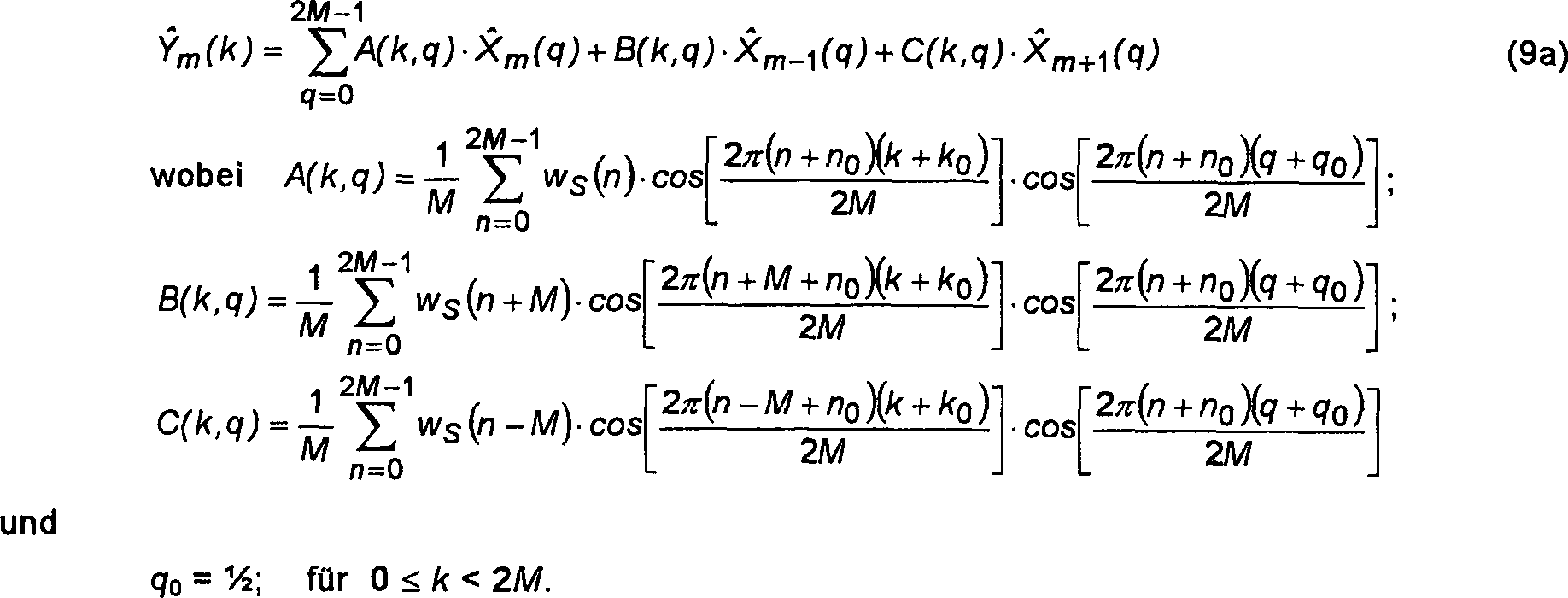
Die Synthesetransformation ![]()
![]()
![]()
![]()
Mit Überlapp-Summieren ![]()
![]()
ws(n) =
Synthesefensterfunktion im Punkt n.With overlap totalizing ![]()
![]()
w s (n) = synthesis window function at point n.
In den Ausführungsbeispielen mit TDAC-Transformation sollten die Analyse- und Synthesefensterfunktionen so ausgewählt werden, daß sie jenen Einschränkungen Genüge tun, die erforderlich sind, um eine Alias-Löschung zu erzielen. Hierzu wird auf die oben zitierte Veröffentlichung von Princen verwiesen. Zusätzliche Informationen zu Analyse- und Synthesefensterfunktionen sind aus dem US Patent 5 222 189 und der am 17. Oktober 1998 eingereichten internationalen Patentanmeldung Nummer PCT/US 98/20751 zu entnehmen.In the exemplary embodiments with TDAC transformation the analysis and synthesis window functions should be selected so that she those restrictions enough to do alias deletion. For this will refer to the publication cited above directed by Princen. additional Information about analysis and synthesis window functions is off U.S. Patent 5,222,189 and that filed on October 17, 1998 international patent application number PCT / US 98/20751.
Die Bank der Analysefilter ![]()
![]()
![]()
![]()
Wenn in dem der Synthesetransformation ![]()
![]()
Die hypothetische Wiedergabe in der
Frequenzdomäne,
die vom Analysefilter ![]()
![]()
2. Erneute Benennung der Quantisierungsaufgabe2. Renaming the Quantisierungsaufgabe
Unter Heranziehung dieser beiden
hypothetischen Wiedergaben in der Frequenzdomäne, die vom Analysefilter ![]()
N(k) = ein gewünschter
Rauschpegel für
den Transformationskoeffizienten k.Using these two hypothetical renditions in the frequency domain provided by the analysis filter ![]()
N (k) = a desired noise level for the transformation coefficient k.
Für das Quantisierungsrauschen werden folgende Annahmen getroffen:
- 1. Das Quantisierungsrauschen lm(k) für die verschiedenen Transformationskoeffizienten k sind statistisch unabhängig.
- 2. Das Quantisierungsrauschen lm(k) für verschiedene Koeffizientenblöcke m sind statistisch unabhängig.
- 3. Das Quantisierungsrauschen lm(k) in einem jeweiligen Koeffizientblock m haben einen Mittelwert, der Null gleicht, und haben Abweichungen, die in aufeinanderfolgenden Koeffizientenblöcken gleich sind.
- 1. The quantization noise l m (k) for the different transformation coefficients k are statistically independent.
- 2. The quantization noise l m (k) for different coefficient blocks m are statistically independent.
- 3. The quantization noise l m (k) in a respective coefficient block m have an average value that is equal to zero and have deviations that are the same in successive coefficient blocks.
Die ersten beiden Annahmen treffen zu für die Koeffizienten, die von den allgemein in Tonkodiersystemen verwendeten Transformationen erhalten werden. Die dritte Annahme trifft zu für Blöcke von Transformationskoeffizienten, die ein stationäres Signal wiedergeben, und sie ist gerechtfertigt für quasi stationäre Passagen von Musik, die mit bekannten perzeptuellen Kodiersystemen und Verfahren nicht gut zu quantisieren sind. Bei stark nichtstationären Passagen, für die die dritte Annahme nicht gerechtfertigt ist, sind durch diese Annahme verursachte Fehler insgesamt gutartig und können ignoriert werden.Make the first two assumptions too for the coefficients used by those commonly used in sound coding systems Transformations are obtained. The third assumption applies to blocks of Transform coefficients representing a stationary signal, and it is justified for quasi stationary Passages of music using well-known perceptual coding systems and methods are not easy to quantify. In the case of highly non-stationary passages, for the The third assumption is not justified by this assumption errors caused are generally benign and can be ignored.
3. Streumatrix3. Litter matrix
Ein Prozeß zum Quantisieren, der die Ausbreitung des Synthesefilterrauschens ordnungsgemäß berücksichtigt, kann aus einem analytischen Ausdruck des Verhältnisses zwischen dem Rausch spektrum des vom Synthesefilter erhaltenen Ausgabesignals und dem Rauschspektrum des dem Synthesefilter bereitgestellten, quantisierten Eingabesignals entwickelt werden. Eine Ableitung dieses analytischen Ausdrucks bzw. der "Streumatrix" soll nunmehr beschrieben werden.A process of quantizing that Spread of synthesis filter noise properly taken into account, can be from an analytical expression of the relationship between the noise spectrum the output signal and the noise spectrum obtained from the synthesis filter of the quantized input signal provided to the synthesis filter be developed. A derivative of this analytical expression or the "scatter matrix" will now be described become.
Zunächst wird der Ausdruck für ![]()
![]()
![]()
![]()
Ein ähnlicher Ausdruck kann für die hypothetische
Wiedergabe in der Frequenzdomäne
des Ausgabesignals des Synthesefilters, ausgedrückt als nicht quantisierte
Transformationskoeffizienten, erhalten werden, indem ein ähnlicher
Ersatz in der Gleichung (7) vorgenommen wird. Der Ausdruck ist wie
folgt: ![]()
![]()
Durch Subtrahieren der Gleichung
(9b) von der Gleichung (9a) kann eine hypothetische Wiedergabe in
der Frequenzdomäne
der Differenz zwischen diesen beiden Ausgabesignalen erhalten werden,
die wie folgt dargestellt werden kann: 
Om(k)
= Quantisierungsrauschen im Synthesefilter-Ausgabesignal bei der
Frequenz k und
lm(k) = ![]()
O m (k) = quantization noise in the synthesis filter output signal at the frequency k and
l m (k) = ![]()
Der Ausdruck in der Gleichung (10)
kann benutzt werden, um den Ausdruck (
![]()
![]()
Die Matrices A, B und C haben eine
ungerade Symmetrie. Diese Eigenschaften können benutzt werden, um zu
zeigen, daß: ![]()
![]()
A'(k,q) = 2A(k,q);
B'(k,q) = 2B(k,q) ;
und
C'(k,q)
= 2C(k,q).The matrices A, B and C have an odd symmetry. These properties can be used to show that: ![]()
![]()
A '(k, q) = 2A (k, q);
B '(k, q) = 2B (k, q); and
C '(k, q) = 2C (k, q).
Unter den drei zuvor erwähnten Annahmen,
daß die
Komponenten des Quantisierungsrauschens einen Null-Mittelwert haben,
statistisch unabhängig
und identisch verteilt sind, kann das Rauschleistungsspektrum am
Ausgang der Synthesefilter aus der Gleichung (13) wie folgt erhalten
werden: 
E(z) = der erwartete
Wert von z;
N0m(k) Rauschleistung bei
Frequenz k im Ausgang der Synthesefilter;
E (z) = the expected value of z;
N 0m (k) noise power at frequency k in the output of the synthesis filter;
Unter der dritten, oben genannten
Annahme, daß die
Quantisierungsrauschabweichung in aufeinanderfolgenden Koeffizientenblöcken identisch
ist, kann die Gleichung (14) wie folgt vereinfacht werden: ![]()
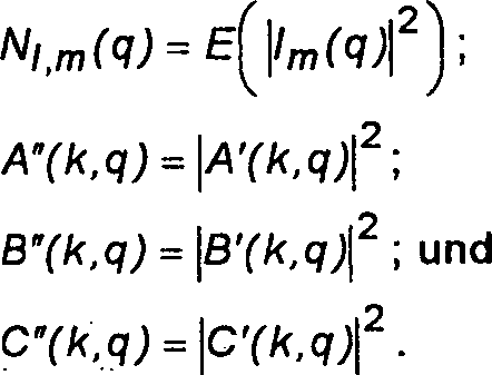
W(k,q) = A''(k,q) + B''(k,q)
+ C''(k,q). Die W-Matrix
ist die oben erwähnte
Streumatrix.Assuming the third assumption mentioned above that the quantization noise deviation is identical in successive coefficient blocks, equation (14) can be simplified as follows: ![]()
W (k, q) = A '' (k, q) + B '' (k, q) + C '' (k, q). The W matrix is the scatter matrix mentioned above.
4. Optimale Quantisierungsauflösung4. Optimal quantization
Unter Hinweis auf die Ausdrücke (![]()
![]()
Für
Gleichheit mit dem gewünschten
Rauschen ist eine direkte Lösung: ![]()
![]()
Leider ergibt diese direkte Lösung häufig negative
Lösungen
für einen
oder mehr Transformationskoeffizienten k, und das heißt, daß die Neigung
des gewünschten
Rauschpegels N(k) so steil ist, daß negative Rauschmengen in
den Quantisierungsprozeß injiziert
werden müssen,
um die spektrale Gestalt des gewünschten
Rauschens zu erzielen. In Ausführungsbeispielen
in der Praxis ist es nicht möglich,
negative Mengen an Rauschen in den Quantisierungsprozeß zu injizieren.
Glücklicherweise
braucht für
die Gleichheit der Ausdruck (
Um eine Lösung zu erzielen, kann das
Quantisierungsrauschspektrum, ausgedrückt als gewünschtes Rauschspektrum, wie
folgt neu geschrieben werden ![]()
![]()
a) Zweidimensionales Beispiela) Two-dimensional example
Um die Darstellung zu erleichtern,
wird ein zweidimensionales Beispiel (M=2) benutzt, um zu erklären, wie
die Verstärkungsfaktoren
angewandt werden können.
Durch Einsetzen der Gleichung (18) in den Ausdruck (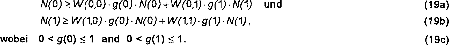
Auch wenn g(0) = g(1) = 0 immer die beiden Ungleichheiten erfüllt, ist diese spezielle Lösung deshalb nicht akzeptabel, weil jeder Null-Wert des Verstärkungsfaktors impliziert, daß der jeweilige Transformationskoeffizient mit unendlicher Präzision quantisiert werden muß. Bevorzugte Lösungen ergeben Werte für die Verstärkungsfaktoren, die so nahe wie möglich bei eins liegen. Wenn eine Lösung gefunden werden kann, bei der alle Verstärkungsfaktoren einen Wert von eins haben, ist es tatsächlich so, daß für die Synthesefilter-Rauschausbreitung kein Ausgleich nötig ist.Even if g (0) = g (1) = 0 always the fulfilled both inequalities, is this special solution not acceptable because any zero value of the gain implies that the respective transformation coefficient quantized with infinite precision must become. Preferred solutions give values for the gain factors, the as close as possible be at one. If a solution can be found in which all gain factors have a value of actually have one so that for the synthesis filter noise propagation no compensation necessary is.
Die Suche nach Verstärkungsfaktorwerten, die eine optimale Lösung bieten, kann man als eine linear eingegrenzte Optimierungsaufgabe umreißen, die darauf abgestellt ist, die Kosten des Ausgleichs auf ein Minimum zu senken. In vielen Ausführungsbeispielen ist es zweckmäßig, die Ausgleichskosten als Logarithmus des Maßes zu erhöhen, um welches das Quantisierungsrauschspektrum verringert wird. Bei einem bevorzugten Ausführungsbeispiel, welches mit Bit-Allocation zum Steuern der Quantisierungsauflösung arbeitet, gleichen die Kosten einem Bit pro Transformationskoeffizient für jede –6.02 dB, um die das Quantisierungsrauschspektrum geändert wird. Wenn zum Beispiel der Verstärkungsfaktor g(1) auf 0,25 gesetzt wird, wird Nl,m(1) des Quantisierungsrauschspektrums um –12.04 dB gegenüber N(1) des gewünschten Rauschspektrums geändert. Die Kosten für diesen Ausgleich der Streuung des Rauschens des Transformationskoeffizienten X(1) beträgt (–12.04 dB / –6.02 dB) = 2 Bit.The search for gain values that offer an optimal solution can be outlined as a linearly narrowed optimization task that aims to minimize the cost of compensation. In many exemplary embodiments, it is expedient to increase the compensation costs as the logarithm of the amount by which the quantization noise spectrum is reduced. In a preferred embodiment that uses bit allocation to control the quantization resolution, the cost is one bit per transform coefficient for every -6.02 dB by which the quantization noise spectrum is changed. For example, if the gain factor g (1) is set to 0.25, N 1, m (1) of the quantization noise spectrum is changed by -12.04 dB compared to N (1) of the desired noise spectrum. The cost of this compensation for the spread of the noise of the transformation coefficient X (1) is (-12.04 dB / -6.02 dB) = 2 bits.
Für
Ausführungsbeispiele
wie die soeben beschriebenen, die eine logarithmische Kostenfunktion
haben, kann das in Gleichung (18) gezeigte, gewünschte Spektrum des Quantisierungsrauschens
zweckmäßigerweise
wie folgt dargestellt werden: ![]()
![]()
Die Ausgleichskosten ändern sich
umgekehrt mit dem Logarithmus jedes Verstärkungsfaktors. So sind die
Gesamtausgleichskosten in diesem zweidimensionalen Beispiel proportional
zu –log
g(0) –log
g(1). Um die Erörterung
zu erleichtern, wird hierbei von einer Proportionalitätskonstante
ausgegangen, die eins ist. Ziel der Optimierungsaufgabe ist es,
die Ausgleichskosten im Rahmen der durch die Ausdrücke (
Der erste Schritt im Formulieren
der Quantisierung als lineare Optimierungsaufgabe besteht darin,
jeden N(j) '' W(i,j) Term in den
Ausdrücken
(
Die auf diese Weise ausgedrückte Optimierungsaufgabe
kann geometrisch in einem g(0), g(1) Koordinatenraum dargestellt
werden, wie
Wenn der Lösungsraum die (1,1) Koordinate
einschließt,
wird die optimale Quantisierungsauflösung erhalten, wenn alle Verstärkungsfaktoren
auf eins gesetzt werden, da kein Ausgleich für Synthesefilter-Rauschausbreitung
erforderlich ist. Unter Hinweis auf
Der optimale Satz Verstärkungsfaktoren
minimiert die Kosten für
den Ausgleich K, die mit folgender Gleichung berechnet werden: ![]()
![]()
Diese Gleichung bestimmt eine hyperbolische
Linie im g(0), g(1) Koordinatenraum und stellt einen Ort von Werten
für die
beiden Verstärkungsfaktoren
dar, die konstanten Kosten K für
den Ausgleich der Rauschausbreitung entsprechen. Eine hyperbelförmige Linie
Wie schon erwähnt, ist es Ziel der Optimierungsaufgabe,
eine Mindestkostenlösung
zu finden, welche die Ausdrücke
(
b) Höhere Dimensionenb) Higher dimensions
In der Praxis arbeiten perzeptuelle
Kodiersysteme und Verfahren mit Filtern, für die es nötig ist, daß der Quantisierungsprozeß eine Optimierungsaufgabe
löst, die
erheblich mehr Dimensionen als zwei umfaßt. Man kann sagen, daß diese
Aufgabe darin besteht, einen Satz Verstärkungsfaktoren {g(k)} innerhalb
des Lösungsraums
zu finden, der die Ungleichheiten: ![]()
![]()
![]()
![]()
![]()
![]()
Wenn zum Beispiel eine TDAC-Transformation der Länge 256 benutzt wird, hat die Optimierungsaufgabe M=128 Dimensionen. Bei diesem Beispiel ist der Bereich möglicher Lösungen auf einen kdimensionalen Würfel beschränkt, der Scheitel mit Koordinaten hat, die Verstärkungsfaktoren entsprechen, deren Werte entweder Null oder Eins sind. Der Lösungsraum für die Optimierungsaufgabe ist derjenige Teil des k-dimensionalen Würfels, der sich zwischen den Koordinatenachsen. und den dem Ursprung am nächsten liegenden Hyperebenen befindet. Die optimale Mindestkostenlösung findet sich am Tangentialpunkt zwischen einer hyperbelförmigen Konstantkosten-Hyperoberfläche und der Grenze des Lösungsraums.For example, if a TDAC transformation the length 256 is used, the optimization task has M = 128 dimensions. In this example, the range of possible solutions is limited to a k-dimensional cube, the Has vertices with coordinates corresponding to gain factors, whose values are either zero or one. The solution space for the optimization task is the part of the k-dimensional cube that lies between the Coordinate axes. and the hyperplanes closest to the origin located. The optimal minimum cost solution can be found at the tangential point between a hyperbolic Constant cost-hypersurface and the boundary of the solution space.
Ein im wesentlichen optimaler Satz
Quantisierungsauflösungen
kann in einem reiterativen Prozeß erhalten werden, beispielsweise
dem in
Es kann im wesentlichen jeder beliebige Satz anfänglicher Quantisierungsauflösungen verwendet werden; aber die Verarbeitungsleistung wird insgesamt verbessert, wenn man anfängliche Auflösungen wählt, die den optimalen Werten nahe sind. Eine zweckmäßige Wahl für die anfänglichen Auflösungen sind diejenigen Auflösungen, die den gewünschten Rauschpegeln entsprechen.It can be essentially any Sentence initial quantization be used; but the processing power is total improved when you start resolutions chooses that are close to the optimal values. A convenient choice for the initial resolutions are those resolutions, the one you want Correspond to noise levels.
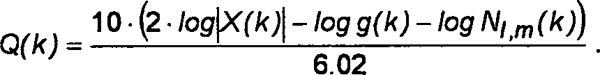
Ein Quantisierungsprozeß kann mittels eines Bitzuordnungsprozesses durchgeführt werden, der folgende Schritte umfaßt:
- 1. Durch Berechnen der gewünschten Rauschleistung für jeden
Transformationskoeffizienten mittels der Gleichung (17) wird eine
unverbindliche Bitzuordnung bestimmt. Die unverbindliche Bitzuordnung
Q(k) für jeden
Transformationskoeffizienten X(k) wird vom Logarithmus der Signalleistung
und dem negativen Logarithmus des jeweils gewünschten Rauschleistungspegels
erhalten. In einem Ausführungsbeispiel
ist die Bitzuordnung beispielsweise

- 2. Wenn die unverbindliche Bitzuordnung für alle Koeffizienten positiv ist, ist der Bitzuordnungsprozeß vollendet, und die Transformationskoeffizienten werden entsprechend den unverbindlichen Bitzuordnungen quantisiert, weil kein Ausgleich für die Streuung des Rauschens durch Synthesefilter nötig ist.
- 3. Wenn die aus dem ersten Schritt erhaltene unverbindliche
Bitzuordnung für
irgendeinen Transformationskoeffizienten negativ ist, wird es erforderlich,
die Ausbreitung des Rauschens auszugleichen. Der Bitzuordnungsprozeß wird fortgesetzt,
indem der k-dimensionale Einheitswürfel gemäß dem Ausdruck (
24 ) bestimmt wird. - 4. Im Hyperraum sind die Überschneidungen
derjenigen Bereiche zu finden, welche die Ungleichheiten des Ausdrucks
(
23 ) erfüllen. Das kann wirksamer geschehen, wenn lediglich die Hyperebenen eingeschlossen werden, welche durch die Reihen in der Matrix D bestimmt sind, die dem Ursprung am nächsten liegen. Der Abstand d für jede Hyperebene kann bestimmt werden ausEine Hyperebene kann dem Ursprung in einem Teil des Hyperraums am nächsten liegen, und eine oder mehr andere Hyperebenen können dem Ursprung in anderen Teilen des Hyperraums am nächsten liegen.
- 5. Aus der Überschneidung des im Schritt 3 bestimmten k-dimensionalen Würfels und der Überschneidung von im Schritt 4 gefundenen Bereichen wird der Lösungshyperraum bestimmt.
- 6. Es werden anfängliche Ausgleichskosten K ausgewählt.
- 7. Es wird bestimmt, ob die hyperbelförmige Hyperoberfläche der Konstantkosten für die Kosten K den im Schritt 5 bestimmten Lösungshyperraum schneidet.
- 8. Wenn die hyperbelförmige
Hyperoberfläche
für die
Kosten K zur Grenze des Lösungshyperraums
eine Tangente bildet, ist die Bitzuordnung abgeschlossen. Die Anzahl
zusätzlicher
Bits, die für
jeden Transformationskoeffizienten X(k) erforderlich sind, um einen
optimalen Ausgleich für
die Rauschausbreitung zu schaffen, wird vom negativen Logarithmus
des jeweiligen Verstärkungsfaktors
erhalten. Bei einem Ausführungsbeispiel
ist die Bitzuordnung für
jeden Koeffizienten beispielsweise
- 9. Wenn die hyperbelförmige Hyperoberfläche den Lösungshyperraum nicht schneidet, sind Kosten auszuwählen, die höher sind als die laufenden Kosten K und es ist mit dem Schritt 7 fortzufahren.
- 10. Wenn die hyperbelförmige Hyperoberfläche den Lösungshyperraum schneidet, sind Kosten auszuwählen, die niedriger sind als die laufenden Kosten K, und es ist mit dem Schritt 7 fortzufahren.
- 1. A non-binding bit allocation is determined by calculating the desired noise power for each transformation coefficient using equation (17). The non-binding bit allocation Q (k) for each transformation coefficient X (k) is obtained from the logarithm of the signal power and the negative logarithm of the desired noise power level. In one embodiment, the bit allocation is, for example
- 2. If the non-binding bit allocation is positive for all coefficients, the bit allocation process is complete and the transform coefficients are quantized according to the non-binding bit allocations because no compensation for the noise spread by synthesis filters is necessary.
- 3. If the non-binding bit allocation obtained from the first step is negative for any transformation coefficient, it will be necessary to compensate for the spread of the noise. The bit allocation process is continued by the k-dimensional unit cube according to the expression (
24 ) is determined. - 4. In hyperspace, the overlaps of those areas can be found which
23 ) fulfill. This can be done more effectively if only the hyperplanes that are determined by the rows in the matrix D that are closest to the origin are included. The distance d for each hyperplane can be determined fromA hyperplane may be closest to the origin in one part of the hyperspace, and one or more other hyperplanes may be closest to the origin in other parts of the hyperspace. - 5. The solution hyperspace is determined from the overlap of the k-dimensional cube determined in step 3 and the overlap of areas found in step 4.
- 6. Initial compensation costs K are selected.
- 7. It is determined whether the hyperbolic hyper surface of the constant costs for the costs K intersects the solution hyperspace determined in step 5.
- 8. If the hyperbolic hyper surface forms a tangent to the cost K to the boundary of the solution hyperspace, the bit assignment is complete. The number of additional bits required for each transformation coefficient X (k) in order to optimally compensate for the noise propagation is obtained from the negative logarithm of the respective gain factor. In one embodiment, the bit allocation for each coefficient is, for example
- 9. If the hyperbolic hyper surface does not intersect the solution hyperspace, select costs that are higher than the running costs K and continue with step 7.
- 10. If the hyperbolic hyperface intersects the solution hyperspace, select costs that are less than the running costs K and proceed to step 7.
D. Vereinfachte ProzesseD. Simplified processes
Um den vorstehend beschriebenen Optimierungsprozeß durchzuführen, sind beträchtliche Rechnerressourcen erforderlich. In manchen Anwendungsfällen sind die Kosten für die Bereitstellung dieser Rechnerressourcen zu groß, und deshalb sind für diese Anwendungsfälle vereinfachte Prozesse wünschenswert, die Annäherungen an die optimale Lösung bieten. Es sollen nun einige Ausführungsbeispiele vereinfachter Prozesse beschrieben werden, in denen die Bitzuordnung zum Steuern der Quantisierungsauflösung verwendet wird. In jedem dieser Prozesse wird davon ausgegangen, daß eine anfängliche Bitzuordnung für jeden Transformationskoeffizienten unbeachtlich eines Ausgleichs für die Rauschausbreitung durch Synthesefilter in dem Bemühen festgelegt wurde, ein Quantisierungsrauschspektrum zu erhalten, das dem gewünschten Rauschspektrum im wesentlichen gleicht. Ausgehend von dieser anfänglichen Bitzuordnung werden in jedem Prozeß diejenigen Transformationskoeffizienten identifiziert, deren Bitzuordnungen erhöht werden sollten, um die gewünschten Rauschpegel zu erzielen.Considerable computing resources are required to perform the optimization process described above. In some use cases, the cost of providing these computing resources is too great, and therefore simplified processes are desirable for these use cases Offer approximations to the optimal solution. Some embodiments of simplified processes in which bit allocation is used to control the quantization resolution will now be described. In each of these processes, it is assumed that an initial bit allocation for each transform coefficient was set irrespective of compensation for noise propagation through synthesis filters in an effort to obtain a quantization noise spectrum that is substantially the same as the desired noise spectrum. On the basis of this initial bit allocation, those transformation coefficients whose bit allocations should be increased in order to achieve the desired noise levels are identified in each process.
1. Erster vereinfachter Prozeß1. First simplified process
In einem ersten vereinfachten Prozeß wird eine metrische Funktion zum Schätzen des Gesamtrauschpegels für jeden Transformationskoeffizienten X(k) einzeln, beginnend mit dem Transformationskoeffizienten der niedrigsten Frequenz X(0) benutzt und bestimmt, ob die Rauschausbreitung dazu führt, daß das Gesamtrauschen für diesen Koeffizienten den gewünschten Rauschpegel N(k) überschreitet. Wenn die Schätzung anzeigt, daß der Gesamtrauschpegel für den laufenden Koeffizienten X(k) den gewünschten Rauschpegel nicht überschreitet, wird der Prozeß mit dem Transformationskoeffizienten der nächst höheren Frequenz fortgesetzt.In a first simplified process, a metric function for estimating of the total noise level for each transformation coefficient X (k) individually, starting with the Lowest frequency transform coefficients X (0) used and determines whether the noise propagation results in the total noise for it Coefficients the desired Noise level exceeds N (k). If the estimate indicates that the Total noise level for the running coefficient X (k) does not exceed the desired noise level, is the process with the transformation coefficient of the next higher frequency continued.
Wenn die Schätzung zeigt, daß der Gesamtrauschpegel für den laufenden Koeffizienten X(k) den gewünschten Rauschpegel N(k) übersteigt, wird derjenige Koeffizient bestimmt, der den größten Beitrag zum Rauschpegel des Koeffizienten X(k) liefert, und der Verstärkungsfaktor g(k) für diesen Koeffizienten wird auf einen vorgeschriebenen Wert, zum Beispiel –144 dB gesetzt, der bei einem Ausführungsbeispiel einen Ausgleich von 24 Bit wiedergibt. Die metrische Funktion wird benutzt, um den Gesamtrauschpegel für den Koeffizienten X(k) zu schätzen, der das Resultat der variierten Bitzuordnung ist. Wenn der geschätzte Rauschpegel immer noch den gewünschten Rauschpegel N(k) überschreitet, wird derjenige Koeffizient identifiziert, der den größten Beitrag zum Rauschpegel des Koeffizienten X(k) leistet, dessen Verstärkungsfaktor wird auf den vorgeschriebenen Wert gesetzt, und dann wird die metrische Funktion erneut benutzt, um den neuen Rauschpegel zu schätzen. Dies wird fortgesetzt, bis der geschätzte Rauschpegel auf ein Niveau reduziert ist, welches dem gewünschten Rauschpegel gleicht oder unterhalb desselben liegt.If the estimate shows that the total noise level for the current coefficient X (k) exceeds the desired noise level N (k), the coefficient that makes the greatest contribution to the noise level is determined of the coefficient X (k), and the gain factor g (k) for it Coefficients are set to a prescribed value, for example –144 dB set that in one embodiment represents a 24 bit offset. The metric function is used to increase the total noise level for the coefficient X (k) estimate, which is the result of the varied bit allocation. If the estimated noise level always still the one you want Noise level exceeds N (k), the coefficient that makes the greatest contribution is identified to the noise level of the coefficient X (k), its gain factor is set to the prescribed value, and then the metric Function used again to estimate the new noise level. This continues until the estimated Noise level is reduced to a level that meets the desired Noise level is equal to or below it.
In diesem Punkt besteht ein Satz {S} Koeffizienten, deren Verstärkungsfaktoren auf den vorgeschriebenen Wert gesetzt wurden, um den geschätzten Rauschpegel für den Koeffizienten X(k) zu verringern. Die Verstärkungsfaktoren für die Koeffizienten im Satz {S} werden entsprechend einer Formel variiert, um das zu bekommen, von dem erwartet wird, daß es gerade genügend Ausgleich für die Streuung des Rauschens erbringt. Der Bitzuordnungsprozeß wird dann mit dem Transformationskoeffizienten der nächsthöheren Frequenz fortgesetzt.There is a sentence on this point {S} coefficients, their gain factors were set to the prescribed value to the estimated noise level for the To reduce coefficients X (k). The gain factors for the coefficients in the sentence {S} are varied according to a formula to get that, which is expected to be just enough Compensation for spreads the noise. The bit allocation process then continued with the transform coefficient of the next higher frequency.
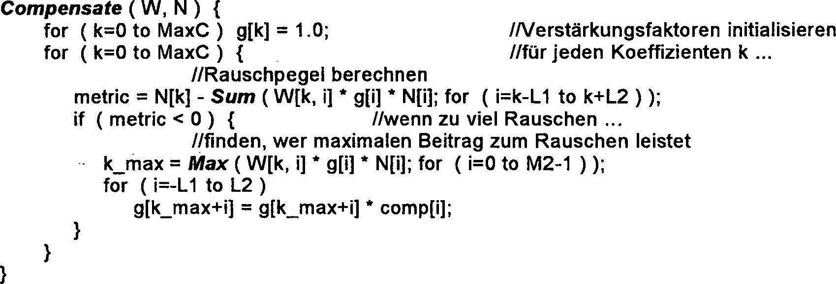
Ein Ausführungsbeispiel, mit dem der erste vereinfachte Prozeß verwirklicht wird, ist im folgenden Programmfragment gezeigt. Dieses Programmfragment ist in einem Pseudocode ausgedrückt, der eine Syntax verwendet, die einige Syntaxmerkmale der C, FORTRAN und BASIC Programmiersprachen umfaßt. Dieses Programmfragment und weitere hier beschriebene Programmfragmente sind nicht als zur Kompilierung geeignete Quellcodesegmente gedacht, sondern werden lediglich angegeben, um einige Aspekte möglicher Verwirklichungen zu vermitteln.An embodiment with which the first simplified process realized is shown in the following program fragment. This program fragment is expressed in a pseudo code, that uses a syntax that has some syntax features of the C, FORTRAN and BASIC programming languages. This program fragment and other program fragments described here are not considered to be Compile suitable source code segments, but are thought merely stated to some aspects of possible realizations convey.

Die Routine Compensate ist mit einer Matrix W versehen, bei der es sich um die Streumatrix für eine Synthesefilterbank handelt, und mit einer Matrix N, welche das gewünschte Rauschspektrum spezifiziert. Verstärkungsfaktoren in der Matrix g werden auf einen Wert 1 0 für die interessierenden niederfrequenten Koeffizienten von k=0 bis hinauf zu k=MaxC initialisiert. Für die Koeffizienten mit den höchsten Frequenzen ist bei vielen Ausführungsbeispielen kein Ausgleich erforderlich.The routine Compensate is with one Provide matrix W, which is the scattering matrix for a synthesis filter bank and with a matrix N, which specifies the desired noise spectrum. gains in the matrix g to a value 1 0 for the low-frequency of interest Initialized coefficients from k = 0 up to k = MaxC. For the coefficients with the highest Frequencies is in many embodiments no compensation required.
Eine Haupt-for-Schleife bildet den
Rest der Routine Compensate und führt den Ausgleichsprozeß für jeden
der interessierenden niederfrequenten Koeffizienten durch. Die Null
Funktion wird aufgerufen, um eine Matrix S in einen Leer- oder Nullzustand
zu initialisieren. Der Variablen metric wird eine Schätzung für den Rauschpegel
des laufenden Koeffizienten k durch Aufrufen der Funktion Sum zugeteilt,
um die Summe ![]()
![]()
Die Grenzen L1 und L2 der Summierung haben einen signifikanten Einfluß auf die Rechenkomplexität dieses Prozesses; die Größenordnung der Komplexität für die Routine Compensate ist (L1+L2)2. Der Rechenwirkungsgrad kann durch Einstellen der Werte L1 und L2, so daß der in die Berechnung eingeschlossene Umfang an Koeffizienten begrenzt wird, verbessert werden. Der Wert für diese Grenzen kann empirisch bestimmt werden. Bei einem nachfolgend beschriebenen anderen vereinfachten Prozeß entsprechen diese Grenzen dem Bereich von Nichtnullelementen in einer Version mit dünn besiedeltem Feld der Matrix W.The limits L1 and L2 of the summation have a significant influence on the computational complexity of this process; the magnitude of complexity for the routine compensate is (L1 + L2) 2 . The calculation efficiency can be improved by setting the values L1 and L2 so that the range of coefficients included in the calculation is limited. The value for these limits can be determined empirically. In another simplified process described below, these limits correspond to the range of non-zero elements in a sparsely populated field version of the matrix W.
Wenn der geschätzte Rauschpegel geringer ist als der gewünschte Rauschpegel ist metric positiv und kein Ausgleich für eine Streuung des Rauschens nötig. Wenn also metric positiv ist, wird der Rest der for-Schleife übersprungen, und die Verarbeitung wird für den nächsten Koeffizienten fortgesetzt.When the estimated noise level is lower than the one you want Noise level is metric positive and does not compensate for scatter of noise is necessary. So if metric is positive, the rest of the for loop is skipped, and processing is for the next Coefficients continued.
Wenn metric negativ ist, wird die Verarbeitung mit einer while-Schleife fortgesetzt, die so lange weitergeführt wird, bis metric positiv wird. Noch innerhalb dieser while-Schleife wird die Funktion Max aufgerufen, um den Koeffizienten k_max zu bestimmen, der den größten Beitrag zum Rauschen für den Koeffizienten k leistet. Das geschieht dadurch, daß der Index i gefunden wird, der dem maximalen Wert für das Produkt W[k,i]*g[i]*N[i] für i von 0 bis M2-1 entspricht. Dieser Bereich für den Index i schließt alle Transformationskoeffizienten für das System ein. Wenn gewünscht, kann der Verarbeitungswirkungsgrad dadurch verbessert werden, daß die Suche nach dem maximalen Produkt auf einen engeren Koeffizientenbereich begrenzt wird. Dieser Bereich kann empirisch bestimmt werden. Wenn der Koeffizient gefunden wurde, der den größten Beitrag leistet, wird dem Verstärkungsfaktor für k_max ein vorgeschriebener Wert max.correction zugeteilt, der irgendeinem maximalen Ausmaß an Ausgleich entspricht. Bei einem Ausführungsbeispiel ist dieses maximale Ausmaß für den Ausgleich –144 dB, was 24 Bit entspricht. Nach dem Aufruf der Funktion Union, um der Matrix S k.max hinzuzufügen, wird eine Schätzung des Rauschpegels berechnet, wozu wiederum der revidierte Verstärkungsfaktor für k.max herangezogen wird, und wird dann der variablen metric zugeschrieben. Die while-Schleife wird fortgesetzt, bis der Wert für metric positiv wird.If metric is negative, the Processing continued with a while loop for as long continued until metric becomes positive. Still within this while loop the function Max is called to get the coefficient k_max determine who makes the greatest contribution to the noise for performs the coefficient k. This happens because the index i is found, which is the maximum value for the product W [k, i] * g [i] * N [i] for i of Corresponds to 0 to M2-1. This area for index i closes all Transform coefficients for the system. If desired, The processing efficiency can be improved by making the search after the maximum product to a narrower coefficient range is limited. This area can be determined empirically. If the coefficient that makes the greatest contribution has been found the gain factor for k_max a prescribed max.correction value assigned to any maximum extent Compensation corresponds. In one embodiment, this is maximum Level of compensation –144 dB, which corresponds to 24 bits. After calling the function Union to the Add matrix S k.max, becomes an estimate of the noise level, which in turn is the revised gain factor for k.max is used, and is then attributed to the variable metric. The while loop continues until the value for metric becomes positive.
Wenn ein Ausgleich auf ausreichend
viele der maximale Beiträge
leistenden Koeffizienten angewandt wurde, wird der geschätzte Rauschpegel
für den
Koeffizienten k auf einen Wert herabgesetzt, der kleiner ist als
der gewünschte
Rauschpegel N[k] oder diesem gleicht, und die Variable metric wird
positiv. Wenn das geschieht, endet die while-Schleife und die Verarbeitung
wird fortgesetzt mit dem Aufrufen der Funktion Adjust, um einen
unverbindlichen neuen Wert g.new für die Verstärkungsfaktoren der in der Matrix
S vertretenen Koeffizienten zu berechnen, die den Koeffizienten
im oben beschriebenen Satz {S} entsprechen. Diese neuen Werte sollen
das Ausgleichsniveau optimieren, so daß der geschätzte Rauschpegel im wesentlichen
dem gewünschten
Rauschpegel entspricht. Das läßt sich
erreichen mittels der folgenden Berechnung: ![]()
![]()
Jeder Verstärkungsfaktor für die in der Matrix S dargestellten Koeffizienten wird auf den unverbindlichen Wert g.new gesetzt, wenn der unverbindliche Wert geringer ist als der laufende Wert des jeweiligen Verstärkungsfaktors.Any gain factor for the in the coefficient S shown is based on the non-binding Value g.new set if the non-binding value is less than the current value of the respective gain factor.
Die Haupt-for-Schleife im Ausgleichsprozeß wird mit dem nächsten Transformationskoeftizienten fortgesetzt, bis alle interessierenden Koeffizienten verarbeitet worden sind.The main for loop in the equalization process is with the next Transformation coefficients continued until everyone interested Coefficients have been processed.
2. Abwandlungen des ersten vereinfachten Prozesses2. Variations the first simplified process
Der oben beschriebene erste vereinfachte Prozeß kann auf verschiedene Weise abgewandelt werden, um den Verarbeitungswirkungsgrad zu verbessern. Einige der Möglichkeiten wurden schon kurz oben erwähnt.The first simplified above Process can can be modified in various ways to improve processing efficiency to improve. Some of the ways were mentioned briefly above.
Mit einer Abänderung wird eine signifikante Verringerung der Rechenkomplexität durch das Erkennen der Tatsache erreicht, daß einige Elemente in einer typischen Streumatrix W erheblich größer sind als alle anderen Elemente, und daß eine gute Leistung selbst dann verwirklicht werden kann, wenn viele dieser kleineren Elemente auf Null gesetzt werden.With an amendment it becomes a significant one Reduce computational complexity by recognizing the fact that some elements in one typical scatter matrix W are considerably larger than all other elements, and that one good performance can be achieved even when many of these smaller elements are set to zero.
Mit einer weiteren Abwandlung wird der Verarbeitungswirkungsgrad dadurch verbessert, daß die while-Schleife in dem vorstehend beschriebenen Ausführungsbeispiel entfällt. Der Wirkungsgrad wird dadurch verbessert, daß ein reiterativer Prozeß wegfällt, bei dem der den Hauptbeitrag zum Rauschen leistende Koeffizient bestimmt und ein unverbindlicher neuer Wert für die Verstärkungsfaktoren berechnet wird. Ein Ausführungsbeispiel für diese Abwandlung ist im folgenden Programmfragment gezeigt.With another modification processing efficiency is improved by making the while loop is omitted in the embodiment described above. The Efficiency is improved by eliminating a reiterative process which determines the coefficient making the main contribution to noise and a non-binding new value for the gain factors is calculated. An embodiment for this Modification is shown in the following program fragment.
Bei dieser Abwandlung ist die Routine Compensate mit der Matrix W und der Matrix N wie vorstehend beschrieben versehen. Verstärkungsfaktoren in der Matrix g werden auf einen Wert von 1.0 für die interessierenden niederfrequenten Koeffizienten von k=0 bis hinauf zu k=MaxC initialisiert. Für die Koeffizienten mit den höchsten Frequenzen ist bei vielen Ausführungsbeispielen kein Ausgleich nötig.With this variation is routine Compensate with the matrix W and the matrix N as described above Mistake. gains in the matrix g are set to a value of 1.0 for the low-frequency of interest Initialized coefficients from k = 0 up to k = MaxC. For the coefficients with the highest Frequencies is in many embodiments no compensation necessary.
Die Haupt-for-Schleife bildet den Rest der Routine und führt den Ausgleichsprozeß für jeden der interessierenden niederfrequenten Koeffizienten durch. Der Variablen metric wird ein Wert zugeordnet, der den Rauschpegel für den laufenden Koeffizienten k schätzt, wie vorstehend beschrieben.The main for loop forms the Rest of the routine and leads the equalization process for everyone of the low-frequency coefficients of interest. The variable metric is assigned a value that represents the noise level for the current Coefficient k estimates as described above.
Ist der geschätzte Rauschpegel geringer als der gewünschte Rauschpegel, ist metric positiv und kein Ausgleich für Rauschausbreitung nötig. Wenn also metric positiv ist, wird der Rest der for-Schleife übersprungen, und die Verarbeitung wird für den nächsten Koeffizienten fortgesetzt.If the estimated noise level is less than the desired one Noise level, is metric positive and does not compensate for noise propagation necessary. So if metric is positive, the rest of the for loop is skipped, and processing is for the next Coefficients continued.
Falls metric negativ ist, wird die Bitzuordnung für einen oder mehr Transformationskoeffizienten erhöht, um die Streuung des Rauschens zu berücksichtigen, indem der den größten Beitrag zum geschätzten Rauschen leistende Koeffizient k.max gefunden und der Transformationskoeffizient k. max und einige benachbarte Koeffizienten einem vorherbestimmten Grad an Korrektur unterzogen werden. Der den maximalen Beitrag leistende Koeffizient wird durch Aufrufen der Funktion Max bestimmt, wie oben beschrieben, und die vorherbestimmten Korrekturen werden durch Verringern der Werte der Verstärkungsfaktoren für die Koeffizienten –L1 bis L2 angebracht, indem jeder Verstärkungsfaktor mit einem jeweiligen Wert in der Matrix comp multipliziert wird. So kann zum Beispiel der Verstärkungsfaktor g[k_max] reduziert werden, um eine 2-Bit Zunahme in der Zuordnung anzuzeigen, die Verstärkungsfaktoren g[k_max–1] und g[k_max+1] können reduziert werden, um eine 1,5-Bit Zunahme in der Zuordnung anzuzeigen, und die Verstärkungsfaktoren g[k_max–2] und g[k_max+2] können reduziert werden, um eine 1-Bit Zunahme in der Zuordnung anzuzeigen. Der Grad der im voraus festgelegten Korrektur kann für jede Anwendung empirisch festgelegt werden.If metric is negative, the Bit allocation for one or more transform coefficients increased to the spread of the noise to take into account by making the biggest contribution to the estimated noise performing coefficient k.max found and the transformation coefficient k. max and some neighboring coefficients to a predetermined one Degree of correction. The one who makes the maximum contribution Coefficient is determined by calling the Max function, as above and the predetermined corrections are reduced the values of the gain factors for the Coefficients –L1 to L2 attached by each gain factor with a respective Value in the matrix comp is multiplied. For example the gain factor g [k_max] can be reduced by a 2-bit increase in the allocation indicate the gain factors g [k_max-1] and g [k_max + 1] can reduced to indicate a 1.5-bit increase in the allocation and the gain factors g [k_max-2] and g [k_max + 2] can be reduced to indicate a 1-bit increase in the allocation. The degree of pre-determined correction can vary for each application be determined empirically.
Die Haupt-for-Schleife im Ausgleichsprozeß wird mit dem nächsten Transformationskoeffizienten fortgesetzt, bis alle interessierenden Koeffizienten verarbeitet worden sind.The main for loop in the equalization process is with the next Transformation coefficients continued until all interested Coefficients have been processed.
Ein weiteres Ausführungsbeispiel dieser Abwandlung ist im folgenden Programmfragment gezeigt.Another embodiment of this modification is shown in the following program fragment.

Anders als bei den oben beschriebenen Beispielen sind die Streumatrix, die Verstärkungsfaktoren und die Rauschpegel in Dezibel ausgedrückt, und deshalb wird eine Funktion LogAdd benutzt, um die Summe von zwei logarithmischen Werten zu erhalten. Der Rauschbeitrag des Koeffizienten j zum Koeffizienten k ist durch den Ausdruck w[k][j] + n[j] wiedergegeben, der das Produkt des gewünschten Rauschpegels für den Koeffizienten j mit einem jeweiligen Element der Streumatrix wiedergibt. Jedes Element k der Matrix alloc stellt das gewünschte Quantisierungsrauschen in Dezibel für den Koeffizienten k dar.Different from the ones described above Examples are the scatter matrix, the amplification factors and the noise level expressed in decibels, and therefore a LogAdd function is used to add the sum of two to get logarithmic values. The noise contribution of the coefficient j for the coefficient k is represented by the expression w [k] [j] + n [j], of the product of the desired Noise level for the coefficient j with a respective element of the scatter matrix reproduces. Each element k of the matrix alloc represents the desired quantization noise in decibels for represents the coefficient k.
3. Zweiter vereinfachter Prozeß3. Second simplified process
Ein zweiter vereinfachter Prozeß bietet einen Ausgleich für Rauschausbreitung in zwei Schritten. Im ersten Schritt wird ein Anfangsbetrag des Ausgleichs bestimmt, indem jeder jeweilige Transformationskoeffizient X(k) einzeln, beginnend mit dem Koeffizienten der niedrigsten Frequenz X(O) herangezogen wird, die benachbarten Koeffizienten X(j) identifiziert werden, die individuelle Beiträge zum geschätzten Rauschpegel des jeweiligen Koeffizienten leisten, welche den gewünschten Rauschpegel N(k) für diesen Koeffizienten übersteigen, und das anfängliche Ausmaß des Ausgleichs für jene benachbarten Koeffizienten X(j) bestimmt wird, so daß deren jeweilige individuelle Beiträge auf den gewünschten Rauschpegel verringert werden. Im zweiten Schritt wird der Ausgleich reiterativ verfeinert, um den gesamten Rauschbeitrag für jeden jeweiligen Transformationskoeffizienten auf den gewünschten Rauschpegel zu bringen.A second simplified process offers compensation for Noise propagation in two steps. The first step is a The initial amount of compensation is determined by each transformation coefficient X (k) individually, starting with the lowest frequency coefficient X (O) is used, the neighboring coefficients X (j) are identified be the individual contributions to the estimated Noise level of the respective coefficient, which achieve the desired Noise level N (k) for exceed this coefficient, and the initial Extent of Compensation for those neighboring coefficients X (j) are determined so that their respective individual contributions to the desired one Noise levels can be reduced. The second step is the compensation refined iteratively to the total noise contribution for everyone respective transformation coefficients to the desired Bring noise level.
Ein Ausführungsbeispiel, mit dem dieser zweite vereinfachte Prozeß verwirklicht wird, ist im folgenden Programmfragment gezeigt.An embodiment with which this second simplified process realized is shown in the following program fragment.

Die Routine Compensate ist mit der Matrix W und der Matrix N versehen, wie vorstehend beschrieben. Eine Matrix compN aus Ausgleichswerten wird von der Matrix N gewünschten Rauschens initialisiert und eine Variable compOK wird initialisiert, so daß die folgende while-Schleife mindestens einmal abläuft. Die while-Schleife bildet den Rest der Compensate Routine und führt den Ausgleichsprozeß in zwei Schritten durch. Die Schleife initialisiert zuerst die Variable, so daß die while-Schleife abschließt, wenn nicht im zweiten Schritt ein übermäßiger Pegel Rauschen berechnet wird.The routine Compensate is with the Matrix W and the matrix N provided as described above. A Matrix compN from compensation values is desired by the matrix N. Noise is initialized and a variable compOK is initialized, So that the the following while loop runs at least once. The while loop forms the rest of the compensate routine and do the balancing process in two Steps through. The loop first initializes the variable, So that the while loop completes, unless an excessive level of noise is calculated in the second step becomes.
Der Teil der Routine, der den ersten Schritt durchführt, initialisiert eine Matrix tempN vorläufiger Berechnungen und führt eine for-Schleife durch, in der die Rauschbeiträge zu jedem Koeffizienten k je einer zur Zeit geprüft wird. Nach dem Initialisieren der Variablen k_max und max_contrib auf den Koeffizienten j=0 wird eine verschachtelte for-Schleife benutzt, um den geschätzten Rauschbeitrag W[k,j]·tempN[j] zu berechnen und zu bestimmen, ob es sich dabei um den bisher berechneten maximalen Beitrag handelt. Ist das nicht der Fall, fährt die verschachtelte Schleife mit dem nächsten Koeffizienten j fort. Wenn dieser geschätzte Rauschbeitrag der bisher berechnete größte Pegel ist, werden die Variablen k_max und max_contrib geändert, um auf den laufenden Koeffizienten j zu verweisen. Wenn nachdem die verschachtelte Schleife die Beiträge für alle Koeffizienten geprüft hat, der maximale Rauschbeitrag max_contrib einen gewünschten Rauschpegel N[kj übersteigt, wird das jeweilige Glied der Ausgleichsmatrix compN[k] um den gleichen Betrag geändert, um den der maximale Beitrag den gewünschten Rauschpegel übersteigt. Die Verarbeitung im ersten Schritt setzt sich mit dem nächsten Koeffizienten fort, bis alle Koeffizienten verarbeitet worden sind.The part of the routine that is the first Performing step initializes a matrix of temporary calculations and performs one for loop in which the noise contributions to each coefficient k one checked at a time becomes. After initializing the variables k_max and max_contrib there is a nested for loop on the coefficients j = 0 used to the estimated Noise contribution W [k, j] · tempN [j] to calculate and determine whether it is the previously calculated maximum contribution. If this is not the case, it drives nested loop with the next coefficient j. If this is valued Noise contribution is the highest level calculated so far, the variables changed k_max and max_contrib, to refer to the running coefficient j. If after the nested loop checked the contributions for all the coefficients that maximum noise contribution max_contrib exceeds a desired noise level N [kj, the respective term of the compensation matrix compN [k] is the same Amount changed, by which the maximum contribution exceeds the desired noise level. The processing in the first step continues with the next coefficient until all the coefficients have been processed.
Der Teil der Routine, der den zweiten Schritt durchführt, errechnet eine Schätzung des Gesamtrauschens für jeden Koeffizienten k und vergleicht diese Schätzung mit dem gewünschten Rauschpegel N[k]. Wenn die Schätzung den gewünschten Rauschpegel übersteigt, wird der Ausgleich compN[k] für den jeweiligen Koeffizienten k um den gleichen Betrag verringert, um den der gewünschte Rauschpegel vom geschätzten Gesamtrauschen überschritten wird. Die Variable compOK wird so gesetzt, daß der erste Schritt und der zweite Schritt nochmals durchgeführt wird.The part of the routine that is the second Performing step calculates an estimate of total noise for each coefficient k and compares this estimate with the desired one Noise level N [k]. If the estimate the wished Noise level exceeds the compN [k] compensation for the respective coefficient k is reduced by the same amount, around the one you want Noise level exceeded by total estimated noise becomes. The variable compOK is set so that the first step and the second step performed again becomes.
Die Haupt-while-Schleife setzt sich fort, bis der erste und zweite Schritt durchgeführt werden kann, ohne zu veranlassen, daß die Variable compOK auf "falsch" gesetzt wird.The main while loop continues until the first and second steps can be performed without causing that the Variable compOK is set to "wrong".
Ein alternatives Ausführungsbeispiel, mit dem der zweite vereinfachte Prozeß verwirklicht wird, ist im folgenden Programmfragment gezeigt.An alternative embodiment, with which the second simplified process is implemented is as follows Program fragment shown.

Für die Durchführung dieser Routine sind geringere Rechenressourcen erforderlich, weil die for- Schleife, die den den größten Beitrag leistenden max contrib zum Rauschen für einen gegebenen Koeffizienten j identifiziert, ein schmales Band benachbarter Koeffizienten zu beiden Seiten des Koeffizienten j von j–L1 bis j+L2 prüft, wobei der Koeffizient j selbst ausgeschlossen wird, statt das gesamte Spektrum zu prüfen, wie es mit dem oben beschrieben Programmfragment geschieht.For the implementation This routine requires less computing resources because the for loop, making the greatest contribution performing max contrib to noise for a given coefficient j identifies a narrow band of adjacent coefficients checks both sides of the coefficient j from j-L1 to j + L2, where the coefficient j itself is excluded instead of the whole Spectrum to consider how it happens with the program fragment described above.
E. VerwirklichungE. Realization
Die vorliegende Erfindung kann auf
vielfältigste
Weise verwirklicht werden, einschließlich mittels Software in einem
Universalrechnersystem oder einem sonstigen Gerät, das stärker spezialisierte Bauelemente enthält, beispielsweise
digitale Signalprozessorschaltungen (DSP), die mit Bauelementen ähnlich den
in einem Universalrechnersystem gekoppelt sind.
Bei Ausführungsbeispielen, die in einem Universalrechnersystem verwirklicht sind, können zusätzliche Bauelemente zum Ankoppeln an Geräte, wie eine Tastatur oder Maus und einen Anzeigeschirm eingeschlossen sein, und zum Steuern einer Speichervorrichtung mit Speicherträger, beispielsweise in Form eines Magnetbandes oder einer Magnetplatte oder eines Bildträgers. Der Speicherträger kann zum Aufzeichnen von Anweisungsprogrammen für Betriebssysteme, Dienstprogrammen und Anwendungen benutzt werden und kann Ausführungsbeispiele von Programmen umfassen, mit denen verschiedene Aspekte der vorliegenden Erfindung verwirklicht werden.In embodiments that in one Universal computer system are realized, additional components for coupling on devices, like a keyboard or mouse and a display screen included and to control a storage device with a storage medium, for example in the form of a magnetic tape or a magnetic disk or an image carrier. The storage medium can record instruction programs for operating systems, utilities and applications can be used and can be exemplary embodiments of programs encompass various aspects of the present invention be realized.
Die zum Ausführen verschiedener Aspekte der vorliegenden Erfindung nötigen Funktionen können von Bauelementen durchgeführt werden, die auf verschiedenste Weise verwirklicht sind, einschließlich diskreter logischer Bauelemente, einer oder mehrerer ASIC und/oder programmgesteuerter Prozessoren. Die Art und Weise, in der diese Bauelemente verwirklicht sind, ist für die vorliegende Erfindung nicht wichtig.The functions necessary to carry out various aspects of the present invention can performed by devices that are implemented in a variety of ways, including discrete logic devices, one or more ASIC and / or program-controlled processors. The manner in which these components are implemented is not important for the present invention.
Verwirklichungen der vorliegenden
Erfindung in Form von Software können
mittels einer Vielfalt an maschinenlesbaren Trägern vermittelt werden, beispielsweise
als Basisband oder modulierte Kommunikationswege über das
gesamte Spektrum, einschließlich
von Ultraschall- bis zu Ultraviolettfrequenzen, oder Speichermedien,
einschließlich
solcher, die Informationen im wesentlichen mit Hilfe irgendeiner
magnetischen oder optischen Aufzeichnungstechnik übermitteln,
unter Einschluß von
Magnetbändern,
Magnetplatten und Bildplatten. Verschiedene Aspekte können auch
in verschiedenen Komponenten des Rechnersystems
Claims (19)
Applications Claiming Priority (3)
| Application Number | Priority Date | Filing Date | Title |
|---|---|---|---|
| US09/289,865 US6363338B1 (en) | 1999-04-12 | 1999-04-12 | Quantization in perceptual audio coders with compensation for synthesis filter noise spreading |
| US289865 | 1999-04-12 | ||
| PCT/US2000/009557 WO2000062434A1 (en) | 1999-04-12 | 2000-04-10 | Quantization in perceptual audio coders with compensation for synthesis filter noise spreading |
Publications (2)
| Publication Number | Publication Date |
|---|---|
| DE60004814D1 DE60004814D1 (en) | 2003-10-02 |
| DE60004814T2 true DE60004814T2 (en) | 2004-07-01 |
Family
ID=23113455
Family Applications (1)
| Application Number | Title | Priority Date | Filing Date |
|---|---|---|---|
| DE60004814T Expired - Lifetime DE60004814T2 (en) | 1999-04-12 | 2000-04-10 | QUANTIZATION IN PERCEPTUAL AUDIO ENCODERS WITH COMPENSATION OF NOISE LUBRICATED BY THE SYNTHESIS FILTER |
Country Status (13)
| Country | Link |
|---|---|
| US (1) | US6363338B1 (en) |
| EP (1) | EP1177639B1 (en) |
| JP (1) | JP4643019B2 (en) |
| KR (1) | KR100758215B1 (en) |
| AR (1) | AR024858A1 (en) |
| AT (1) | ATE248463T1 (en) |
| AU (1) | AU771869B2 (en) |
| CA (1) | CA2366560C (en) |
| DE (1) | DE60004814T2 (en) |
| HK (1) | HK1044235B (en) |
| MY (1) | MY120387A (en) |
| TW (1) | TW531986B (en) |
| WO (1) | WO2000062434A1 (en) |
Families Citing this family (50)
| Publication number | Priority date | Publication date | Assignee | Title |
|---|---|---|---|---|
| DE19947877C2 (en) * | 1999-10-05 | 2001-09-13 | Fraunhofer Ges Forschung | Method and device for introducing information into a data stream and method and device for encoding an audio signal |
| US7720651B2 (en) * | 2000-09-29 | 2010-05-18 | Canning Francis X | Compression of interaction data using directional sources and/or testers |
| US7734448B2 (en) * | 2000-01-10 | 2010-06-08 | Canning Francis X | Sparse and efficient block factorization for interaction data |
| TW499672B (en) * | 2000-02-18 | 2002-08-21 | Intervideo Inc | Fast convergence method for bit allocation stage of MPEG audio layer 3 encoders |
| EP1297646B1 (en) * | 2000-06-12 | 2006-04-19 | BRITISH TELECOMMUNICATIONS public limited company | In-service measurement of perceived speech quality by measuring objective error parameters |
| US7945430B2 (en) | 2000-09-29 | 2011-05-17 | Canning Francis X | Compression and compressed inversion of interaction data |
| US7031955B1 (en) * | 2001-04-27 | 2006-04-18 | I2 Technologies Us, Inc. | Optimization using a multi-dimensional data model |
| SE0202159D0 (en) | 2001-07-10 | 2002-07-09 | Coding Technologies Sweden Ab | Efficientand scalable parametric stereo coding for low bitrate applications |
| US6987889B1 (en) | 2001-08-10 | 2006-01-17 | Polycom, Inc. | System and method for dynamic perceptual coding of macroblocks in a video frame |
| US6732071B2 (en) * | 2001-09-27 | 2004-05-04 | Intel Corporation | Method, apparatus, and system for efficient rate control in audio encoding |
| JP3870193B2 (en) | 2001-11-29 | 2007-01-17 | コーディング テクノロジーズ アクチボラゲット | Encoder, decoder, method and computer program used for high frequency reconstruction |
| US7447631B2 (en) * | 2002-06-17 | 2008-11-04 | Dolby Laboratories Licensing Corporation | Audio coding system using spectral hole filling |
| US20040030555A1 (en) * | 2002-08-12 | 2004-02-12 | Oregon Health & Science University | System and method for concatenating acoustic contours for speech synthesis |
| SE0202770D0 (en) * | 2002-09-18 | 2002-09-18 | Coding Technologies Sweden Ab | Method of reduction of aliasing is introduced by spectral envelope adjustment in real-valued filterbanks |
| US7376553B2 (en) * | 2003-07-08 | 2008-05-20 | Robert Patel Quinn | Fractal harmonic overtone mapping of speech and musical sounds |
| WO2005027094A1 (en) * | 2003-09-17 | 2005-03-24 | Beijing E-World Technology Co.,Ltd. | Method and device of multi-resolution vector quantilization for audio encoding and decoding |
| US7539614B2 (en) * | 2003-11-14 | 2009-05-26 | Nxp B.V. | System and method for audio signal processing using different gain factors for voiced and unvoiced phonemes |
| WO2005073959A1 (en) * | 2004-01-28 | 2005-08-11 | Koninklijke Philips Electronics N.V. | Audio signal decoding using complex-valued data |
| DE102004009955B3 (en) * | 2004-03-01 | 2005-08-11 | Fraunhofer-Gesellschaft zur Förderung der angewandten Forschung e.V. | Device for determining quantizer step length for quantizing signal with audio or video information uses longer second step length if second disturbance is smaller than first disturbance or noise threshold hold |
| US7512536B2 (en) * | 2004-05-14 | 2009-03-31 | Texas Instruments Incorporated | Efficient filter bank computation for audio coding |
| US7903137B2 (en) * | 2004-10-15 | 2011-03-08 | Lifesize Communications, Inc. | Videoconferencing echo cancellers |
| US7720236B2 (en) * | 2004-10-15 | 2010-05-18 | Lifesize Communications, Inc. | Updating modeling information based on offline calibration experiments |
| US7760887B2 (en) * | 2004-10-15 | 2010-07-20 | Lifesize Communications, Inc. | Updating modeling information based on online data gathering |
| US7720232B2 (en) * | 2004-10-15 | 2010-05-18 | Lifesize Communications, Inc. | Speakerphone |
| US20060132595A1 (en) * | 2004-10-15 | 2006-06-22 | Kenoyer Michael L | Speakerphone supporting video and audio features |
| US7970151B2 (en) * | 2004-10-15 | 2011-06-28 | Lifesize Communications, Inc. | Hybrid beamforming |
| US7826624B2 (en) * | 2004-10-15 | 2010-11-02 | Lifesize Communications, Inc. | Speakerphone self calibration and beam forming |
| US8116500B2 (en) * | 2004-10-15 | 2012-02-14 | Lifesize Communications, Inc. | Microphone orientation and size in a speakerphone |
| US7751572B2 (en) * | 2005-04-15 | 2010-07-06 | Dolby International Ab | Adaptive residual audio coding |
| US7593539B2 (en) * | 2005-04-29 | 2009-09-22 | Lifesize Communications, Inc. | Microphone and speaker arrangement in speakerphone |
| US7991167B2 (en) * | 2005-04-29 | 2011-08-02 | Lifesize Communications, Inc. | Forming beams with nulls directed at noise sources |
| US7970150B2 (en) * | 2005-04-29 | 2011-06-28 | Lifesize Communications, Inc. | Tracking talkers using virtual broadside scan and directed beams |
| US7974713B2 (en) * | 2005-10-12 | 2011-07-05 | Fraunhofer-Gesellschaft Zur Foerderung Der Angewandten Forschung E.V. | Temporal and spatial shaping of multi-channel audio signals |
| US7835904B2 (en) * | 2006-03-03 | 2010-11-16 | Microsoft Corp. | Perceptual, scalable audio compression |
| KR101393298B1 (en) * | 2006-07-08 | 2014-05-12 | 삼성전자주식회사 | Method and Apparatus for Adaptive Encoding/Decoding |
| DE602007012116D1 (en) * | 2006-08-15 | 2011-03-03 | Dolby Lab Licensing Corp | ARBITRARY FORMATION OF A TEMPORARY NOISE CURVE WITHOUT SIDE INFORMATION |
| FR2912249A1 (en) * | 2007-02-02 | 2008-08-08 | France Telecom | Time domain aliasing cancellation type transform coding method for e.g. audio signal of speech, involves determining frequency masking threshold to apply to sub band, and normalizing threshold to permit spectral continuity between sub bands |
| WO2009127097A1 (en) * | 2008-04-16 | 2009-10-22 | Huawei Technologies Co., Ltd. | Method and apparatus of communication |
| US20100106269A1 (en) * | 2008-09-26 | 2010-04-29 | Qualcomm Incorporated | Method and apparatus for signal processing using transform-domain log-companding |
| US11657788B2 (en) | 2009-05-27 | 2023-05-23 | Dolby International Ab | Efficient combined harmonic transposition |
| TWI591625B (en) | 2009-05-27 | 2017-07-11 | 杜比國際公司 | Systems and methods for generating a high frequency component of a signal from a low frequency component of the signal, a set-top box, a computer program product and storage medium thereof |
| WO2011047887A1 (en) | 2009-10-21 | 2011-04-28 | Dolby International Ab | Oversampling in a combined transposer filter bank |
| KR101599884B1 (en) * | 2009-08-18 | 2016-03-04 | 삼성전자주식회사 | Method and apparatus for decoding multi-channel audio |
| EP3693964B1 (en) * | 2009-10-15 | 2021-07-28 | VoiceAge Corporation | Simultaneous time-domain and frequency-domain noise shaping for tdac transforms |
| US8958510B1 (en) * | 2010-06-10 | 2015-02-17 | Fredric J. Harris | Selectable bandwidth filter |
| US9236063B2 (en) * | 2010-07-30 | 2016-01-12 | Qualcomm Incorporated | Systems, methods, apparatus, and computer-readable media for dynamic bit allocation |
| US9208792B2 (en) | 2010-08-17 | 2015-12-08 | Qualcomm Incorporated | Systems, methods, apparatus, and computer-readable media for noise injection |
| US9225310B1 (en) * | 2012-11-08 | 2015-12-29 | iZotope, Inc. | Audio limiter system and method |
| US10325584B2 (en) | 2014-12-10 | 2019-06-18 | Stmicroelectronics S.R.L. | Active noise cancelling device and method of actively cancelling acoustic noise |
| EP3616197A4 (en) | 2017-04-28 | 2021-01-27 | DTS, Inc. | Audio coder window sizes and time-frequency transformations |
Family Cites Families (9)
| Publication number | Priority date | Publication date | Assignee | Title |
|---|---|---|---|---|
| US4956871A (en) * | 1988-09-30 | 1990-09-11 | At&T Bell Laboratories | Improving sub-band coding of speech at low bit rates by adding residual speech energy signals to sub-bands |
| US5222189A (en) * | 1989-01-27 | 1993-06-22 | Dolby Laboratories Licensing Corporation | Low time-delay transform coder, decoder, and encoder/decoder for high-quality audio |
| JP2906646B2 (en) * | 1990-11-09 | 1999-06-21 | 松下電器産業株式会社 | Voice band division coding device |
| EP0559348A3 (en) * | 1992-03-02 | 1993-11-03 | AT&T Corp. | Rate control loop processor for perceptual encoder/decoder |
| US5623577A (en) * | 1993-07-16 | 1997-04-22 | Dolby Laboratories Licensing Corporation | Computationally efficient adaptive bit allocation for encoding method and apparatus with allowance for decoder spectral distortions |
| EP0709006B1 (en) * | 1993-07-16 | 1997-03-05 | Dolby Laboratories Licensing Corporation | Computationally efficient adaptive bit allocation for encoding method and apparatus with allowance for decoder spectral distortions |
| EP0722225A3 (en) * | 1994-11-17 | 2000-06-07 | Deutsche Thomson-Brandt Gmbh | Audio signal coding through short time spectra and a psychoacoustical model |
| JP2820117B2 (en) * | 1996-05-29 | 1998-11-05 | 日本電気株式会社 | Audio coding device |
| US5913191A (en) * | 1997-10-17 | 1999-06-15 | Dolby Laboratories Licensing Corporation | Frame-based audio coding with additional filterbank to suppress aliasing artifacts at frame boundaries |
-
1999
- 1999-04-12 US US09/289,865 patent/US6363338B1/en not_active Expired - Lifetime
-
2000
- 2000-04-10 WO PCT/US2000/009557 patent/WO2000062434A1/en active IP Right Grant
- 2000-04-10 AU AU43382/00A patent/AU771869B2/en not_active Expired
- 2000-04-10 CA CA002366560A patent/CA2366560C/en not_active Expired - Lifetime
- 2000-04-10 AT AT00923218T patent/ATE248463T1/en not_active IP Right Cessation
- 2000-04-10 DE DE60004814T patent/DE60004814T2/en not_active Expired - Lifetime
- 2000-04-10 KR KR1020017013052A patent/KR100758215B1/en active IP Right Grant
- 2000-04-10 EP EP00923218A patent/EP1177639B1/en not_active Expired - Lifetime
- 2000-04-10 JP JP2000611392A patent/JP4643019B2/en not_active Expired - Lifetime
- 2000-04-10 AR ARP000101633A patent/AR024858A1/en active IP Right Grant
- 2000-04-11 TW TW089106700A patent/TW531986B/en not_active IP Right Cessation
- 2000-04-11 MY MYPI20001499A patent/MY120387A/en unknown
-
2002
- 2002-08-06 HK HK02105731.1A patent/HK1044235B/en unknown
Also Published As
| Publication number | Publication date |
|---|---|
| EP1177639A1 (en) | 2002-02-06 |
| EP1177639B1 (en) | 2003-08-27 |
| KR100758215B1 (en) | 2007-09-12 |
| ATE248463T1 (en) | 2003-09-15 |
| CA2366560C (en) | 2008-07-29 |
| AR024858A1 (en) | 2002-10-30 |
| TW531986B (en) | 2003-05-11 |
| WO2000062434A1 (en) | 2000-10-19 |
| US6363338B1 (en) | 2002-03-26 |
| JP4643019B2 (en) | 2011-03-02 |
| MY120387A (en) | 2005-10-31 |
| DE60004814D1 (en) | 2003-10-02 |
| JP2002542648A (en) | 2002-12-10 |
| AU771869B2 (en) | 2004-04-01 |
| KR20010112423A (en) | 2001-12-20 |
| AU4338200A (en) | 2000-11-14 |
| HK1044235A1 (en) | 2002-10-11 |
| HK1044235B (en) | 2003-12-24 |
| CA2366560A1 (en) | 2000-10-19 |
Similar Documents
| Publication | Publication Date | Title |
|---|---|---|
| DE60004814T2 (en) | QUANTIZATION IN PERCEPTUAL AUDIO ENCODERS WITH COMPENSATION OF NOISE LUBRICATED BY THE SYNTHESIS FILTER | |
| DE60310716T2 (en) | SYSTEM FOR AUDIO CODING WITH FILLING OF SPECTRAL GAPS | |
| DE602004004168T2 (en) | COMPATIBLE MULTICHANNEL CODING / DECODING | |
| EP2034473B1 (en) | Device and method of emitting an estimated value | |
| DE69633633T2 (en) | MULTI-CHANNEL PREDICTIVE SUBBAND CODIER WITH ADAPTIVE, PSYCHOACOUS BOOK ASSIGNMENT | |
| DE602004010885T2 (en) | AUDIO-TRANS CODING | |
| DE69006011T3 (en) | TRANSFORMATION CODERS, DECODERS, AND CODERS / DECODERS WITH LOW BITRATE FOR AUDIO APPLICATIONS OF HIGH QUALITY. | |
| DE69933119T2 (en) | METHOD AND DEVICE FOR MASKING THE QUANTIZATION NOISE OF AUDIO SIGNALS | |
| DE69333786T2 (en) | Method for coding and decoding audio data | |
| DE60313332T2 (en) | AUDIOCODING WITH LOW BITRATE | |
| DE602006000239T2 (en) | ENERGY DEPENDENT QUANTIZATION FOR EFFICIENT CODING OF SPATIAL AUDIOPARAMETERS | |
| DE60014363T2 (en) | REDUCING DATA QUANTIZATION DATA BLOCK DISCOUNTS IN AN AUDIO ENCODER | |
| DE60103424T2 (en) | IMPROVING THE PERFORMANCE OF CODING SYSTEMS USING HIGH FREQUENCY RECONSTRUCTION PROCESSES | |
| DE602005006385T2 (en) | DEVICE AND METHOD FOR CONSTRUCTING A MULTI-CHANNEL OUTPUT SIGNAL OR FOR PRODUCING A DOWNMIX SIGNAL | |
| EP1687810B1 (en) | Device and method for determining a quantiser step size | |
| DE69924431T2 (en) | Apparatus and method for dynamic bit distribution for audio coding | |
| DE60214027T2 (en) | CODING DEVICE AND DECODING DEVICE | |
| DE60303214T2 (en) | PROCEDURE FOR REDUCING ALIASING FAILURES CAUSED BY THE ADAPTATION OF THE SPECTRAL CURVE IN REAL-VALUE FILTER BANKS | |
| DE69826529T2 (en) | FAST DATA FRAME OPTIMIZATION IN AN AUDIO ENCODER | |
| DE10217297A1 (en) | Device and method for coding a discrete-time audio signal and device and method for decoding coded audio data | |
| EP1609084B1 (en) | Device and method for conversion into a transformed representation or for inversely converting the transformed representation | |
| DE69932861T2 (en) | METHOD FOR CODING AN AUDIO SIGNAL WITH A QUALITY VALUE FOR BIT ASSIGNMENT | |
| DE4136825C1 (en) | ||
| EP1397799B1 (en) | Method and device for processing time-discrete audio sampled values | |
| DE19959156A1 (en) | Method and device for processing a stereo audio signal |
Legal Events
| Date | Code | Title | Description |
|---|---|---|---|
| 8364 | No opposition during term of opposition |