DE60003927T2 - RECURSIVE ULTRASONIC ILLUSTRATION - Google Patents
RECURSIVE ULTRASONIC ILLUSTRATION Download PDFInfo
- Publication number
- DE60003927T2 DE60003927T2 DE60003927T DE60003927T DE60003927T2 DE 60003927 T2 DE60003927 T2 DE 60003927T2 DE 60003927 T DE60003927 T DE 60003927T DE 60003927 T DE60003927 T DE 60003927T DE 60003927 T2 DE60003927 T2 DE 60003927T2
- Authority
- DE
- Germany
- Prior art keywords
- energy
- xmt
- emission
- updated
- image
- Prior art date
- Legal status (The legal status is an assumption and is not a legal conclusion. Google has not performed a legal analysis and makes no representation as to the accuracy of the status listed.)
- Expired - Lifetime
Links
Classifications
-
- G—PHYSICS
- G01—MEASURING; TESTING
- G01S—RADIO DIRECTION-FINDING; RADIO NAVIGATION; DETERMINING DISTANCE OR VELOCITY BY USE OF RADIO WAVES; LOCATING OR PRESENCE-DETECTING BY USE OF THE REFLECTION OR RERADIATION OF RADIO WAVES; ANALOGOUS ARRANGEMENTS USING OTHER WAVES
- G01S15/00—Systems using the reflection or reradiation of acoustic waves, e.g. sonar systems
- G01S15/88—Sonar systems specially adapted for specific applications
- G01S15/89—Sonar systems specially adapted for specific applications for mapping or imaging
- G01S15/8906—Short-range imaging systems; Acoustic microscope systems using pulse-echo techniques
- G01S15/8997—Short-range imaging systems; Acoustic microscope systems using pulse-echo techniques using synthetic aperture techniques
-
- G—PHYSICS
- G01—MEASURING; TESTING
- G01S—RADIO DIRECTION-FINDING; RADIO NAVIGATION; DETERMINING DISTANCE OR VELOCITY BY USE OF RADIO WAVES; LOCATING OR PRESENCE-DETECTING BY USE OF THE REFLECTION OR RERADIATION OF RADIO WAVES; ANALOGOUS ARRANGEMENTS USING OTHER WAVES
- G01S15/00—Systems using the reflection or reradiation of acoustic waves, e.g. sonar systems
- G01S15/88—Sonar systems specially adapted for specific applications
- G01S15/89—Sonar systems specially adapted for specific applications for mapping or imaging
- G01S15/8906—Short-range imaging systems; Acoustic microscope systems using pulse-echo techniques
- G01S15/8909—Short-range imaging systems; Acoustic microscope systems using pulse-echo techniques using a static transducer configuration
- G01S15/8915—Short-range imaging systems; Acoustic microscope systems using pulse-echo techniques using a static transducer configuration using a transducer array
- G01S15/8918—Short-range imaging systems; Acoustic microscope systems using pulse-echo techniques using a static transducer configuration using a transducer array the array being linear
-
- G—PHYSICS
- G01—MEASURING; TESTING
- G01S—RADIO DIRECTION-FINDING; RADIO NAVIGATION; DETERMINING DISTANCE OR VELOCITY BY USE OF RADIO WAVES; LOCATING OR PRESENCE-DETECTING BY USE OF THE REFLECTION OR RERADIATION OF RADIO WAVES; ANALOGOUS ARRANGEMENTS USING OTHER WAVES
- G01S7/00—Details of systems according to groups G01S13/00, G01S15/00, G01S17/00
- G01S7/52—Details of systems according to groups G01S13/00, G01S15/00, G01S17/00 of systems according to group G01S15/00
- G01S7/52017—Details of systems according to groups G01S13/00, G01S15/00, G01S17/00 of systems according to group G01S15/00 particularly adapted to short-range imaging
- G01S7/52046—Techniques for image enhancement involving transmitter or receiver
Abstract
Description
Gebiet der ErfindungTerritory of invention
Die Erfindung, wie sie in den beigefügten Ansprüchen bestimmt ist, bezieht sich auf eine Vorrichtung zur schnellen Bilderzeugung von beispielsweise des menschlichen Körpers unter der Verwendung von Ultraschall.The invention as defined in the appended claims relates to a device for fast image generation of using, for example, the human body of ultrasound.
Das Bild wird hergestellt unter Verwendung einer Mehrelementprobe, in welcher alle oder einzelne ausgewählte Elemente als Sender verwendet werden. Das vom Objekt reflektierte Signal wird dann von allen Elementen gemessen und Ultraschallstrahlen werden gleichzeitig über den bilderzeugenden Bereich fokussiert. Das Bild wird aktualisiert mit neuer Information jedes Mal, wenn ein neues Element oder eine Gruppe von Elementen verwendet werden als Sende-Apertur. Damit wird das Bild beständig aktualisiert und kann verwendet werden, um sich bewegende Strukturen zu prüfen und um die Bilderzeugung von Blutgeschwindigkeiten zu verbessern.The picture is created using a multi-element sample, in which all or individual selected elements can be used as a transmitter. The signal reflected by the object is then measured by all elements and become ultrasound beams at the same time over focused on the imaging area. The picture is updated with new information every time a new item or one Group of elements are used as the send aperture. So that will the picture persistent updated and can be used to move structures to consider and to improve blood velocity imaging.
Hintergrund der Erfindungbackground the invention
Die technische Entwicklung hat beständig zu Verbesserungen bei Ultraschallschallstrahl-Erzeugern, wie in [1] beschrieben, geführt. Die Einführung von digitalen Strahlerzeugern hat die dynamische Empfangsfokussierung möglich gemacht. Unglücklicherweise ist es nicht möglich, die gesendete akustische Energie dynamisch zu steuern und es wird lediglich ein fester Fokus beim Senden verwendet.Technical development has been steadily increasing Improvements in ultrasonic beam generators, as in [1] described, led. The introduction of digital beam generators has dynamic reception focusing possible made. Unfortunately it is impossible, to dynamically control the transmitted acoustic energy and it will only a fixed focus is used when sending.
Das grundlegende Konzept des Fokussierens besteht darin, konstruktiv dem kombinierten Sende-Empfangssignal Energie zuzuführen. Idealerweise ist es mit Hilfe der Empfangsverarbeitung möglich, die Phasenveränderung beim Senden auszugleichen. Das entspricht einem dynamisch fokussierten Bilderzeugungssystem zum Senden und Empfangen. Ein zusammengesetztes Bild (erhalten durch mehrfache Emissionen, in verschiedenen Tiefen beim Senden fokussiert) bildet das ideale Referenzbild.The basic concept of focusing consists of constructively the combined transmit / receive signal To supply energy. Ideally, with the help of reception processing, it is possible to change the phase balance when sending. That corresponds to a dynamically focused Imaging system for sending and receiving. A composite Image (obtained through multiple emissions, at different depths focused when sending) forms the ideal reference image.
Eine Möglichkeit, einen dynamischen
Sendefokus zu erhalten, besteht darin, eine synthetische Feld-Bilderzeugung
zu verwenden. Es gibt drei Arten der synthetischen Apertur-Bilderzeugung:
1: Verwenden einer synthetischen Sende-Apertur, 2: Verwenden einer
synthetischen Empfangs-Apertur, und 3: Verwenden einer Kombination
der synthetischen Sende-Empfangs-Apertur. Alle diese Kombinationen
sind untersucht worden und haben verschiedene Vorteile und Nachteile
gezeigt. Die Zeit, die erforderlich ist, um ein einziges Bild Taquire image aufzunehmen,
ist proportional zur Anzahl der Emissionen Nemission,
der Zeit, die erforderlich ist, um die reflektierte Ultraschallwelle
aufzuzeichnen von einer einzigen Emission Trecord emission, der Anzahl von Abtastzeilen Nl und ist umgekehrt proportional zur Anzahl
der parallelen Empfangsstrahl-Erzeuger Nparallel:
Die Erfassungszeit für ein Bild mit einer typischen Tiefe von 15 cm ist, unter der Annahme, dass die Schallgeschwindigkeit 1540 m/s beträgt, 200 μs. Falls Nemission = 64 und Nl = Nparallel, dann Taquire image = 12,8 ms, was 78 Einzelbilder/sec ergibt. Für jedes neues Einzelbild in dem bilderzeugenden Prozess werden die Daten, die erfasst wurden für das vorangegangene Einzelbild, verworfen.The acquisition time for an image with a typical depth of 15 cm is 200 μs, assuming that the speed of sound is 1540 m / s. If N emission = 64 and N l = N in parallel , then T aquire image = 12.8 ms, which results in 78 frames / sec. For each new frame in the imaging process, the data that was captured for the previous frame is discarded.
Das rekursive bilderzeugende Verfahren und die Vorrichtung gemäß der vorliegenden Erfindung verwendet die vom Strahl gebildeten Zeilen des vorangegangenen Einzelbilds, um ein neues Einzelbild nach jeder Emission zu erzeugen. Das ergibt Nemission = 1, Taquire image = 200 μs, und eine Einzelbild-Rate von 5000 Einzelbilder/sec. Die Erfindung verwendet eine synthetische Sende-Apertur und emp fängt vorzugsweise die volle Apertur. Die synthetische Sende-Apertur-Fokussierung nach dem Stand der Technik [2], [3] wird unten dargestellt. Auf dieser Grundlage wird das neue rekursive Ultraschall-Bilderzeugungsverfahren gemäß der vorliegenden Erfindung mathematisch abgeleitet und unten beschrieben.The recursive imaging method and apparatus according to the present invention uses the beam-formed lines of the previous frame to create a new frame after each emission. This results in N emission = 1, T aquire image = 200 μs, and a frame rate of 5000 frames / sec. The invention uses a synthetic transmit aperture and preferably receives the full aperture. The synthetic transmit aperture focusing according to the prior art [2], [3] is shown below. On this basis, the new recursive ultrasound imaging method according to the present invention is mathematically derived and described below.
Eines der Probleme beim Emittieren mit lediglich einem Element ist das Signal-/Rausch-Verhältnis, da es physikalische Grenzen gibt, mit welcher Leistung mit einem einzigen Transducer-Feldelement gesendet werden kann. Dieses Problem wurde vorher untersucht [2], [4] und es wurde eine Lösung unter Verwendung mehrfacher Elemente beim Senden vorgeschlagen in [2]. Dieses Problem wird unten erörtert.One of the problems with emitting with only one element is the signal-to-noise ratio since it physical limits, with what performance with a single Transducer field element can be sent. This problem was previously examined [2], [4] and a solution was found using multiple Elements suggested when sending in [2]. This problem is discussed below discussed.
Das andere Problem liegt in der Anwesenheit von Bewegungs-Artefakten aufgrund der Erfassungszeit für ein Einzelbild. Dies wird vermieden gemäß der Erfindung durch Verringern der Anzahl von Emissionen, die erforderlich sind, um ein Einzelbild zu erzeugen. Dies kann bewerkstelligt werden mit einer dünnen synthetischen Apertur und die Ergebnisse der verminderten Anzahl von Emissionen werden dargestellt.The other problem is presence motion artifacts due to the acquisition time for a single image. This is avoided according to the invention by reducing the number of emissions that are required to create a single image. This can be done with a thin one synthetic aperture and the results of the reduced number of emissions are shown.
Synthetische Feld-Bilderzeugung nach dem Stand der Techniksynthetic State of the art field imaging
Phasierte lineare Felder werden verwendet
zum Erzeugen von Sektor-B-Modus-Bildern,
wie in
Die Messsituation wird in 
Um die Wellenfronten auszurichten
und damit die akustische Energie im Punkt P zu fokussieren, müssen die
Signale von einzelnen Feldelementen geeignet verzögert werden.
Bei der Berechnung dieser Verzögerungen
wird ein Punkt des Transducers ausgewählt als ein Referenzpunkt.
Alle Verzögerungen
werden relativ zu der Zeit berechnet, welche eine Schallwelle braucht,
um die Distanz zwischen dem Referenzpunkt und dem Brennpunkt zurückzulegen.
Für ein
Sektor-Bild wird normalerweise der Mittelpunkt des Transducer-Feldes
ausgewählt.
Der Referenzpunkt ist das Mittelelement C(xc,
zc) für
den Fall, der in 
Eine Möglichkeit, ein synthetisches
Apertur-Bild zu erzeugen, besteht darin, mit allen Elementen vom Transducer-Feld
nacheinander zu emittieren (siehe
Nach einer Anzahl von Emissionen Nx mt werden alle vom Strahl gebildeten RF-Zeilen von den verschiedenen Emissionen summiert, um die Abtastzeilen zu bilden, die nach einer Einhüllenden detektiert und angezeigt werden.After a number of emissions N x mt , all RF lines formed by the beam are summed up from the various emissions to form the scan lines which are detected and displayed after an envelope.
Das vom Strahl gebildete Signal von
der Emission n mit dem Element i für die Zeile l ist s (n) / li(t). Die
Zahl für
die Emission n (0 < n < ∞) ist relativ
zum Anfang des kontinuierlichen Bilderzeugungsvorgangs. Die Zahl
ist lediglich relevant für
die rekursive Bilderzeugung und in diesem Abschnitt wird eine vereinfachte
Notation verwendet: sli(t) = s (n) / li(t). Die Zeit
t ist die relative Zeit von der Emission des Impulses. Das RF-Signal,
welches nach einer Einhüllenden
detektiert und angezeigt wird, ist: 
Die Verzögerungen dlij stellen
die Summe dar der Verzögerungen
für die
Elmente i und j, welche mit der Formel (3) berechnet wurden für die Punkte
auf der Geraden l
Für
den Fall in

Dies ist die grundlegende Formel für ein geometrisches Quadratur-Fokussieren. In Gleichung (8) sind (xfl, zfl) die Koordinaten des Brennpunkts, xj ist die Koordinate des Mittelpunkts des j-ten Elements und xi ist die Koordinate des Mittelpunkts des i-ten Elements. Beim Übertragen ist die Verzögerung für das Element i gleich null und beim Empfangen ist die Verzögerung für das Element j gleich dlij.This is the basic formula for geometric quadrature focusing. In equation (8), (x fl , z fl ) are the coordinates of the focus, x j is the coordinate of the center of the jth element, and x i is the coordinate of the center of the ith element. When transmitting, the delay for element i is zero and when receiving, the delay for element j is d lij .
Bei der synthetischen Feld-Bilderzeugung wird angenommen, dass das Gewebe, welches untersucht wird, stationär ist, was oft nicht der Fall ist bei medizinischem Ultraschall. Deshalb werden die Bilder unscharf sein und die synthetische Feld-Bilderzeugung kann nicht verwendet werden zur Geschwindigkeitsabschätzung.In synthetic field imaging it is believed that the tissue being examined is stationary, which is often not the case with medical ultrasound. Therefore be the images can be out of focus and the synthetic field imaging can not used for speed estimation.
Zusammenfassung der ErfindungSummary the invention
Es ist eine Aufgabe der Erfindung, diesen Mangel und den Nachteil von bekannten Arten der Vorrichtung zu beseitigen. Diese Aufgabe wird mit der Erfindung erreicht durch eine Vorrichtung, die das Bild kontinuierlich aktualisiert unter Verwendung der augenblicklichen Pulsemission und damit ein kontinuierliches Bild erhält, um sich bewegende Strukturen zu verfolgen.It is an object of the invention this shortcoming and the disadvantage of known types of device to eliminate. This object is achieved with the invention a device that continuously updates the image below Use the current pulse emission and thus a continuous one Receives picture, to track moving structures.
Das Konzept der Erfindung ist wie folgt: Ein neues Einzelbild n wird erzeugt auf der Grundlage des vorangegangenen Einzelbildes n-1 und der Daten, die bei der letzten Emission erfasst wurden. Die Berechnungsprozedur wird abgeleitet von einem synthetischen Feld-Apertur-Bilderzeugungsverfahren, wie dargestellt und weiter entwickelt.The concept of the invention is like follows: A new frame n is created based on the previous one Frame n-1 and the data collected at the last emission were. The calculation procedure is derived from a synthetic one Field aperture imaging method as shown and further developed.
Rekursive Bilderzeugung mit der Erfindungrecursive Imaging with the invention
Ein einfaches Beispiel zur synthetischen
Bilderzeugung wird in
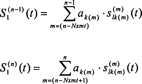
Das erste Bild kann erhalten werden
nach Nxmt Emissionen. Die Gleichung (6)
kann umgeschrieben werden als: ![]()
![]()
Die Gleichung (10) zeigt, dass ein
neues Einzelbild gebildet werden kann nach jeder Emission n ≥ Nxmt durch Summieren der strahlgeformten Geraden
s(m)
li(m), n – Nxmt < m ≤ n. Für zwei aufeinander
folgende Emissionen ist der Ausdruck: 
Aus der Gleichung (9) kann man sehen, dass k(n) = k(n – Nxmt). Bei der rekursiven Bilderzeugung wird ein neues Einzelbild erzeugt bei der Emission n durch Hinzufügen der neuen Information Info(n) zum Bild Image(n-1) und Abziehen der Information, welche bei der Emission n – Nxmt, Info(n-Nmxmt). Die Anzahl der Summationen pro Probe vermindert sich von Nxmt in Gleichung (6) auf lediglich zwei.From equation (9) it can be seen that k (n) = k (n - N xmt ). In the recursive image generation, a new individual image is generated for the emission n by adding the new information Info (n) to the image Image (n-1) and subtracting the information which is associated with the emission n - N xmt , Info (n-Nmxmt) , The number of summations per sample is reduced from N xmt in equation (6) to only two.
Da ein neues Einzelbild, welches aus einer Anzahl von gleichzeitig strahlgeformten Linien besteht, mit jeder Puls-Emission erzeugt wird, wird das Bild alle 200 μs aktualisiert, wenn c = 1540 m/s, und die Daten werden erfasst mit einer Tiefe von 15 cm.Since a new single picture, which consists of a number of simultaneously shaped lines, generated with every pulse emission, the image is updated every 200 μs, if c = 1540 m / s, and the data is collected with a depth of 15 cm.
Nur-addieren-rekursive BilderzeugungJust-add-recursive imaging
Um den Umfang des benötigten Speichers
zu vermindern, kann die Berechnungsprozedur zur Nur-addieren-rekursiven
Bilderzeugung modifiziert werden: Man betrachte die folgenden Gleichungen: 
Die obigen Gleichungen können verwendet
werden, um für
die rekursive Bilderzeugung eine andere Formel abzuleiten:
Der Unterschied zwischen den Gleichungen (12) und (15) besteht darin, dass die Information, welche erhalten wird durch Emittieren mit dem Element k, exponentiell mit der Zeit verschwindet anstatt abgezogen zu werden. Auf diese Weise neigt die Information aus der Vergangenheit weniger dazu, Bewegungs-Artefakte im Bild einzuführen. Der andere Vorteil liegt darin, dass weniger Speicher benötigt wird, da lediglich zwei Einzelbilder gespeichert werden.The difference between the equations (12) and (15) is that the information received becomes by emitting with the element k, exponentially with time disappears instead of being pulled off. That way tends the information from the past is less about moving artifacts in the Introduce picture. The other advantage is that less memory is needed because only two single images are saved.
Die Gleichung (15) kann umgeschrieben
werden als eine Summe von Signalen von zwei aufeinander folgenden
Emissionen: 
Hier ist der Beitrag eines Elements
der Betrag, der Information C (n) / lk addiert zum Signal S (n) / l durch Emissionen
mit dem Element k bis zu dem Zeitpunkt der Emission n. Der Beitrag
des augenblicklich emittierenden Elements (k(n) = i) zu S (n) / l beträgt:
Dies ist eine geometrische Reihe.
Falls das Gewebe bewegungslos ist, gilt:
![]()
![]()
Falls b = 0,8 und Nxmt = 64, dann C (n) / li(t) ≈ s (n) / li(t). Dies bedeutet, dass zur Emission n der Beitrag des emittierenden Elements ungefähr gleich ist der neu erfassten Information.If b = 0.8 and N xmt = 64, then C (n) / li (t) ≈ s (n) / li (t). This means that the contribution of the emitting element to emission n is approximately equal to the newly recorded information.
Mit den gewählten Werten von b und Nxmt ist der Beitrag zum Signal Sl von der vorangegangenen Emission mit demselben Element 128 dB niedriger als der Beitrag des augenblicklichen Elements und Bewegungs-Artefakte können vernachlässigt werden.With the chosen values of b and N xmt , the contribution to the signal S 1 from the previous emission with the same element is 128 dB lower than the contribution of the current element and movement artifacts can be neglected.
Verbesserung des Signal-/Rausch-VerhältnissesImprovement of the signal-to-noise ratio
Der Vorteil des oben dargestellten Bilderzeugungsansatzes liegt darin, dass ein dynamisch fokussiertes Bild beim Senden und Empfangen erhalten wird. Dies wird ermöglicht, weil ein einziges kleines Transducer-Element eine beinahe sphä rische Welle emittiert, welche unzweideutig die Fortpflanzungszeit der Ultraschall-Energie bestimmt.The advantage of the above Imaging approach is that a dynamically focused Image is received when sending and receiving. This enables because a single small transducer element is an almost spherical wave which emits unambiguously the propagation time of the ultrasound energy certainly.
Der Nachteil liegt darin, dass die
Energie, welche in den Körper
gesendet werden kann, mit nur einem Feldelement nicht ausreicht,
um eine hohe Durchdringungstiefe zu erhalten. Eine Möglichkeit,
die Durchdringungstiefe zu erhöhen,
besteht darin, Energie mit mehreren Elementen zu emittieren, wie
vorgeschlagen in [2]. Die Verzögerungen
der Elemente werden so eingestellt, dass sie das Strahlungsmuster
eines einzelnen Elements approximieren. Dabei werden die Verzögerungen
berechnet durch: ![]()
![]()
Der Einfachheit halber ist Nactive gewöhnlich eine ungerade Zahl, um die Gegenwart eines Zentralelements sicher zu stellen. Die Verzögerungen beim Empfangen werden berechnet durch die Formel (8), unter der Annahme, dass das sendende Element die Koordinate xa hat.For convenience, N active is usually an odd number to ensure the presence of a central element. The delays in receiving are calculated by the formula (8), assuming that the sending element has the coordinate x a .
Das Ergebnis der Verwendung mehrfacher
Elemente beim Senden liegt darin, dass das Signal-/Rauschverhältnis erhöht wird.
Sei die Zahl der Übertragungen
Nxmt und die Zahl der Empfängerelemente Nrcv, dann ist das Signal/Rauschverhältnis proportional
zu: ![]()
![]()
Falls die Zahl der Elemente in der
aktiven Sub-Apertur Nactive ist, dann wird
SNR proportional zu: ![]()
![]()
Damit ergibt sich unter Verwendung einer aktiven Apertur beim Senden mit Nactive = 11 ein um 11 dB erhöhtes Signal-/Rauschverhältnis.This results in an 11 dB increased signal / noise ratio when using an active aperture when transmitting with N active = 11.
Unter Verwendung dieses Ansatzes kann ein kontinuierliches Bild, welches aus einer Anzahl von gleichzeitig strahlgeformten Zeilen besteht, hergestellt werden mit der Puls-Wiederhol-Frequenz des emittierten Ultraschalls, womit ermöglicht wird, einer Gewebebewegung zu folgen.Using this approach can be a continuous image consisting of a number of simultaneously beam-shaped lines exist, are produced with the pulse repetition frequency of the emitted ultrasound, which enables tissue movement to follow.
Durch Verwendung eines Feld-Transducers kann ein Sektor-Abtastbild hergestellt werden.By using a field transducer a sector scan image can be produced.
Unter Verwendung eines Matrix-Transducers kann ein volumetrisches Bild hergestellt werden.Using a matrix transducer can create a volumetric image.
Unter Verwendung mehrerer Transducer-Elemente während der Übertragung kann ein verbessertes Signal-/Rauschverhältnis erhalten werden.Using multiple transducer elements while the transfer an improved signal-to-noise ratio can be obtained.
Unter Verwendung einer rekursiven Bilderzeugung können Geschwindigkeitsbilder verbessert werden und Geschwindigkeitsverteilungen können im ganzen Bild aufgefunden werden.Using a recursive Imaging can Speed images are improved and speed distributions can can be found in the whole picture.
Kurze Beschreibung der ZeichnungenShort description of the drawings
Beschreibung der bevorzugten Ausführungsformendescription of the preferred embodiments
In
Ein typisches Beispiel ist eine Visualisierung von den Organen im menschlichen Körper oder die Bestimmung eines Blutflusses.A typical example is a visualization of the organs in the human body or the determination of one Blood flow.
In
Der Pulser
In der bevorzugten Ausführungsform wird derselbe lineare Feld-Transducer verwendet sowohl zum Senden als auch Empfangen des gepulsten Ultraschall-Feldes. Er besteht aus 64 Elementen mit einer Elementbreite von 0,26 mm und einer Beabstandung zwischen benachbarten Elementen von 0,03 mm. Die Höhe der Elemente beträgt 10 mm.In the preferred embodiment the same linear field transducer is used for both sending as well as receiving the pulsed ultrasound field. It exists 64 elements with an element width of 0.26 mm and a spacing between adjacent elements of 0.03 mm. The height of the elements is 10 mm.
Simulationen dokumentieren die Wirkungsweise der Vorrichtung experimentell. Die Simulation wird durchgeführt unter Verwendung des Puls-Antwortverfahrens, das von Tupholme und von Stepanishen [5] entwickelt wurde in der Implementierung, die von Jensen und Svendsen [7] entwickelt wurde. Die hohe Genauigkeit dieser Vorgehensweise, im Vergleich zu Messungen, wird in Jensen [8] beschrieben. Die Veröffentlichung zeigte, dass die Simulationen innerhalb von 1% der gemessenen Ultraschallfelder waren. Der Simulationsansatz kann angewandt werden für gepulste Felder und wird verwendet zum dreidimensionalen Modellieren der Antwort auf mehrfache Streuer.Simulations document the mode of action the device experimentally. The simulation is carried out under Using the pulse response method used by Tupholme and Stepanishen [5] was developed in the implementation by Jensen and Svendsen [7] was developed. The high accuracy of this The procedure in comparison to measurements is described in Jensen [8]. The publication showed that the simulations are within 1% of the measured ultrasonic fields were. The simulation approach can be used for pulsed Fields and is used for three-dimensional modeling of the answer on multiple spreaders.
In der bevorzugten Ausführungsform werden einzelne Elemente nacheinander gepulst und die empfangenen Signale werden auf allen Elementen des Transducers gemessen. Die Ultraschallstrahlen werden dann fokussiert sowohl beim Senden als auch Empfangen in allen Richtungen des Bildes. Nach jeder Emission wird die alte Information von der vorherigen Emission mit dem Element subtrahiert und neue Information wird hinzugefügt. Das Bild wird auf diese Weise kontinuierlich aktualisiert.In the preferred embodiment individual elements are pulsed one after the other and the received ones Signals are measured on all elements of the transducer. The Ultrasound beams are then focused both when sending and also receiving in all directions of the picture. After each emission the old information from the previous emission with the element subtracts and new information is added. The picture is on this Way continuously updated.
Die Simulationsparameter sind in
Tabelle 1 und Tabelle 2 aufgelistet. Eine Abtastfrequenz von f =
105 MHz wird für
die Simulationen verwendet, um eine hohe Genauigkeit in den numerischen
Berechnungen des akustischen Feldes zu erhalten. Beim Erzeugen der
Ergebnisse wird das Signal jedoch 10 Mal vermindert nach der Strahlformung.
Der Anregungspuls, der verwendet wird, ist in
Die Punkt-Spreiz-Funktion (psf) gibt die Qualität des Ultraschallsystems detailliert an. Sie wurde erhalten durch Platzieren eines Punkt-Streuers vor den Transducer und zum Erzeugen eines B-Modus-Bildes (senden – reflektieren – empfangen). Die RF-Zeilen werden Einhüllende-detektiert durch eine Hilbert-Transformation und logarithmisch komprimiert.The point spread function (psf) gives the quality of the ultrasound system in detail. It was obtained through Place a point spreader in front of the transducer and generate it a B-mode image (send - reflect - receive). The RF lines are envelope-detected through a Hilbert transformation and logarithmically compressed.
Die dargestellten Bilder sind um 90° phasenversetzte Feldbilder. Der Abtastungs-Umwandlungsalgorithmus führt eine bi-lineare Interpolation durch, bevor die Bilder angezeigt werden.The images shown are around 90 ° out of phase Field images. The scan conversion algorithm leads one bi-linear interpolation before the images are displayed.
Die Graphen der Punkt-Spreiz-Funktion
werden erzeugt durch Annehmen des Maximalwerts des Einhüllende-detektierten
Signals (siehe
Ein anderer Parameter, der in den
Figuren angegeben ist, ist die "Anzahl
von ausgelassenen Elementen".
Sie gibt an, wie viele Emissionen durchgeführt wurden, bevor dasselbe
Element wiederverwendet wird. Die Beziehung zwischen diesen Parametern
ist in
Die Elemente werden stets beim Senden
in derselben Reihenfolge verwendet. Das bedeutet z. B. in
Um die Durchdringungstiefe und das
Signal-/Rauschverhältnis
zu vermindern, kann mehr als ein Element während des Sendens verwendet
werden. Die Vorstellung ist, eine sphärische Welle zu senden mit
elf Elementen. Ein Hanning-Fenster wird angewandt auf die Amplituden
der sendenden Elemente. Die empfangenen Signale werden nicht gewichtet
(es wird keine Sende-Apodisierung angewandt).
Tabellentables


Claims (25)


Applications Claiming Priority (3)
| Application Number | Priority Date | Filing Date | Title |
|---|---|---|---|
| DKPA199900635 | 1999-05-10 | ||
| WOPCT/DK99/00635 | 1999-05-10 | ||
| PCT/DK2000/000245 WO2000068931A1 (en) | 1999-05-10 | 2000-05-10 | Recursive ultrasound imaging |
Publications (2)
| Publication Number | Publication Date |
|---|---|
| DE60003927D1 DE60003927D1 (en) | 2003-08-21 |
| DE60003927T2 true DE60003927T2 (en) | 2004-05-06 |
Family
ID=8095822
Family Applications (1)
| Application Number | Title | Priority Date | Filing Date |
|---|---|---|---|
| DE60003927T Expired - Lifetime DE60003927T2 (en) | 1999-05-10 | 2000-05-10 | RECURSIVE ULTRASONIC ILLUSTRATION |
Country Status (6)
| Country | Link |
|---|---|
| US (1) | US6689063B1 (en) |
| EP (1) | EP1194920B1 (en) |
| AT (1) | ATE245301T1 (en) |
| AU (1) | AU4393400A (en) |
| DE (1) | DE60003927T2 (en) |
| WO (1) | WO2000068931A1 (en) |
Families Citing this family (35)
| Publication number | Priority date | Publication date | Assignee | Title |
|---|---|---|---|---|
| DE60139403D1 (en) * | 2001-10-02 | 2009-09-10 | B K Medical As | Method and apparatus for speed estimation in synthetic aperture imaging |
| JP4269623B2 (en) * | 2002-10-07 | 2009-05-27 | 株式会社 東北テクノアーチ | Blood flow visualization diagnostic device |
| DE10334902B3 (en) * | 2003-07-29 | 2004-12-09 | Nutronik Gmbh | Signal processing for non-destructive object testing involves storing digitized reflected ultrasonic signals and phase-locked addition of stored amplitude values with equal transition times |
| US7963919B2 (en) | 2005-12-07 | 2011-06-21 | Siemens Medical Solutions Usa, Inc. | Ultrasound imaging transducer array for synthetic aperture |
| US8465431B2 (en) | 2005-12-07 | 2013-06-18 | Siemens Medical Solutions Usa, Inc. | Multi-dimensional CMUT array with integrated beamformation |
| JP4984519B2 (en) * | 2005-12-19 | 2012-07-25 | Jfeスチール株式会社 | Method and apparatus for inspecting cross section of metal material by ultrasonic wave |
| WO2007120890A2 (en) * | 2006-04-13 | 2007-10-25 | The Research Foundation Of State University Of New York | Phased array ultrasound with electronically controlled focal point for assessing bone quality via acoustic topology and wave transmit functions |
| US9084574B2 (en) * | 2006-11-10 | 2015-07-21 | Siemens Medical Solution Usa, Inc. | Transducer array imaging system |
| US7984651B2 (en) * | 2006-11-10 | 2011-07-26 | Penrith Corporation | Transducer array imaging system |
| US20080114241A1 (en) * | 2006-11-10 | 2008-05-15 | Penrith Corporation | Transducer array imaging system |
| US20070161904A1 (en) * | 2006-11-10 | 2007-07-12 | Penrith Corporation | Transducer array imaging system |
| US20080114251A1 (en) * | 2006-11-10 | 2008-05-15 | Penrith Corporation | Transducer array imaging system |
| US20080112265A1 (en) * | 2006-11-10 | 2008-05-15 | Penrith Corporation | Transducer array imaging system |
| US8490489B2 (en) * | 2006-11-10 | 2013-07-23 | Siemens Medical Solutions Usa, Inc. | Transducer array imaging system |
| US20080114247A1 (en) * | 2006-11-10 | 2008-05-15 | Penrith Corporation | Transducer array imaging system |
| US8220334B2 (en) | 2006-11-10 | 2012-07-17 | Penrith Corporation | Transducer array imaging system |
| US8600299B2 (en) * | 2006-11-10 | 2013-12-03 | Siemens Medical Solutions Usa, Inc. | Transducer array imaging system |
| US8312771B2 (en) * | 2006-11-10 | 2012-11-20 | Siemens Medical Solutions Usa, Inc. | Transducer array imaging system |
| US8079263B2 (en) * | 2006-11-10 | 2011-12-20 | Penrith Corporation | Transducer array imaging system |
| US8499634B2 (en) | 2006-11-10 | 2013-08-06 | Siemens Medical Solutions Usa, Inc. | Transducer array imaging system |
| US9295444B2 (en) * | 2006-11-10 | 2016-03-29 | Siemens Medical Solutions Usa, Inc. | Transducer array imaging system |
| US7891230B2 (en) * | 2007-02-08 | 2011-02-22 | Penrith Corporation | Methods for verifying the integrity of probes for ultrasound imaging systems |
| US20080194960A1 (en) * | 2007-02-08 | 2008-08-14 | Randall Kevin S | Probes for ultrasound imaging systems |
| US20080194963A1 (en) * | 2007-02-08 | 2008-08-14 | Randall Kevin S | Probes for ultrasound imaging systems |
| US9706976B2 (en) * | 2007-02-08 | 2017-07-18 | Siemens Medical Solutions Usa, Inc. | Ultrasound imaging systems and methods of performing ultrasound procedures |
| US20080194961A1 (en) * | 2007-02-08 | 2008-08-14 | Randall Kevin S | Probes for ultrasound imaging systems |
| US7940972B2 (en) * | 2007-05-16 | 2011-05-10 | General Electric Company | System and method of extended field of view image acquisition of an imaged subject |
| US9117439B2 (en) | 2008-03-13 | 2015-08-25 | Supersonic Imagine | Method and apparatus for ultrasound synthetic imagining |
| CA2789129C (en) | 2010-02-08 | 2017-08-22 | Dalhousie University | Ultrasound imaging system using beamforming techniques for phase coherence grating lobe suppression |
| US9638798B2 (en) * | 2010-09-20 | 2017-05-02 | B-K Medical Aps | Imaging transducer array |
| KR101893383B1 (en) * | 2012-03-02 | 2018-08-31 | 삼성전자주식회사 | Apparatus and method for generating ultrasonic image |
| US9855022B2 (en) | 2015-01-19 | 2018-01-02 | B-K Medical Aps | 3-D flow estimation using row-column addressed transducer arrays |
| US10697939B2 (en) * | 2018-03-02 | 2020-06-30 | B-K Medical Aps | Synthetic fine-pitch ultrasound imaging |
| CN109350112B (en) * | 2018-11-13 | 2020-06-12 | 飞依诺科技(苏州)有限公司 | Ultrasonic image imaging method and device and medical equipment |
| CN117320635A (en) | 2021-04-02 | 2023-12-29 | 国家医疗保健研究所 | Diverging lens array |
Family Cites Families (6)
| Publication number | Priority date | Publication date | Assignee | Title |
|---|---|---|---|---|
| US5121361A (en) * | 1989-09-29 | 1992-06-09 | Acoustic Imaging Technologies Corporation | Programmable beam former |
| EP0480086A1 (en) * | 1990-10-05 | 1992-04-15 | Acoustic Imaging Technologies Corporation | Programmable beam former |
| US5345939A (en) | 1993-11-24 | 1994-09-13 | General Electric Company | Ultrasound imaging system with dynamic window function |
| US5483963A (en) * | 1994-07-22 | 1996-01-16 | Loral Infrared & Imaging Systems, Inc. | Two dimensional transducer integrated circuit |
| US5511550A (en) * | 1994-10-14 | 1996-04-30 | Parallel Design, Inc. | Ultrasonic transducer array with apodized elevation focus |
| US5732706A (en) * | 1996-03-22 | 1998-03-31 | Lockheed Martin Ir Imaging Systems, Inc. | Ultrasonic array with attenuating electrical interconnects |
-
2000
- 2000-05-10 AT AT00925096T patent/ATE245301T1/en not_active IP Right Cessation
- 2000-05-10 AU AU43934/00A patent/AU4393400A/en not_active Abandoned
- 2000-05-10 WO PCT/DK2000/000245 patent/WO2000068931A1/en active IP Right Grant
- 2000-05-10 US US09/959,847 patent/US6689063B1/en not_active Expired - Lifetime
- 2000-05-10 EP EP00925096A patent/EP1194920B1/en not_active Expired - Lifetime
- 2000-05-10 DE DE60003927T patent/DE60003927T2/en not_active Expired - Lifetime
Also Published As
| Publication number | Publication date |
|---|---|
| EP1194920A1 (en) | 2002-04-10 |
| DE60003927D1 (en) | 2003-08-21 |
| US6689063B1 (en) | 2004-02-10 |
| EP1194920B1 (en) | 2003-07-16 |
| AU4393400A (en) | 2000-11-21 |
| WO2000068931A1 (en) | 2000-11-16 |
| ATE245301T1 (en) | 2003-08-15 |
Similar Documents
| Publication | Publication Date | Title |
|---|---|---|
| DE60003927T2 (en) | RECURSIVE ULTRASONIC ILLUSTRATION | |
| DE10224234B4 (en) | System and method for phase reversal ultrasound imaging | |
| DE19756730B4 (en) | A method, apparatus and applications for combining transmit wave functions to obtain a synthetic waveform in an ultrasound imaging system | |
| DE60028952T2 (en) | METHOD AND DEVICE FOR GENERATING PICTURES THROUGH THE USE OF SHEARS | |
| DE102005034697B4 (en) | Contrast agent imaging with (contrast) means-specific ultrasound detection | |
| DE69533059T2 (en) | ULTRASONIC SPECTRAL CONTRASTING | |
| EP0256481B1 (en) | Method and equipment for adaptive focussing in a medical ultrasonic imaging apparatus | |
| DE69937422T2 (en) | Ultrasound imaging by means of coded excitation during transmission and selective filtering during reception | |
| DE69923748T2 (en) | Method and device for ultrasonic image data acquisition with increase of the image frequency and image resolution | |
| DE10262408B3 (en) | Block switching with ultrasound imaging | |
| DE19843219B4 (en) | Method and apparatus for ultrasonic beamforming with spatially coded transmissions | |
| DE19912089B4 (en) | Method and apparatus for color-flux imaging using Golay-coded excitation during transmission and pulse compression on reception | |
| Nikolov et al. | Recursive ultrasound imaging | |
| DE10050232A1 (en) | High-resolution ultrasound tomograph | |
| DE19913198A1 (en) | Method and device for improved flow imaging in B-mode ultrasound | |
| DE10050366A1 (en) | System for imaging ultrasonic dispersers has display level system for displaying image with first and second scan lines that are functions of first and second path-summed received signals | |
| DE10217342A1 (en) | Medical ultrasound imaging using an echo beam bundling instrument with high spatial bandwidth so that a reduced number of transmit-receive events is required to generate a complete image | |
| DE102017211895A1 (en) | Tissue characterization in medical diagnostic ultrasound | |
| DE2645738A1 (en) | ULTRASONIC BEAM SCANNING | |
| DE3104014A1 (en) | "ULTRASONIC SCANNER" | |
| DE10215742A1 (en) | Ultrasound transmission / reception method, ultrasound transmission / reception device, ultrasound imaging method and ultrasound imaging device | |
| DE112018003501T5 (en) | ULTRASOUND IMAGING WITH SPECTRAL COMPOUNDING FOR SPECKLE REDUCTION | |
| DE4209394A1 (en) | Ultrasonic device with probe for ultrasonic diagnostics of blood vessels - is arranged in catheter to enable three=dimensional imaging or tomography using frequencies of 10 MHZ or more | |
| DE10252077A1 (en) | Beam composition method and apparatus | |
| DE60308985T2 (en) | Ultrasound imaging device and method |
Legal Events
| Date | Code | Title | Description |
|---|---|---|---|
| 8364 | No opposition during term of opposition |