DE60003581T2 - UNINTERRUPTIBLE POWER SUPPLY (UPS) WITH A CONTROL DEVICE FOR CHARGING A BATTERY AND METHOD FOR CHARGING - Google Patents

UNINTERRUPTIBLE POWER SUPPLY (UPS) WITH A CONTROL DEVICE FOR CHARGING A BATTERY AND METHOD FOR CHARGING Download PDF

Info

Publication number
DE60003581T2
DE60003581T2 DE60003581T DE60003581T DE60003581T2 DE 60003581 T2 DE60003581 T2 DE 60003581T2 DE 60003581 T DE60003581 T DE 60003581T DE 60003581 T DE60003581 T DE 60003581T DE 60003581 T2 DE60003581 T2 DE 60003581T2
Authority
DE
Germany
Prior art keywords
value
accumulator
open circuit
block
circuit voltage
Prior art date
Legal status (The legal status is an assumption and is not a legal conclusion. Google has not performed a legal analysis and makes no representation as to the accuracy of the status listed.)
Expired - Lifetime
Application number
DE60003581T
Other languages
German (de)
Other versions
DE60003581D1 (en
Inventor
Teuvo Suntio
Current Assignee (The listed assignees may be inaccurate. Google has not performed a legal analysis and makes no representation or warranty as to the accuracy of the list.)
Delta Energy Systems Switzerland AG
Original Assignee
Ascom Energy Systems AG
Priority date (The priority date is an assumption and is not a legal conclusion. Google has not performed a legal analysis and makes no representation as to the accuracy of the date listed.)
Filing date
Publication date
Application filed by Ascom Energy Systems AG filed Critical Ascom Energy Systems AG
Application granted granted Critical
Publication of DE60003581D1 publication Critical patent/DE60003581D1/en
Publication of DE60003581T2 publication Critical patent/DE60003581T2/en
Anticipated expiration legal-status Critical
Expired - Lifetime legal-status Critical Current

Links

Classifications

    • HELECTRICITY
    • H02GENERATION; CONVERSION OR DISTRIBUTION OF ELECTRIC POWER
    • H02JCIRCUIT ARRANGEMENTS OR SYSTEMS FOR SUPPLYING OR DISTRIBUTING ELECTRIC POWER; SYSTEMS FOR STORING ELECTRIC ENERGY
    • H02J7/00Circuit arrangements for charging or depolarising batteries or for supplying loads from batteries
    • H02J7/0013Circuit arrangements for charging or depolarising batteries or for supplying loads from batteries acting upon several batteries simultaneously or sequentially
    • H02J7/0014Circuits for equalisation of charge between batteries
    • HELECTRICITY
    • H02GENERATION; CONVERSION OR DISTRIBUTION OF ELECTRIC POWER
    • H02JCIRCUIT ARRANGEMENTS OR SYSTEMS FOR SUPPLYING OR DISTRIBUTING ELECTRIC POWER; SYSTEMS FOR STORING ELECTRIC ENERGY
    • H02J7/00Circuit arrangements for charging or depolarising batteries or for supplying loads from batteries
    • H02J7/007Regulation of charging or discharging current or voltage
    • H02J7/00712Regulation of charging or discharging current or voltage the cycle being controlled or terminated in response to electric parameters
    • H02J7/00714Regulation of charging or discharging current or voltage the cycle being controlled or terminated in response to electric parameters in response to battery charging or discharging current
    • H02J7/00718Regulation of charging or discharging current or voltage the cycle being controlled or terminated in response to electric parameters in response to battery charging or discharging current in response to charge current gradient
    • HELECTRICITY
    • H02GENERATION; CONVERSION OR DISTRIBUTION OF ELECTRIC POWER
    • H02JCIRCUIT ARRANGEMENTS OR SYSTEMS FOR SUPPLYING OR DISTRIBUTING ELECTRIC POWER; SYSTEMS FOR STORING ELECTRIC ENERGY
    • H02J7/00Circuit arrangements for charging or depolarising batteries or for supplying loads from batteries
    • H02J7/007Regulation of charging or discharging current or voltage
    • H02J7/00712Regulation of charging or discharging current or voltage the cycle being controlled or terminated in response to electric parameters
    • H02J7/007182Regulation of charging or discharging current or voltage the cycle being controlled or terminated in response to electric parameters in response to battery voltage
    • H02J7/007184Regulation of charging or discharging current or voltage the cycle being controlled or terminated in response to electric parameters in response to battery voltage in response to battery voltage gradient
    • HELECTRICITY
    • H02GENERATION; CONVERSION OR DISTRIBUTION OF ELECTRIC POWER
    • H02JCIRCUIT ARRANGEMENTS OR SYSTEMS FOR SUPPLYING OR DISTRIBUTING ELECTRIC POWER; SYSTEMS FOR STORING ELECTRIC ENERGY
    • H02J9/00Circuit arrangements for emergency or stand-by power supply, e.g. for emergency lighting
    • H02J9/04Circuit arrangements for emergency or stand-by power supply, e.g. for emergency lighting in which the distribution system is disconnected from the normal source and connected to a standby source
    • H02J9/06Circuit arrangements for emergency or stand-by power supply, e.g. for emergency lighting in which the distribution system is disconnected from the normal source and connected to a standby source with automatic change-over, e.g. UPS systems
    • YGENERAL TAGGING OF NEW TECHNOLOGICAL DEVELOPMENTS; GENERAL TAGGING OF CROSS-SECTIONAL TECHNOLOGIES SPANNING OVER SEVERAL SECTIONS OF THE IPC; TECHNICAL SUBJECTS COVERED BY FORMER USPC CROSS-REFERENCE ART COLLECTIONS [XRACs] AND DIGESTS
    • Y02TECHNOLOGIES OR APPLICATIONS FOR MITIGATION OR ADAPTATION AGAINST CLIMATE CHANGE
    • Y02BCLIMATE CHANGE MITIGATION TECHNOLOGIES RELATED TO BUILDINGS, e.g. HOUSING, HOUSE APPLIANCES OR RELATED END-USER APPLICATIONS
    • Y02B70/00Technologies for an efficient end-user side electric power management and consumption
    • Y02B70/30Systems integrating technologies related to power network operation and communication or information technologies for improving the carbon footprint of the management of residential or tertiary loads, i.e. smart grids as climate change mitigation technology in the buildings sector, including also the last stages of power distribution and the control, monitoring or operating management systems at local level
    • YGENERAL TAGGING OF NEW TECHNOLOGICAL DEVELOPMENTS; GENERAL TAGGING OF CROSS-SECTIONAL TECHNOLOGIES SPANNING OVER SEVERAL SECTIONS OF THE IPC; TECHNICAL SUBJECTS COVERED BY FORMER USPC CROSS-REFERENCE ART COLLECTIONS [XRACs] AND DIGESTS
    • Y04INFORMATION OR COMMUNICATION TECHNOLOGIES HAVING AN IMPACT ON OTHER TECHNOLOGY AREAS
    • Y04SSYSTEMS INTEGRATING TECHNOLOGIES RELATED TO POWER NETWORK OPERATION, COMMUNICATION OR INFORMATION TECHNOLOGIES FOR IMPROVING THE ELECTRICAL POWER GENERATION, TRANSMISSION, DISTRIBUTION, MANAGEMENT OR USAGE, i.e. SMART GRIDS
    • Y04S20/00Management or operation of end-user stationary applications or the last stages of power distribution; Controlling, monitoring or operating thereof
    • Y04S20/20End-user application control systems

Landscapes

  • Engineering & Computer Science (AREA)
  • Power Engineering (AREA)
  • Secondary Cells (AREA)
  • Charge And Discharge Circuits For Batteries Or The Like (AREA)

Description

Die vorliegende Erfindung betrifft im allgemeinen Akkumulator-betriebene unterbrechungsfreie Stromversorgungssysteme. Insbesondere betrifft die vorliegende Erfindung die optimale Kontrolle der Ladung und Entladung der in einem derartigen System verwendeten Akkumulatoren.The present invention relates to generally battery powered uninterruptible power systems. In particular, the present invention relates to optimal control the charge and discharge of those used in such a system Accumulators.

In vielen elektrischen Anlagen, wird ein unterbrechungsfreies Stromversorgungs-(UPS)-System zur Sicherstellung des Betriebs der elektrischen Anlagen unabhängig von Störungen in dem Energieversorgungsnetz verwendet. Das "unterbrechungsfreie Stromversorgungssystem" kann auch abgekürzt und als die "elektrische Hilfsversorgung" bezeichnet werden.In many electrical systems, will an uninterruptible power supply (UPS) system for backup the operation of the electrical systems regardless of faults in the energy supply network used. The "uninterrupted Power supply system " also abbreviated and as the "electrical Aid provision " become.

1 stellt eine allgemeine einfache elektrische Hilfsversorgung dar. Die mit dem Energieversorgungsnetz verbundene Wechselstromversorgungsleitung 101 ist mit den Gleichrichtereinheiten verbunden, deren Anzahl nur Eins sein kann, wobei jedoch üblicherweise einige Einheiten parallelgeschaltet sind. 1 präsentiert insbesondere die Gleichrichtereinheiten 102 und 103. Sie erzeugen eine bestimmte Gleichspannung, welche über die Speiseleitung 104 der Last, d. h., der Vorrichtung 105 zugeführt wird, deren Energieversorgung sichergestellt werden soll. Die Speiseleitung 104 ist auch über den Schalter 106 mit der Akkumulatoreinheit 107 verbunden. Das System funktioniert so, dass während des Normalbetriebs des Energieverteilungsnetzes die Gleichrichtereinheiten 102 und 103 elektrische Energie sowohl an die Last 105 als auch an die Akkumulatoreinheit 107 liefern, wobei in diesem Falle die Akkumulatoreinheit im geladenen Zustand bleibt. Wenn eine Störung in dem Energieversorgungsnetz auftritt, beginnt sich der Akkumulator zu der Last 105 hin zu entladen, deren elektrische Energieversorgung somit nicht gestört wird. wenn das Energieverteilungsnetz zu seinem normalen Betrieb zurückkehrt beginnen die Gleichrichtereinheiten 102 und 103 wieder mit der Lieferung von elektrischer Energie sowohl an die Last als auch an die Akkumulatoreinheit. Dann wird die Akkumulatoreinheit mit derselben Menge an elektrischer Ladung nachgeladen, welche während der Störung entladen wurde. Der Schalter 106 wird nur unter speziellen Bedingungen geöffnet, z. B., wenn die Störung lange dauert, und die Akkumulatoreinheit beinahe vollständig entladen ist und die, Lieferung von Energie nicht ohne das Risiko einer Beschädigung der Akkumulatoreinheit fortgesetzt werden kann. 1 represents a general simple electrical auxiliary supply. The AC supply line connected to the power supply network 101 is connected to the rectifier units, the number of which can only be one, but usually a few units are connected in parallel. 1 especially presents the rectifier units 102 and 103 , They generate a certain DC voltage, which via the feed line 104 the load, ie the device 105 is supplied, whose energy supply is to be ensured. The feed line 104 is also over the switch 106 with the accumulator unit 107 connected. The system works in such a way that the rectifier units operate during normal operation of the power distribution network 102 and 103 electrical energy to both the load 105 as well as the accumulator unit 107 deliver, in which case the accumulator unit remains in the charged state. If a fault occurs in the power supply network, the accumulator begins to load 105 to discharge, whose electrical energy supply is not disrupted. when the power distribution network returns to normal operation, the rectifier units begin 102 and 103 again with the supply of electrical energy to both the load and the accumulator unit. The accumulator unit is then recharged with the same amount of electrical charge that was discharged during the fault. The desk 106 is only opened under special conditions, e.g. B. if the fault lasts for a long time and the accumulator unit is almost completely discharged and the delivery of energy cannot continue without the risk of damage to the accumulator unit.

Wenn die Akkumulatoreinheit kontinuierlich mit der Ladespannung verbunden ist, wird dieses als permanente Ladung bezeichnet. Der Spannungspegel der permanenten Ladung muss genau gemäß den Empfehlungen des Akkumulatorherstellers gewählt werden, um eine möglichst lange Betriebslebensdauer der Akkumulatoreinheit sicherzustellen. Es hat sich jedoch herausgestellt, dass geschlossene sogenannte VRLA-Akkumulatoren (Valve Regulated Lead-Acid), welche derzeit im allgemeinen in Akkumulatoreinheiten verwendet werden, schlecht eine permanente Ladung im Vergleich zu den herkömmlichen offenen, d. h., den gefluteten Bleiakkumulatoren tolerieren. Dieses, so glaubt man, wird durch chemische Phänomene innerhalb der Akkumulatoren bewirkt, welche durch eine kontinuierliche Überladung verursacht werden.If the accumulator unit continuously is connected to the charging voltage, this is called permanent charging designated. The voltage level of the permanent charge must be accurate according to the recommendations of the battery manufacturer selected to be one if possible ensure a long service life of the battery unit. However, it has been found that closed so-called VRLA batteries (Valve Regulated Lead Acid), which are currently in the generally used in accumulator units, bad one permanent charge compared to the conventional open, i.e. i.e. the tolerate flooded lead accumulators. This, it is believed, is caused by chemical phenomena inside the accumulators caused by a continuous overcharge caused.

2 präsentiert eine fortschrittlichere so genannte Reservekonstruktion, welche ansonsten der in 1 dargestellten Konstruktion ähnlich ist, wobei aber eine Verbindungs- und Ladevorrichtung, d. h., ein sogenanntes IBCM-Modul (Intelligent Batterie Connection/Charge Modul) 201 den Trennschalter des Akkumulators ersetzt. Es besitzt eine Steuerverbindung zu der Akkumulatoreinheit 107 (dargestellt durch eine dünne Linie in der Figur) und sie kann die Ladeenergie der Akkumulatoren entweder direkt durch Überbrücken der Gleichrichter von einer Verbindung, mittels welcher das Reservesystem mit dem Energieverteilungsnetz (dargestellt durch eine gestrichelte Linie in der Figur) verbunden ist, oder aus der von den Gleichrichtern erzeugten an die Last gelieferten Spannung übernehmen. Während des Normalbetriebs hält das IBCM-Modul 201 den Akkumulator nahezu vollständig von der von den Gleichrichtereinheiten 102 und 103 gelieferten Gleichspannung, d. h., von der Speiseleitung 104 getrennt. Wenn die Spannung der Speiseleitung 104 unter den Schwellenwert, z. B. wegen der in dem Energieverteilungsnetz auftretenden Störung fällt, verbindet das IBCM-Modul 201 die Akkumulatoreinheit 107 mit der Speiseleitung 104, wobei in diesem Falle die Last, 105 weiter elektrische Energie erhält. 2 presents a more advanced so-called reserve construction, which otherwise the in 1 shown construction is similar, but with a connection and charging device, ie, a so-called IBCM module (Intelligent Battery Connection / Charge Module) 201 the disconnector of the accumulator replaced. It has a control connection to the accumulator unit 107 (represented by a thin line in the figure) and it can charge the rechargeable batteries either directly by bridging the rectifier from a connection by means of which the reserve system is connected to the power distribution network (represented by a dashed line in the figure), or from the Take over the voltage generated by the rectifiers and delivered to the load. The IBCM module stops during normal operation 201 the accumulator almost completely from that of the rectifier units 102 and 103 supplied DC voltage, ie from the feed line 104 Cut. If the voltage of the feed line 104 below the threshold, e.g. B. falls due to the disturbance occurring in the power distribution network, connects the IBCM module 201 the accumulator unit 107 with the feed line 104 , in which case the load, 105 continues to receive electrical energy.

Die Ladung des Akkumulators wird langsam durch ihn selbst auch dann entladen; wenn der Akkumulator nirgendwo angeschlossen ist. Wenn das IBCM-Modul 201 detektiert, dass die Ladung des Akkumulators 107 im normalen Betrieb unter einen, bestimmten Schwellenwert gefallen ist, verbindet sie die Akkumulatoreinheit 107 entweder mit der Speiseleitung. oder durch einen (in 2 nicht dargestellten) getrennten Gleichrichter mit dem Energieversorgungsnetz, wobei in diesem Falle die Akkumulatoreinheit relativ schnell vollständig geladen wird. Danach trennt das IBCM-Modul 201 die Akkumulatoreinheit wieder von der Ladespannung. Es wurde bisher angenommen, dass die Verwendung des IBCM-Moduls die Betriebslebensdauer der Akkumulatoreinheit sogar verdoppeln kann.The battery is then slowly discharged even then; if the accumulator is not connected anywhere. If the IBCM module 201 detects that the charge of the accumulator 107 has fallen below a certain threshold during normal operation, it connects the accumulator unit 107 either with the feed line. or by a (in 2 separate rectifier (not shown) with the power supply network, in which case the accumulator unit is fully charged relatively quickly. The IBCM module then disconnects 201 the accumulator unit again from the charging voltage. It has previously been assumed that the use of the IBCM module can even double the operating life of the accumulator unit.

Das Problem in dem System gemäß 2 ist das Finden des richtigen Kontrollalgorithmus für das IBCM-Modul. Ein falscher Algorithmus kann sogar zu einem schlechteren Betrieb des Systems führen, und dass dieses die Akkumulatoren stärker als das einfache System gemäß 1 verschleißt. Zusätzlich kann ein falscher Algorithmus dazu beitragen, die Produktionskosten zu erhöhen, d. h., wenn die Komponenten der Vorrichtung deshalb für unnötig hohen Strom dimensioniert werden müssen.According to the problem in the system 2 is finding the right control algorithm for the IBCM module. An incorrect algorithm can even lead to poorer system operation and that the accumulators operate more strongly than the simple system 1 wears. In addition, an incorrect algorithm can help to increase production costs, ie if the components of the device therefore have to be dimensioned for unnecessarily high current.

Eine Aufgabe der vorliegenden Erfindung besteht in der Präsentation einer elektrischen Hilfsversorgung, welche eine lange Betriebslebensdauer einer Akkumulatoreinheit ermöglicht und welche wirtschaftlich zu fertigen ist und welche eine gute Anwendbarkeit besitzt. Zusätzlich besteht eine Aufgabe der vorliegenden Erfindung darin, dass die elektrische Hilfsversorgung sich den Veränderungen in den Eigenschaften aufgrund der Produktionstoleranzen und den Veränderungen in der Umgebung anpasst. Eine weitere Aufgabe der Erfindung besteht in der Präsentation eines Verfahrens zum Kontrollieren einer Hilfsversorgung so, dass die vorstehend erwähnten Aufgaben gelöst werden.An object of the present invention consists in the presentation an electrical auxiliary supply, which has a long service life allows an accumulator unit and which one is economical to manufacture and which one has good applicability has. additionally It is an object of the present invention that auxiliary electrical supply to the changes in properties based on production tolerances and changes in the environment. Another object of the invention is to present of a method of controlling an auxiliary care so that those mentioned above Tasks solved become.

Die Aufgaben der Erfindung werden durch die Präsentation und Sicherstellung von Kriterien für den Start und die Beendigung der Ladung des Akkumulators erreicht, dessen primäres Kriterium des Ladestarts auf der in den Blöcken überwachten Veränderung der Zellenleerlaufspannung beruht und das primäre Kriterium des Ladeendes auf dem Wert der zeitlichen Ableitung des Ladestroms und auf dem Wert der zeitlichen Ableitung der Spannungsdifferenz basiert.The objects of the invention will be through the presentation and ensuring criteria for starting and ending the charge of the accumulator reached, its primary criterion of the charging start on the monitored in the blocks change is based on the open circuit voltage and the primary criterion of the end of charging on the value of the time derivative of the charging current and on the Value of the time derivative of the voltage difference based.

Die erfindungsgemäße elektrische Hilfsversorgung weist auf:

  • – einen aus Blöcken bestehenden Akkumulator,
  • – eine Schalteinrichtung zum bedingten Verbinden des Akkumulators mit der Last oder mit der Ladestromversorgung,
  • – Mess- und Kontrolleinrichtungen zum Erzeugen von Messergebnissen zum Beschreiben des Zustandes des Akkumulators und zum Kontrollieren der Schalteinrichtung auf der Basis der erzeugten Messergebnisse.
The electrical auxiliary supply according to the invention has:
  • An accumulator consisting of blocks,
  • A switching device for conditionally connecting the accumulator to the load or to the charging current supply,
  • - Measuring and control devices for generating measurement results for describing the state of the battery and for checking the switching device on the basis of the measurement results generated.

Gemäß der ersten Ausführungsform der Erfindung ist sie gekennzeichnet, dass die Mess- und Kontrolleinrichtungen dafür angeordnet sind:

  • – den blockspezifischen Initialwert der Zellenleerlaufspannung von einem geladenen Akkumulator zu messen,
  • – aus dem gemessenen Initialwert der Zellenleerlaufspannung einen bestimmten Schwellwert zu erzeugen,
  • – den gemessenen Wert der Zellenleerlaufspannung des Blocks mit dem Schwellwert zu vergleichen, und
  • – in einer Reaktion auf die Beobachtung, gemäß welcher die gemessene Zellenleerlaufspannung eines Blocks den Schwellwert erreicht hat, die Schalteinrichtung so zu kontrollieren, dass sie den Akkumulator mit einer bestimmten Ladestromversorgung verbindet.
According to the first embodiment of the invention, it is characterized in that the measuring and control devices are arranged for it:
  • Measure the block-specific initial value of the open circuit voltage of a charged accumulator,
  • To generate a certain threshold value from the measured initial value of the cell open circuit voltage,
  • - compare the measured value of the cell open circuit voltage of the block with the threshold value, and
  • - In response to the observation according to which the measured open circuit voltage of a block has reached the threshold value, to control the switching device in such a way that it connects the accumulator to a specific charging current supply.

Gemäß einer zweiten Ausführungsform der Erfindung ist die Erfindung dadurch gekennzeichnet, dass die Mess- und Kontrolleinrichtungen angeordnet sind, um:

  • – den Wert der Veränderung des Ladestroms im Verhältnis zur Zeit zu messen,
  • – den Wert der Veränderung der Spannungsdifferenz zwischen den Blöcken im Verhältnis zur Zeit zu messen,
  • – als eine Reaktion auf die Beobachtung, gemäß welcher der Wert der Veränderung des Ladestroms im Verhältnis zur Zeit von seinem negativen Grenzwert im wesentlichen zu Null zurückgekehrt ist und der Wert der Veränderung der Spannungsdifferenz zwischen den Blöcken im Verhältnis zur Zeit von dem positiven Grenzwert im wesentlichen zu Null zurückgekehrt ist, die Schalteinrichtung so zu kontrollieren, dass sie Akkumulator von der Ladestromversorgung trennt.
According to a second embodiment of the invention, the invention is characterized in that the measuring and control devices are arranged to:
  • - measure the value of the change in charging current in relation to time,
  • Measure the value of the change in voltage difference between the blocks in relation to time,
  • - in response to the observation that the value of the change in charge current relative to time has substantially returned from its negative limit and the value of change in voltage difference between the blocks relative to time has substantially returned from the positive limit has returned to zero, the switching device should be checked so that it separates the accumulator from the charging current supply.

Die Erfindung betrifft auch ein Verfahren, das gemäß der ersten Ausführungsform dadurch gekennzeichnet ist, dass es aus Phasen besteht, in welchen:

  • – der blockspezifische Initialwert der Zellenleerlaufspannung des geladenen Akkumulators gemessen wird,
  • ein bestimmter Schwellwert aus dem gemessenen blockspezifischen Initialwert der Zellenleerlaufspannung erzeugt wird
  • – der gemessene blockspezifische Wert der Zellenleerlaufspannung mit dem Schwellenwert verglichen wird,
  • – in einer Reaktion auf die Beobachtung, gemäß welcher der gemessene blockspezifische Wert der Zellenleerlaufspannung den Schwellenwert erreicht hat, der Ladestrom mit dem Akkumulator verbunden wird.
The invention also relates to a method which, according to the first embodiment, is characterized in that it consists of phases in which:
  • The block-specific initial value of the open circuit voltage of the charged accumulator is measured,
  • a certain threshold value is generated from the measured block-specific initial value of the cell open circuit voltage
  • The measured block-specific value of the cell open circuit voltage is compared with the threshold value,
  • - In response to the observation according to which the measured block-specific value of the cell open circuit voltage has reached the threshold value, the charging current is connected to the accumulator.

Gemäß der zweiten Ausführungsform der Erfindung ist die Erfindung dadurch gekennzeichnet ist, dass sie aus Phasen besteht, in welchen:

  • – der Wert des Ladestroms im Verhältnis zur Zeit zu gemessen wird,
  • – der Wert der Veränderung der Spannungsdifferenz zwischen den Blöcken im Verhältnis zur Zeit gemessen wird,
  • – als eine Reaktion auf die Beobachtung, gemäß welcher der Wert der Veränderung des Ladestroms im Verhältnis zur Zeit von seinem positiven Grenzwert im wesentlichen zu Null zurückgekehrt ist, der Akkumulator von der Ladestromversorgung getrennt wird.
According to the second embodiment of the invention, the invention is characterized in that it consists of phases in which:
  • - the value of the charging current is measured in relation to time,
  • The value of the change in the voltage difference between the blocks is measured in relation to time,
  • - As a reaction to the observation that the value of the change in the charging current in relation to time has essentially returned to zero from its positive limit value, the accumulator is disconnected from the charging current supply.

Ein VRLA-Akkumulator, welcher auch als eine Kette bezeichnet wird, weist bekanntermaßen Gruppen von Zellen, d. h., Monoblöcke auf, welche weiter aus Zellen bestehen. Es können mehrere VRLA-Akkumulatoren vorhanden sein, so dass sie üblicherweise parallelgeschaltet sind, wobei sie in diesem Falle als eine Akkumulatoreinheit bezeichnet werden. In dem System gemäß der vorliegenden Erfindung wird die Zellenleerlaufspannung am sinnvollsten in jedem Block getrennt überwacht. Zusätzlich werden der Ladestrom und die Temperatur des Akkumulators überwacht. Ein Minimalwert wurde für die Zellenleerlaufspannung des Monoblocks definiert, welche der Zellenleerlaufspannung in dem Falle entspricht, dass die Kapazität des Monoblocks abgesunken ist, wenn der Akkumulator sich auf einen bestimmten minimalen Wert entladen hat. Der Minimalwert berücksichtigt den Initialwert der Zellenleerlaufspannung, wenn die frühere Ladung beendet ist, er berücksichtigt auch die Temperaturveränderung im Vergleich zu dem Zeitpunkt, an dem die vorherige Ladung beendet wurde, und der Maximalbetrag der Kapazität des Monoblocks darf sich verringern, bis die nachfolgende Ladeperiode spätestens gestartet werden muss. Das Laden wird gestartet, wenn die Zellenleerlaufspannung eines bestimmten Monoblockes ihren Minimalwert erreicht oder spätestens, wenn eine bestimmte maximale Zeit nach der vorherigen Ladung abgelaufen ist.A VRLA accumulator, which too known as a chain, is known to have groups of Cells, d. i.e., monoblocks on which continue to consist of cells. Multiple VRLA batteries can be used be in place so they usually are connected in parallel, in this case they act as an accumulator unit be designated. In the system according to the present invention the cell open circuit voltage is most sensibly monitored in each block separately. additionally the charging current and the temperature of the battery are monitored. A minimum value was set for defines the open circuit voltage of the monoblock, which of the Cell open circuit voltage in the case that corresponds to the capacitance of the monoblock has dropped when the accumulator is at a certain minimum Discharged value. The minimum value takes into account the initial value the cell open circuit voltage when the previous charge has ended, he considered also the temperature change compared to when the previous charge ended and the maximum amount of capacity of the monoblock is allowed decrease until the subsequent charging period must be started at the latest. Charging is started when the open circuit voltage of a certain monoblocks have reached their minimum value or at the latest, when a certain maximum time has elapsed after the previous charge is.

Der Ladestrom und die Spannungsdifferenz zwischen unterschiedlichen Monoblöcken des Akkumulators werden gemessen, um den Zeitpunkt zum Beenden der Ladung zu bestimmen. Die zeitlichen Ableitungen dieser Größe folgen bestimmten Musterkennlinien, wenn die Akkumulatorzellen ihre volle Ladung erreichen. Es ist vorteilhaft, eine Situation, in welcher die zeitlichen Ableitungen des Ladestroms und die Spannungsdifferenz im wesentlichen Werte von Null besitzen, als das Endkriterium zu wählen, oder in welchen eine bestimmte maximale, Zeit verstrichen ist, nachdem die zeitliche Ableitung der Potentialdifferenz der Monoblöcke ihren positiven Maximalwert erreichte.The charging current and the voltage difference between different monoblocks of the accumulator measured to determine the time to end charging. The time derivatives of this variable follow certain pattern characteristics, when the battery cells reach their full charge. It is beneficial a situation in which the time derivatives of the charging current and the voltage difference is essentially zero, to choose as the final criterion or in which a certain maximum time has passed after the time derivative of the potential difference of the monoblocks positive maximum value reached.

Die erfindungsgemäßen Kriterien, deren Erfüllung den Start und die Beendigung der Ladung kontrollieren, sind wenigstens teilweise an solche Bezugswerte geknüpft, welche von dem Akkumulator selbst gemessen werden, statt beispielsweise die Ladung immer nach einer bestimmten konstanten (regelmäßigen) Zeit nach der vorherigen Ladung zu starten. Dadurch wird ein gutes Anpassungsverhalten erreicht, d. h., das Verfahren und System gemäß der Erfindung passen sich besonders gut an die individuellen Eigenschaften jedes zu ladenden Akkumulators an.The criteria of the invention, the fulfillment of the Checking the start and the end of the charge are at least partly linked to such reference values, which are from the accumulator be measured instead of, for example, always charging a certain constant (regular) time after the previous one Charge to start. This ensures good adaptation behavior, d. that is, the method and system according to the invention fit particularly good at the individual properties of each load Accumulator.

Nachstehend wird die vorliegende Erfindung detaillierter unter Bezugnahme auf vorteilhafte Ausführungsformen davon beschrieben, welche als Beispiele repräsentiert werden, und unter Bezugnahme auf die beigefügten Figuren, in welchen:The following is the present Invention in more detail with reference to advantageous embodiments of which, which are represented as examples, and under Reference to the attached Figures in which:

1 eine bekannte einfache elektrische Hilfsversorgung darstellt, 1 represents a known simple electrical auxiliary supply,

2 eine bekannte fortschrittlichere elektrische Hilfsversorgung darstellt, 2 represents a well-known more advanced auxiliary electrical supply,

3 eine allgemeine Skizzierung eines VRLA-Akkumulators darstellt, 3 represents a general sketch of a VRLA accumulator,

4 eine vorteilhafte Ausführungsform des Systems gemäß der vorliegenden Erfindung darstellt, 4 represents an advantageous embodiment of the system according to the present invention,

5 das Verhalten der Akkumulatorspannung in unterschiedlichen Situationen darstellt, 5 shows the behavior of the battery voltage in different situations,

6 ein Verfahren zum Starten des Ladevorgangs gemäß einer vorteilhaften Ausführungsform der Erfindung darstellt, 6 represents a method for starting the charging process according to an advantageous embodiment of the invention,

7 ein Verfahren zum Starten des Ladevorgangs gemäß einer weiteren vorteilhaften Ausführungsform der Erfindung darstellt, 7 represents a method for starting the charging process according to a further advantageous embodiment of the invention,

8 das Verhalten des Ladestroms und des Spannungsunterschiedes zwischen den Blöcken am Ende des Ladevorgangs darstellt, 8th represents the behavior of the charging current and the voltage difference between the blocks at the end of the charging process,

9 ein Verfahren gemäß einer vorteilhaften Ausführungsform der Erfindung zum Beenden des Ladevorgangs darstellt, 9 represents a method according to an advantageous embodiment of the invention for ending the charging process,

10 den Betrieb eines Systems gemäß einer vorteilhaften Ausführungsform der Erfindung als ein Zustandsdiagramm darstellt, und 10 illustrates the operation of a system according to an advantageous embodiment of the invention as a state diagram, and

11 das System gemäß einer weiteren vorteilhaften Ausführungsform der Erfindung darstellt. 11 represents the system according to a further advantageous embodiment of the invention.

In Verbindung mit der vorstehenden Beschreibung des Stands der Technik wird auf die 1 und 2 Bezug genommen, während in der nachstehenden Beschreibung der Erfindung und ihrer vorteilhaften Ausführungsformen Bezug hauptsächlich auf die 3 bis 11 genommen wird. Die Figuren benutzen dieselben Bezugszeichen für einander entsprechende Teile.In connection with the foregoing description of the prior art, reference is made to the 1 and 2 Reference is made, while in the following description of the invention and its advantageous embodiments, reference is mainly made to FIG 3 to 11 is taken. The figures use the same reference numerals for corresponding parts.

3 stellt einen VRLA-Akkumulator, d. h., eine Kette 300 dar, welche aus Monoblöcken 301, 302, 303 und 304 besteht, die in Reihe geschaltet sind. Jeder Monoblock weist dieselbe Anzahl von Zellen auf, wobei die getrennten Zellen in 3 nicht dargestellt sind. Die Anzahl von Monoblöcken in einer Kette hängt davon ab, aus wie viel Zellen jeder Monoblock aufgebaut ist. Üblicherweise ist die Anzahl von Blöcken 4, 6, 8 und 24. Die Spannung über einem Block kann mit uBi bezeichnet werden, wobei i = 1, 2, 3 oder 4 ist. Der durch die Kette fließende Strom kann mit iB bezeichnet werden und dessen Vorzeichen in der Figur ist so gewählt, dass der Ladestrom, d. h., der Strom in dem positiven Pol der Kette positiv gekennzeichnet ist. 3 represents a VRLA accumulator, ie, a chain 300 which is made of monoblocks 301 . 302 . 303 and 304 exists, which are connected in series. Each monoblock has the same number of cells, with the separated cells in 3 are not shown. The number of monoblocks in a chain depends on how many cells each monoblock is made of. The number of blocks is usually 4, 6, 8 and 24. The voltage across a block can be denoted by u Bi , where i = 1, 2, 3 or 4. The current flowing through the chain can be denoted by i B and its sign in the figure is selected such that the charging current, ie the current in the positive pole of the chain, is identified positively.

4 stellt eine Anordnung dar, in welcher der in 3 dargestellte VRLA-Akkumulator 300 mit einer Umschalt- und Ladevorrichtung, d. h., dem IBCM-Modul 401 verbunden ist. Die zweipolige Leitung 400 nach links ist eine Eingangs- und Ausgangsleitung, über welche die in 4 dargestellte Anordnung mit der Speiseleitung zwischen den Gleichrichtern und der (in 4 nicht dargestellten) Last angeschlossen werden kann. Das IBCM-Modul 401 besteht aus einem Schalt- und Stabilisierungsblock 402 und einem Kontrollblock 403. Es liegt eine Zwei-Wege-Verbindung zwischen diesen vor, so dass der Kontrollblock 403 Information über den Zustand des Schalt- und Stabilisierungsblockes 402 empfängt und in der Lage ist, dessen Betrieb zu steuern. Der Schalt- und Stabilisierungsblock 402 ist mit den positiven und negativen Polen des VRLA-Akkumulators 300 verbunden. Es liegt eine Reihe von Messverbindungen von dem VRLA-Akkumulator 300 zu dem Kontrollblock 403 vor, so dass der Kontrollblock in der Lage ist, die Spannung uBi jedes Blockes getrennt zu messen, und zusätzlich den Ladestrom iB und die Temperatur TB des VRLA-Akkumulators. 4 represents an arrangement in which the in 3 VRLA accumulator shown 300 with a switching and loading device, ie the IBCM module 401 connected is. The two-pole line 400 to the left is an input and output line through which the in 4 arrangement shown with the Spei line between the rectifiers and the (in 4 load (not shown) can be connected. The IBCM module 401 consists of a switching and stabilization block 402 and a control block 403 , There is a two-way connection between them, so the control block 403 Information about the status of the switching and stabilization block 402 receives and is able to control its operation. The switching and stabilization block 402 is with the positive and negative poles of the VRLA accumulator 300 connected. There are a number of measurement connections from the VRLA accumulator 300 to the control block 403 so that the control block is able to measure the voltage u Bi of each block separately, and in addition the charging current i B and the temperature T B of the VRLA accumulator.

Die in 4 dargestellte Messanordnung zum Messen der Größen uBi, iB und TB ist natürlich nur ein Beispiel. Es ist für die vorliegende Erfindung nicht wichtig, wie die Werte der fraglichen Größen gemessen und definiert werden, sofern sie durch den Kontrollblock 403 verwendet werden können. 4 stellt zur Vereinfachung nur einen VRLA-Akkumulator 300 dar, obwohl von dem Anwendungsgesichtspunkt der Anwendung der vorliegenden Erfindung es keine Rolle spielt, wie viele Akkumulatoren mit einem bestimmten IBCM-Modul verbunden worden sind. Jeder mit dem IBCM-Modul verbundene Akkumulator kann als eine unabhängige Einheit in der in 4 dargestellten Weise bezüglich des Akkumulators 300 gehandhabt werden.In the 4 The measuring arrangement shown for measuring the quantities u Bi , i B and T B is of course only one example. It is not important to the present invention how the values of the quantities in question are measured and defined, provided that they are determined by the control block 403 can be used. 4 only provides a VRLA accumulator for simplification 300 represents, although from the application point of view of the application of the present invention it does not matter how many accumulators have been connected to a particular IBCM module. Each accumulator connected to the IBCM module can act as an independent unit in the 4 shown way with regard to the accumulator 300 be handled.

Die Schalt- und Stabilisierungseinheit 402 wurde so dimensioniert, dass sie eine bestimmte Ladespannung Uc und einen bestimmten Ladestrom Ic erzeugen kann. Die maximalen möglichen Werte dieser Größen müssen so gewählt werden, dass sie so hoch wie möglich sind, jedoch kleiner als der Beschädigungswert für die Akkumulatoren. Wenn der Maximalwert des Ladestroms bestimmt wird, muss in Betracht gezogen werden, dass keine übertriebenen Anforderungen an die Komponenten des Gerätes aufgrund eines zu hohen Ladestromes gelegt werden. Je höher der maximal mögliche Wert des Ladestroms ist, desto schneller können die Akkumulatoren voll beladen werden, wobei jedoch teurere Komponenten verwendet werden müssen, um den Schalt- und Stabilisierungsblock 402 zu erhalten. Der optimale Maximalwert für den Ladestrom kann gewählt werden, indem eine Nutzungsfunktion für die Ladezeit definiert wird, und indem ein zweidimensionales Optimierungsproblem gelöst wird, dessen Dimensionen die Herstellungskosten und die vorstehend erwähnte Nutzungsfunktion sind, welche die Ladezeit ausdrückt.The switching and stabilization unit 402 was dimensioned so that it can generate a specific charging voltage U c and a specific charging current I c . The maximum possible values of these sizes must be chosen so that they are as high as possible, but less than the damage value for the batteries. When determining the maximum value of the charging current, it must be taken into account that no excessive demands are placed on the components of the device due to an excessive charging current. The higher the maximum possible value of the charging current, the faster the batteries can be fully charged, although more expensive components have to be used in order to switch and stabilize the block 402 to obtain. The optimal maximum value for the charging current can be chosen by defining a usage function for the charging time and by solving a two-dimensional optimization problem, the dimensions of which are the manufacturing costs and the above-mentioned usage function which expresses the charging time.

In 4 wurde angenommen, dass der Schalt- und Stabilisierungsblock das so genannte Konstantstrom- und Konstantspannungsprinzip erfüllt. Dieses bedeutet, dass wenn die Ladung beginnt, ein bestimmter maximaler Ladestromwert diese begrenzt. Die Ladespannung steigt auf ihren maximalen Wert während der Konstantstromladung an. Wenn der maximale Wert der Ladespannung erreicht worden ist, wird der Ladestrom schnell geringer, da die Ladung nun durch den maximalen wert der Ladespannung begrenzt wird. In 4 it was assumed that the switching and stabilization block complies with the so-called constant current and constant voltage principle. This means that when charging starts, a certain maximum charge current value limits it. The charging voltage rises to its maximum value during constant current charging. When the maximum value of the charging voltage has been reached, the charging current quickly decreases, since the charging is now limited by the maximum value of the charging voltage.

5 stellt im Prinzip den Betrieb der Ausführungsform gemäß 4 dar. Die vertikale Achse zeigt die Spannung des Akkumulators und die horizontale Achse zeigt die Zeit in beliebigen Einheiten. Die maximale Ladespannung Uc und eine bestimmte minimale Spannung Umin sind auf der Spannungsachse. angegeben. In dem Reservezustand folgt der Betrieb der Ausführungsform einem Zyklus, in welchem der durch die interne Selbstentladung des Akkumulators bewirkte lineare Abfall der Spannung von Uc auf Umin, der durch das Einschalten der Ladung bewirkte anschließende schnelle Wiederanstieg der Spannung auf Uc wiederholt werden. In dem Entladezustand zwischen den Zeitpunkten 501 und 502 ist der Akkumulator über den Schaltund Stabilisierungsblock mit der Last verbunden, wobei in diesem Falle die Spannung des Akkumulators während der Entladung des Akkumulators abfällt. Die Rückkehr zu dem Reservezustand bedeutet, dass sich die zyklisch abwechselnden Lade- und Selbstentlade-Zyklen fortsetzen. Am wichtigsten für die vorliegende Erfindung wie in 5 ist, wie die Kriterien für den Start und die Beendigung der Ladung während des Reservezustands gewählt werden, so dass die Ladungskontrolle optimal auch nach einer optimalen Entladung funktioniert. 5 in principle represents the operation of the embodiment according to 4 The vertical axis shows the voltage of the accumulator and the horizontal axis shows the time in arbitrary units. The maximum charging voltage U c and a certain minimum voltage U min are on the voltage axis. specified. In the reserve state, the operation of the embodiment follows a cycle in which the linear drop in voltage caused by the internal self-discharge of the accumulator from U c to U min , the subsequent rapid rise in voltage caused by switching on the charge are repeated to U c . In the discharge state between the times 501 and 502 the accumulator is connected to the load via the switching and stabilization block, in which case the voltage of the accumulator drops during the discharge of the accumulator. The return to the reserve state means that the cyclically alternating charging and self-discharging cycles continue. Most importantly for the present invention as in 5 is how the criteria for starting and ending the charge are selected during the reserve state, so that the charge control works optimally even after an optimal discharge.

Aus der die chemische Funktion eines Bleiakkumulators beschreibenden Theorie ist die so genannte Nernst-Gleichung bekannt, gemäß welcher eine nahezu lineare Beziehung zwischen der Zellenleerlaufspannung uocv der Zelle und der spezifischen Dichte SG besteht, welche bei 25°C (298°K) unter Verwendung der Gleichung Uocv = 0,84 + SG (1)beschrieben werden kann.From the theory describing the chemical function of a lead accumulator the so-called Nernst equation is known, according to which there is an almost linear relationship between the open circuit voltage u ocv of the cell and the specific density SG, which is used at 25 ° C (298 ° K) the equation U ocv = 0.84 + SG (1) can be described.

Wenn die Veränderung der Leerlaufzellenspannung durch Δuocv und die Veränderung der spezifischen Dichte durch ΔSG dargestellt wird, ist es gemäß Gleichung (1) auch möglich, zu schreiben: Δuocv = ΔSG (2) If the change in idle cell voltage is represented by Δu ocv and the change in specific density is represented by ΔSG, it is also possible to write according to equation (1): .DELTA.u ocv = ΔSG (2)

Andererseits ist auch bekannt, dass im wesentlichen eine lineare Beziehung über einen proportionalen Koeffizienten k zwischen der Veränderung der Kapazität C der Zelle und der Veränderung der spezifischen Dichte SG vorliegt, weshalb geschrieben werden kann: ΔC = kΔSG (3)und auf der Basis der Gleichungen (2) und (3) Δuocv = ΔC/k (4) On the other hand, it is also known that there is essentially a linear relationship via a proportional coefficient k between the change in the capacitance C of the cell and the change in the specific density SG, which is why it can be written: ΔC = kΔSG (3) and based on equations (2) and (3) .DELTA.u ocv = ΔC / k (4)

Die Zellen in demselben Monoblock können als in gleicher Weise funktionierend betrachtet werden, wobei in diesem Falle die gesamte Leerlaufzellenspannungsveränderung ΔuBi,ocv eines bestimmten i.-ten Blockes einfach durch Multiplizieren des Ergebnisses bezüglich einer Zelle mit der Anzahl n der Zellen erhalten wird, d. h., ΔuBi,ocv = (n/k)ΔC (5) The cells in the same monoblock can be considered to function in the same way, in which case the total open cell voltage change Δu Bi, ocv of a particular i-th block is obtained simply by multiplying the result with respect to one cell by the number n of cells, ie . .DELTA.u Bi . ocv = (n / k) ΔC (5)

Die Veränderung in der Zellenleerlaufspannung des Akkumulators in Bezug auf die prozentuale Veränderung seiner Kapazität ist bezüglich des speziellen Akkumulators konstant, dessen Wert theoretisch bestimmt werden kann. Die Hersteller der Akkumulatoren liefern üblicherweise den genauen wert, welcher auf Messungen basiert. Wenn diese Konstante mit L bezeichnet wird, kann deren Definition geschrieben werden als L = Δuocv/[100 × (ΔC/C)] (6)aus welcher eine prozentuale Veränderung der Kapazität gemäß, der Veränderung von Δuocv der Zellenleerlaufspannung abgeleitet werden kann. Δuocv = L·[100·(DC/C)] (7) The change in the open circuit voltage of the battery in relation to the percentage change in its capacity is constant with respect to the special battery, the value of which can be determined theoretically. The manufacturers of the accumulators usually supply the exact value, which is based on measurements. If this constant is denoted by L, its definition can be written as L = Δu ocv / [100 × (ΔC / C)] (6) from which a percentage change in capacitance can be derived according to the change in Δu ocv of the cell open circuit voltage . .DELTA.u ocv = L · [100 · (DC / C)] (7)

Zusätzlich sind die Temperaturkennlinien der Zellenleerlaufspannung der Bleiakkumulatorzelle bekannt. Die Temperaturkennlinien folgen der nachstehenden Gleichung. Δuocv/ΔT = 0,23 mV/K (8)und kann direkt auf das Temperaturverhalten der Zellenleerlaufspannung eines gesamten Monoblocks durch Multiplizieren der konstanten Spannung gemäß der Gleichung (7) mit der Anzahl n der Zellen in dem Monoblock verallgemeinert werden.In addition, the temperature characteristics of the open circuit voltage of the lead accumulator cell are known. The temperature characteristics follow the equation below. .DELTA.u ocv / ΔT = 0.23 mV / K (8) and can be generalized directly to the temperature behavior of the open circuit voltage of an entire monoblock by multiplying the constant voltage according to equation (7) by the number n of cells in the monoblock.

Es wird angenommen, dass die Zellenleerlaufspannung eines bestimmten i.-ten Monoblocks zu einem Zeitpunkt t1 bekannt ist. Wenn ein minimaler Wert uBi,ocv,min zu definieren ist, auf welchen die Zellenleerlaufspannung abfallen darf, so dass die Kapazität des Monoblocks um nicht mehr als einen bestimmten prozentualen Wert (ΔC/C)·100 verringert ist, kann eine Formel für diesen minimalen Wert auf der Basis der vorstehend dargestellten Gleichungen (1)–(8) geschrieben werden

Figure 00150001
in welcher:
UBi,ocv(t1) = Zellenleerlaufspannung des i.-ten Monoblocks zum Zeitpunkt tl;
n = Anzahl von Zellen in Monoblöcken,
TB = Temperatur des Monoblocks zum Zeitpunkt der Beobachtung,
TB(t1) = die Temperatur des Blocks zur Zeit t1,
L = Konstante, die den Einfluss der prozentualen Veränderung der Kapazität auf die Zellenspannung beschreibt, und
(ΔC/C)·100 = der maximal erlaubte prozentuale Verlust von Kapazität während 
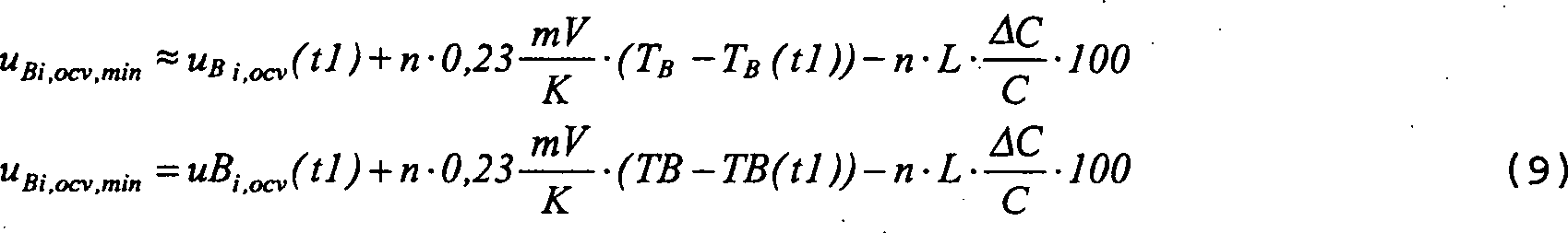
der Beobachtungsperiode.It is assumed that the cell open circuit voltage of a specific i-th monoblock is known at a time t1. If a minimum value u Bi , ocv, min is to be defined, to which the cell open circuit voltage may drop, so that the capacitance of the monoblock is not reduced by more than a certain percentage value (ΔC / C) * 100, a formula can be used for this minimum value can be written based on equations (1) - (8) shown above
Figure 00150001
in which:
U Bi, ocv (t1) = cell open circuit voltage of the i-th monoblock at time tl;
n = number of cells in monoblocks,
T B = temperature of the monoblock at the time of observation,
T B (t1) = the temperature of the block at time t1,
L = constant describing the influence of the percentage change in capacitance on the cell voltage, and
(ΔC / C) · 100 = the maximum allowed percentage loss of capacity during the observation period.

Die Formel (9) gemäß der vorteilhaften Ausführungsform der vorliegenden Erfindung wird für die Definition. der minimalen Spannung UMIN, die in 5 dargestellt ist, verwendet. Da der Akkumulator aus mehreren Monoblöcken besteht, weichen aufgrund von Fertigungstoleranzen und individuellen Eigenschaften deren Zellenleerlaufspannungen leicht ab, weshalb das in 6 dargestellte Verfahren am vorteilhaftesten eingesetzt wird. Dieses Verfahren wird nachstehend im Detail beschrieben.Formula (9) according to the advantageous embodiment of the present invention is used for the definition. the minimum voltage U MIN , which in 5 is shown used. Since the accumulator consists of several monoblocks, their cell open-circuit voltages deviate slightly due to manufacturing tolerances and individual properties, which is why in 6 described method is most advantageously used. This method is described in detail below.

Der Zustand 601 ist der Initialzustand, in welchem die Zellenleerlaufspannung jedes Monoblocks in einem Zustand gemessen wird, in welchem der Akkumulator im wesentlichen voll geladen ist. Somit ist der vorstehend erwähnte Zeitpunkt t1 der fragliche, so dass die Messergebnisse mit uBi,ocv(t1) markiert sind, wobei der Index i so viele Werte annimmt, wie der fragliche Akkumulator Blöcke besitzt. Die Zellenspannung des Bleiakkumulators stabilisiert sich auf ihre tatsächliche Zellenleerlaufspannung nur nach einer bestimmten Zeit (etwa 1 bis 2 Tage), nachdem die vorausgegangene Ladung beendet wurde, so dass es am vorteilhaftesten ist, den Zeitpunkt t1 so zu wählen, so dass wenigstens 24 Stunden nach der Beendigung der vorhergehenden Ladung verstrichen sind. Die am besten geeignete Dauer, welche den Zeitpunkt t1 von dem Beenden der Ladung trennt, kann experimentell gesucht werden.The state 601 is the initial state in which the cell open circuit voltage of each monoblock is measured in a state in which the accumulator is essentially fully charged. Thus, the aforementioned time t1 is the one in question, so that the measurement results are marked with u Bi , ocv (t1), the index i taking on as many values as the accumulator in question has blocks. The cell voltage of the lead accumulator stabilizes to its actual cell open circuit voltage only after a certain time (about 1 to 2 days) after the previous charge has ended, so that it is most advantageous to choose the time t1 so that at least 24 hours after the previous charge has ended. The most suitable duration which separates the time t1 from the end of the charge can be found experimentally.

Zusätzlich wird im Zustand 601 das niedrigste Messergebnis ausgewählt. Es wird angenommen, dass die niedrigste Zellenleerlaufspannung für den j.-ten Block gemessen wurde, wobei in diesem Falle der niedrigste in 601 gewählte Wert mit uBj,ocv(t1) bezeichnet werden kann. Danach wird nur dieser fragliche j.-te Block überwacht.In addition, in the state 601 the lowest measurement result selected. It is assumed that the lowest cell open circuit voltage was measured for the jth block, in which case the lowest in 601 selected value can be denoted by u Bj , ocv (t1). After that, only this questionable jth block is monitored.

Im Zustand 602 wird die Formel (9) verwendet, um einen Minimalwert zu berechnen, auf welchen die Zellenleerlaufspannung fallen darf, so dass die Kapazität nicht kleiner als ein vorbestimmter prozentualer Wert wird. Der spezifische ausgewählte kleinste Wert uBj,ocv(t1) wird in der Formel (9) für die Berechnung des minimalen Wertes ersetzt, so dass der berechnete minimale Wert mit uBj,ocv,min angegeben werden kann. Der Zustand 602 ist ein Teil des Zyklusses, welcher überwacht, wie die Zellenleerlaufspannung seines j.-ten Blockes abnimmt, wobei der j.-te Block der Block mit der Zellenleerlaufspannung ist, welche als die niedrigste in dem Zustand 601 gefunden wurde. Die Zustände 603 und 604 bilden weitere Teile des Zyklus. Der Zyklus wird wiederholt bis die Zellenleerlaufspannung des j.-ten Blockes den im Zustand 602 be rechneten minimalen Wert erreicht, oder bis eine bestimmte maximale Zeit tcmax von der vorherigen Ladung aus abgelaufen ist. Wenn eines dieser Kriterien erfüllt ist, führt es zu dem Zustand 605, in welchem die Ladung des Akkumulators gestartet wird.In condition 602 Formula (9) is used to calculate a minimum value to which the cell open circuit voltage may fall so that the capacitance does not become less than a predetermined percentage value. The specific selected smallest value u Bj , ocv (t1) is replaced in the formula (9) for the calculation of the minimum value, so that the calculated minimum value can be specified with u Bj, ocv, min . The state 602 is part of the cycle that monitors how the cell open voltage of its jth block decreases, the jth block being the block with the cell open voltage, which is considered the lowest in the state 601 was found. The conditions 603 and 604 form further parts of the cycle. The cycle is repeated until the open circuit voltage of the jth block in the state 602 calculated minimum value reached, or until a certain maximum time t cmax from the previous charge has expired. If one of these criteria is met, it leads to the condition 605 , in which the charging of the accumulator is started.

Die vorstehend präsentierte einfache Ausführungsform basiert auf der Überwachung der Abnahme der Zellenleerlaufspannung nur in einem Block. Auch andere Arten von Ausführungsformen können von der vorliegenden Erfindung präsentiert werden. 7 stellt eine Ausführungsform in dem Initialzustand 701 dar, in welchem die Zellenleerlaufspannung jedes Blockes in dem Zeitpunkt gemessen wird, wenn der Akkumulator im wesentlichen voll geladen ist, wobei die vorstehend beschriebene Einstellzeit der Zellenleerlaufspannung berücksichtigt wird. Die Messergebnisse sind wiederum mit uBi, ocv(t1) bezeichnet, wobei der Index i so viele Werte annimmt, wie der fragliche Akkumulator Blöcke besitzt.The simple embodiment presented above is based on monitoring the decrease in cell open circuit voltage in only one block. Other types of embodiments can also be presented by the present invention. 7 represents an embodiment in the initial state 701 represents in which the cell open circuit voltage of each block is measured at the point in time when the accumulator is substantially fully charged, taking into account the setting time of the cell open circuit voltage described above. The measurement results are again designated with u Bi, ocv (t1), the index i taking on as many values as the accumulator in question has blocks.

In der. in 7 dargestellten Ausführungsform wird keinem der Messergebnisse ein Vorzug gegeben, statt dessen wird im Zustand 702 ein individueller Minimalwert für jeden Block unter Verwendung der Formel (9) berechnet, wobei in diesem Falle die Zellenleerlaufspannung so absinken darf, dass die Kapazität nicht kleiner als ein bestimmter definierter prozentualer Teil wird. Für die Berechnung des individuellen minimalen Wertes für jeden Block wird der gemessene Wert der Zellenleerlaufspannung uBi,ocv(t1) in die Formel (9) eingesetzt.In the. in 7 The embodiment shown is given no preference to any of the measurement results; 702 an individual minimum value for each block is calculated using the formula (9), in which case the cell open circuit voltage may drop so that the capacitance does not become smaller than a certain defined percentage. For the calculation of the individual minimum value for each block, the measured value of the cell open circuit voltage u Bi, ocv (t1) is used in the formula (9).

Der Zustand 702 ist wiederum Teil eines Zyklusses, in welchem dieses Mal beobachtet wird, wie die Zellenleerlaufspannung jedes Blockes abnimmt. Die Zustände 703 und 704 bilden die weiteren Teile des Zyklusses Der Zyklus wird wiederholt, bis die Zellenleerlaufspannung eines Blockes den individuellen minimalen Wert erreicht, welcher für jeden Block getrennt. berechnet werden kann, oder bis eine bestimmte maximale Zeit tcmax von der vorherigen Ladung aus verstrichen ist. Wenn eines dieser Kriterien erfüllt ist, führt es zu dem Zustand 705, in welchem die Ladung des Akkumulators gestartet wird.The state 702 is again part of a cycle in which this time it is observed how the open circuit voltage of each block decreases. The conditions 703 and 704 form the other parts of the cycle The cycle is repeated until the open circuit voltage of a block reaches the individual minimum value, which is separate for each block. can be calculated, or until a certain maximum time t cmax has elapsed from the previous charge. If one of these criteria is met, it leads to the condition 705 , in which the charging of the accumulator is started.

Zusätzlich zu den vorstehend beschriebenen Ausführungsformen können Ausführungsformen gemäß der vorliegenden Erfindung präsentiert werden, in welchen für die Berechnung der minimalen Werte und für die Überwachung der individuellen Zellenleerlaufspannungen der unterschiedlichen Blöcke einige Zwischenblockberechnungen angewendet werden. Beispielsweise können die zu beobachtenden Spannungen als Mittel- oder Medianwerte von Zwischenblockspannungen verwendet werden. In diesem Falle geht jedoch ein Teil der Vorzüge des Verfahrens gemäß der vorliegenden Erfindung verloren, da die Information über die einzelnen Blöcke verloren geht.In addition to those described above embodiments can embodiments according to the present Invention presented in which for calculating the minimum values and for monitoring the individual Different blocks some cell open circuit voltages Inter-block calculations can be applied. For example, the voltages to be observed as mean or median values of inter-block voltages be used. In this case, however, some of the advantages of the procedure go according to the present Invention lost because the information about the individual blocks was lost goes.

Nachstehend wird untersucht, wann die Ladung des Akkumulators vorteilhaft zu beenden ist, d. h., wie die Anordnung gemäß der vorliegenden Erfindung in der Nähe der in Fig. 5 dargestellten maximalen Spannung Uc der Ladung funktioniert. 8 stellt eine experimentelle Messung dar, in welcher die Kurve 801 den Wert des Ladestroms iB in Bezug auf den Maximalwert des Ladestroms und die Kurve 802 den Wert der maximalen Differenz Δumax zwischen den Blockspannungen uBi darstellt, welche mathematisch durch die Formel Δumax = maxi1,i2[uBi1 – Bi2]. (10)definiert werden kann.In the following it will be investigated when the charging of the accumulator is to be terminated advantageously, ie how the arrangement according to the present invention is close to that in FIG Fig. 5 shown maximum voltage U c of the charge works. 8th represents an experimental measurement in which the curve 801 the value of the charging current i B in relation to the maximum value of the charging current and the curve 802 represents the value of the maximum difference Δu max between the block voltages u Bi , which is mathematically represented by the formula .DELTA.u Max = max i1, i2 [uB i1 - B i2] , (10) can be defined.

In 8 drückt die horizontale Achse die Zeit aus und die vertikale Achse drückt sowohl den relativen Wert des Ladestroms als auch den Wert der maximalen Differenz der Blockspannungen aus; die Einheiten sind irrelevant. Zu dem Zeitpunkt 803, an dem der vorstehend erwähnte Maximalwert Uc der Ladespannung erreicht wird, beginnt der Ladestrom schnell kleiner zu werden: dessen zeitliche Ableitung (diB/dt) ist hoch und besitzt einen negativen Wert. Zum selben Zeitpunkt steigt der Wert der maximalen Differenz Δumax der Blockspannungen uBi stark an, da die Spannung des ersten voll geladenen Blockes ansteigt und die Spannung der anderen Blöcke entsprechend kleiner wird: Die zeitliche Ableitung (dΔumax/dt) ist ebenfalls hoch und besitzt einen positiven Wert. Wenn die anderen Zellen ihren vollen Zustand erreichen, jede in ihrem Turnus, wird der absolute Wert der zeitlichen Ableitung (diB/dt) des Ladestroms kleiner. Die zeitliche Ableitung (dΔumax/dt) der maximalen Differenz der Blockspannungen verändert sich zuerst ins Negative und kann danach einige Male in beide Richtungen um Null herum oszillieren, beginnt aber am Ende sich stabil an Null anzunähern. Zu dem Zeitpunkt 804 sind beide Ableitungen (diB/dt) und (dΔumax/dt) im wesentlichen Null, d. h., um ihren Absolutwert kleiner als ein bestimmter niedriger Schwellenwert.In 8th the horizontal axis expresses time and the vertical axis expresses both the relative value of the charging current and the value of the maximum difference of the block voltages; the units are irrelevant. At the time 803 , at which the above-mentioned maximum value U c of the charging voltage is reached, the charging current begins to decrease rapidly: its time derivative (di B / dt) is high and has a negative value. At the same time, the value of the maximum difference Δu max of the block voltages u Bi rises sharply, since the voltage of the first fully charged block increases and the voltage of the other blocks decreases correspondingly: the time derivative (dΔu max / dt) is also high and has a positive value. When the other cells reach their full state, each in their cycle, the absolute value of the time derivative (di B / dt) of the charging current becomes smaller. The time derivative (dΔu max / dt) of the maximum difference in the block voltages changes first into negative and can then oscillate around zero a few times in both directions, but in the end begins to steadily approach zero. At the time 804 both derivatives (di B / dt) and (dΔu max / dt) are essentially zero, that is, by their absolute value less than a certain lower threshold value.

Gemäß einer vorteilhaften Ausführungsform der vorliegenden Erfindung wird die Ladung gemäß Darstellung in dem Flussdiagramm von 9 beendet. In dem Zustand 901 wird erkannt, dass die Zeitableitung (diB/dt) einen hohen und negativen Wert hat und die Zeitableitung (dΔumax/dt) einen hohen und positiven Wert hat. Die Schwellenwerte für die Betrachtung der Werte der Zeitableitungen können experimen tell herausgefunden werden. Die Zustände 902 und 903 bilden einen Zyklus dessen Zweck in der Beobachtung der Zeitableitung (dΔumax/dt) der maximalen Differenz der Blockspannungen in aufeinander folgenden Zeitperioden und der Speicherung der Information liegt, wenn diese ihren höchsten Wert erreicht. Wenn diese Information gespeichert worden ist, d. h., keine höheren Werte mehr beobachtet werden, wird in den Zustand 904 eingetreten, in welchem beobachtet wird, wie die Absolutwerte sowohl der zeitlichen Ableitungen (diB/dt) als auch (dΔumax/dt) auf Null abfallen. Die Zustände 904 und 905 bilden einen Zyklus, welcher wiederholt wird, bis beide zeitlichen Ableitungen im wesentlichen Null sind, oder bis eine bestimmte maximale Zeit tmax von dem Zeitpunkt aus verstrichen ist, an dem die zeitliche Ableitung (dΔumax/dt) der maximalen Differenz der Blockspannungen ihren maximalen Wert erreicht hat. Eine Detektion eines positiven Ergebnisses in einem der Zustände 904 und 905 führt zu einem Zustand 906, in welchem die Ladung des Akkumulators beendet wird.According to an advantageous embodiment of the present invention, the charge is shown in the flowchart of FIG 9 completed. In that condition 901 it is recognized that the time derivative (di B / dt) has a high and negative value and the time derivative (dΔu max / dt) has a high and positive value. The threshold values for considering the values of the time derivatives can be found experimentally. The conditions 902 and 903 form a cycle, the purpose of which is to observe the time derivative (dΔu max / dt), the maximum difference in block voltages in successive time periods and to store the information when it reaches its highest value. When this information has been saved, ie, no higher values are observed, it is returned to the state 904 occurred, in which it is observed how the absolute values of both the time derivatives (di B / dt ) and (dΔu max / dt) fall to zero. The conditions 904 and 905 form a cycle which is repeated until both time derivatives are essentially zero, or until a certain maximum time tmax has elapsed from the point in time at which the time derivative (dΔu max / dt) of the maximum difference in the block voltages reaches its maximum value has reached. Detection of a positive result in one of the states 904 and 905 leads to a state 906 , in which the charging of the accumulator is ended.

Es ist möglich, Veränderungen und Zusätze an dem in 9 dargestellten Verfahren vorzunehmen, ohne von dem Prinzip der Erfindung abzuweichen. Beispielsweise ist es möglich, eine Einschränkung zum Beenden des Laden hinzuzufügen, gemäß welcher die Ladung ebenfalls beendet wird, wenn eine bestimmte maximale Zeit verstrichen ist, nachdem sie gestartet wurde, selbst wenn keines der Kriterien gemäß den Zuständen 904 oder 905 erfüllt wird. Zusätzlich kann das Beenden der Ladung von der gemessenen Temperatur des Akkumulators abhängig gemacht werden, so dass das Überschreiten einer gewissen vorbestimmten Schwellenwerttemperatur das Beenden der Ladung bewirkt.It is possible to make changes and additions to the in 9 to carry out the illustrated method without deviating from the principle of the invention. For example, it is possible to add a charge termination constraint, according to which the charge is also ended when a certain maximum time has elapsed after it has started, even if none of the criteria according to the conditions 904 or 905 is fulfilled. In addition, the termination of the charge can be made dependent on the measured temperature of the accumulator, so that exceeding a certain predetermined threshold temperature causes the termination of the charge.

10 ist ein Zustandsdiagramm, welches den Betrieb der elektrischen Hilfsversorgung gemäß der vorliegenden Erfindung beschreibt. Es sind drei Zustände darin definiert, welche der Reservezustand ohne Ladung 1001, der Reservezustand mit Ladung 1002 und der Zustand 1003 sind, in welchem die elektrische Energie aus dem Akkumulator an die Last entladen wird. Gemäß einer vorteilhaften Ausführungsform der Erfindung erfolgt der Übergang vom Zustand 1001 auf den Zustand 1002, wenn eines der Kriterien erfüllt ist, welche vorstehend in Verbindung mit 6 und 7 beschrieben wurden. Dementsprechend erfolgt der Übergang vom Zustand 1002 auf den Zustand 1001, wenn eines der Kriterien erfüllt ist, welche vorstehend in Verbindung mit 8 und 9 beschrieben worden ist. Der Übergang zu dem Zustand 1003 erfolgt als solcher in einer bekannten Weise, wenn der Gleichrichter oder die Gleichrichter, welche als solche nach dem Stand der Technik sein können, aus irgendeinem Grunde die Last nicht mit der elektrischen Energie, die sie benötigt, versorgen kann. Demzufolge kehrt, wenn die Energieversorgungsstörung der Gleichrichter endet, die elektrische Hilfsversorgung in einem als solchem bekannten Weg in den Zustand 1002 zurück, aus welchem der Rücksprung in den Zustand 1001 erfolgt, wenn das Laden gemäß den vorstehend erwähnten Kriterien beendet ist. 10 is a state diagram describing the operation of the auxiliary electrical supply according to the present invention. Three states are defined in it, which are the reserve state without charge 1001 , the reserve state with cargo 1002 and the state 1003 are in which the electrical energy is discharged from the accumulator to the load. According to an advantageous embodiment of the invention, the transition from the state takes place 1001 on the state 1002 , if one of the criteria is met which is described in connection with 6 and 7 have been described. The transition from the state takes place accordingly 1002 on the state 1001 , if one of the criteria is met which is described above in connection with 8th and 9 has been described. The transition to the state 1003 occurs as such in a known manner if the rectifier or rectifiers, which may be prior art as such, for some reason cannot supply the load with the electrical energy which it requires. As a result, when the rectifier power supply failure ends, the auxiliary electrical supply returns to the state in a manner known as such 1002 back, from which the return to the state 1001 takes place when the loading is finished according to the criteria mentioned above.

11 stellt eine Möglichkeit für die Erweiterung der Erfindung für ein System dar, welches mehrere parallelgeschaltete VRLA-Akkumulatoren auf weist. Zwei Akkumulatoren 300' und 300'' sind in der Figur dargestellt, wobei jedoch in der Erfindung die Anzahl der mit dem System verbundenen Akkumulatoren. in keiner Weise beschränkt ist. In dem in 11 dargestellten System wird jeder Akkumulator getrennt in den Messungen behandelt, d. h., die Messung des Ladestroms, die Messung der Temperatur und die Messung der Blockspannun gen werden getrennt für jeden Akkumulator durchgeführt. Die Akkumulatoren sind jedoch für die Ladung parallelgeschaltet, so dass in dem System entweder alle Akkumulatoren geladen werden oder kein Akkumulator geladen wird. Für die vorstehend beschriebenen Ausführungen bedeutet dies, dass, wenn das Kriterium gemäß 6 für den Start der Ladung verwendet wird, der Block des Akkumulators gesucht wird, dessen Zellenleerlaufspannung zu dem Zeitpunkt t1 die niedrigste ist, und die Ladung aller Akkumulatoren gestartet wird, wenn die Zellenleerlaufspannung des fraglichen Blockes den dafür definierten minimalen Wert erreicht. In einer Ausführungsform gemäß Fig. 7 werden die Zellenleerlaufspannungen aller Blöcke in dem gesamten Akkumulatorsystem getrennt überwacht und jede von diesen mit dem für jeden Block individuellen minimalen Wert verglichen. Demzufolge wird, wenn die Ausführungsform gemäß 9 für das Beenden der Ladung angewendet wird, die Ladung beendet, wenn in allen Akkumulatoren die zeitlichen Ableitungen des Ladestroms und der Spannungsdifferenz der Blöcke im wesentlichen Null sind, oder wenn eine minimale Zeit von dem Augenblick an verstrichen ist, an dem hohe Werte der Ableitungen detektiert wurden, oder wenn eine einen bestimmten Schwellenwert überschreitende Temperatur in einem von den Akkumulatoren gemessen wird. 11 represents a possibility for the expansion of the invention for a system which has several VRLA accumulators connected in parallel. Two accumulators 300 ' and 300 '' are shown in the figure, but in the invention, the number of accumulators connected to the system. is in no way limited. In the in 11 shown system, each accumulator is treated separately in the measurements, ie the measurement of the charging current, the measurement of the temperature and the measurement of the block voltages are carried out separately for each accumulator. However, the accumulators are connected in parallel for charging, so that either all accumulators are charged in the system or no accumulator is charged. For the embodiments described above, this means that if the criterion according to 6 is used for the start of the charge, the block of the accumulator is sought, the cell open circuit voltage of which is the lowest at the time t1, and the charging of all the accumulators is started when the cell open circuit voltage of the block in question reaches the minimum value defined therefor. In one embodiment according to FIG. 7 the cell open circuit voltages of all blocks in the entire accumulator system are monitored separately and each of these is compared with the individual minimum value for each block. Accordingly, if the embodiment according to 9 is used to terminate the charge, the charge ends when the time derivatives of the La destroms and the voltage difference of the blocks are substantially zero, or when a minimum time has elapsed from the moment when high values of the derivatives have been detected, or when a temperature exceeding a certain threshold value is measured in one of the accumulators.

In einem aus mehreren Akkumulatoren bestehenden System können die Akkumulatoren auch unter Verwendung individueller Schalteinrichtungen mit dem IBCM-Modul verbunden werden, wobei in diesem Falle jeder Akkumulator nach Bedarf. getrennt geladen werden kann. In diesem Falle kann der Aufbau des IBCM-Moduls sehr kompliziert sein. Die Ausführungsform in 11 kann so vereinfacht werden, dass der Ladestrom nicht getrennt für jeden Akkumulator sondern der Ladestrom des gesamten Akkumulatorsystems gemessen wird.In a system consisting of several accumulators, the accumulators can also be connected to the IBCM module using individual switching devices, in which case each accumulator as required. can be loaded separately. In this case, the structure of the IBCM module can be very complicated. The embodiment in 11 can be simplified in such a way that the charging current is not measured separately for each accumulator, but rather the charging current of the entire accumulator system.

Vorstehend wurden nur diejenigen Systeme behandelt, in welchen die Messung und das Verfolgen von Spannungs- und Stromwerten, welche den Zustand des Akkumulatorsystems beschreiben, lokal im wesentlichen in derselben Einheit durchgeführt wird, welche, falls erforderlich, den Akkumulator mit der Ladeversorgung verbindet und diesen von der Versorgung trennt. Die Erfindung kann auch so angewendet werden, dass der Zustand des Akkumulatorsystems überwacht werden kann und die Schaltbefehle zusätzlich zu oder anstelle der lokalen Einheit über ein Fernsteuersystem gegeben werden können. In diesem Falle ist kein weiteres Gerät in einer Verbindung mit dem Akkumulatorsystem, bis auf die Messelemente, Schalter und das telemetrische Gerät, mittels welchen die Messergebnisse übertragen werden und die Schaltbefehle empfangen werden, wie z. B. über das Internet oder Telefonnetz, erforderlich.Above were only those Deals with systems in which the measurement and tracking of voltage and current values that describe the state of the battery system, is carried out locally in essentially the same unit, which, if necessary, the accumulator with the charging supply connects and separates this from the supply. The invention can also be applied so that the status of the battery system is monitored can be and the switching commands in addition to or instead of local unit over a remote control system can be given. In this case there is none another device in connection with the accumulator system, except for the measuring elements, Switches and the telemetric device by means of which the measurement results are transmitted and the switching commands are received, such as. B. about that Internet or telephone network, required.

Die Merkmale der vorstehend beschriebenen Erfindung können in vielen unterschiedlichen Arten zusammen oder getrennt angewendet werden. D. h., es ist möglich das vorstehend beschriebene Verfahren gemäß der Erfindung nur für den Start der Ladung des Akkumulators zu verwenden und die Ladung nach einer bestimmten konstanten Ladezeit zu beenden, oder wenn die maximale Ladespannung erreicht worden ist. Andererseits kann das Laden des Akkumulators gemäß einem anderen Kriterium gestartet werden und das vorstehend beschriebene Verfahren gemäß der Erfindung nur für das Beenden der Ladung des Akkumulators angewendet werden. Das vorteilhafteste Ergebnis kann jedoch erzielt werden, wenn die Erfindung sowohl für das Starten der Ladung als auch für das Beenden der Ladung angewendet wird.The characteristics of those described above Invention can applied together or separately in many different ways become. That is, it is possible the method described above according to the invention only for the start the charge of the accumulator to use and the charge after a certain end constant charging time, or when the maximum charging voltage has been achieved. On the other hand, charging the battery according to one other criteria are started and the one described above Method according to the invention only for terminating the charging of the accumulator can be applied. The most beneficial However, result can be achieved if the invention is both for starting the cargo as well for loading termination is applied.

Claims (14)

Eine elektrische Hilfsversorgung zum Sicherstellen der Energie für eine bestimmte Last umfassend: – einen Akkumulator (300, 300', 300''), bestehend aus Blöcken (301, 302, 303, 304), – die Schalteinrichtung (402) zum bedingten Verbinden des Akkumulators mit der Last oder mit der Ladestromversorgung, – Mess- und Kontrolleinrichtungen (403) zum Erzeugen von Messergebnissen zum Beschreiben des Zustandes des Akkumulators und zum Kontrollieren der Schalteinrichtung (402) auf der Basis der erzeugten Messergebnisse; dadurch gekennzeichnet, dass die Mess- und Kontrolleinrichtungen (403) angeordnet sind, – um den blockspezifischen Initialwert (uBi,ocv(t1)) der Zellenleerlaufspannung von einem geladenen Akkumulator zu messen, – um aus dem gemessenen blockspezifischen Initialwert der Zellenleerlaufspannung einen bestimmten Schwellwert (uBi,ocv,min) zu erzeugen, – um den gemessenen blockspezifischen Zellenleerlaufspannungswert (uBi) mit dem Schwellwert zu vergleichen, und – um in einer Reaktion auf die Beobachtung, gemäß welcher die gemessene Zellenleerlaufspannung eines Blocks den Schwellwert erreicht hat, die Schalteinrichtung (402) zu kontrollieren, um den Akkumulator (300, 300', 300'') mit einer bestimmten Ladestromversorgung zu verbinden.An auxiliary electrical supply to ensure the energy for a specific load comprises: - an accumulator ( 300 . 300 ' . 300 '' ) consisting of blocks ( 301 . 302 . 303 . 304 ), - the switching device ( 402 ) for the conditional connection of the accumulator to the load or to the charging power supply, - measuring and control devices ( 403 ) for generating measurement results for describing the state of the accumulator and for checking the switching device ( 402 ) on the basis of the measurement results generated; characterized in that the measuring and control devices ( 403 ) are arranged - to measure the block-specific initial value (u Bi , ocv (t1)) of the cell open circuit voltage from a charged accumulator - to generate a certain threshold value (u Bi , ocv , min ) from the measured block-specific initial value of the cell open circuit voltage - in order to compare the measured block-specific cell open circuit voltage value (u Bi ) with the threshold value, and - in response to the observation according to which the measured cell open circuit voltage of a block has reached the threshold value, the switching device ( 402 ) to check the accumulator ( 300 . 300 ' . 300 '' ) to be connected to a specific charging power supply. Eine elektrische Hilfsversorgung gemäß Anspruch 1, dadurch gekennzeichnet, dass die Mess- und Kontrolleinrichtungen (403) zusätzlich angeordnet sind, um – den Wert der Veränderung. des Ladestroms im Verhältnis zur Zeit (diB/dt) zu messen, – den Wert der Veränderung der Spannungsdifferenz zwischen den Blöcken im Verhältnis zur Zeit (dΔumax/dt) zu messen, und – als eine Reaktion auf die Beobachtung, gemäß welcher der Wert der Veränderung des Ladestroms im Verhältnis zur Zeit (diB/dt) von dem negativen Grenzwert im Wesentlichen zu Null zurückgekehrt ist und der Wert der Veränderung der Spannungsdifferenz zwischen den Blöcken im Verhältnis zur Zeit (dΔumax/dt) von dem positiven Grenzwert im Wesentlichen zu Null zurückgekehrt ist, die Schalteinrichtung (402) zu kontrollieren, um den Akkumulator (300, 300', 300'') von der Ladestromversorgung zu trennen.An auxiliary electrical supply according to claim 1, characterized in that the measuring and control devices ( 403 ) are additionally arranged to - the value of the change. of the charging current versus time (di B / dt), - measure the value of the change in voltage difference between the blocks versus time (dΔu max / dt), and - as a response to the observation according to which the The value of the change in the charging current in relation to time (di B / dt) has essentially returned to zero from the negative limit value and the value of the change in voltage difference between the blocks in relation to time (dΔu max / dt) from the positive limit value in Has essentially returned to zero, the switching device ( 402 ) to check the accumulator ( 300 . 300 ' . 300 '' ) from the charging power supply. Eine elektrische Hilfsversorgung gemäß Anspruch 1, dadurch gekennzeichnet, dass die Schalteinrichtung (402) angeordnet ist, um den Akkumulator mit einer Ladestromversorgung bedingt zu verbinden, welche die gleiche wie die Stromversorgung ist, welche angeordnet ist, um elektrische Energie der besagten Last zuzuführen.An auxiliary electrical supply according to claim 1, characterized in that the switching device tung ( 402 ) is arranged to conditionally connect the accumulator to a charging power supply which is the same as the power supply which is arranged to supply electrical energy to said load. Eine elektrische Hilfsversorgung gemäß Anspruch 1, dadurch gekennzeichnet, dass die Schalteinrichtung (402)angeordnet ist, um den Akkumulator mit einer Ladestromversorgung bedingt zu verbinden, welche nicht mit der Stromversorgung, die angeordnet ist, um die besagte mit elektrischer Energie zu versorgen, identisch ist.An auxiliary electrical supply according to claim 1, characterized in that the switching device ( 402 ) is arranged to conditionally connect the accumulator to a charging power supply which is not identical to the power supply which is arranged to supply said electrical energy. Eine elektrische Hilfsversorgung zum Sicherstellen der Energie für eine bestimmte Last, umfassend – einen Akkumulator (300, 300', 300'') bestehend aus Blöcken (301, 302, 303, 304), – die Schalteinrichtung (402) zum bedingten Verbinden des Akkumulators mit der Last oder der Ladestromversorgung, – Mess- und Kontrolleinrichtungen (403) zum Erzeugen. von Messergebnissen zum Beschreiben des Status des Akkumulators und zum Kontrollieren der Schalteinrichtung (402) auf der Basis der erzeugten Messergebnisse; dadurch gekennzeichnet, dass die Mess- und Kontrolleinrichtungen (403) angeordnet sind, um – den Wert der Veränderung des Ladestroms im Verhältnis zur Zeit (diB/dt) zu messen, – den Wert der Veränderung der Spannungsdifferenz zwischen den Blöcken im Verhältnis zur Zeit (dΔumax/dt) zu messen, und – in einer Reaktion auf die Beobachtung, gemäß welcher der Wert der Veränderung des Ladestroms im Verhältnis zur Zeit (diB/dt) von einem negativen Grenzwert im Wesentlichen zu Null zurückgekehrt ist und der Wert der Veränderung der Spannungsdifferenz zwischen den Blöcken im Verhältnis zur Zeit (dΔumax/dt) von dem positiven Grenzwert im Wesentlichen zu Null zurückgekehrt ist, die Schalteinrichtung (402) zu kontrollieren, um den Akkumulator (300, 300', 300'') von einer bestimmten Ladestromversorgung zu trennen.An auxiliary electrical supply to ensure the energy for a specific load, comprising - an accumulator ( 300 . 300 ' . 300 '' ) consisting of blocks ( 301 . 302 . 303 . 304 ), - the switching device ( 402 ) for the conditional connection of the accumulator to the load or the charging power supply, - measuring and control devices ( 403 ) to generate. of measurement results for describing the status of the accumulator and for checking the switching device ( 402 ) on the basis of the measurement results generated; characterized in that the measuring and control devices ( 403 ) are arranged in order to - measure the value of the change in the charging current in relation to time (di B / dt), - measure the value of the change in the voltage difference between the blocks in relation to time (dΔu max / dt), and - in response to the observation that the value of the change in charge current versus time (di B / dt) has substantially returned from a negative limit and the value of the change in voltage difference between the blocks versus time ( dΔu max / dt) has essentially returned to zero from the positive limit value, the switching device ( 402 ) to check the accumulator ( 300 . 300 ' . 300 '' ) from a specific charging power supply. Ein Verfahren zum Kontrollieren einer elektrischen Hilfsversorgung, die einen Akkumulator (300, 300', 300'') bestehend aus Blöcken (301, 302, 303, 304) umfasst, dadurch gekennzeichnet, dass das Verfahren die Zustände umfasst, in welchen – ein blockspezifischer Initialwert der Zellenleerlaufspannung von dem geladenen Akkumulator gemessen wird (601, 701), – ein bestimmter Schwellwert aus dem gemessenen blockspezifischen Initialwert der Zellenleerlaufspannung erzeugt wird (602, 702), – der gemessene blockspezifische Wert der Zellenleerlaufspannung mit dem Schwellwert verglichen wird (603, 703), und – in einer Reaktion auf die Beobachtung, gemäß welcher der gemessene blockspezifische Wert der Zellenleerlaufspannung den Schwellwert erreicht hat, der Ladestrom mit dem Akkumulator verbunden wird (605, 705).A method of controlling an auxiliary electrical supply that includes an accumulator ( 300 . 300 ' . 300 '' ) consisting of blocks ( 301 . 302 . 303 . 304 ), characterized in that the method comprises the states in which - a block-specific initial value of the cell open circuit voltage is measured by the charged accumulator ( 601 . 701 ), - a certain threshold value is generated from the measured block-specific initial value of the cell open circuit voltage ( 602 . 702 ), - the measured block-specific value of the cell open circuit voltage is compared with the threshold value ( 603 . 703 ), and - in response to the observation according to which the measured block-specific value of the cell open circuit voltage has reached the threshold value, the charging current is connected to the accumulator ( 605 . 705 ). Ein Verfahren gemäß Anspruch 6, dadurch gekennzeichnet, dass – der Initialwert der Zellenleerlaufspannung von jedem Block getrennt gemessen wird (601), – der kleinste der gemessenen blockspezifischen Initialwerte der Zellenleerlaufspannungen selektiert wird (601), – ein Schwellwert für irgendeine gegebene Zeit erzeugt wird (602), und zwar des kleinsten selektierten blockspezifischen Initialwertes der Zellenleerlaufspannung, welcher der Initialwert der Zellenleerlaufspannung minus des ersten Spannungswertes ist, der dem maximal erlaubten Verlust an Kapazität des Blocks entspricht, der aus der Entladung resultiert und korrigiert ist durch einen anderen Spannungswert, der der Zellenleerlaufspannungsveränderung entspricht, die aus der Temperaturveränderung resultiert, – der Zellenleerlaufspannungswert, der mit dem Schwellwert verglichen wird (603) von demselben Block gemessen wird, von dem der Schwellwert auf der Basis des Initialwertes der Zellenleerlaufspannung erzeugt wird.A method according to claim 6, characterized in that - the initial value of the cell open circuit voltage of each block is measured separately ( 601 ), - the smallest of the measured block-specific initial values of the open circuit voltages is selected ( 601 ), - a threshold is generated for any given time ( 602 ), namely the smallest selected block-specific initial value of the open circuit voltage, which is the initial value of the open circuit voltage minus the first voltage value, which corresponds to the maximum allowable loss of capacity of the block, which results from the discharge and is corrected by another voltage value, that of the open circuit voltage change , which results from the temperature change, - the cell open-circuit voltage value, which is compared with the threshold value ( 603 ) is measured from the same block from which the threshold value is generated on the basis of the initial value of the cell open circuit voltage. Ein Verfahren gemäß Anspruch 7, dadurch gekennzeichnet, dass der Schwellwert für irgendeine gegebene Zeit erzeugt wird durch die Formel
Figure 00280001
in welcher uBi,ocv(t1) Zellenleerlaufspannung des i'ten Monoblocks zum Zeitpunkt t1; n = Anzahl von Zellen in Monoblöcken, TB = die Temperatur des Monoblocks zum Zeitpunkt der Beobachtung; TB(t1) = die Temperatur des Blocks zum Zeitpunkt t1, L = Konstante, die den Einfluss der prozentualen Veränderung der Kapazität auf die Zellspannung beschreibt, und (ΔC/C) 100 = der maximal erlaubte prozentuale Verlust von Kapazität während der Beobachtungsperiode ist.
A method according to claim 7, characterized in that the threshold is generated for any given time by the formula
Figure 00280001
in which u Bi, ocv (t1) open circuit voltage of the i'th monoblock at time t1; n = number of cells in monoblocks, T B = the temperature of the monoblock at the time of observation; T B (t1) = the temperature of the block at time t1, L = constant describing the influence of the percentage change in capacitance on the cell voltage, and (ΔC / C) 100 = the maximum allowed percentage loss of capacity during the observation period ,
Ein Verfahren gemäß Anspruch 6, dadurch gekennzeichnet, das der blockspezifische Initialwert der Zellenleerlaufspannung wenigstens nach 24 Stunden nachdem das vorherige Laden des Akkumulators beendet worden ist, gemessen wird (601).A method according to claim 6, characterized in that the block-specific initial value of the cell open circuit voltage is measured at least 24 hours after the previous charging of the accumulator has ended ( 601 ). Ein Verfahren gemäß Anspruch 6, dadurch gekennzeichnet, dass – der Initialwert der Zellenleerlaufspannung von jedem Block von dem geladenen Akkumulator getrennt gemessen wird (701), – der Schwellwert für irgendeine gegebene Zeit für jeden Block aus dem Initialwert der Zellenleerlaufspannung jedes Blocks erzeugt wird (702), welcher der Initialwert der Zellenleerlaufspannung des besagten Blocks minus des ersten Spannungswertes ist, der dem maximal erlaubten Abfall von Kapazität des Blocks entspricht, der aus der Entladung resultiert und korrigiert ist durch einen anderen Spannungswert, der der Zellenleerlaufspannungsveränderung resultierend aus der Temperaturveränderung entspricht, – der Zellenleerlaufspannungswert, der mit dem Schwellwert verglichen wird, separat von jedem Block gemessen wird (703), die gemessene Zellenleerlaufspannung anschließend mit dem Schwellwert verglichen wird, der auf der Basis des Initialwertes der Zellenleerlaufspannung des gleichen Blocks erzeugt ist.A method according to claim 6, characterized in that - the initial value of the cell open circuit voltage of each block is measured separately from the charged accumulator ( 701 ), - the threshold for any given time for each block is generated from the initial value of the open circuit voltage of each block ( 702 ), which is the initial value of the open circuit voltage of the said block minus the first voltage value, which corresponds to the maximum permitted decrease in the capacitance of the block, which results from the discharge and is corrected by another voltage value, which corresponds to the change in the open circuit voltage resulting from the temperature change, the cell open circuit voltage value, which is compared to the threshold value, is measured separately from each block ( 703 ), the measured cell open circuit voltage is then compared with the threshold value which is generated on the basis of the initial value of the cell open circuit voltage of the same block. Ein Verfahren gemäß Anspruch 6, dadurch gekennzeichnet, dass das Verfahren zusätzlich eine Phase umfasst, in welcher als ein Ergebnis der Beobachtung (604, 704), gemäß welcher die seit einer vorhergehenden Ladung verstrichene Zeit eine bestimmte maximale Zeit erreicht hat, ein Ladestrom mit dem Akkumulator verbunden wird (605, 705).A method according to claim 6, characterized in that the method additionally comprises a phase in which, as a result of the observation ( 604 . 704 ), according to which the time elapsed since a previous charge has reached a certain maximum time, a charging current is connected to the accumulator ( 605 . 705 ). Ein Verfahren gemäß Anspruch 6, dadurch gekennzeichnet, dass das verfahren zusätzlich Phasen umfasst, in welchen – der Wert der Ladestromveränderung im Verhältnis zur Zeit gemessen wird (901), – der Wert der Veränderung der Spannungsdifferenz zwischen den Blöcken im Verhältnis zur Zeit gemessen wird (901), – als eine Reaktion auf die Beobachtung (904), gemäß welcher der Wert der Veränderung des Ladestroms im Verhältnis zur Zeit von dem negativen Grenzwert im Wesentlichen zu Null zurückgekehrt ist und der Wert der Veränderung der Spannungsdifferenz zwischen den Blöcken von dem positiven Grenzwert im Wesentlichen zu Null zurückgekehrt ist, der Akkumulator von dem Ladestrom getrennt wird (906).A method according to claim 6, characterized in that the method additionally comprises phases in which - the value of the charge current change is measured in relation to time ( 901 ), - the value of the change in the voltage difference between the blocks in relation to time is measured ( 901 ), - as a reaction to the observation ( 904 ), according to which the value of the change in the charging current relative to time has substantially returned from the negative limit and the value of the change in voltage difference between the blocks has returned from the positive limit substantially to zero, the accumulator from the charging current is separated ( 906 ). Ein Verfahren zum Kontrollieren des Betriebs einer elektrischen Hilfsversorgung umfassend einen Akkumulator, der aus Blöcken besteht, dadurch gekennzeichnet, dass das verfahren Phasen umfasst, in welchen – der Wert der Ladestromveränderung im Verhältnis zur Zeit gemessen wird (901), der Wert der Veränderung der Spannungsdifferenz zwischen den Blöcken im Verhältnis zur Zeit gemessen wird (901), – als eine Reaktion auf die Beobachtung (904), gemäß welcher der Wert der Veränderung des Ladestroms im Verhältnis zur Zeit von dem negativen Grenzwert im Wesentlichen zu Null zurückgekehrt ist und der Wert der Veränderung der Spannungsdifferenz zwischen den Blöcken im Verhältnis zur Zeit von dem positiven Grenzwert im Wesentlichen zu Null zurückgekehrt ist, der Akkumulator von dem Ladestrom getrennt wird (906).A method for controlling the operation of an electrical auxiliary supply comprising an accumulator consisting of blocks, characterized in that the method comprises phases in which - the value of the change in charging current in relation to time is measured ( 901 ), the value of the change in voltage difference between the blocks in relation to time is measured ( 901 ), - as a reaction to the observation ( 904 ), according to which the value of the change in charge current relative to time has substantially returned from the negative limit and the value of the change in voltage difference between the blocks has returned substantially from zero to the positive limit, which Battery is separated from the charging current ( 906 ). Ein Verfahren gemäß Anspruch 13, dadurch gekennzeichnet, dass das Verfahren zusätzlich eine Phase umfasst, in welcher als eine Reaktion auf die Beobachtung (905), gemäß welcher der Wert der Veränderung der Spannungsdifferenz zwischen den Blöcken im Verhältnis zur Zeit von dem vorstehend erwähnten positiven Grenzwert zurückgekehrt ist, die verstrichene Zeit einen bestimmten Maximalwert erreicht hat, der Akkumulator von dem Ladestrom getrennt wird (906).A method according to claim 13, characterized in that the method additionally comprises a phase in which, as a reaction to the observation ( 905 ) according to which the value of the change in voltage difference between the blocks in relation to time has returned from the positive limit mentioned above, the elapsed time has reached a certain maximum value, the accumulator is disconnected from the charging current ( 906 ).
DE60003581T 1999-11-05 2000-11-03 UNINTERRUPTIBLE POWER SUPPLY (UPS) WITH A CONTROL DEVICE FOR CHARGING A BATTERY AND METHOD FOR CHARGING Expired - Lifetime DE60003581T2 (en)

Applications Claiming Priority (3)

Application Number Priority Date Filing Date Title
FI992396A FI118197B (en) 1999-11-05 1999-11-05 Spare system and method for controlling the operation of the reserve system
FI992396 1999-11-05
PCT/FI2000/000962 WO2001033690A1 (en) 1999-11-05 2000-11-03 Standby electric supply and a method for controlling the operation of a standby electric supply

Publications (2)

Publication Number Publication Date
DE60003581D1 DE60003581D1 (en) 2003-07-31
DE60003581T2 true DE60003581T2 (en) 2004-04-22

Family

ID=8555566

Family Applications (1)

Application Number Title Priority Date Filing Date
DE60003581T Expired - Lifetime DE60003581T2 (en) 1999-11-05 2000-11-03 UNINTERRUPTIBLE POWER SUPPLY (UPS) WITH A CONTROL DEVICE FOR CHARGING A BATTERY AND METHOD FOR CHARGING

Country Status (5)

Country Link
US (1) US7015699B1 (en)
EP (1) EP1238453B1 (en)
DE (1) DE60003581T2 (en)
FI (1) FI118197B (en)
WO (1) WO2001033690A1 (en)

Cited By (1)

* Cited by examiner, † Cited by third party
Publication number Priority date Publication date Assignee Title
DE102013225243A1 (en) 2013-12-09 2015-06-11 Robert Bosch Gmbh A method for transmitting a minimum and / or a maximum value of a battery system parameter and battery system for carrying out such a method

Families Citing this family (6)

* Cited by examiner, † Cited by third party
Publication number Priority date Publication date Assignee Title
US6555991B1 (en) * 2002-02-05 2003-04-29 Andrew Michael Zettel Battery operating condition dependent method and apparatus for controlling energy transfer between an energy bus and a system of batteries
US6909200B2 (en) 2002-02-28 2005-06-21 Azure Dynamics Inc. Methods of supplying energy to an energy bus in a hybrid electric vehicle, and apparatuses, media and signals for the same
JP5448408B2 (en) * 2008-10-15 2014-03-19 三菱重工業株式会社 Secondary battery control system
TWI448886B (en) * 2011-07-28 2014-08-11 Quanta Comp Inc Rack server system and control method thereof
JP2015092816A (en) * 2014-11-28 2015-05-14 日本電気株式会社 Power system, power control method, power control device and program
US10957445B2 (en) 2017-10-05 2021-03-23 Hill-Rom Services, Inc. Caregiver and staff information system

Family Cites Families (13)

* Cited by examiner, † Cited by third party
Publication number Priority date Publication date Assignee Title
US4473756A (en) * 1983-05-23 1984-09-25 Caloyeras, Inc. AC Uninterruptible power system
SE439082B (en) 1984-09-19 1985-05-28 Wahlstroem Tommy METHOD OF CYCLEIC MAINTENANCE CHARGING A CHARGABLE FOR EMERGENCY OPERATION DEPOSIT BATTERY
US4629965A (en) 1985-02-26 1986-12-16 General Battery Corporation Battery charger termination circuit
US4742290A (en) 1986-06-02 1988-05-03 Acme Electric Corporation Recharging battery charger
KR920009364B1 (en) 1990-09-19 1992-10-15 주식회사 금성사 Device for controlling charge
US5206578A (en) 1991-10-15 1993-04-27 Norvik Technologies Inc. Monitoring system for batteries during charge and discharge
GB2261735A (en) * 1991-11-20 1993-05-26 Chloride Silent Power Ltd Battery monitoring and management system
FR2722336B1 (en) 1994-07-08 1996-08-23 Europ Accumulateurs METHOD FOR MAINTAINING THE CHARGE OF A BATTERY AND MONITORING ITS RESIDUAL CAPACITY, ITS CHARGE AND ITS AGING
JPH08140206A (en) * 1994-11-09 1996-05-31 Fuji Heavy Ind Ltd Battery managing method for electric motor vehicle
US5581170A (en) 1994-12-12 1996-12-03 Unitrode Corporation Battery protector
JPH08265987A (en) * 1995-03-20 1996-10-11 Integuran Kk Charging voltage distributor for series battery
JP3099181B2 (en) * 1996-09-10 2000-10-16 本田技研工業株式会社 Battery voltage control device
JPH11234916A (en) * 1998-02-16 1999-08-27 Rohm Co Ltd Lithium ion battery pack

Cited By (2)

* Cited by examiner, † Cited by third party
Publication number Priority date Publication date Assignee Title
DE102013225243A1 (en) 2013-12-09 2015-06-11 Robert Bosch Gmbh A method for transmitting a minimum and / or a maximum value of a battery system parameter and battery system for carrying out such a method
US10490863B2 (en) 2013-12-09 2019-11-26 Robert Bosch Gmbh Method for transferring a minimum and/or a maximum value of a battery system parameter and battery system for carrying out such a method

Also Published As

Publication number Publication date
WO2001033690A1 (en) 2001-05-10
US7015699B1 (en) 2006-03-21
FI118197B (en) 2007-08-15
FI19992396A (en) 2001-05-06
EP1238453A1 (en) 2002-09-11
DE60003581D1 (en) 2003-07-31
EP1238453B1 (en) 2003-06-25

Similar Documents

Publication Publication Date Title
EP3701584B1 (en) Method for charging or discharging an energy store
DE112016002218T5 (en) Control device, electrical storage device and electrical storage system
DE69836403T2 (en) Method of charge control and charger for rechargeable battery
DE102014221547A1 (en) Method for monitoring the state of charge of a battery
DE112011104434T5 (en) Battery control device and battery control method
DE10035959A1 (en) Method of discharging a variety of rechargeable batteries and battery assembly
DE112018006386T5 (en) Apparatus for estimating the economic efficiency of a rechargeable battery and method for estimating the economic efficiency
DE102012110555B4 (en) Combined PI control and pre-control process for cell state of charge balancing
EP3017521B1 (en) Device and method for charge equalization of an energy accumulator arrangement
DE102009003345A1 (en) System and method for estimating the state of charge of an electrochemical energy store
EP2313287A2 (en) Charge status detection for an electrical accumulator
DE102013108198B4 (en) Method for performing cell balancing of a battery system based on capacity values
DE112017003472T5 (en) BATTERY CONTROL DEVICE, BATTERY SYSTEM AND VEHICLE
DE102019211913A1 (en) Method for determining an aging condition of a battery, control unit and vehicle
DE112019005193T5 (en) ELECTRIC STORAGE SYSTEM
DE102013201221A1 (en) Drive device for an electrical energy storage system
DE60003581T2 (en) UNINTERRUPTIBLE POWER SUPPLY (UPS) WITH A CONTROL DEVICE FOR CHARGING A BATTERY AND METHOD FOR CHARGING
WO2019020303A1 (en) Device and method for balancing an energy storage module
DE102015226250B4 (en) Power saving device
EP3618219B1 (en) Method for restoring an over-discharged battery module and corresponding uninterruptable power supply system
DE102014221549B4 (en) Method for monitoring the state of charge of a battery
WO2007003460A1 (en) Method for identifying preset values of an electric accumulator
EP3168957B1 (en) Method and device for the power management of an energy store for preventing micro cycles
EP3408921B1 (en) Determining the capacitance of an energy store of an uninterruptible direct current supply unit
DE102019126692A9 (en) Method for charging and discharging a rechargeable energy storage and energy storage system

Legal Events

Date Code Title Description
8364 No opposition during term of opposition
8327 Change in the person/name/address of the patent owner

Owner name: DELTA ENERGY SYSTEMS (SWITZERLAND) AG, BERN, CH