DE4300373C5 - Magnetic sensor transducer and method for its production - Google Patents
Magnetic sensor transducer and method for its production Download PDFInfo
- Publication number
- DE4300373C5 DE4300373C5 DE4300373A DE4300373A DE4300373C5 DE 4300373 C5 DE4300373 C5 DE 4300373C5 DE 4300373 A DE4300373 A DE 4300373A DE 4300373 A DE4300373 A DE 4300373A DE 4300373 C5 DE4300373 C5 DE 4300373C5
- Authority
- DE
- Germany
- Prior art keywords
- iron core
- sensor arrangement
- sensor
- around
- mold cavity
- Prior art date
- Legal status (The legal status is an assumption and is not a legal conclusion. Google has not performed a legal analysis and makes no representation as to the accuracy of the status listed.)
- Expired - Lifetime
Links
Classifications
-
- G—PHYSICS
- G01—MEASURING; TESTING
- G01R—MEASURING ELECTRIC VARIABLES; MEASURING MAGNETIC VARIABLES
- G01R33/00—Arrangements or instruments for measuring magnetic variables
- G01R33/02—Measuring direction or magnitude of magnetic fields or magnetic flux
-
- G—PHYSICS
- G01—MEASURING; TESTING
- G01R—MEASURING ELECTRIC VARIABLES; MEASURING MAGNETIC VARIABLES
- G01R33/00—Arrangements or instruments for measuring magnetic variables
-
- Y—GENERAL TAGGING OF NEW TECHNOLOGICAL DEVELOPMENTS; GENERAL TAGGING OF CROSS-SECTIONAL TECHNOLOGIES SPANNING OVER SEVERAL SECTIONS OF THE IPC; TECHNICAL SUBJECTS COVERED BY FORMER USPC CROSS-REFERENCE ART COLLECTIONS [XRACs] AND DIGESTS
- Y10—TECHNICAL SUBJECTS COVERED BY FORMER USPC
- Y10T—TECHNICAL SUBJECTS COVERED BY FORMER US CLASSIFICATION
- Y10T29/00—Metal working
- Y10T29/49—Method of mechanical manufacture
- Y10T29/49002—Electrical device making
- Y10T29/4902—Electromagnet, transformer or inductor
- Y10T29/49073—Electromagnet, transformer or inductor by assembling coil and core
Landscapes
- Physics & Mathematics (AREA)
- Condensed Matter Physics & Semiconductors (AREA)
- General Physics & Mathematics (AREA)
- Measuring Magnetic Variables (AREA)
Abstract
Verfahren
zur Herstellung eines Magnetsensor-Aufnehmers, mit folgenden Schritten:
(a)
Zusammenbau einer Sensoranordnung (11) aus einem Magneten (13),
einem Eisenkern (14) und einer Aufnehmerspule (15) in einer Halterungseinheit
(16, 20), die mit einer Positionierausnehmung (23) versehen ist,
wobei ein Ende (14a) des Eisenkerns (14) aus der Halterungseinheit (16,
20) nach außen
vorspringt,
(b1) Einbringen der Sensoranordnung (11) in einen
Formhohlraum (25) einer Form (26, 27),
(b2) wobei das vorspringende
Ende (14a) des Eisenkerns (14) in eine Ausnehmung (28) der Form
(26, 27) eingesetzt wird, und
(b3) ein Positionierstift (30)
der Form (26, 27) in die Positionierausnehmung (23) der Halterungseinheit
(16, 20) eingesetzt wird um die Sensoranordnung (11) zu positionieren und
während
des Spritzgußvorgangs
zu haltern, und
(c) Füllen
des Formhohlraums (25) mit Spritzgußkunststoff zur Ausbildung
eines Außenge
häuses
(12) für
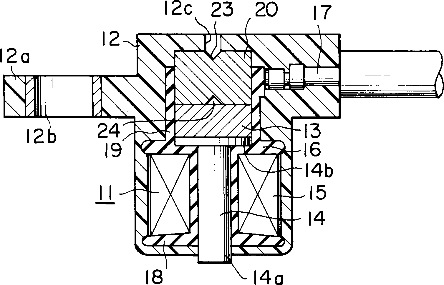
die Sensoranordnung (11).Method for manufacturing a magnetic sensor transducer, with the following steps:
(a) assembling a sensor arrangement (11) from a magnet (13), an iron core (14) and a pick-up coil (15) in a mounting unit (16, 20) which is provided with a positioning recess (23), one end ( 14a) of the iron core (14) projects outwards from the mounting unit (16, 20),
(b1) introducing the sensor arrangement (11) into a mold cavity (25) of a mold (26, 27),
(b2) the projecting end (14a) of the iron core (14) being inserted into a recess (28) in the mold (26, 27), and
(b3) a positioning pin (30) of the mold (26, 27) is inserted into the positioning recess (23) of the mounting unit (16, 20) in order to position the sensor arrangement (11) and to hold it during the injection molding process, and
(C) filling the mold cavity (25) with injection molded plastic to form an outer housing (12) for the sensor arrangement (11).
Description
Die
vorliegende Erfindung betrifft ein Verfahren zur Herstellung eines
Magnetsensor-Aufnehmers. Bei dem aus der
In
der
In
der
In einem ersten Formgebungsschritt wird der Rahmenkörper hergestellt, und in einem zweiten Formgebungsschritt wird ein Formkörper aus Kunstharz ausgebildet welcher die Bauteile und den Rahmenkörper umschließt. Zu diesem Zweck wird der Rahmenkörper mit den darauf angeordneten Bauteilen in eine Form eingeführt, die ein Oberteil und ein Unterteil aufweist. Im Oberteil der Form ist ein vorspringender Abschnitt vorgesehen, der dazu dient, daß bei der Ausbildung des Formkörpers ein Spalt in dem Magnetsensor-Aufnehmer ausgebildet wird. Hierzu berührt der vorspringende Abschnitt die Platte nur an einer von deren Oberflächen. Eine derartige Anordnung ist instabil, da der Rahmenkörper einfach abkippen kann, so daß die Berührung zwischen dem vorspringenden Abschnitt der oberen Formhälfte und der Oberfläche der Platte gelöst werden kann. Der gesamte Bodenabschnitt des Rahmenkörpers wird mit Kunstharz des Formkörpers abgedeckt.In the frame body is produced in a first shaping step, and in one second molding step, a molded body made of synthetic resin is formed which encloses the components and the frame body. To this The purpose of the frame body with the components arranged on it inserted into a shape that has an upper part and a lower part. In the top of the form is a projecting section is provided, which is used for the Formation of the molded body a gap is formed in the magnetic sensor pickup. For this touched the protruding portion of the plate only on one of its surfaces. A such an arrangement is unstable because the frame body can easily tip over, So that the contact between the protruding portion of the upper mold half and the surface the plate solved can be. The entire bottom portion of the frame body is with Resin of the molded body covered.
Zum
besseren Verständnis
des Gegenstands der vorliegenden Erfindung wird nunmehr auf die
Die
Die
Sensoranordnung
Die
Halterungseinheit
Bei
der Herstellung des Magnetsensor-Aufnehmers muß, um das Kunststoffspritzgußgehäuse
Da
die Sensoranordnung
Die der vorliegenden Erfindung zugrundeliegende Aufgabe besteht in der Bereitstellung eines Magnetsensoraufnehmers der eingangs genannten Art, der exakt mißt und der einfach hergestellt werden kann, durch ein entsprechendes Herstellungsverfahrens für den Magnetsensor-Aufnehmer.The The object underlying the present invention is that Provision of a magnetic sensor transducer of the type mentioned at the outset, who measures exactly and that can be easily manufactured by an appropriate one Manufacturing process for the magnetic sensor sensor.
Die Aufgabe mit den im Patentanspruch 1 angegebenen Merkmalen gelöst.The Object achieved with the features specified in claim 1.
Besondere Ausführungsarten der Erfindung sind Gegenstand der Unteransprüche.Special embodiments the invention are the subject of the dependent claims.
Die Halterungseinrichtung kann einen Spulenkörper aufweisen, er um den Eisenkern herum angeordnet ist, und um den die Aufnehmerspule herumgewickelt ist, eine an dem Spulenkörper angebrachte Buchse zum Haltern des Magneten, so daß dieser magnetisch an dem Eisenkern angekoppelt ist, und ein der Buchse zugeordnetes Abstandsstück zum Haltern des Magneten innerhalb der Buchse. Das Abstandsstück weist vorzugsweise eine im wesentlichen scheiben- oder trommelartige Form auf mit einem Paar aus zwei gegenüberliegenden ebenen Hauptoberflächen, und ist mit einer Positionierausnehmung in jeder der gegenüberliegenden ebenen Hauptoberflächen versehen.The The holding device can have a coil former around the iron core is arranged around, and around which the pickup coil is wound is, one on the bobbin attached socket for holding the magnet so that it is magnetic is coupled to the iron core, and one assigned to the socket spacer to hold the magnet inside the socket. The spacer points preferably an essentially disc-like or drum-like shape on with a pair of two opposite flat main surfaces, and is with a positioning recess in each of the opposite flat main surfaces Mistake.
Bei dem Verfahren zur Herstellung eines Magnetsensoraufnehmers gemäß der vorliegenden Erfindung wird eine Halterungseinheit vorbereitet, die eine Positionierausnehmung aufweist, und zusammen mit der Halterungseinheit werden ein Magnet, ein Eisenkern und eine Aufnehmerspule zu einer Sensoranordnung zusammengebaut, um eine Änderung des Magnetflusses zu ermitteln, der von dem Magneten erzeugt wird und durch den Eisenkern reicht. Dann wird die Sensoranordnung innerhalb eines Formhohlraums angeordnet, der durch eine Spritzgußform festgelegt ist, wobei ein Ende des Eisenkerns der Sensoranordnung in eine Ausnehmung der Form eingepaßt wird, und ein Positionierstift der Form in die Positionierausdehnung der Halterungseinheit eingesetzt wird, um die Sensoranordnung zu positionieren und während des Spritzgusses eines Formharzes an ihrem Ort zu halten. Der Formhohlraum um die Sensoranordnung herum wird mit einem Formharz gefüllt, um für die Sensoranordnung ein Außengehäuse aus Kunststoffspritzguß auszubilden.at the method for producing a magnetic sensor transducer according to the present Invention is prepared a mounting unit that has a positioning recess has, and together with the mounting unit, a magnet, a Iron core and a pick-up coil assembled to form a sensor arrangement, for a change to determine the magnetic flux generated by the magnet and reaches through the iron core. Then the sensor assembly is inside a mold cavity arranged by an injection mold is, with one end of the iron core of the sensor arrangement in a recess of the Fit shape and a positioning pin of the mold into the positioning extension the mounting unit is used to position the sensor arrangement and during to hold the injection molding of a molding resin in place. The mold cavity around the sensor assembly is filled with a molding resin to for the Sensor arrangement from an outer housing Form plastic injection molding.
Die Erfindung wird nachstehend anhand zeichnerisch dargestellter Ausführungsbeispiele näher erläutert, aus welchen weitere Vorteile und Merkmale hervorgehen.The In the following, the invention is illustrated by means of illustrative embodiments explained in more detail what other advantages and features emerge.
Es zeigtIt shows
Die
Die
Sensoranordnung
Die
Halterungseinheit
Wie
voranstehend erläutert,
weist der Magnetsensor-Aufnehmer
eine Sensoranordnung und ein Kunststoffspritzgußgehäuse auf, welches um die Sensoranordnung
herum angeordnet ist und für
diese ein Außengehäuse bildet.
Der Eisenkern der Sensoranordnung weist ein Ende auf, welches von
dem Spritzgußharz
nach außen
vorspringt, und die Halterungseinheit ist mit einer Positionierausnehmung
versehen, die mit einem Abschnitt einer Spritzgußform in Eingriff tritt um
die Sensoranordnung (
Daher
wird die Sensoranordnung innerhalb des Formhohlraums an zwei gegenüberliegenden Enden
der Sensoranordnung positioniert und gehaltert, so daß die Position
der Sensoranordnung innerhalb des Formhohlraums stabil aufrecht
erhalten wird, und die Sensoranordnung
Claims (3)
Applications Claiming Priority (2)
| Application Number | Priority Date | Filing Date | Title |
|---|---|---|---|
| JP4-001493 | 1992-01-08 | ||
| JP4001493A JP2829174B2 (en) | 1992-01-08 | 1992-01-08 | Magnetic pickup sensor |
Publications (3)
| Publication Number | Publication Date |
|---|---|
| DE4300373A1 DE4300373A1 (en) | 1993-07-15 |
| DE4300373C2 DE4300373C2 (en) | 1997-04-17 |
| DE4300373C5 true DE4300373C5 (en) | 2004-11-04 |
Family
ID=11502980
Family Applications (1)
| Application Number | Title | Priority Date | Filing Date |
|---|---|---|---|
| DE4300373A Expired - Lifetime DE4300373C5 (en) | 1992-01-08 | 1993-01-08 | Magnetic sensor transducer and method for its production |
Country Status (4)
| Country | Link |
|---|---|
| US (2) | US5418454A (en) |
| JP (1) | JP2829174B2 (en) |
| KR (1) | KR960005608B1 (en) |
| DE (1) | DE4300373C5 (en) |
Cited By (1)
| Publication number | Priority date | Publication date | Assignee | Title |
|---|---|---|---|---|
| DE102006010749B4 (en) * | 2005-03-22 | 2008-04-17 | Honda Motor Co., Ltd. | pickup coil |
Families Citing this family (20)
| Publication number | Priority date | Publication date | Assignee | Title |
|---|---|---|---|---|
| EP0642026B2 (en) † | 1993-09-01 | 2000-12-13 | Sumitomo Electric Industries, Limited | Method of manufacturing rotation sensor |
| US5675248A (en) * | 1993-12-15 | 1997-10-07 | Kabushi Kaisha Honda Lock | Magnetic sensor with molded casing having an insert molded coil assembly, pole piece and magnet and amounting bracket assembly |
| DE4410861C2 (en) * | 1994-03-29 | 2003-04-17 | Siemens Ag | motion sensor |
| JP3266736B2 (en) * | 1994-05-17 | 2002-03-18 | 三菱電機株式会社 | Magnetic sensor |
| JP3389775B2 (en) * | 1995-05-19 | 2003-03-24 | 株式会社デンソー | Insert product molding method and insert product molding device |
| KR0170060B1 (en) * | 1995-09-12 | 1999-05-01 | 이경수 | Apparatus and method of filling type and open type ballast for discharge lamp |
| US5770941A (en) * | 1995-10-13 | 1998-06-23 | Bently Nevada Corporation | Encapsulated transducer and method of manufacture |
| US5818224A (en) * | 1995-10-13 | 1998-10-06 | Bently Nevada Corporation | Encapsulated transducer with an integrally formed full length sleeve and a component alignment preform and method of manufacture |
| US5712562A (en) * | 1995-10-13 | 1998-01-27 | Bently Nevada Corporation | Encapsulated transducer with an alignment plug and method of manufacture |
| GB2307661B (en) * | 1995-11-30 | 1998-04-29 | Honda Lock Mfg Co Ltd | Electromagnetic sensor and moulding die used for manufacturing the same |
| DE19602230A1 (en) * | 1996-01-23 | 1997-07-24 | Teves Gmbh Alfred | sensor |
| DE19624494A1 (en) * | 1996-06-19 | 1998-01-02 | Sick Ag | Extremely rugged inductive or optical sensor unit resisting vibration and shock |
| JP3423566B2 (en) * | 1997-02-26 | 2003-07-07 | 三菱電機株式会社 | Magnetic sensor |
| EP1492376A1 (en) * | 1997-04-17 | 2004-12-29 | NTT DoCoMo, Inc. | Base station apparatus of mobile communication system |
| US6658720B1 (en) * | 1999-03-26 | 2003-12-09 | Endress + Hauser Flowtec Ag | Method of manufacturing an electromagnetic flow sensor |
| US6643909B2 (en) | 2001-04-10 | 2003-11-11 | Bently Nevada Llc | Method of making a proximity probe |
| US20070187869A1 (en) * | 2006-02-15 | 2007-08-16 | Siemens Vdo Automotive Corporation | Single mold active speed sensor |
| DE102008012665A1 (en) * | 2008-03-05 | 2009-09-10 | Conti Temic Microelectronic Gmbh | Current measuring device by means of magnet-sensitive sensor for a power electronic system |
| KR100975421B1 (en) * | 2008-03-11 | 2010-08-11 | 콘티넨탈 오토모티브 일렉트로닉스 유한회사 | Direct Mold Type Position Sensor of Vehicle Seat Track |
| DE102012224075A1 (en) * | 2012-12-20 | 2014-06-26 | Continental Teves Ag & Co. Ohg | Sensor for detecting a position of a donor element |
Citations (6)
| Publication number | Priority date | Publication date | Assignee | Title |
|---|---|---|---|---|
| US3838372A (en) * | 1971-10-29 | 1974-09-24 | Motorola Inc | Magnetic pickup assembly |
| DE2410630A1 (en) * | 1974-03-06 | 1975-09-18 | Bosch Gmbh Robert | PULSE SPEED ENCODER |
| US3946482A (en) * | 1973-11-23 | 1976-03-30 | Kelsey-Hayes Company | Method of manufacturing a wheel speed sensor |
| DE3346159A1 (en) * | 1983-12-21 | 1985-07-04 | Vdo Adolf Schindling Ag, 6000 Frankfurt | METHOD FOR PRODUCING AN INDUCTION SENSOR |
| EP0282967A2 (en) * | 1987-03-18 | 1988-09-21 | Sumitomo Electric Industries, Ltd. | Sensor for detecting variation in magnetic field |
| DE4004770C2 (en) * | 1989-02-21 | 1993-04-22 | Mitsubishi Denki K.K., Tokio/Tokyo, Jp |
Family Cites Families (2)
| Publication number | Priority date | Publication date | Assignee | Title |
|---|---|---|---|---|
| US4268771A (en) * | 1977-11-04 | 1981-05-19 | Lace Melvin A | Magnetic probe |
| JPH0227908A (en) * | 1988-07-15 | 1990-01-30 | Iseki & Co Ltd | Conveyance and reversal device for pot-shaped seedling nursery |
-
1992
- 1992-01-08 JP JP4001493A patent/JP2829174B2/en not_active Expired - Lifetime
- 1992-12-21 KR KR1019920024927A patent/KR960005608B1/en not_active Expired - Lifetime
-
1993
- 1993-01-05 US US08/000,700 patent/US5418454A/en not_active Expired - Lifetime
- 1993-01-08 DE DE4300373A patent/DE4300373C5/en not_active Expired - Lifetime
-
1994
- 1994-04-12 US US08/229,438 patent/US5479697A/en not_active Expired - Lifetime
Patent Citations (6)
| Publication number | Priority date | Publication date | Assignee | Title |
|---|---|---|---|---|
| US3838372A (en) * | 1971-10-29 | 1974-09-24 | Motorola Inc | Magnetic pickup assembly |
| US3946482A (en) * | 1973-11-23 | 1976-03-30 | Kelsey-Hayes Company | Method of manufacturing a wheel speed sensor |
| DE2410630A1 (en) * | 1974-03-06 | 1975-09-18 | Bosch Gmbh Robert | PULSE SPEED ENCODER |
| DE3346159A1 (en) * | 1983-12-21 | 1985-07-04 | Vdo Adolf Schindling Ag, 6000 Frankfurt | METHOD FOR PRODUCING AN INDUCTION SENSOR |
| EP0282967A2 (en) * | 1987-03-18 | 1988-09-21 | Sumitomo Electric Industries, Ltd. | Sensor for detecting variation in magnetic field |
| DE4004770C2 (en) * | 1989-02-21 | 1993-04-22 | Mitsubishi Denki K.K., Tokio/Tokyo, Jp |
Cited By (1)
| Publication number | Priority date | Publication date | Assignee | Title |
|---|---|---|---|---|
| DE102006010749B4 (en) * | 2005-03-22 | 2008-04-17 | Honda Motor Co., Ltd. | pickup coil |
Also Published As
| Publication number | Publication date |
|---|---|
| KR930016786A (en) | 1993-08-30 |
| JPH05264684A (en) | 1993-10-12 |
| DE4300373A1 (en) | 1993-07-15 |
| KR960005608B1 (en) | 1996-04-26 |
| DE4300373C2 (en) | 1997-04-17 |
| JP2829174B2 (en) | 1998-11-25 |
| US5418454A (en) | 1995-05-23 |
| US5479697A (en) | 1996-01-02 |
Similar Documents
| Publication | Publication Date | Title |
|---|---|---|
| DE4300373C5 (en) | Magnetic sensor transducer and method for its production | |
| DE69107042T2 (en) | Fuel line. | |
| EP2235552B1 (en) | Method and device for producing a magnetic field sensor | |
| DE19518157C2 (en) | Sensor for measuring a magnetic field | |
| DE68903824T2 (en) | HALL EFFECT SENSOR AND RELATED MAGNETIC CIRCUIT. | |
| DE3642770C2 (en) | Inductive encoder | |
| EP2087320B1 (en) | Method for manufacturing a mounting element with an angle sensor | |
| EP2366096B1 (en) | Assembly set for an electric motor with an angle sensor | |
| DE10223946A1 (en) | Rotary detector device and method for its production | |
| DE102011018180A1 (en) | Rotation angle sensors and manufacturing method therefor | |
| DE102007030093A1 (en) | Rotation angle detection devices | |
| DE69637503T2 (en) | ENCLOSED CONVERTERS WITH SLEEVE AND COMPONENT ALIGNMENT | |
| DE112007000281T5 (en) | Integrated shaft, gear and rotor components | |
| DE19523322A1 (en) | Rotation sensor system for determining rotation rate of toothed magnetic wheel | |
| DE4328089C2 (en) | Method for producing an ignition coil unit for an internal combustion engine, and ignition coil unit produced using this method | |
| DE3933302C2 (en) | ||
| DE4007200A1 (en) | Hall effect measuring device - has Hall integrated circuit supported by spring in precise position e.g. for crankshaft angle sensor for IC engine ignition timing | |
| DE10039588B4 (en) | Transducer device | |
| DE102006021018B4 (en) | Inductive sensor | |
| DE4219923A1 (en) | MAGNETIC SENSOR | |
| EP0804329B1 (en) | Process for the thin-walled potting of an electronic circuit precisely aligned with the cast wall and electronic circuit therefor | |
| DE69836511T2 (en) | Improved over-molded connector and its manufacturing process | |
| DE3809803C2 (en) | Magnetic encoder and method of manufacturing the same | |
| DE20306654U1 (en) | crankshaft sensor | |
| WO1994006022A1 (en) | Inductive sensor |
Legal Events
| Date | Code | Title | Description |
|---|---|---|---|
| OP8 | Request for examination as to paragraph 44 patent law | ||
| D2 | Grant after examination | ||
| 8363 | Opposition against the patent | ||
| 8366 | Restricted maintained after opposition proceedings | ||
| 8392 | Publication of changed patent specification | ||
| R071 | Expiry of right | ||
| R071 | Expiry of right |