DE202020002201U1 - Gripping insert for a packing tulip for gripping the head of bottles, in particular closable by a closure, packing tulip and device for gripping a bottle on the head - Google Patents
Gripping insert for a packing tulip for gripping the head of bottles, in particular closable by a closure, packing tulip and device for gripping a bottle on the head Download PDFInfo
- Publication number
- DE202020002201U1 DE202020002201U1 DE202020002201.2U DE202020002201U DE202020002201U1 DE 202020002201 U1 DE202020002201 U1 DE 202020002201U1 DE 202020002201 U DE202020002201 U DE 202020002201U DE 202020002201 U1 DE202020002201 U1 DE 202020002201U1
- Authority
- DE
- Germany
- Prior art keywords
- gripping insert
- gripping
- insert
- wall
- housing
- Prior art date
- Legal status (The legal status is an assumption and is not a legal conclusion. Google has not performed a legal analysis and makes no representation as to the accuracy of the status listed.)
- Active
Links
Images


Classifications
-
- B—PERFORMING OPERATIONS; TRANSPORTING
- B65—CONVEYING; PACKING; STORING; HANDLING THIN OR FILAMENTARY MATERIAL
- B65G—TRANSPORT OR STORAGE DEVICES, e.g. CONVEYORS FOR LOADING OR TIPPING, SHOP CONVEYOR SYSTEMS OR PNEUMATIC TUBE CONVEYORS
- B65G47/00—Article or material-handling devices associated with conveyors; Methods employing such devices
- B65G47/74—Feeding, transfer, or discharging devices of particular kinds or types
- B65G47/90—Devices for picking-up and depositing articles or materials
- B65G47/908—Devices for picking-up and depositing articles or materials with inflatable picking-up means
-
- B—PERFORMING OPERATIONS; TRANSPORTING
- B65—CONVEYING; PACKING; STORING; HANDLING THIN OR FILAMENTARY MATERIAL
- B65B—MACHINES, APPARATUS OR DEVICES FOR, OR METHODS OF, PACKAGING ARTICLES OR MATERIALS; UNPACKING
- B65B21/00—Packaging or unpacking of bottles
- B65B21/02—Packaging or unpacking of bottles in or from preformed containers, e.g. crates
- B65B21/14—Introducing or removing groups of bottles, for filling or emptying containers in one operation
- B65B21/18—Introducing or removing groups of bottles, for filling or emptying containers in one operation using grippers engaging bottles, e.g. bottle necks
- B65B21/186—Inflatable grippers
Abstract
Hülsenförmiger oder topfförmiger, elastisch verformbarer Greifeinsatz (10, 10.1, 10.2, 10.3, 10.4, 10.5, 10.6) für eine Packtulpe (100.3, 100.4, 100.5, 100.6) zum kopfseitigen Ergreifen von insbesondere durch einen Verschluss verschließbaren Flaschen mit einem rückseitigen Ende (11), einer umlaufenden Wandung (13) mit einer Außenseite (13a) und einer Innenseite (13b) sowie einem vorderseitigen, dem Flaschenkopf zugewandten Ende (12), dadurch gekennzeichnet, dass die umlaufende Wandung (13) des Greifeinsatzes (10, 10.1, 10.2, 10.3, 10.4, 10.5, 10.6) an ihrer Innenseite (13b) über ihren Umfang verteilt eine Mehrzahl von axialen Schwächungen in Form im Wesentlichen axial verlaufender Nuten (14) aufweist, wobei ein am rückseitigen Ende des Greifeinsatzes (10, 10.1, 10.2, 10.3, 10.4, 10.5, 10.6) angeordneter Längsabschnitt (15) der umlaufenden Wandung (13) an dessen Innenseite (13b) eine erhöhte Wandstärke aufweist.

Description
Die Erfindung betrifft einen hülsenförmigen oder topfförmigen, elastisch verformbaren Greifeinsatz für eine Packtulpe zum kopfseitigen Ergreifen von insbesondere durch einen Verschluss verschließbaren Flaschen mit einem rückseitigen Ende, einer umlaufenden Wandung mit einer Außenseite und einer Innenseite sowie einem vorderseitigen, dem Flaschenkopf zugewandten Ende. Ferner betrifft die Erfindung eine Packtulpe mit einem solchen Greifeinsatz sowie eine Vorrichtung zum kopfseitigen Ergreifen von Flaschen.The invention relates to a sleeve-shaped or pot-shaped, elastically deformable gripping insert for a packing tulip for gripping the head on the side of bottles, in particular closable by a closure, with a rear end, a circumferential wall with an outside and an inside, and a front end facing the bottle head. Furthermore, the invention relates to a packing tulip with such a gripping insert and a device for gripping bottles at the head.
Packtulpen dieser oder ähnlicher Art sind in verschiedenen Ausführungen seit langem bekannt. Die Packtulpen umfassen dabei ein topfförmiges Gehäuse, einen hülsenförmigen oder topfförmigen, elastisch verformbaren Greifeinsatz der oben beschriebenen Art und einen auf den Einsatz an dessen rückseitigem Ende mit einer axialen Druckkraft einwirkenden Stellkolben, wobei der elastisch verformbare Greifeinsatz an seinem vorderseitigen, im Betrieb der Packtulpe dem Flaschenkopf zugewandten Rand an einem gehäusefesten radial nach innen weisenden Absatz abgestützt ist.Packing tulips of this or a similar type have long been known in various designs. The packing tulips comprise a pot-shaped housing, a sleeve-shaped or pot-shaped, elastically deformable gripping insert of the type described above and an adjusting piston acting on the insert at its rear end with an axial compressive force, the elastically deformable gripping insert on its front, during operation of the packing tulip Bottle head facing edge is supported on a housing-fixed radially inwardly facing paragraph.
Die Packtulpen sind in der Regel mit anderen gleichartigen Packtulpen zu einer Gruppe in einem Packkopf zusammengefasst und dienen zum kopfseitigen Ergreifen von Flaschen in Flaschenverpackungsmaschinen. Durch den Packkopf werden die Packtulpen gemeinsam auf eine entsprechende Gruppe von Flaschen abgesenkt. Dabei tauchen die Flaschen mit ihren Köpfen in die einzelnen Packtulpen ein. Die Packtulpen sind dafür ausgelegt, bei entsprechender Ansteuerung die Flaschen durch radiale Klemmung des Flaschenkopfes mittels des sich unter Druckbeaufschlagung kontrolliert radial nach innen wölbenden elastischen Greifeinsatzes zu ergreifen. Die ergriffenen Flaschen einer Gruppe können dann mit dem Packkopf angehoben und versetzt werden, beispielsweise in einen mit Stellplätzen für die einzelnen Flaschen versehenen Kasten oder freistehend auf ein Transportband.The packing tulips are usually combined with other packing tulips of the same type in a group in a packing head and are used for gripping bottles on the head side in bottle packaging machines. The packing tulips are lowered together by the packing head onto a corresponding group of bottles. The heads of the bottles dip into the individual packing tulips. The packing tulips are designed to grip the bottles with appropriate control by radial clamping of the bottle head by means of the elastic gripping insert that bulges inwards in a controlled manner under pressure. The gripped bottles of a group can then be lifted and moved with the packing head, for example in a box provided with storage spaces for the individual bottles or free-standing on a conveyor belt.
Für die Funktion der ansteuerbaren Packtulpen ist nicht nur wichtig, dass sie die Flaschen durch radiale Klemmung des Flaschenkopfes sicher ergreifen, sondern auch, dass das Ergreifen möglichst schonend erfolgt und dass die Flaschen während des Greifvorgangs präzise in der Packtulpe zentriert werden. Dies gilt vor allem dann, wenn der Flaschenkopf eine besondere Ausstattung aufweist, beispielsweise foliiert ist oder einen versiegelten Schraubverschluss hat, wie dies bei Mineralwasserflaschen üblich ist. Außerdem soll die Packtulpe möglichst nahe an ihrem vorderen Ende den Flaschenkopf erfassen, so dass der Flaschenkopf nur wenig in die Packtulpe einzutauchen braucht, um sicher und möglichst ohne Nachpendeln des Flaschenkörpers ergriffen werden zu können, aber auch um die Flasche schnell freizugeben, was vor allem beim Aufsetzen freistehender Flaschen, insbesondere leerer Kunststoffflaschen, auf ein Transportband die Gefahr des Umkippens vermindert. Eine besondere Herausforderung stellt auch der insbesondere bei PET-Flaschen regelmäßig vorhandene Kunststoffring unmittelbar unterhalb des Schraubverschlusses dar, welcher ein sicheres Greifen erschwert.For the function of the controllable packing tulips, it is not only important that they grip the bottles securely by radial clamping of the bottle head, but also that they are gripped as gently as possible and that the bottles are precisely centered in the packing tulip during the gripping process. This is especially true when the bottle head has special equipment, for example is foiled or has a sealed screw cap, as is common with mineral water bottles. In addition, the packing tulip should grip the bottle head as close as possible to its front end, so that the bottle head only needs to dip a little into the packing tulip, so that it can be gripped safely and as far as possible without having to adjust the bottle body, but also to release the bottle quickly, which is especially important When placing free-standing bottles, especially empty plastic bottles, on a conveyor belt, the risk of tipping over is reduced. The plastic ring immediately below the screw cap, which is particularly common with PET bottles, also poses a particular challenge, making it difficult to grip securely.
Eine gattungsgemäße Packtulpe geht aus der
Eine weitere gattungsgemäße Packtulpe geht auch aus der
Der Erfindung liegt daher die Aufgabe zugrunde, einen Greifeinsatz für eine Packtulpe zum kopfseitigen Ergreifen von insbesondere durch einen Verschluss verschließbaren Flaschen bereitzustellen, der ein schonendes und gleichzeitig sicheres Ergreifen der Flaschen mit guter Zentrierwirkung gestattet, wobei die Gefahr eines unbeabsichtigten Herauswölbens des Greifeinsatzes aus dem Packtulpengehäuse sicher vermieden wird. Ferner liegt der Erfindung die Aufgabe zugrunde, eine entsprechende Packtulpe zum kopfseitigen Ergreifen von Flaschen sowie eine Vorrichtung zum kopfseitigen Ergreifen von Flaschen bereitzustellen.The invention is therefore based on the object of providing a gripping insert for a packing tulip for gripping the top of bottles which can be closed in particular by a closure, which allows the bottles to be gripped gently and at the same time with good centering action, with the risk of the gripping insert being unintentionally bulging out of the packing tulip housing is safely avoided. Furthermore, the invention is based on the object of providing a corresponding packing tulip for gripping bottles at the head and a device for gripping bottles at the head.
Die Aufgabe wird erfindungsgemäß mit einem hülsenförmigen, elastisch verformbaren Greifeinsatz nach dem Oberbegriff des Schutzanspruch
Der besondere Vorteil des erfindungsgemäßen Greifeinsatzes besteht darin, dass ein besonderes schonendes Greifen der Flaschen mit exzellenter Zentrierwirkung erreicht wird. So haben praktische Versuche der Erfinder gezeigt, dass der Greifeinsatz sich infolge der innenseitig vorgesehenen Mehrzahl von axialen Schwächungen in Form im Wesentlichen axial verlaufender Nuten bei Druckbeaufschlagung radial einwärtig mit höchster Symmetrie verformt, wodurch bei der zu ergreifenden Flasche eine optimale Zentrierwirkung ohne lokale Druckspitzen erreicht wird. Die innenseitige erhöhte Wandstärke des am rückseitigen Ende des Greifeinsatzes angeordneten Längsabschnitts der umlaufenden Wandung sorgt bei der Druckbeaufschlagung und der daraus resultierenden Verformung zudem für ausreichend mechanische Stabilität, so dass ein Herauswölben des gesamten Greifeinsatzes aus dem Gehäuse sicher vermieden wird. Bei der Verformung des Greifeinsatzes unter Druckbeaufschlagung dienen die äußeren Längskanten der Nuten vorteilhafterweise zur Begrenzung der Verformung, indem sie bei zunehmender Verformung aneinanderstoßen und somit eine weitere radial einwärtige Bewegung der umlaufenden Wandung des Greifeinsatzes, die im Extremfall zum Herauswölben des Greifeinsatzes aus dem Gehäuse (und damit zu einer Betriebsunterbrechung) führen würde, verhindern.The particular advantage of the gripping insert according to the invention is that a particularly gentle gripping of the bottles with an excellent centering effect is achieved. Practical experiments by the inventors have shown that the gripping insert deforms radially inward with maximum symmetry due to the plurality of axial weaknesses provided in the form of essentially axially extending grooves when pressure is applied, as a result of which the bottle to be gripped has an optimal centering effect without local pressure peaks . The increased wall thickness on the inside of the longitudinal section of the circumferential wall arranged at the rear end of the gripping insert also ensures sufficient mechanical stability when pressurized and the resulting deformation, so that bulging of the entire gripping insert out of the housing is reliably avoided. When the gripping insert is deformed under pressure, the outer longitudinal edges of the grooves advantageously serve to limit the deformation by abutting each other with increasing deformation and thus a further radially inward movement of the circumferential wall of the gripping insert, which in extreme cases causes the gripping insert to bulge out of the housing (and prevent an interruption of operation).
Die Anzahl der erfindungsgemäß an der Innenseite des Greifeinsatzes vorgesehenen im Wesentlichen axial verlaufenden Nuten kann unterschiedlich gewählt sein. Eine Anzahl von 4 bis 6 über den Umfang verteilter Nuten hat sich in Versuchen als geeignet erwiesen.The number of essentially axially extending grooves provided on the inside of the gripping insert according to the invention can be selected differently. A number of 4 to 6 grooves distributed over the circumference has proven to be suitable in tests.
Nach einer vorteilhaften Ausgestaltung der Erfindung ist vorgesehen, dass die im Wesentlichen axial verlaufenden Nuten einen runden, insbesondere kreisrunden, Querschnitt aufweisen. Ein solch runder, insbesondere kreisrunder, Querschnitt ohne kleine Radien o.ä. ermöglicht eine einfache Fertigung des Greifeinsatzes und zudem vereinfachte Reinigung.According to an advantageous embodiment of the invention, it is provided that the essentially axially extending grooves have a round, in particular circular, cross section. Such a round, in particular circular, cross section without small radii or the like. enables easy manufacture of the gripping insert and also simplified cleaning.
Erfindungsgemäß weist ein am rückseitigen Ende des Greifeinsatzes angeordneter Längsabschnitt der umlaufenden Wandung an dessen Innenseite eine erhöhte Wandstärke auf. Dabei kann die Wandstärke zum rückseitigen Ende des Greifeinsatzes stetig zunehmen. Bevorzugt im Sinne eines optimierten Verformungsverhalten ist jedoch, dass die Erhöhung der Wandstärke stufenförmig ausgebildet ist. Ferner ist bevorzugt, dass sich die im Wesentlichen axial verlaufenden Nuten nicht bis in den Längsabschnitt erhöhter Wandstärke erstrecken.According to the invention, a longitudinal section of the circumferential wall arranged at the rear end of the gripping insert has an increased wall thickness on the inside thereof. The wall thickness towards the rear end of the gripping insert can increase steadily. In the sense of an optimized deformation behavior, however, it is preferred that the increase in the wall thickness is step-shaped. It is further preferred that the essentially axially extending grooves do not extend into the longitudinal section of increased wall thickness.
Insbesondere aus fertigungstechnischen Gründen kann darüber hinaus vorgesehen sein, dass bei einer stufenförmigen Erhöhung der Wandstärke zwischen den Wandabschnitten unterschiedlicher Wandstärke einer konischer Übergangsabschnitt vorgesehen ist.In particular, for manufacturing reasons, it can also be provided that a conical transition section is provided in the case of a step-like increase in the wall thickness between the wall sections of different wall thicknesses.
Kunststoffflaschen, insbesondere PET-Flaschen, stellen bei der Handhabung mit Packtulpen eine besondere Herausforderung dar, da sie insbesondere im entleerten Zustand leichtgewichtig und wenig standfest sind. Dies bedeutet, dass eine Pendelbewegung der Flasche in der Packtulpe zu vermeiden ist, um ein Umfallen der Flasche beim Absetzen der Flasche auszuschließen. Als konstruktive Besonderheit weisen insbesondere PET-Flaschen in der Regel zudem einen unmittelbar unterhalb des Schraubverschlusses angeordneten Kunststoffring auf, dessen Durchmesser den des Schraubverschlusses überragt. Insbesondere zum sicheren Ergreifen eines solchen Kunststoffrings einer PET-Flasche unter Vermeidung einer Pendelbewegung der Flasche kann ferner vorgesehen sein, dass die an der Innenseite der umlaufenden Wandung zwischen den im Wesentlichen axial verlaufenden Nuten angeordneten Wandabschnitte eine Mehrzahl, insbesondere eine bezogen auf alle Wandabschnitte identische Anzahl, von in Umfangsrichtung des Greifeinsatzes ausgerichteten Rillen aufweisen. Bei identischer Anzahl von Rillen bilden jeweils einander zugeordnete, d.h. auf einer Axialebene des Greifeinsatzes liegende Rillen der einzelnen Wandabschnitte gemeinsam bevorzugt eine durch die im Wesentlichen axial verlaufenden Nuten unterbrochene Ringnut aus.Plastic bottles, especially PET bottles, pose a particular challenge when handling tulips because they are lightweight and not very stable, especially when empty. This means that a swinging movement of the bottle in the packing tulip should be avoided to prevent the bottle from falling over when the bottle is set down. As a special design feature, PET bottles in particular generally also have a plastic ring arranged directly below the screw cap, the diameter of which projects beyond that of the screw cap. In particular for securely gripping such a plastic ring of a PET bottle while avoiding a pendulum movement of the bottle, it can further be provided that the wall sections arranged on the inside of the circumferential wall between the essentially axially extending grooves have a plurality, in particular an identical number with respect to all wall sections , of grooves aligned in the circumferential direction of the gripping insert. If the number of grooves is identical, they are assigned, i.e. Grooves of the individual wall sections lying on an axial plane of the gripping insert preferably together form an annular groove interrupted by the essentially axially extending grooves.
Um im Falle von Kunststoffflaschen verschiedene Flaschentypen mit teilweise stark variierendem Durchmesser der unterhalb des Schraubverschlusses angeordneten Kunststoffringe sicher handhaben zu können, kann nach einer weiteren vorteilhaften Ausgestaltung der Erfindung vorgesehen sein, dass die Wandstärke der umlaufenden Wandung des Greifeinsatzes im Bereich seines vorseitigen Endes einen Längsabschnitt mit reduzierter Wandstärke aufweist, derart, dass sich die Wandstärke der umlaufenden Wandung vom rückseitigen Ende des Greifeinsatzes bis zu seinem vorderseitigen Ende zweifach abgestuft reduziert. Es versteht sich dass die jeweilige axiale Länge der verschiedenen Axialabschnitte des Greifeinsatzes mit unterschiedlicher Wandstärke abhängig vom Anwendungsfall variabel gewählt werden kann. Es können ferner weitere Abstufungen der Wandstärke vom rückseitigen zum vorderseitigen Ende des Greifeinsatzes vorgesehen sein.In order to be able to safely handle different types of bottles, some of which have greatly varying diameters, in the case of plastic bottles, of the plastic rings arranged below the screw cap, it can be provided according to a further advantageous embodiment of the invention that the wall thickness of the circumferential wall of the gripping insert has a longitudinal section in the region of its front end reduced wall thickness, such that the wall thickness of the circumferential wall is reduced in two steps from the rear end of the gripping insert to its front end. It goes without saying that the respective axial length of the different axial sections of the gripping insert with different wall thicknesses can be selected variably depending on the application. Further gradations of the wall thickness from the rear to the front end of the gripping insert can also be provided.
Zur weiteren Optimierung des Verformungsverhaltens des Greifeinsatzes ist nach einer vorteilhaften Ausgestaltung der Erfindung vorgesehen, dass an der Außenseite der umlaufenden Wandung des Greifeinsatzes eine Mehrzahl über den Umfang des Greifeinsatzes verteilter, sich in axialer Richtung erstreckender Stege ausgebildet sind, wobei sich die axialen Stege über den Umfang des Greifeinsatzes mit geschwächten Bereichen abwechseln. Dabei kann die Anzahl der sich in axialer Richtung erstreckenden Stege der Anzahl der an der Innenseite der umlaufenden Wandung vorgesehenen, im Wesentlichen axial verlaufenden Nuten entsprechen, wobei die Stege und die Nuten in radialer Richtung bevorzugt paarweise übereinander liegen.To further optimize the deformation behavior of the gripping insert, according to an advantageous embodiment of the invention, there is a plurality on the outside of the circumferential wall of the gripping insert over the circumference of the gripping insert are distributed webs extending in the axial direction, the axial webs alternating with weakened areas over the circumference of the gripping insert. The number of webs extending in the axial direction can correspond to the number of substantially axially extending grooves provided on the inside of the circumferential wall, the webs and the grooves preferably lying in pairs in the radial direction one above the other.
Darüber hinaus kann vorgesehen sein, dass die geschwächten Bereiche jeweils eine parallel zu dem jeweiligen geschwächten Bereich ausgerichtete Verstärkungsrippe aufweisen. Diese Verstärkungsrippen können gemäß einer weitergehenden Ausgestaltung der Erfindung gegenüber dem vorderseitigen Ende des Greifeinsatzes verkürzt sein oder im Bereich des vorderseitigen Endes eine Auskehlung aufweisen. Hierdurch wird in diesem Bereich des Greifeinsatzes eine gezielte Materialschwächung erreicht, um eine zusätzliche Verformung und damit einen zusätzlichen axialen Anlagepunkt bzw. eine zusätzliche Anlageebene am Flaschenhals zu erreichen. Dies reduziert weiter die Pendelneigung der gegriffenen Flasche und verbessert insgesamt das sichere und schonende Greifen der Flasche.In addition, it can be provided that the weakened areas each have a reinforcing rib aligned parallel to the respective weakened area. According to a further embodiment of the invention, these reinforcing ribs can be shortened relative to the front end of the gripping insert or have a groove in the region of the front end. As a result, a targeted weakening of material is achieved in this area of the gripping insert in order to achieve additional deformation and thus an additional axial contact point or an additional contact plane on the bottle neck. This further reduces the tendency of the gripped bottle to oscillate and improves the safe and gentle gripping of the bottle overall.
Der Greifeinsatz kann weitere konstruktive Besonderheiten aufweisen. So ist nach einer weiteren vorteilhaften Ausgestaltung der Erfindung vorgesehen, dass der Greifeinsatz an seinem vorderseitigen Ende einen radial nach außen weisenden Verstärkungskragen aufweist. Mit diesem kann der Greifeinsatz beispielsweise im Gehäuse gehalten oder eingeklemmt sein, um eine unbeabsichtigtes Herausrutschen des Greifeinsatzes bei Druckbeaufschlagung oder bei Überschreitung des üblichen Betriebsdruckes auszuschließen.The gripping insert can have other special design features. According to a further advantageous embodiment of the invention, it is provided that the gripping insert has a radially outward-pointing reinforcing collar at its front end. With this, the gripping insert can, for example, be held or clamped in the housing in order to prevent the gripping insert from slipping out unintentionally when pressure is applied or when the usual operating pressure is exceeded.
Zur Vermeidung einer Pendelbewegung der Flasche im Greifeinsatz durch Bereitstellung weiterer Anlagepunkte an die Flasche kann nach einer weiteren vorteilhaften Ausgestaltung der Erfindung vorgesehen sein, dass in der umlaufenden Wandung des Greifeinsatzes im Bereich seines rückseitigen Endes eine Mehrzahl zum rückseitigen Ende des Greifeinsatz geöffneter taschenförmiger Einschnitte vorgesehen sind, wobei die taschenförmigen Einschnitte jeweils eine äußere Taschenwand und eine innere Taschenwand aufweisen, wobei die taschenförmigen Einschnitte ferner mittels eines Druckmediums radial spreizbar unter radial einwärtiger Verformung der inneren Taschenwand ausgebildet sind.To avoid a pendulum movement of the bottle in the gripping insert by providing further contact points on the bottle, according to a further advantageous embodiment of the invention it can be provided that a plurality of pocket-shaped incisions open to the rear end of the gripping insert are provided in the peripheral wall of the gripping insert , wherein the pocket-shaped incisions each have an outer pocket wall and an inner pocket wall, wherein the pocket-shaped incisions are further designed to be radially expandable by means of a pressure medium with radial inward deformation of the inner pocket wall.
Nach einer weiteren vorteilhaften Ausgestaltung der Erfindung ist vorgesehen, dass der Greifeinsatz topfförmig mit einem rückseitigen Boden ausgebildet ist, wobei der Boden im Längsschnitt des Greifeinsatzes bevorzugt trapezförmig ausgebildet ist. Insbesondere eine solche Trapezform verleiht dem Greifeinsatz eine verbesserte mechanische Stabilität.According to a further advantageous embodiment of the invention, it is provided that the gripping insert is pot-shaped with a rear bottom, the bottom being preferably trapezoidal in the longitudinal section of the gripping insert. Such a trapezoidal shape in particular gives the gripping insert improved mechanical stability.
Nach einer weiteren besonders vorteilhaften Ausgestaltung der Erfindung ist vorgesehen, dass der Greifeinsatz in seinem rückseitigen Boden eine umlaufende Nut als Materialschwächung und eine Öffnung zur Montage eines Befestigungsmittels aufweist. Durch Einsatz eines axialen Befestigungsmittels, beispielsweise einer axial angeordneten Schraube, kann einerseits ein Herausrutschen des Greifeinsatzes aus dem umgebenden Gehäuse bei Druckbeaufschlagung sicher ausgeschlossen werden. Andererseits erleichtert die Materialschwächung in Form einer umlaufenden Nut in kontrollierter Weise die notwendige axiale Ausgleichbewegung des Greifeinsatzes, sobald dieser infolge des Druckmediums radial einwärtig verformt wird.According to a further particularly advantageous embodiment of the invention, it is provided that the gripping insert has a circumferential groove in its rear bottom as a material weakening and an opening for mounting a fastening means. By using an axial fastening means, for example an axially arranged screw, slipping out of the gripping insert from the surrounding housing when pressure is applied can be reliably prevented. On the other hand, the material weakening in the form of a circumferential groove facilitates the necessary axial compensating movement of the gripping insert as soon as it is deformed radially inward as a result of the pressure medium.
Alternativ oder ergänzend hierzu kann ferner vorgesehen sein, dass der Greifeinsatz an seinem rückseitigen Ende eine Mehrzahl von Hakenelementen aufweist, mittels derer eine Axialbewegung des Greifeinsatz im Gehäuse dadurch verhindert oder begrenzt werden kann, dass die Hakenelemente an einem gehäusefesten Flansch oder Absatz anschlagen.As an alternative or in addition to this, it can further be provided that the gripping insert has a plurality of hook elements at its rear end, by means of which an axial movement of the gripping insert in the housing can be prevented or limited by the hook elements striking a flange or shoulder fixed to the housing.
Die eingangs genannte Aufgabe wird nach einem zweiten Aspekt der vorliegenden Erfindung auch durch eine Packtulpe zum kopfseitigen Ergreifen von insbesondere durch einen Verschluss verschließbaren Flaschen mit einem topfförmigen Gehäuse und einem hülsenförmigen oder topfförmigen, elastisch verformbaren Greifeinsatz nach einem der Schutzansprüche 1 bis 14, wobei der elastisch verformbare Greifeinsatz an seinem vorderseitigen, im Betrieb der Packtulpe dem Flaschenkopf zugewandten Ende an einem gehäusefesten radial nach innen weisenden Absatz abgestützt ist, gelöst.According to a second aspect of the present invention, the object mentioned at the outset is also achieved by a packing tulip for gripping the top of bottles, in particular closable by a closure, with a pot-shaped housing and a sleeve-shaped or pot-shaped, elastically deformable gripping insert according to one of the protection claims 1 to 14, the elastic deformable gripping insert is supported on its front end, facing the bottle head during operation of the packing tulip, on a housing-fixed, radially inward-pointing shoulder.
Für die Vorteile dieser Packtulpe gelten die vorstehenden Erläuterungen entsprechend.The above explanations apply accordingly to the advantages of this packing tulip.
Nach einer vorteilhaften Ausgestaltung der Packtulpe ist der Greifeinsatz topfförmig ausgebildet. Dabei kann der Greifeinsatz im Gehäuse ferner axial beweglich ausgebildet sein.According to an advantageous embodiment of the packing tulip, the gripping insert is pot-shaped. The gripping insert can also be designed to be axially movable in the housing.
Alternativ ist der Greifeinsatz axial am Gehäuse fixiert, um eine Axialbewegung des Greifeinsatzes bei Druckbeaufschlagung der Packtulpe zu verhindern oder zu begrenzen. Eine solche axiale Beweglichkeit muss insbesondere dann begrenzt werden, wenn die Wandstärke des Greifeinsatzes besonders gering gewählt ist, um beispielsweise Flaschenköpfe mit besonders großem Durchmesser zu greifen. Hierbei besteht infolge der geringeren mechanischen Stabilität des Greifeinsatzes die Gefahr eines Herauswölbens aus dem Gehäuse, was zu einer Betriebsunterbrechung führen würde. Ein solches unbeabsichtigtes Herauswölben kann mit der axialen Fixierung sicher verhindert werden. Die axiale Fixierung kann beispielsweise mittels einer Schraubverbindung erfolgen. Nach einer alternativen, besonders vorteilhaften Ausgestaltung der Erfindung weist der Greifeinsatz an seinem rückseitigen Ende eine Mehrzahl von Hakenelementen auf, während das Gehäuse ein korrespondierendes Flanschelement aufweist. Dabei schlagen die Hakenelemente bei Druckbeaufschlagung der Packtulpe und dadurch bewirkter Verformung des Greifeinsatzes an dem Flanschelement an und verhindern oder begrenzen somit eine Axialbewegung des Greifeinsatzes. Eine solche Lösung erleichtert den Austausch des Greifeinsatzes, da keine Schraubverbindung gelöst werden muss. Alternatively, the gripping insert is axially fixed to the housing in order to prevent or limit an axial movement of the gripping insert when the packing tulip is pressurized. Such axial mobility must be limited in particular if the wall thickness of the gripping insert is selected to be particularly small, for example to grip bottle heads with a particularly large diameter. Here there is the risk of bulging out of the housing due to the lower mechanical stability of the gripping insert, which too would lead to a business interruption. Such an unintentional bulging out can be reliably prevented with the axial fixation. The axial fixation can take place, for example, by means of a screw connection. According to an alternative, particularly advantageous embodiment of the invention, the gripping insert has a plurality of hook elements at its rear end, while the housing has a corresponding flange element. The hook elements abut the flange element when pressure is applied to the packing tulip and the resulting deformation of the gripping insert and thus prevent or limit axial movement of the gripping insert. Such a solution makes it easier to replace the gripping insert since no screw connection has to be loosened.
Ferner kann vorgesehen sein, dass der Außendurchmesser des Greifeinsatzes relativ zum Innendurchmesser des Gehäuses derart bemessen ist, dass sich zwischen der Innenwand des Gehäuses und der Außenseite der umlaufenden Wandung des Greifeinsatzes ein durchgehendes Ringvolumen ausbildet. Der besondere Vorteil dieses Ringvolumens liegt darin, dass durch die gleichmäßige Druckbeaufschlagung über den gesamten Umfang des Greifeinsatzes durch das über den Umfang des Greifeinsatzes durchgehende Ringvolumen ein besonders vorteilhaftes Verformungsverhalten erreicht wird. Insbesondere bei Ausbildung der Außenseite der Wandung des Greifeinsatzes mit einer Mehrzahl über den Umfang des Greifeinsatzes verteilter axialer Stege und geschwächter Bereiche wird durch die alternierende Ausbildung von axialen Stegen und geschwächten Bereichen über den Umfang in einem ersten Schritt die Flasche zunächst von den Wandabschnitten der geschwächten Bereiche vorgegriffen, wobei bei weiter steigendem Druck im Ringvolumen sich anschließend auch die axialen Stege radial einwärts verformen und einen sicheren Halt der Flasche in der Packtulpe gewährleisten. Die Breite des Ringvolumens in radialer Richtung zwischen den Außenseiten der axialen Stege und der Innenwand des Gehäuses kann beispielsweise 0,1 bis 0,5 mm betragen.It can further be provided that the outside diameter of the gripping insert is dimensioned relative to the inside diameter of the housing such that a continuous ring volume is formed between the inside wall of the housing and the outside of the peripheral wall of the gripping insert. The particular advantage of this ring volume is that a particularly advantageous deformation behavior is achieved due to the uniform application of pressure over the entire circumference of the gripping insert due to the ring volume passing over the circumference of the gripping insert. Particularly when the outside of the wall of the gripping insert is formed with a plurality of axial webs and weakened areas distributed over the circumference of the gripping insert, the bottle is first removed from the wall sections of the weakened areas by the alternating formation of axial webs and weakened areas over the circumference anticipated, whereby as the pressure in the ring volume continues to rise, the axial webs subsequently also deform radially inward and ensure a secure hold of the bottle in the packing tulip. The width of the ring volume in the radial direction between the outer sides of the axial webs and the inner wall of the housing can be, for example, 0.1 to 0.5 mm.
Ein weiterer Aspekt der vorliegenden Erfindung betrifft eine Vorrichtung zum kopfseitigen Ergreifen von insbesondere durch einen Verschluss verschließbaren Flaschen mit wenigstens einer Packtulpe nach einem der Schutzansprüche 15 bis 20.Another aspect of the present invention relates to a device for gripping the head of bottles, in particular closable by a closure, with at least one packing tulip according to one of the
Im Folgenden wird die Erfindung anhand einer ein Ausführungsbeispiel darstellenden Zeichnung näher erläutert. Es zeigen:
-
1 einen topfförmigen, elastisch verformbaren Greifeinsatz für eine Packtulpe zum kopfseitigen Ergreifen von Flaschen in einer ersten Ausführungsform in seitlicher Ansicht, -
2 den Greifeinsatz der1 in Längsschnittansicht gemäß der Schnittlinie A-A aus1 , -
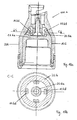
3 den Greifeinsatz der1 im Querschnitt gemäß Schnittlinie D-D aus2 , -
4 den Greifeinsatz der1 im Querschnitt gemäß Schnittlinie C-C aus2 , -
5 der Greifeinsatz der1 in perspektivischer Ansicht, -
6 einen topfförmigen, elastisch verformbaren Greifeinsatz für eine Packtulpe zum kopfseitigen Ergreifen von Flaschen in einer zweiten Ausführungsform in seitlicher Ansicht, -
7 den Greifeinsatz der6 im Längsschnitt gemäß Schnittlinie A-A aus6 , -
8 den Greifeinsatz der6 im Querschnitt gemäß Schnittlinie B-B aus7 , -
9 den Greifeinsatz der6 im Querschnitt gemäß Schnittlinie C-C aus7 , -
10 der Greifeinsatz der6 in perspektivischer Ansicht, -
11 einen topfförmigen, elastisch verformbaren Greifeinsatz für eine Packtulpe zum kopfseitigen Ergreifen von Flaschen in einer dritten Ausführungsform in seitlicher Ansicht, -
12 den Greifeinsatz der 11 im Längsschnitt gemäßSchnittlinie A-A aus 11 , -
13a, b den Greifeinsatz der 11 im Längsschnitt gemäß Schnittlinie B-B aus11 sowie die Einzelheit C aus13a in vergrößertem Maßstab, -
14 den Greifeinsatz der 11 in perspektivischer Ansicht, -
15a-d eine Packtulpe zum kopfseitigen Ergreifen von Flaschen in einer ersten Ausführungsform in Ruhestellung und in Betriebsstellung im Längsschnitt und im Querschnitt, -
16 eine Packtulpe zum kopfseitigen Ergreifen von Flaschen in einer zweiten Ausführungsform im Längsschnitt, -
17 eine Packtulpe zum kopfseitigen Ergreifen von Flaschen in einer dritten Ausführungsform im Längsschnitt und -
18a, b eine Packtulpe zum kopfseitigen Ergreifen von Flaschen in einer vierten Ausführungsform im Längsschnitt sowie im Querschnitt gemäß Schnittlinie C-C in18a .
-
1 a cup-shaped, elastically deformable gripping insert for a packing tulip for gripping bottles at the top in a first embodiment in a side view, -
2nd the gripping insert of the1 in longitudinal sectional view according to section line AA1 , -
3rd the gripping insert of the1 in cross-section according to section line DD2nd , -
4th the gripping insert of the1 in cross section according to section line CC2nd , -
5 the gripping insert of the1 in perspective view, -
6 a cup-shaped, elastically deformable gripping insert for a packing tulip for gripping bottles at the top in a second embodiment in a side view, -
7 the gripping insert of the6 in longitudinal section according to section line AA6 , -
8th the gripping insert of the6 in cross-section according to section line BB7 , -
9 the gripping insert of the6 in cross section according to section line CC7 , -
10th the gripping insert of the6 in perspective view, -
11 a cup-shaped, elastically deformable gripping insert for a packing tulip for gripping bottles at the top in a third embodiment in a side view, -
12th the gripping insert of the11 in longitudinal section according tosection line AA 11 , -
13a, b the gripping insert of the11 in longitudinal section according tosection line BB 11 as well as the detail C.13a on an enlarged scale, -
14 the gripping insert of the11 in perspective view, -
15a-d a packing tulip for gripping bottles at the top in a first embodiment in the rest position and in the operating position in longitudinal section and in cross section, -
16 a packing tulip for gripping bottles at the top in a second embodiment in longitudinal section, -
17th a packing tulip for gripping bottles at the top in a third embodiment in longitudinal section and -
18a, b a packing tulip for gripping bottles at the top in a fourth embodiment in longitudinal section and in cross section according to section line CC in18a .
In
Wesentliche erfindungsgemäße Merkmale des Greifeinsatzes
In den zwischen den im Wesentlichen axial verlaufenden Nuten
Der Schnitt D-D der
In den
In den
In der Schnittansicht B-B der
Die
Wie ferner in den Längsschnittansichten der
Was in den
Das Verhalten des Greifeinsatzes
Wie in
In
In
ZITATE ENTHALTEN IN DER BESCHREIBUNG QUOTES INCLUDE IN THE DESCRIPTION
Diese Liste der vom Anmelder aufgeführten Dokumente wurde automatisiert erzeugt und ist ausschließlich zur besseren Information des Lesers aufgenommen. Die Liste ist nicht Bestandteil der deutschen Patent- bzw. Gebrauchsmusteranmeldung. Das DPMA übernimmt keinerlei Haftung für etwaige Fehler oder Auslassungen.This list of documents listed by the applicant has been generated automatically and is only included for the better information of the reader. The list is not part of the German patent or utility model application. The DPMA assumes no liability for any errors or omissions.
Zitierte PatentliteraturPatent literature cited
- WO 2008/055893 A1 [0005]WO 2008/055893 A1 [0005]
- DE 202007001164 U1 [0005]DE 202007001164 U1 [0005]
- EP 1427637 B1 [0005]EP 1427637 B1 [0005]
- DE 202011004883 U1 [0005]DE 202011004883 U1 [0005]
- EP 3103729 [0006]EP 3103729 [0006]
Claims (21)
Applications Claiming Priority (4)
| Application Number | Priority Date | Filing Date | Title |
|---|---|---|---|
| DE102019005953.0 | 2019-08-23 | ||
| DE102019005953 | 2019-08-23 | ||
| DE102019007767 | 2019-11-10 | ||
| DE102019007767.9 | 2019-11-10 |
Publications (1)
| Publication Number | Publication Date |
|---|---|
| DE202020002201U1 true DE202020002201U1 (en) | 2020-06-17 |
Family
ID=70804495
Family Applications (1)
| Application Number | Title | Priority Date | Filing Date |
|---|---|---|---|
| DE202020002201.2U Active DE202020002201U1 (en) | 2019-08-23 | 2020-05-19 | Gripping insert for a packing tulip for gripping the head of bottles, in particular closable by a closure, packing tulip and device for gripping a bottle on the head |
Country Status (2)
| Country | Link |
|---|---|
| EP (1) | EP3782916A1 (en) |
| DE (1) | DE202020002201U1 (en) |
Citations (4)
| Publication number | Priority date | Publication date | Assignee | Title |
|---|---|---|---|---|
| EP1427637B1 (en) | 2001-09-17 | 2005-01-12 | Rudolf Zodrow | Packing tulip gripper for gripping bottles that can be sealed by a cork, crown-top, screw-top or lever stopper |
| DE202007001164U1 (en) | 2006-11-09 | 2007-04-05 | Zodrow, Rudolf | Packing tulip gripper for gripping head of bottles, has sleeve shape insert in pot shape housing whereby clamping webs have higher axial strength than clamping webs-free section |
| DE202011004883U1 (en) | 2011-04-05 | 2011-06-09 | Oberrecht, Jochen, 56651 | Packing tulip for the head-side gripping of bottles |
| EP3103729A2 (en) | 2015-06-13 | 2016-12-14 | Rudolf Zodrow | Packing tulip and method for gripping the heads of bottles |
Family Cites Families (3)
| Publication number | Priority date | Publication date | Assignee | Title |
|---|---|---|---|---|
| DE102016000174B4 (en) * | 2015-01-13 | 2022-03-17 | Rudolf Zodrow | Grip insert for a packing bell for gripping bottles and packing bells from the head |
| DE202015008614U1 (en) * | 2015-12-17 | 2016-02-04 | Rudolf Zodrow | Packing tulip for gripping in particular closable by a closure bottles |
| DE202018004841U1 (en) * | 2018-10-21 | 2019-04-18 | Rudolf Zodrow | Packing tulip for the head-side gripping of bottles |
-
2020
- 2020-05-19 DE DE202020002201.2U patent/DE202020002201U1/en active Active
- 2020-05-22 EP EP20176009.7A patent/EP3782916A1/en active Pending
Patent Citations (5)
| Publication number | Priority date | Publication date | Assignee | Title |
|---|---|---|---|---|
| EP1427637B1 (en) | 2001-09-17 | 2005-01-12 | Rudolf Zodrow | Packing tulip gripper for gripping bottles that can be sealed by a cork, crown-top, screw-top or lever stopper |
| DE202007001164U1 (en) | 2006-11-09 | 2007-04-05 | Zodrow, Rudolf | Packing tulip gripper for gripping head of bottles, has sleeve shape insert in pot shape housing whereby clamping webs have higher axial strength than clamping webs-free section |
| WO2008055893A1 (en) | 2006-11-09 | 2008-05-15 | Rudolf Zodrow | Packing tulip for gripping the top side of bottles, particularly bottles which can be sealed with a cap. |
| DE202011004883U1 (en) | 2011-04-05 | 2011-06-09 | Oberrecht, Jochen, 56651 | Packing tulip for the head-side gripping of bottles |
| EP3103729A2 (en) | 2015-06-13 | 2016-12-14 | Rudolf Zodrow | Packing tulip and method for gripping the heads of bottles |
Also Published As
| Publication number | Publication date |
|---|---|
| EP3782916A1 (en) | 2021-02-24 |
Similar Documents
| Publication | Publication Date | Title |
|---|---|---|
| EP2084067B1 (en) | Packing tulip for gripping the top side of bottles, particularly bottles which can be sealed with a cap | |
| DE102016000174B4 (en) | Grip insert for a packing bell for gripping bottles and packing bells from the head | |
| DE102009009885A1 (en) | A gripping element for gripping plastic containers | |
| DE202011004883U1 (en) | Packing tulip for the head-side gripping of bottles | |
| DE102010022869B4 (en) | Gripping insert for a packing tulip for the head-side gripping of bottles and packing tulip | |
| DE202018004841U1 (en) | Packing tulip for the head-side gripping of bottles | |
| EP3106684A1 (en) | Double nut | |
| EP3103729B1 (en) | Packing tulip and method for gripping the heads of bottles | |
| DE202020002201U1 (en) | Gripping insert for a packing tulip for gripping the head of bottles, in particular closable by a closure, packing tulip and device for gripping a bottle on the head | |
| DE102015000622A1 (en) | Gripping insert for a device for gently gripping objects | |
| EP1427637B1 (en) | Packing tulip gripper for gripping bottles that can be sealed by a cork, crown-top, screw-top or lever stopper | |
| DE102016014828B4 (en) | Packing bell for gripping bottles from the head | |
| DE102019001741B4 (en) | Packing bell for gripping bottles from the head | |
| DE112014004205B4 (en) | Dust cover | |
| EP3610988B1 (en) | Pressing device with centred bolt fixing | |
| DE10208343B4 (en) | Packing tulip for gripping the top of bottles, in particular closable by corks, crown, screw or clip closures | |
| DE102014218390B4 (en) | Gripping insert for a packing tulip for the head-side gripping of bottles and packing tulip | |
| DE10034541B4 (en) | Packer tulip for the head-side gripping of bottles | |
| DE102008024034B4 (en) | Packing tulip for the head-side gripping of bottles | |
| DE202015008614U1 (en) | Packing tulip for gripping in particular closable by a closure bottles | |
| DE202008018202U1 (en) | Packing tulip for the head-side gripping of bottles | |
| DE202016000092U1 (en) | Gripping insert for a packing tulip for grasping bottles, packing tulip and system for the head-side gripping of bottles | |
| DE202020003881U1 (en) | Gripping insert for a packing tulip and packing tulip for gripping bottles at the head | |
| DE202015106037U1 (en) | Elastic damping device and device with a component | |
| DE202006017247U1 (en) | Gripper for packing bottles comprises casing enclosing flexible sleeve with radial ribs and annular collar at its base which has no ribs and is more flexible than rest of sleeve |
Legal Events
| Date | Code | Title | Description |
|---|---|---|---|
| R207 | Utility model specification | ||
| R150 | Utility model maintained after payment of first maintenance fee after three years |