DE202016004792U1 - Reusable plug-in module board of several connectable in a plug-in module system plug-in modules with subsequently connectable LEDs, e.g. for building a LED decoration - Google Patents
Reusable plug-in module board of several connectable in a plug-in module system plug-in modules with subsequently connectable LEDs, e.g. for building a LED decoration Download PDFInfo
- Publication number
- DE202016004792U1 DE202016004792U1 DE202016004792.3U DE202016004792U DE202016004792U1 DE 202016004792 U1 DE202016004792 U1 DE 202016004792U1 DE 202016004792 U DE202016004792 U DE 202016004792U DE 202016004792 U1 DE202016004792 U1 DE 202016004792U1
- Authority
- DE
- Germany
- Prior art keywords
- plug
- housing
- connection
- modules
- module board
- Prior art date
- Legal status (The legal status is an assumption and is not a legal conclusion. Google has not performed a legal analysis and makes no representation as to the accuracy of the status listed.)
- Active
Links
- 238000005034 decoration Methods 0.000 title description 7
- 239000004020 conductor Substances 0.000 claims abstract description 3
- 230000015572 biosynthetic process Effects 0.000 claims abstract 2
- 230000013011 mating Effects 0.000 claims abstract 2
- 238000013459 approach Methods 0.000 claims description 7
- 239000011159 matrix material Substances 0.000 description 9
- 238000010276 construction Methods 0.000 description 3
- 238000005476 soldering Methods 0.000 description 2
- 238000004519 manufacturing process Methods 0.000 description 1
- 239000000463 material Substances 0.000 description 1
- 230000004048 modification Effects 0.000 description 1
- 238000012986 modification Methods 0.000 description 1
- 229920001296 polysiloxane Polymers 0.000 description 1
- 230000007704 transition Effects 0.000 description 1
Images


Classifications
-
- H—ELECTRICITY
- H01—ELECTRIC ELEMENTS
- H01R—ELECTRICALLY-CONDUCTIVE CONNECTIONS; STRUCTURAL ASSOCIATIONS OF A PLURALITY OF MUTUALLY-INSULATED ELECTRICAL CONNECTING ELEMENTS; COUPLING DEVICES; CURRENT COLLECTORS
- H01R13/00—Details of coupling devices of the kinds covered by groups H01R12/70 or H01R24/00 - H01R33/00
- H01R13/46—Bases; Cases
- H01R13/514—Bases; Cases composed as a modular blocks or assembly, i.e. composed of co-operating parts provided with contact members or holding contact members between them
-
- G—PHYSICS
- G09—EDUCATION; CRYPTOGRAPHY; DISPLAY; ADVERTISING; SEALS
- G09F—DISPLAYING; ADVERTISING; SIGNS; LABELS OR NAME-PLATES; SEALS
- G09F9/00—Indicating arrangements for variable information in which the information is built-up on a support by selection or combination of individual elements
- G09F9/30—Indicating arrangements for variable information in which the information is built-up on a support by selection or combination of individual elements in which the desired character or characters are formed by combining individual elements
- G09F9/33—Indicating arrangements for variable information in which the information is built-up on a support by selection or combination of individual elements in which the desired character or characters are formed by combining individual elements being semiconductor devices, e.g. diodes
-
- H—ELECTRICITY
- H01—ELECTRIC ELEMENTS
- H01R—ELECTRICALLY-CONDUCTIVE CONNECTIONS; STRUCTURAL ASSOCIATIONS OF A PLURALITY OF MUTUALLY-INSULATED ELECTRICAL CONNECTING ELEMENTS; COUPLING DEVICES; CURRENT COLLECTORS
- H01R13/00—Details of coupling devices of the kinds covered by groups H01R12/70 or H01R24/00 - H01R33/00
- H01R13/66—Structural association with built-in electrical component
- H01R13/6608—Structural association with built-in electrical component with built-in single component
- H01R13/6616—Structural association with built-in electrical component with built-in single component with resistor
-
- H—ELECTRICITY
- H01—ELECTRIC ELEMENTS
- H01R—ELECTRICALLY-CONDUCTIVE CONNECTIONS; STRUCTURAL ASSOCIATIONS OF A PLURALITY OF MUTUALLY-INSULATED ELECTRICAL CONNECTING ELEMENTS; COUPLING DEVICES; CURRENT COLLECTORS
- H01R13/00—Details of coupling devices of the kinds covered by groups H01R12/70 or H01R24/00 - H01R33/00
- H01R13/66—Structural association with built-in electrical component
- H01R13/717—Structural association with built-in electrical component with built-in light source
- H01R13/7175—Light emitting diodes (LEDs)
-
- H—ELECTRICITY
- H01—ELECTRIC ELEMENTS
- H01R—ELECTRICALLY-CONDUCTIVE CONNECTIONS; STRUCTURAL ASSOCIATIONS OF A PLURALITY OF MUTUALLY-INSULATED ELECTRICAL CONNECTING ELEMENTS; COUPLING DEVICES; CURRENT COLLECTORS
- H01R33/00—Coupling devices specially adapted for supporting apparatus and having one part acting as a holder providing support and electrical connection via a counterpart which is structurally associated with the apparatus, e.g. lamp holders; Separate parts thereof
- H01R33/02—Single-pole devices, e.g. holder for supporting one end of a tubular incandescent or neon lamp
-
- H—ELECTRICITY
- H01—ELECTRIC ELEMENTS
- H01R—ELECTRICALLY-CONDUCTIVE CONNECTIONS; STRUCTURAL ASSOCIATIONS OF A PLURALITY OF MUTUALLY-INSULATED ELECTRICAL CONNECTING ELEMENTS; COUPLING DEVICES; CURRENT COLLECTORS
- H01R33/00—Coupling devices specially adapted for supporting apparatus and having one part acting as a holder providing support and electrical connection via a counterpart which is structurally associated with the apparatus, e.g. lamp holders; Separate parts thereof
- H01R33/88—Coupling devices specially adapted for supporting apparatus and having one part acting as a holder providing support and electrical connection via a counterpart which is structurally associated with the apparatus, e.g. lamp holders; Separate parts thereof adapted for simultaneous co-operation with two or more identical counterparts
-
- H—ELECTRICITY
- H01—ELECTRIC ELEMENTS
- H01R—ELECTRICALLY-CONDUCTIVE CONNECTIONS; STRUCTURAL ASSOCIATIONS OF A PLURALITY OF MUTUALLY-INSULATED ELECTRICAL CONNECTING ELEMENTS; COUPLING DEVICES; CURRENT COLLECTORS
- H01R33/00—Coupling devices specially adapted for supporting apparatus and having one part acting as a holder providing support and electrical connection via a counterpart which is structurally associated with the apparatus, e.g. lamp holders; Separate parts thereof
- H01R33/92—Holders formed as intermediate parts for distributing energy in parallel through two or more counterparts at least one of which is attached to apparatus to be held
-
- H—ELECTRICITY
- H05—ELECTRIC TECHNIQUES NOT OTHERWISE PROVIDED FOR
- H05K—PRINTED CIRCUITS; CASINGS OR CONSTRUCTIONAL DETAILS OF ELECTRIC APPARATUS; MANUFACTURE OF ASSEMBLAGES OF ELECTRICAL COMPONENTS
- H05K1/00—Printed circuits
- H05K1/02—Details
- H05K1/0286—Programmable, customizable or modifiable circuits
- H05K1/029—Programmable, customizable or modifiable circuits having a programmable lay-out, i.e. adapted for choosing between a few possibilities
-
- G—PHYSICS
- G09—EDUCATION; CRYPTOGRAPHY; DISPLAY; ADVERTISING; SEALS
- G09F—DISPLAYING; ADVERTISING; SIGNS; LABELS OR NAME-PLATES; SEALS
- G09F9/00—Indicating arrangements for variable information in which the information is built-up on a support by selection or combination of individual elements
- G09F9/30—Indicating arrangements for variable information in which the information is built-up on a support by selection or combination of individual elements in which the desired character or characters are formed by combining individual elements
- G09F9/302—Indicating arrangements for variable information in which the information is built-up on a support by selection or combination of individual elements in which the desired character or characters are formed by combining individual elements characterised by the form or geometrical disposition of the individual elements
-
- H—ELECTRICITY
- H01—ELECTRIC ELEMENTS
- H01R—ELECTRICALLY-CONDUCTIVE CONNECTIONS; STRUCTURAL ASSOCIATIONS OF A PLURALITY OF MUTUALLY-INSULATED ELECTRICAL CONNECTING ELEMENTS; COUPLING DEVICES; CURRENT COLLECTORS
- H01R2103/00—Two poles
-
- H—ELECTRICITY
- H05—ELECTRIC TECHNIQUES NOT OTHERWISE PROVIDED FOR
- H05K—PRINTED CIRCUITS; CASINGS OR CONSTRUCTIONAL DETAILS OF ELECTRIC APPARATUS; MANUFACTURE OF ASSEMBLAGES OF ELECTRICAL COMPONENTS
- H05K2201/00—Indexing scheme relating to printed circuits covered by H05K1/00
- H05K2201/10—Details of components or other objects attached to or integrated in a printed circuit board
- H05K2201/10007—Types of components
- H05K2201/10106—Light emitting diode [LED]
Abstract
Steckmodulplatine bestehend aus mehreren zu dieser zusammenfügbaren Steckmodulen mit elektrischen Kontaktierungen zur Bestückung mit Leuchtdioden und/oder Spannungsanschluss, dadurch gekennzeichnet, dass die Steckmodule (10, 100) aus einzelnen block- oder würfelförmigen Anschlussgehäusen (1') bestehen, wobei die Steckmodule (10, 100) zur Bildung von seitlichen Platinenlängsreihen aus mehreren seitlich aneinander gesetzten Anschlussgehäusen (1') bestehen, welche an mindestens einer ihrer Außenseiten eine Raststruktur (11, 12; 13, 14) aus waagerecht und/oder aus senkrecht zu einander verlaufenden Längsausnehmungen (11, 12) und aus seitlich vorspringenden horizontalen und/oder vertikalen Rastrippen (13, 14) aufweisen und dass zum elektrischen Anschluss der Leuchtdioden (7) auf den Oberseiten der Anschlussgehäuse (1') zur rechten und linken Außenseite hin jeweils eine obere Führungsbohrung (3, 3') mit jeweils einer elektrischen Kontaktierung (8, 8') mit Rastvorrichtung für eines der beiden Anschlussbeine einer der anzuschließenden Leuchtdioden (7) angelegt ist, wobei die beiden Kontaktierungen desselben Anschlussgehäuses (1') einen gemeinsamen elektrischen Spannungsanschluss aufweisen zum Anschluss einer gleich großen positiven oder negativen Spannung zu beiden Außenseiten des Anschlussgehäuses (1'), und dass die elektrischen Kontaktierungen (8, 8') in angrenzenden oberen Führungsbogen (3, 3') zweier seitlich unmittelbar benachbarter, durch die Raststruktur (11, 12; 13, 14) verbundener block- oder würfelförmige Anschlussgehäuse (1') mit entgegengesetzter positiver oder negativer Polarität belegbar sind und mit einzelnen Leuchtioden (7) eine elektrische Steckverbindung (8, 8'; 7) bilden, mit welcher in Form einer Steckbrücke in die beiden Kontaktierungen (8, 8') jeweils eines der beiden Beine der Leuchtdiode (7) anschließbar ist, und dass zur Bildung einer oder mehrerer zu den Längsreihen der Steckmodul-Platine senkrechter Platinenreihen aus Steckmodulen (10, 100) auch die weiteren dort angelegten block- oder würfelförmigen Anschlussgehäuse (1') jeweils zur Kontaktierung und Steckverbindung hintereinander liegender Anschlussgehäuse (1') untereinander zur Vorderseite einen Endabschnitt (6, 6') eines überstehenden Kontaktfederstreifens (2, 2') aufweisen, wobei dieser mit den beiden Kontaktierungen (8, 8') in den oberen Führungsbohrungen (3, 3') an der Oberseite des Anschlussgehäuses (1') durch einen dorthin in diesem geführten, sich in zwei Kontaktabschnitte verzweigenden elektrisch leitenden Abschnitt verbunden ist und dass die Anschlussgehäuse (1') der Steckmodulplatine (1) ferner eine zur Gehäuserückseite sich öffnende Auslassung (15) aufweisen unter Bildung eines dortigen Rast- und Steckabschnittes (2, 6; 2', 6') in unteren Führungsbogen (3a) aus dem dort verlaufenden Abschnitt des Kontaktfederstreifens (2, 2') und dem vorstehenden Abschnitt (6, 6') des Kontaktfederstreifens (2, 2') des in einer senkrechten Reihe anzuschließenden hinteren Anschlussgehäuses, wobei die elektrisch leitend miteinander verbundenen Kontaktfederstreifen (2, 2') der senkrechten Platinenreihen jeweils einen Leiterstreifen gleicher Polarität bilden.Plug-in module board consisting of several mating to this plug-in modules with electrical contacts for assembly with light emitting diodes and / or voltage connection, characterized in that the plug-in modules (10, 100) consist of individual block or cube-shaped terminal housings (1 '), wherein the plug-in modules (10, 100) for the formation of side board longitudinal rows of a plurality of laterally juxtaposed connection housings (1 '), which on at least one of its outer sides a latching structure (11, 12, 13, 14) of horizontally and / or perpendicular to each other extending longitudinal recesses (11, 12) and from laterally projecting horizontal and / or vertical locking ribs (13, 14) and that for electrical connection of the light emitting diodes (7) on the upper sides of the connection housing (1 ') to the right and left outside each have an upper guide bore (3, 3 '), each with an electrical contact (8, 8') with locking device for a it is applied to the two connection legs of one of the light-emitting diodes (7) to be connected, the two contacts of the same connection housing (1 ') having a common electrical voltage connection for connecting an equal positive or negative voltage to both outer sides of the connection housing (1'), and the electrical contacts (8, 8 ') in adjacent upper guide arc (3, 3') of two laterally immediately adjacent, by the latching structure (11, 12; 13, 14) connected block or cube-shaped terminal housing (1 ') are assignable with opposite positive or negative polarity and with individual light emitting diodes (7) form an electrical connector (8, 8', 7), with which in the form of a jumper in the two contacts (8, 8 ') each one of the two legs of the light emitting diode (7) can be connected, and that to form one or more to the longitudinal rows of the plug-in module board vertical board rows of plug-in modules (10, 100) and the other there applied block - or cube-shaped terminal housing (1 ') respectively for contacting and plug connection one behind the other terminal housing (1') with each other to the front an end portion (6, 6 ') of a protruding contact spring strip (2, 2'), said with the two contacts (8 , 8 ') in the upper guide bores (3, 3') at the top of the connection housing (1 ') by a guided therein in this, in two contact sections branching electrically conductive portion is connected and that the connection housing (1 ') of the plug module board (1) further comprises an opening to the housing back opening (15) to form a local latching and plugging portion (2, 6; 2 ', 6') in lower guide arc (3a) from the there extending portion of the contact spring strip (2, 2 ') and the projecting portion (6, 6') of the contact spring strip (2, 2 ') to be connected in a vertical row rear Terminal housing, wherein the electrically conductive interconnected contact spring strips (2, 2 ') of the vertical rows of boards each form a conductor strip of the same polarity.
Description
In herkömmlichen Steckmodulplatinen sind die zu verwendenden Leuchtdioden (LED's) fest angeschlossen vorgegeben.In conventional plug-in modules, the LEDs to be used are permanently connected.
Die Steckmodule weisen eine große Anzahl fest angeschlossener Leuchtdioden auf. Es ist bekannt Leuchtdioden-Steckmodule in Form einer Leuchtdiodenmatrix aus einzelnen quadratischen plattenartigen Segmenten von 4,5 cm × 4,5 cm aufzubauen, welche jeweils neun Leuchtdioden aufweisen, welche mit 12 Volt bei 1,8 Watt betrieben werden. Ein Matrix-Segment erreicht bis zu 160 lm und eine Modul-Effizienz von fast 90 lm/W. Die Matrix lässt sich theoretisch nahtlos zu unendlichen Strängen, Flächen oder komplexen Formen kombinieren, ganz ohne Löten und Basteln. Die Matrix kann in vorgefertigten Segmentgrößen bestellt, aber auch von Hand nach eigenen Wünschen vergrößert und verkleinert werden. Der elektrische Anschluss der einzelnen Matrix-Segmente erfolgt für alle Leuchtdioden des Segmentes gemeinsam über einen kleinen seitlich ansetzbaren Kontaktblock mit zwei Anschlusskabeln. Es leuchten somit alle neun Leuchtdioden eines an Spannung gelegten Matrix-Segmentes gleichzeitig auf. Eine derartige Leuchtiodenmatrix wird von der Firma LUMITRONIX LED-Technik GmbH, 72379 Hechingen angeboten. Eine beliebige Form einer Leuchtdioden-Dekoration, z. B. in einer herzförmigen Kontur, ist mit diesen Matrix-Segmenten aber nicht möglich.The plug-in modules have a large number of permanently connected LEDs. It is known to build light emitting diode plug-in modules in the form of a light-emitting diode matrix of individual square plate-like segments of 4.5 cm × 4.5 cm, each having nine light-emitting diodes, which are operated with 12 volts at 1.8 watts. A matrix segment reaches up to 160 lm and a module efficiency of almost 90 lm / W. The matrix can theoretically be seamlessly combined into infinite strands, surfaces or complex shapes, without soldering or tinkering. The matrix can be ordered in prefabricated segment sizes, but can also be enlarged and reduced by hand according to your own wishes. The electrical connection of the individual matrix segments is carried out for all light emitting diodes of the segment together via a small laterally attachable contact block with two connecting cables. Thus, all nine light-emitting diodes of a voltage-applied matrix segment light up simultaneously. Such a light-emitting diode matrix is offered by LUMITRONIX LED-Technik GmbH, 72379 Hechingen. Any form of light-emitting diode decoration, z. B. in a heart-shaped contour, but is not possible with these matrix segments.
Bei herkömmlichen einfachen Platinen müssen die einzelnen Leuchtdioden entsprechend der gewünschten Form der Lichterkette auf rasterförmig über die Platinenoberfläche fabrikmäßig verteilt vorgesehenen Anschlusspunkte angelötet werden. Die Verbindung entsprechender elektrischer Anschlüsse erfolgt auf den einzelnen Platinen durch anzulötende Anschlusskabel.In conventional simple circuit boards, the individual light-emitting diodes must be soldered in accordance with the desired shape of the light string on raster-shaped over the board surface distributed factory provided connection points. The connection of corresponding electrical connections is made on the individual boards by connecting cable to be soldered.
Die Erstellung komplexer, insbesondere dreidimensionaler Formen ist insofern nicht möglich. Des weiteren ist die Erstellung einer Leuchtdioden-Dekoration, z. B. in herzförmiger Kontur, äußerst aufwendig.The creation of complex, in particular three-dimensional shapes is not possible in this respect. Furthermore, the creation of a light-emitting diode decoration, z. B. in heart-shaped contour, extremely expensive.
Das erfindungsgemäße Steckmodulsystem soll ohne Löten den Aufbau unterschiedlicher Arten von LED Dekorationen aus Steckmodulen ermöglichen und dies auch in unterschiedlicher Größe und Form des Steckmodulsystems bzw. der Steckmodule der Steckmodulplatine in ein-, zwei- und dreidimensionaler Weise. Ausgehend von bekannten Steckmodulplatinen bestehend aus mehreren zu dieser zusammenfügbaren segmentartigen Steckmodulen mit elektrischer Kontaktierung zur Bestückung und zum Spannungsanschluss der Leuchtdioden auf der Platinenoberfläche ist neuerungsgemäß eine Ausbildung der Steckmodule gemäß Anspruch 1 vorgesehen. Die Leichtdioden können somit mit ihren Diodenbeinen auf als Rast- und Steckvorrichtung ausgebildeten Kontaktierungen einzeln aufgesteckt und durch einen gemeinsamen positiven oder negativen elektrischen Anschluss der in senkrechten Reihen verbundenen Steckmodule mit Spannung versorgt werden.The plug-in module system according to the invention is intended to allow the construction of different types of LED decorations from plug-in modules without soldering and this in different size and shape of the plug-in module system or the plug-in modules of the plug-in module board in one, two and three-dimensional manner. Starting from known plug-in module boards consisting of a plurality of this segmentable plug-in modules with electrical contacting for assembly and voltage connection of the light emitting diodes on the board surface according to the invention an embodiment of the plug-in modules according to
Vorteilhafte Ausführungen der Neuerung ergeben sich aus den Ansprüchen 1–9.Advantageous embodiments of the innovation will become apparent from the claims 1-9.
In den Zeichnungen sind vorteilhafte Ausführungsformen der Neuerung in
In den Zeichnungen zeigen:In the drawings show:
Für die Anschlussgehäuse (
Aufbauconstruction
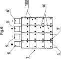
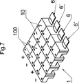
Die Steckmodule (
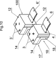
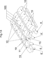
Die beiden oberen Enden (
Die beiden rechten und linken Außenseiten des Anschlussgehäuses (
Eine runde, konkave und konvexe Struktur der beiden Außenseiten des Anschlussgehäuses (
Die Steckmodule (
Dabei erfolgt eine Übersteckung des am unteren Ende der Kontaktfederstreifen (
Beispiel:Example:
Eine Herzdekoration mit aufgesteckten Leuchtdioden gemäß
BezugszeichenlisteLIST OF REFERENCE NUMBERS
- 11
- SteckmodulplatinePlug-in module board
- 1'1'
- Anschlussgehäuseconnection housing
- 2, 2'2, 2 '
- Kontaktfederstreifen zweier benachbarter SteckmoduleContact spring strips of two adjacent plug-in modules
- 33
- Zwei benachbarte obere rechte bzw. linke Führungsbohrungen zur Oberseite des Anschlussgehäuses verlaufend zur Aufnahme der Kontaktierung eines ersten Diodenbeins (Pluspol) einer LeuchtdiodeTwo adjacent upper right and left guide holes to the top of the terminal housing extending for receiving the contacting of a first diode leg (positive pole) of a light emitting diode
- 3'3 '
- Zwei benachbarte obere rechte und linke Führungsbohrungen (Löcher) zur Oberseite eines zum linken Anschlussgehäuses benachbarten rechten Anschlussgehäuses verlaufend zur Anlage der Kontaktierung eines zweiten Diodenbeins (Minuspol) der Leuchtdiode im benachbarten SteckmodulTwo adjacent upper right and left guide holes (holes) to the top of a right terminal housing adjacent to the left terminal housing extending to make contact with a second diode leg (negative terminal) of the LED in the adjacent plug-in module
- 3a3a
- Untere FührungsbohrungLower guide bore
- 44
- Breite Öffnung der Führungsbohrung für den Kontaktfederstreifen auf der vorderen Stirnseite des Gehäuses sich öffnendWide opening of the guide hole for the contact spring strip on the front end of the housing opening
- 55
-
Zwei obere Kontaktierungen des Kontaktfederstreifens eines Steckmoduls am oberen Ende der in dessen linke oder rechte obere Führungsbohrung (
3 ) ragenden abgebogenen Abschnitte des Kontaktfederstreifens für die Verbindung und zum elektrischen Anschluss jeweils einer der beiden Diodenbeine einer Leuchtdiode in der oberen rechten und linken Führungsbohrung (3 ,3' ) jeweils eines zweier angrenzender Steckmodule in Art einer übergreifenden SteckbrückeTwo upper contacts of the contact spring strip of a plug-in module at the upper end in the left or right upper guide bore (3 ) projecting bent portions of the contact spring strip for the connection and the electrical connection in each case one of the two diode legs of a light-emitting diode in the upper right and left guide bore (3 .3 ' ) Each one of two adjacent plug-in modules in the manner of a cross-link jumper - 66
-
Vorderer unterer gemeinsamer Endabschnitt der in die beiden linken oberen Führungsbohrungen (
3 ) ragenden Kontaktabschnitte des Kontaktfederstreifens (2 )Front lower common end portion of the in the two upper left guide holes (3 ) projecting contact portions of the contact spring strip (2 ) - 6'6 '
-
Vorderer unterer gemeinsamer Endabschnitt der in die beiden rechten oberen Führungsbohrungen (
3' ) ragenden Kontaktabschnitte des Kontaktfederstreifens (2' )Front lower common end portion of the in the two upper right guide holes (3 ' ) projecting contact portions of the contact spring strip (2 ' ) - 2, 6; 2', 6'2, 6; 2 ', 6'
- Rast- und SteckabschnittLatching and plug-in section
- 77
-
Leuchtdioden mit Diodenbeinen, welche über die Kontaktfederstreifen zweier benachbarter Gehäuse im oberen Bereich der Führungsbohrungen (
3 ,3' ) einsteckbar sindLight emitting diodes with diode legs, which via the contact spring strips of two adjacent housing in the upper region of the guide holes (3 .3 ' ) are plugged - 8, 8'8, 8 '
-
Zwei Kontaktierungen des Kontaktfederstreifens für die Verbindung jeweils einer der Diodenbeine einer Leuchtdiode in der oberen rechten und linken Führungsbohrung (
3 ) des jeweiligen Steckmoduls durch eine übergreifende SteckbrückeTwo contacts of the contact spring strip for connecting in each case one of the diode legs of a light-emitting diode in the upper right and left guide bore (FIG.3 ) of the respective plug-in module by an overarching jumper - 99
-
Abbiegung der Enden (
5 ,6 ) des Kontaktfederstreifens (2 ) zur Erzeugung des Stecksystems (8 )Turning the ends (5 .6 ) of the contact spring strip (2 ) for the production of the plug-in system (8th ) - 1010
- Steckmodule gleicher Polarität, positivPlug-in modules of the same polarity, positive
- 100100
- Seitliche Steckmodule dazu, gleiche Polarität, negativSide plug-in modules, same polarity, negative
- 1111
-
Raststruktur zur Verbindung seitlich benachbarter Steckmodule aus konkaver horizontaler Längsausnehmung an der rechten Außenseite des Gehäuses (
1 )Detent structure for connecting laterally adjacent plug-in modules of concave horizontal longitudinal recess on the right outer side of the housing (1 ) - 1212
-
Raststruktur zur Verbindung seitlich benachbarter Steckmodule aus konkaver vertikaler Längsausnehmung an der rechten Außenseite des Gehäuses (
1 )Detent structure for connecting laterally adjacent plug-in modules of concave vertical longitudinal recess on the right outer side of the housing (1 ) - 1313
-
Seitlich vorspringende horizontaler Rastrippen an der linken Außenseite des Gehäuses (
1 ) zur Führung in der äußeren seitlichen horizontalen Längsausnehmung eines benachbarten GehäusesLaterally projecting horizontal locking ribs on the left outside of the housing (1 ) for guiding in the outer lateral horizontal longitudinal recess of an adjacent housing - 1414
-
Seitlich vorspringende vertikale Rastrippen an der linken Außenseite des Gehäuses (
1 ) zur Führung in der äußeren seitlichen vertikalen Längsausnehmung eines benachbarten GehäusesLaterally projecting vertical locking ribs on the left outside of the housing (1 ) for guiding in the outer lateral vertical longitudinal recess of an adjacent housing - 1515
-
Auslassung mit innerer unterer Öffnung der unteren Führungsbohrung (
3a ) mit Steckaufnahmen für den vorderen Rast- und Steckabschnitt des Kontaktfederstreifens des in gleicher Längsrichtung dort zu übersteckenden weiteren hinteren Steckmoduls (10 ) gleicher PolaritätOmission with inner lower opening of the lower guide hole (3a ) with plug-in receptacles for the front latching and plug-in section of the contact spring strip of the further rear plug-in module to be plugged over there in the same longitudinal direction (10 ) of the same polarity - 1616
- Oberseite der Platine bzw. des Layouts der Steckmodule für den Aufbau der LED-Dekoration mit positiven und negativen Kontaktierungsleitungen für die Spannung der Kontaktfederstreifen bzw. der jeweils beiden Diodenbeine der Leuchtdioden, welche auf den Oberseiten zweier benachbarter Steckmodule in Form von Brücken eingesteckt sind.Top of the board or the layout of the plug-in modules for the construction of the LED decoration with positive and negative Kontaktierungsleitungen for the voltage of the contact spring strips or the respective two diode legs of the light-emitting diodes, which are plugged into the tops of two adjacent plug-in modules in the form of bridges.
- 1717
- hinterer oberer Gehäuseansatzrear upper housing approach
- 1818
- vorderer, zum hinteren obereren Gehäuseansatz tiefer verlaufender Gehäuseansatzfront, to the rear upper housing approach deeper running housing approach
- 1919
- Verbindungsstangenconnecting rods
- 2020
- Längsrippelongitudinal rib
- 2121
- Längsausnehmunglongitudinal recess
Claims (9)
Priority Applications (7)
| Application Number | Priority Date | Filing Date | Title |
|---|---|---|---|
| DE202016004792.3U DE202016004792U1 (en) | 2016-08-04 | 2016-08-04 | Reusable plug-in module board of several connectable in a plug-in module system plug-in modules with subsequently connectable LEDs, e.g. for building a LED decoration |
| DE102017005223.9A DE102017005223A1 (en) | 2016-08-04 | 2017-06-01 | Reusable plug-in module board comprising a plurality of plug-in modules which can be connected in a plug-in module system with subsequently connectable light emitting diodes, e.g. for building a LED decoration |
| CN201780048998.4A CN109601020B (en) | 2016-08-04 | 2017-08-01 | Plug-in module circuit board capable of being used repeatedly |
| PCT/DE2017/000241 WO2018024273A1 (en) | 2016-08-04 | 2017-08-01 | Reusable plug-in module circuit board comprising a plurality of plug-in modules which can be connected in a plug-in module system and have light-emitting diodes which can be retrofitted for example for constructing a decorative led arrangement |
| US16/317,882 US10498069B2 (en) | 2016-08-04 | 2017-08-01 | Plug-in modules and plug-in module systems |
| EP17754601.7A EP3494569B1 (en) | 2016-08-04 | 2017-08-01 | Reusable plug-in module circuit board comprising a plurality of plug-in modules which can be connected in a plug-in module system and have light-emitting diodes which can be retrofitted for example for constructing a decorative led arrangement |
| KR1020197006202A KR102213791B1 (en) | 2016-08-04 | 2017-08-01 | Reusable plug-in module board with subsequent connection of light-emitting diodes, consisting of a number of plug-in modules that can be connected to a plug-in module system, for example for making LED decorations. |
Applications Claiming Priority (1)
| Application Number | Priority Date | Filing Date | Title |
|---|---|---|---|
| DE202016004792.3U DE202016004792U1 (en) | 2016-08-04 | 2016-08-04 | Reusable plug-in module board of several connectable in a plug-in module system plug-in modules with subsequently connectable LEDs, e.g. for building a LED decoration |
Publications (1)
| Publication Number | Publication Date |
|---|---|
| DE202016004792U1 true DE202016004792U1 (en) | 2016-08-29 |
Family
ID=56937202
Family Applications (2)
| Application Number | Title | Priority Date | Filing Date |
|---|---|---|---|
| DE202016004792.3U Active DE202016004792U1 (en) | 2016-08-04 | 2016-08-04 | Reusable plug-in module board of several connectable in a plug-in module system plug-in modules with subsequently connectable LEDs, e.g. for building a LED decoration |
| DE102017005223.9A Withdrawn DE102017005223A1 (en) | 2016-08-04 | 2017-06-01 | Reusable plug-in module board comprising a plurality of plug-in modules which can be connected in a plug-in module system with subsequently connectable light emitting diodes, e.g. for building a LED decoration |
Family Applications After (1)
| Application Number | Title | Priority Date | Filing Date |
|---|---|---|---|
| DE102017005223.9A Withdrawn DE102017005223A1 (en) | 2016-08-04 | 2017-06-01 | Reusable plug-in module board comprising a plurality of plug-in modules which can be connected in a plug-in module system with subsequently connectable light emitting diodes, e.g. for building a LED decoration |
Country Status (6)
| Country | Link |
|---|---|
| US (1) | US10498069B2 (en) |
| EP (1) | EP3494569B1 (en) |
| KR (1) | KR102213791B1 (en) |
| CN (1) | CN109601020B (en) |
| DE (2) | DE202016004792U1 (en) |
| WO (1) | WO2018024273A1 (en) |
Families Citing this family (6)
| Publication number | Priority date | Publication date | Assignee | Title |
|---|---|---|---|---|
| US8587950B2 (en) | 2011-05-31 | 2013-11-19 | Server Technology, Inc. | Method and apparatus for multiple input power distribution to adjacent outputs |
| US10249998B2 (en) | 2017-07-13 | 2019-04-02 | Server Technology, Inc. | Combination outlet and power distribution unit incorporating the same |
| CN110792408A (en) | 2019-11-13 | 2020-02-14 | 百勤能源科技(惠州)有限公司 | Hard-sealing soluble bridge plug |
| US11196212B2 (en) | 2020-03-16 | 2021-12-07 | Server Technology, Inc. | Locking combination outlet module and power distribution unit incorporating the same |
| TWI739689B (en) * | 2020-12-07 | 2021-09-11 | 佳必琪國際股份有限公司 | Connector fixing structure |
| US11469534B1 (en) * | 2021-06-11 | 2022-10-11 | Jace Cole | Junction box |
Family Cites Families (13)
| Publication number | Priority date | Publication date | Assignee | Title |
|---|---|---|---|---|
| US6386733B1 (en) * | 1998-11-17 | 2002-05-14 | Ichikoh Industries, Ltd. | Light emitting diode mounting structure |
| DE10392736T5 (en) * | 2002-10-25 | 2005-07-07 | Moriyama Sangyo K.K. | light module |
| JP4548219B2 (en) | 2005-05-25 | 2010-09-22 | パナソニック電工株式会社 | Socket for electronic parts |
| CN102114352B (en) * | 2010-12-31 | 2013-11-06 | 东莞和佳塑胶制品有限公司 | Luminous building block with power connection structure and power supply seat thereof |
| CN202289484U (en) * | 2011-10-10 | 2012-07-04 | 东莞和佳塑胶制品有限公司 | Luminous building block with power connection structures and power connection structures of luminous building block |
| US20130163234A1 (en) * | 2011-12-21 | 2013-06-27 | Chuang Tzu Hsien | Block led light |
| CN203120097U (en) * | 2013-01-25 | 2013-08-07 | 赵浩波 | Sound box and combination type sound box composed of the sound boxes |
| US9374909B2 (en) * | 2013-03-14 | 2016-06-21 | Bardwell & Mcalister Inc. | Method of manufacturing LED module |
| EP2818219A1 (en) * | 2013-06-28 | 2014-12-31 | Chia-Yen Lin | Modularized contact type of conductive building block |
| CN104248854B (en) * | 2013-06-28 | 2016-08-17 | 龙门县佳茂聚氨酯橡胶有限公司 | The electrical connection building blocks of contact conduction and power connection mechanism thereof |
| CN203384710U (en) * | 2013-07-09 | 2014-01-08 | 六景光电科技有限公司 | Combined type LED (light-emitting diode) lamp |
| CN104984552B (en) * | 2013-09-03 | 2017-10-31 | 深圳市翰童科技有限公司 | A kind of splice |
| CN103495284B (en) * | 2013-10-17 | 2016-08-10 | 深圳市翰童科技有限公司 | Multi-surface contact electronic toy brick |
-
2016
- 2016-08-04 DE DE202016004792.3U patent/DE202016004792U1/en active Active
-
2017
- 2017-06-01 DE DE102017005223.9A patent/DE102017005223A1/en not_active Withdrawn
- 2017-08-01 US US16/317,882 patent/US10498069B2/en active Active
- 2017-08-01 WO PCT/DE2017/000241 patent/WO2018024273A1/en unknown
- 2017-08-01 CN CN201780048998.4A patent/CN109601020B/en active Active
- 2017-08-01 KR KR1020197006202A patent/KR102213791B1/en active IP Right Grant
- 2017-08-01 EP EP17754601.7A patent/EP3494569B1/en active Active
Also Published As
| Publication number | Publication date |
|---|---|
| CN109601020A (en) | 2019-04-09 |
| US20190252819A1 (en) | 2019-08-15 |
| US10498069B2 (en) | 2019-12-03 |
| EP3494569A1 (en) | 2019-06-12 |
| CN109601020B (en) | 2021-08-10 |
| WO2018024273A1 (en) | 2018-02-08 |
| KR102213791B1 (en) | 2021-02-08 |
| EP3494569B1 (en) | 2020-11-04 |
| DE102017005223A1 (en) | 2018-02-08 |
| KR20190035837A (en) | 2019-04-03 |
Similar Documents
| Publication | Publication Date | Title |
|---|---|---|
| DE202016004792U1 (en) | Reusable plug-in module board of several connectable in a plug-in module system plug-in modules with subsequently connectable LEDs, e.g. for building a LED decoration | |
| DE102017220054B4 (en) | Electrical connector for printed circuit boards and manufacturing method thereof | |
| DE102008034956A1 (en) | Connecting element for connecting surface mount device type LED-strips, has two contact elements provided in interior of receptacle elements and contacting strip shaped printed circuit boards in multiple poles | |
| DE102010038251A1 (en) | OLED illuminant for a luminaire | |
| EP1780837B1 (en) | Electrical connection arrangement for a circuit board | |
| DE102004054203A1 (en) | Insulation displacement-plug-in contact strip for electrical plug-in connector, has connecting units arranged in multiple rows such that insulation displacement connectors of units lie in strip for placing plug-in contacts of units in row | |
| DE102018111733A1 (en) | PCB connector | |
| DE102005009856A1 (en) | Connection or device adapter | |
| DE102004004777A1 (en) | Deformable lighting module | |
| DE202013005015U1 (en) | Solar module with combined mechanical and electrical connector for generating electricity | |
| DE102011114936B4 (en) | Electronic module and contact element for this purpose | |
| EP2667454B1 (en) | Variable plug connector | |
| WO2015144676A1 (en) | Electronics housing having an electrical circuit arrangement | |
| EP2948712B1 (en) | Illuminant | |
| DE202015105021U1 (en) | Connection housing with a connecting device for conductors | |
| DE102017124594A1 (en) | Device for electrical contacting | |
| DE102014115384A1 (en) | Test cable and socket adapter for a test cable | |
| EP3413400B1 (en) | Transverse connector comb | |
| DE10351479A1 (en) | Implement system with electric/electronic appliances and bus line mounted on support rail, e.g. hat-shaped rail for their interconnection, or link to external supply, control and display apparatus | |
| DE102009003533B4 (en) | Cross connector for terminal blocks | |
| DE2116342A1 (en) | Electrical connectors | |
| DE202005015465U1 (en) | Plug connector system, has contact carrier including female or male interfaces at their ends, where carriers of female and male plug connectors are identically formed independent of connection methods of plug connections | |
| DE202016103909U1 (en) | connector system | |
| DE102011102406A1 (en) | Lamp e.g. street lamp mounted in residential area, has LED whose connection pins are plugged into base element so that central region of irradiation axis of LED is set at specific angle with respect to board | |
| DE102012015037A1 (en) | electronic module |
Legal Events
| Date | Code | Title | Description |
|---|---|---|---|
| R086 | Non-binding declaration of licensing interest | ||
| R207 | Utility model specification | ||
| R021 | Search request validly filed | ||
| R163 | Identified publications notified | ||
| R150 | Utility model maintained after payment of first maintenance fee after three years | ||
| R151 | Utility model maintained after payment of second maintenance fee after six years |