Die Erfindung betrifft Vorrichtung zur automatisierten Vereinzelung von nicht-magazinierten Profilen. In einer bevorzugten Ausführungsform der Erfindung wird dies durch eine Vorrichtung realisiert, die unter anderem Schnittkanten der Profile derart beleuchtet, dass die Schnittkanten relativ hell gegenüber den verbleibenden Abschnitten der Profile erscheinen, wird die Position derjenigen Schnittkante des Profils mit der höchsten Höhenkomponente in einem Teilbereich eines aufgenommen Bildes bestimmt, und mittels eines Greifers eines Roboters die bestimmte Position angefahren und das entsprechende Profil vereinzelt.The invention relates to a device for automated separation of non-magazine profiles. In a preferred embodiment of the invention, this is realized by a device which illuminates, inter alia, cut edges of the profiles such that the cut edges appear relatively bright with respect to the remaining sections of the profiles, the position of that cut edge of the profile with the highest height component in a portion of a Picture determined, and approached by means of a gripper of a robot, the specific position and the corresponding profile isolated.
Stand der TechnikState of the art
Herkömmlicherweise werden Kunststoffprofile manuell aus einem Transportbehälter entnommen und einer Konfektionieranlage zugeführt. Die Transportbehälter stehen auf einer Hubeinheit und werden beim Entladen angehoben, so dass der Mitarbeiter bei der Entnahme der Profile aus dem Behälter rückenschonend arbeiten kann. Die Hubeinheit wird dabei von dem Mitarbeiter bedient. Kleine Profile werden in ein Magazin, welches sich vor dem Einzug der Konfektionieranlage befindet, eingesteckt, während große Profile direkt in die Konfektionieranlage eingeschoben werden.Conventionally, plastic profiles are manually removed from a transport container and fed to a confectioning system. The transport containers stand on a lifting unit and are lifted during unloading, so that the employee can work back-friendly when removing the profiles from the container. The lifting unit is operated by the employee. Small profiles are plugged into a magazine, which is located in front of the feeder unit, while large profiles are inserted directly into the assembly line.
Bei den Profilen wird zwischen Hohlprofilen und Flachprofilen unterschieden. Ein Hohlprofil weist mindestens eine Hohlkammer auf, wie in 1 dargestellt. Flachprofile hingegen weisen keine Hohlkammer auf, wie ebenfalls in 1 gezeigt.The profiles distinguish between hollow profiles and flat profiles. A hollow profile has at least one hollow chamber, as in 1 shown. Flat profiles, however, have no hollow chamber, as also in 1 shown.
Die Druckschrift AT 500 778 B1 offenbart eine Vorrichtung zum Konfektionieren von steifen, einseitig offenen Behältern, wie z. B. Tüten oder Becher, durch Einsetzen in an ihre Außenkontur angepasste, formstabile Konfektionierhüllen. Die Behälter werden von einer mehrere nebeneinanderliegende Transportbahnen aufweisenden Transportvorrichtung unter einer Abgabevorrichtung hindurchtransportiert, die die Konfektionierhüllen in den Transportbahnen ablegt. Die Abgabevorrichtung umfasst eine mit schräg nach unten verlaufenden Ablagerinnen für stangenförmige Konfektionierhüllenstapel versehene Ablage, eine der Ablage nachgeordnete Haltevorrichtung für die Konfektionierhüllenstapel und eine Übergabevorrichtung mit einem mit Saugköpfen versehenen, oberhalb der Transportbahnen hin und her bewegbaren Schlitten, der die Konfektionierhüllen mit seinen Saugköpfen von den Konfektionierhüllenstapeln abzieht und in den Transportbahnen ablegt.The publication AT 500 778 B1 discloses an apparatus for assembling rigid, unilaterally open containers, such. As bags or cups, by inserting adapted to their outer contour, dimensionally stable confection packaging. The containers are transported by a transport device having a plurality of juxtaposed transport paths under a dispensing device, which stores the confectioning cases in the transport paths. The dispensing device comprises a shelf provided with obliquely downwards Ablagerinnen for rod-shaped confectioning case stack, a storage subordinate holding device for the confectioning case stack and a transfer device with a suction cups, above the transport paths reciprocally movable carriage, the confectioning cases with its suction from the Pull off the stacking sleeves and place them in the transport lanes.
Der vorgenannte Stand der Technik sieht jedoch vor, die Behälter, wie Tüten oder Becher, magaziniert in eigens maßgeschneiderten Transportbahnen bereitzustellen.However, the aforementioned prior art provides for the containers, such as bags or cups, to be stored in specially tailored transport paths in magazine form.
Die Druckschrift DE 10 2005 011 330 A1 offenbart ein Verfahren zur Lageerkennung eines insbesondere nicht rotationssymmetrischen Formteils aus beispielsweise keramischem oder metallischem Material, bei dem mittels einer Lichtquelle das Formteil punkt- oder linienförmig unter einem ersten Winkel angeleuchtet wird und mittels einer Kamera ein Kamerabild unter einem dazu verschiedenen Winkel aufgenommen wird zum Bereitstellen eines dreidimensionalen Abbildes des Formteils, eine Kontur innerhalb des Formteils erfasst wird und mittels der Kontur auf die Lage des Formteils geschlossen wird, wobei vor oder bei dem Konturerfassen Datenanteile nicht relevanter Daten des Kamerabildes durch deren Ausblenden reduziert werden.The publication DE 10 2005 011 330 A1 discloses a method for detecting the position of a particular non-rotationally symmetrical molded part of, for example, ceramic or metallic material, in which by means of a light source, the molded part is punctiform or linear illuminated at a first angle and a camera image is taken at a different angle for providing a camera by means of a camera Three-dimensional image of the molded part, a contour is detected within the molding and closed by means of the contour on the position of the molding, wherein prior to or at the Contourfassen data portions of non-relevant data of the camera image are reduced by hiding.
Dieser Stand der Technik lehrt eine extreme Form der Magazinierung, nämlich eine Einzelzuführung der Formteile per Förderband.This prior art teaches an extreme form of magazining, namely a single feed of the molded parts by conveyor belt.
Darstellung der Erfindung: Aufgabe, Lösung, VorteileDESCRIPTION OF THE INVENTION: Problem, Solution, Advantages
Die vorstehend beschriebenen Stände der Technik realisieren lediglich eine konventionelle Zuführung verschiedener Objekte zu einer Konfektionieranlage. Es bleibt jedoch das Potenzial unberücksichtigt, das eine Zuführung nicht-magazinierter Objekte bzw. Profile bietet, und demzufolge wird auch keine Lösung zur Vereinzelung solcher nicht-magazinierter Objekte bzw. Profile bereitgestellt.The state of the art described above realize only a conventional supply of various objects to a confectioning plant. However, it does not take account of the potential offered by feeding non-magazined objects or profiles, and consequently no solution is provided for singulating such non-magazated objects or profiles.
Daher liegt der Erfindung die Aufgabe zugrunde, das vorstehend beschriebene Problem zu lösen.Therefore, the invention has the object to solve the problem described above.
Die erfindungsgemäße Lösung sieht in einem ersten Aspekt eine Vorrichtung zur automatisierten Vereinzelung von nicht-magazinierten Profilen aus einem Transportbehälter vor, wobei Schnittkanten der Profile im Wesentlichen bündig bezüglich des Transportbehälters überstehen, umfassend ein Beleuchtungssystem, das eingerichtet ist, um die Schnittkanten der Profile derart zu beleuchten, dass die Schnittkanten relativ hell gegenüber den verbleibenden Abschnitten der Profile erscheinen, ein Bilderkennungssystem mit einer Kamera, das eigerichtet ist, um ein Bild zumindest eines Teilbereichs der Schnittkanten aufzunehmen, die Schnittkanten basierend auf einem Kantenmodell aus dem Bild zu erkennen, Positionen der Schnittkanten mit einer Breitenkomponente und einer Höhenkomponente zu ermitteln, und die Position derjenigen Schnittkante des Profils mit der höchsten Höhenkomponente in dem Teilbereich zu bestimmen, und einen Roboter mit einem Greifer, wobei der Roboter eingerichtet ist, um mittels des Greifers die bestimmte Position anzufahren und das entsprechende Profil zu vereinzeln.The solution according to the invention provides, in a first aspect, an apparatus for automated separation of non-magazineed profiles from a transport container, wherein cut edges of the profiles substantially flush with respect to the transport container, comprising a lighting system which is adapted to the cut edges of the profiles so highlight that the cut edges appear relatively bright with respect to the remaining portions of the profiles, an image recognition system having one A camera adapted to capture an image of at least a portion of the cut edges, detect the cut edges from the image based on an edge model, determine positions of the cut edges with a width component and a height component, and the position of that cut edge of the profile with the highest Determine height component in the sub-area, and a robot with a gripper, wherein the robot is arranged to move by means of the gripper to the specific position and to separate the corresponding profile.
In einer ersten Ausgestaltung des ersten Aspekts ist die Position vorzugsweise der Schnittkante ein Referenzpunkt, der durch das Kantenmodell vorgegeben wird. In diesem Fall fällt vorzugsweise der Referenzpunkt mit einem Schwerpunkt der Schnittkante zusammen.In a first embodiment of the first aspect, the position of the cut edge is preferably a reference point which is predetermined by the edge model. In this case, preferably the reference point coincides with a center of gravity of the cutting edge.
In einer zweiten Ausgestaltung des ersten Aspekts ist vorzugsweise das Bilderkennungssystem eingerichtet, um Schnittkanten, die lediglich teilweise in dem Teilbereich liegen, von der Positionsbestimmung auszuschließen. Alternativ oder zusätzlich ist vorzugsweise das Bilderkennungssystem eingerichtet, um Schnittkanten, die zur Gänze in einem Randbereich des Teilbereichs liegen, von der Positionsbestimmung auszuschließen. Alternativ oder zusätzlich ist vorzugsweise das Bilderkennungssystem eingerichtet, um eine bestimmte Position zu verwerfen, wenn eine potenzielle Kollision mit einem anderen Profil erkannt wird. In letzterem Fall ist vorzugsweise das Bilderkennungssystem eingerichtet, um eine potenzielle Kollision durch Abgleich der Höhenkomponente der bestimmten Position mit der Höhenkomponente einer Position des potenziell kollidierenden Profils zu bestimmen. Alternativ oder zusätzlich ist vorzugsweise das Bilderkennungssystem eingerichtet, um zusätzlich einen Winkel zwischen einer Hauptachse der Schnittkanten und der Breitenachse des Teilbereichs zu bestimmen, und Schnittkanten, deren Winkel einen vorbestimmten Winkel überschreitet, von der Positionsbestimmung auszuschließen.In a second embodiment of the first aspect, the image recognition system is preferably set up in order to exclude cutting edges that lie only partially in the subarea from the position determination. As an alternative or in addition, the image recognition system is preferably set up in order to exclude from the position determination cut edges which lie entirely in an edge region of the partial region. Alternatively or additionally, the image recognition system is preferably set up to discard a specific position when a potential collision with another profile is detected. In the latter case, preferably, the image recognition system is arranged to determine a potential collision by matching the height component of the particular position with the height component of a position of the potentially colliding profile. Alternatively or additionally, the image recognition system is preferably set up in order additionally to determine an angle between a main axis of the cut edges and the width axis of the subarea, and to exclude cut edges whose angle exceeds a predetermined angle from the position determination.
In einer dritten Ausgestaltung des ersten Aspekts ist vorzugsweise der Teilbereich eine Breitenteilung der Schnittkanten in dem Transportbehälter. In diesem Fall schließt vorzugsweise der Teilbereich die obere Lage der Schnittkanten ein. Wenn dem so ist, dann ist vorzugsweise das Bilderkennungssystem eingerichtet, um den Teilbereich um eine Breitenteilung weiter zu verschieben, wenn die Vereinzelung dazu führte, das der Teilbereich nicht mehr die obere Lage der Schnittkanten einschließt.In a third embodiment of the first aspect, the subregion is preferably a width division of the cut edges in the transport container. In this case, the partial area preferably includes the upper layer of the cut edges. If so, then the image recognition system is preferably set up in order to shift the partial area further by a width division, if the separation led to the partial area no longer enclosing the upper position of the cut edges.
In einer vierten Ausgestaltung des ersten Aspekts ist vorzugsweise das Bilderkennungssystem eingerichtet, um die aufgenommen Schnittkanten mit einer Mehrzahl von zuvor gespeicherten verschiedenen Kantenmodellen abzugleichen. In diesem Fall ist vorzugsweise jedes der verschiedenen Kantenmodelle in verschiedenen Orientierungen gespeichert. Wenn dem so ist, dann ist vorzugsweise jedes der verschiedenen Kantenmodelle als ein Urbild und zumindest eine Spiegelung des Urbilds gespeichert.In a fourth embodiment of the first aspect, the image recognition system is preferably set up to match the recorded cut edges with a plurality of previously stored different edge models. In this case, preferably, each of the different edge models is stored in different orientations. If so, then preferably each of the different edge models is stored as a template and at least one mirror of the template.
In einer fünften Ausgestaltung des ersten Aspekts ist vorzugsweise das Beleuchtungssystem eingerichtet, um Licht im blauen Wellenlängenbereich auszusenden. In diesem Fall weist vorzugsweise die Kamera weiterhin ein Bandpassfilter auf, das eingerichtet ist, um Licht außerhalb des blauen Wellenlängenbereichs auszufiltern. Alternativ oder zusätzlich ist vorzugsweise das Beleuchtungssystem als eine Ringbeleuchtung ausgestaltet. Außerdem ist verläuft vorzugsweise die optische Achse der Kamera im Wesentlichen lotrecht zu einer Ebene, die die Schnittkanten in dem Teilbereich enthält.In a fifth embodiment of the first aspect, the illumination system is preferably set up to emit light in the blue wavelength range. In this case, the camera preferably further comprises a band-pass filter configured to filter out light outside the blue wavelength range. Alternatively or additionally, the illumination system is preferably designed as a ring illumination. In addition, preferably, the optical axis of the camera is substantially perpendicular to a plane containing the cut edges in the subregion.
In einer sechsten Ausgestaltung des ersten Aspekts ist vorzugsweise der Greifer eingerichtet, um die als Hohlprofile ausgestalteten Profile zu greifen. In diesem Fall umfasst vorzugsweise der Greifer eine erste Backe, die eingerichtet ist, um in eine Hohlkammer des Profils einzugreifen, und eine zweite Backe, die eingerichtet ist, um auf dem Profil aufzusetzen, wobei der Greifer eingerichtet ist, um die Vereinzelung des entsprechenden Profils durch Schließen der ersten und zweiten Backe zu initiieren. Außerdem ist vorzugsweise die zweite Backe auf ihrer Innenseite in Schließrichtung mit einem rutschfesten Material versehen.In a sixth embodiment of the first aspect, the gripper is preferably arranged to grip the profiles designed as hollow profiles. In this case, preferably, the gripper comprises a first jaw adapted to engage in a hollow chamber of the profile, and a second jaw adapted to set up on the profile, the gripper being adapted to singulate the corresponding profile by initiating closure of the first and second jaws. In addition, the second jaw is preferably provided on its inside in the closing direction with a non-slip material.
In einer siebten Ausgestaltung des ersten Aspekts ist vorzugsweise der Greifer eingerichtet, um die als Flachprofile ausgestalteten Profile zu greifen. In diesem Fall ist vorzugsweise der Greifer eingerichtet, um eine Vorvereinzelung des entsprechenden Profils durchzuführen. Wenn dem so ist, dann umfasst vorzugsweise der Greifer eine erste schwenkbare Backe, die eingerichtet ist, um auf einer Unterseite des entsprechenden Profils aufzusetzen, und eine zweite feststehende Backe, die eingerichtet ist, um auf einer Oberseite des Profils aufzusetzen, wobei der Greifer eingerichtet ist, um die Vereinzelung des entsprechenden Profils durch Schließen der ersten und zweiten Backe zu initiieren. In letzterem Fall ist vorzugsweise die feststehende Backe auf ihrer Innenseite in Schließrichtung mit einem rutschfesten Material sowie einer Düse versehen. Zusätzlich sind vorzugsweise der Roboter und der Greifer zur Vorvereinzelung eingerichtet, um die schwenkbare Backe weg von der Ebene der Schnittkanten zu schwenken, die feststehende Backe auf dem entsprechenden Flachprofil aufzusetzen, mittels der Düse einen Unterdruck zu erzeugen, das entsprechende Flachprofil um eine vorbestimmte Distanz weg von der Ebene der Schnittkanten zu ziehen, die schwenkbare Backe unter das entsprechende Flachprofil zu schwenken, und die feststehende und die schwenkbare Backe zu schließen. Zusätzlich ist vorzugsweise die schwenkbare Backe mit einer senkrecht angeordneten Platte versehen, die eingerichtet ist, um ein Profil, das bei der Vorvereinzelung zusammen mit dem entsprechenden Profil herausgezogen wurde, wieder bündig zurück in die Ebene der verbleibenden Schnittkanten zu schieben.In a seventh embodiment of the first aspect, the gripper is preferably arranged to grip the profiles designed as flat profiles. In this case, preferably, the gripper is arranged to perform a pre-separation of the corresponding profile. If so, then preferably the gripper comprises a first pivotable jaw adapted to seat on a lower surface of the corresponding profile and a second fixed jaw adapted to seat on an upper surface of the profile, the gripper being arranged is to initiate the separation of the corresponding profile by closing the first and second jaws. In the latter case, the fixed jaw is preferably provided on its inside in the closing direction with a non-slip material and a nozzle. In addition, preferably the pre-separation robot and gripper are arranged to pivot the pivotable jaw away from the plane of the cut edges, the fixed jaw on the corresponding flat profile set to create a negative pressure by means of the nozzle, to pull the corresponding flat profile by a predetermined distance away from the plane of the cut edges, to pivot the pivotable jaw under the corresponding flat profile, and to close the fixed and the pivotable jaw. In addition, preferably, the pivoting jaw is provided with a vertically arranged plate which is adapted to push a profile, which was pulled out in the pre-separation together with the corresponding profile, flush back into the plane of the remaining cut edges.
In einer achten Ausgestaltung des ersten Aspekts stehen vorzugsweise die Schnittkanten der Profile derart im Wesentlichen bündig über, dass ein gegenseitiger Tiefenversatz der Schnittkanten eine vorbestimmte Toleranz nicht überschreitet. In diesem Fall beträgt vorzugsweise die Toleranz 6 mm.In an eighth embodiment of the first aspect, preferably the cut edges of the profiles are substantially flush over such that a mutual depth offset of the cut edges does not exceed a predetermined tolerance. In this case, the tolerance is preferably 6 mm.
In einem zweiten Aspekt ist ein System vorgesehen, das eine Vorrichtung gemäß der dritten Ausgestaltung des ersten Aspekts umfasst, wobei der Transportbehälter eine Hubeinrichtung umfasst, die eingerichtet ist, um den Transportbehälter um eine vorbestimmte Distanz anzuheben, wenn durch das Bilderkennungssystem erkannt wird, dass keiner der Teilbereiche die obere Lage der Schnittkanten einschließt. Alternativ umfasst das System eine Vorrichtung gemäß der zweiten Ausgestaltung, in der zusätzlich ein Winkel zwischen einer Hauptachse der Schnittkanten und der Breitenachse des Teilbereichs bestimmt wird, und Schnittkanten, deren Winkel einen vorbestimmten Winkel überschreitet, von der Positionsbestimmung ausgeschlossen werden, und weiterhin eine Lineareinheit mit einer Längsrolle umfasst, die eingerichtet sind, um das entsprechende Profil auch bei Überschreitung des Winkels zu vereinzeln und um die Längsrolle herum in die Lineareinheit einzuführen. In letzterem Fall sind vorzugsweise die Vorrichtung und die Lineareinheit mit der Längsrolle für die Vereinzelung großer Hohlkammerprofile eingerichtet.In a second aspect, there is provided a system comprising an apparatus according to the third aspect of the first aspect, wherein the transport container comprises a lifting device arranged to raise the transport container a predetermined distance when the image recognition system detects that none the subregions includes the top layer of the cut edges. Alternatively, the system comprises a device according to the second aspect, in which additionally an angle between a major axis of the cut edges and the width axis of the subarea is determined, and cut edges whose angle exceeds a predetermined angle are excluded from the position determination, and further comprising a linear unit with a longitudinal roller, which are arranged to separate the corresponding profile even when the angle is exceeded and to introduce the longitudinal roller around in the linear unit. In the latter case, the device and the linear unit with the longitudinal roller for the separation of large hollow chamber profiles are preferably set up.
In einem dritten Aspekt ist ein Computerprogrammprodukt mit Programmcodeabschnitten vorgesehen, das eingerichtet ist, bei Ausführung des Computerprogrammprodukts auf einer Computereinrichtung, einen Prozessor der Computereinrichtung anzuweisen, um eine Vorrichtung gemäß dem ersten Aspekt oder ein System gemäß dem zweiten Aspekt zu steuern. Das Computerprogrammprodukt ist vorzugsweise auf einem computerlesbaren Medium gespeichert.In a third aspect there is provided a computer program product having program code portions adapted to direct, upon execution of the computer program product on a computer device, a processor of the computer device to control a device according to the first aspect or a system according to the second aspect. The computer program product is preferably stored on a computer readable medium.
In einem vierten Aspekt ist ein Verfahren zum Steuern einer Vorrichtung zur automatisierten Vereinzelung von nicht-magazinierten Profilen aus einem Transportbehälter vorgesehen, wobei Schnittkanten der Profile im Wesentlichen bündig bezüglich des Transportbehälters überstehen, umfassend die Schritte Beleuchten, mittels eines Beleuchtungssystems, der Schnittkanten der Profile derart, dass die Schnittkanten relativ hell gegenüber den verbleibenden Abschnitten der Profile erscheinen, Aufnehmen, mittels eines Bilderkennungssystems mit einer Kamera, eines Bildes zumindest eines Teilbereichs der Schnittkanten, Erkennen, mittels des Bilderkennungssystems, der Schnittkanten aus dem Bild basierend auf einem Kantenmodell, Ermitteln, mittels des Bilderkennungssystems, von Positionen der Schnittkanten mit einer Breitenkomponente und einer Höhenkomponente, Bestimmen der Position derjenigen Schnittkante des Profils mit der höchsten Höhenkomponente in dem Teilbereich, Anfahren, mittels eines Roboters mit einem Greifer, der bestimmten Position, und Vereinzeln, mittels des Roboters mit dem Greifer, des entsprechenden Profils bei der angefahrenen Position.In a fourth aspect, there is provided a method of controlling a device for automatically separating non-magazineed profiles from a transport container, wherein cut edges of the profiles are substantially flush with respect to the transport container, comprising the steps of illuminating, by means of a lighting system, the cut edges of the profiles in that the cut edges appear relatively bright with respect to the remaining portions of the profiles, taking, by means of an image recognition system with a camera, an image of at least a portion of the cut edges, recognizing, by means of the image recognition system, the cut edges from the image based on an edge model, determining of the image recognition system, of positions of the cut edges having a width component and a height component, determining the position of that cut edge of the profile having the highest height component in the portion, starting, by means of a Robot with a gripper, the specific position, and singling, by means of the robot with the gripper, the corresponding profile at the approached position.
Eine vorteilhafte Weiterbildung des Verfahrens besteht darin, die Kamera zu verfahren, um die oben beschriebene Hubeinrichtung zu ersetzen.An advantageous development of the method is to move the camera to replace the lifting device described above.
Die vorliegende Erfindung eröffnet eine Reihe von Vorteilen, die sich aus dem Studium der nachfolgenden Beschreibung erschließen. Als bedeutendster Vorteil sei angeführt, dass die Verwendung nicht-magazinierter Profile, die bis dato nicht möglich war, eine wesentliche Zeit- und Kostenersparnis darstellt, da die Profile im Wesentlichen in ihrem Transportzustand direkt der erfindungsgemäßen Vorrichtung zur Vereinzelung übergeben werden können.The present invention provides a number of advantages which will become apparent from the study of the following description. The most significant advantage is that the use of non-magazinierter profiles, which was not possible until now, represents a significant time and cost savings, since the profiles can be transferred substantially in their transport state directly to the device according to the invention for singling.
Kurze Beschreibung der ZeichnungenBrief description of the drawings
Nachfolgend werden eine bevorzugte Ausführungsform sowie einige Teilaspekte der Erfindung anhand der Zeichnung näher beschrieben. Es zeigen:Hereinafter, a preferred embodiment and some aspects of the invention will be described with reference to the drawing. Show it:
1 eine schematische Darstellung der verwendeten Hohl- und Flachprofile; 1 a schematic representation of the hollow and flat profiles used;
2 eine schematische Darstellung einer erfindungsgemäßen Vorrichtung in einem ersten Aspekt; 2 a schematic representation of a device according to the invention in a first aspect;
3 einen Roboter mit Greifer zur Verwendung in der erfindungsgemäßen Vorrichtung; 3 a robot with gripper for use in the device according to the invention;
4A bis 4C prinzipiell die Funktionsweise der Bilderkennung und -verarbeitung in der erfindungsgemäßen Vorrichtung; 4A to 4C in principle, the mode of operation of the image recognition and processing in the device according to the invention;
5 eine Datenbank zur Verwendung in der erfindungsgemäßen Vorrichtung; 5 a database for use in the device according to the invention;
6 ein Beleuchtungssystem zur Verwendung in der erfindungsgemäßen Vorrichtung; 6 an illumination system for use in the device of the invention;
7 eine Prinzipskizze eines Greifers zur Verwendung in der erfindungsgemäßen Vorrichtung; 7 a schematic diagram of a gripper for use in the device according to the invention;
8 ein erstes Beispiel eines Greifers zur Verwendung bei der erfindungsgemäßen Vereinzelung von Hohlprofilen; 8th a first example of a gripper for use in the separation of hollow sections according to the invention;
9A und 9B ein zweites Beispiel eines Greifers zur Verwendung bei der erfindungsgemäßen Vereinzelung von Flachprofilen; 9A and 9B a second example of a gripper for use in the separation of flat profiles according to the invention;
10 einen zweiten Aspekt der Erfindung, ein System umfassend die erfindungsgemäße Vorrichtung und eine Lineareinheit; 10 a second aspect of the invention, a system comprising the device according to the invention and a linear unit;
11 ein Zeitdiagramm betreffend den Betrieb der erfindungsgemäßen Vorrichtung; 11 a timing diagram relating to the operation of the device according to the invention;
12 eine Schutzumhausung zur Verwendung mit der erfindungsgemäßen Vorrichtung; 12 a protective housing for use with the device according to the invention;
13 eine Prinzipskizze eines Notfallprogramms zur Verwendung mit der erfindungsgemäßen Vorrichtung; und 13 a schematic diagram of an emergency program for use with the device according to the invention; and
14 einen Verfahrensaspekt der erfindungsgemäßen Vorrichtung. 14 a method aspect of the device according to the invention.
Bevorzugte Ausführungsform der ErfindungPreferred embodiment of the invention
Zu Beginn sei ausgeführt, dass nachfolgende Komponenten der erfindungsgemäßen Vorrichtung manchmal mit ihrer technischen Implementierung (z. B. KukaTM Typ KR 16-2 S oder Spectrum IlluminationTM Typ MRL 5.5) und manchmal mit ihrer allgemeinen Form (z. B. Roboter oder Beleuchtungssystem) bezeichnet werden. Dies schränkt jedoch die allgemeine Form nicht auf die konkrete technische Implementierung ein, sondern stellt jeweils lediglich ein Ausführungsbeispiel dar; dies gilt ebenso für konkrete Zahlenwerte und -angaben: solange diese nicht technisch notwendig sind, stellen auch sie lediglich ein Ausführungsbeispiel dar.It should be noted in the beginning that the following components of the device according to the invention sometimes with their technical implementation (eg Kuka ™ type KR 16-2 S or Spectrum Illumination ™ type MRL 5.5) and sometimes with their general shape (eg robot or robot) Lighting system). However, this does not limit the general form to the actual technical implementation, but represents only one embodiment; this also applies to specific numerical values and data: as long as these are not technically necessary, they too represent only one exemplary embodiment.
Anhand der vier Profile, die in 1 gezeigt sind, wurden die automatisierte Vereinzelung und Zuführung zu einer Konfektionieranlage untersucht. Die Profile können bis zu 6 m lang sein und liegen lose in den Transportbehälter. Die Profile werden z. B. von einem Tisch in den Transportbehälter abgeschoben. Daher liegen die Profile in dem Behälter teilweise übereinander.Based on the four profiles that are in 1 are shown, the automated separation and feeding were examined to a packaging plant. The profiles can be up to 6 m long and lie loosely in the transport container. The profiles are z. B. deported from a table in the transport container. Therefore, the profiles in the container are partially over each other.
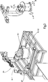
2 zeigt eine schematische Darstellung einer erfindungsgemäßen Vorrichtung 10 in einem ersten Aspekt, zum Beispiel zur Verwendung in einem System 1. 2 shows a schematic representation of a device according to the invention 10 in a first aspect, for example for use in a system 1 ,
Das System 1 umfasst die Vorrichtung 10, den Transportbehälter 20, eine optional Lineareinheit 30, einen optionalen Computer 40 und eine optionale Datenbank 50.The system 1 includes the device 10 , the transport container 20 , an optional linear unit 30 , an optional computer 40 and an optional database 50 ,
Die Vorrichtung 10 umfasst ein Beleuchtungssystem 101, das eingerichtet ist, um Schnittkanten von Profilen 201 derart zu beleuchten, dass die Schnittkanten relativ hell gegenüber den verbleibenden Abschnitten der Profile 201 erscheinen. Dies ist in Verbindung mit 6 näher erläutert.The device 10 includes a lighting system 101 which is set up to cut edges of profiles 201 to illuminate such that the cut edges are relatively bright compared to the remaining sections of the profiles 201 appear. This is in connection with 6 explained in more detail.
Außerdem umfasst die Vorrichtung 10 ein Bilderkennungssystem 102 mit einer Kamera 1021, das eigerichtet ist, um ein Bild zumindest eines Teilbereichs der Schnittkanten aufzunehmen, die Schnittkanten basierend auf einem Kantenmodell aus dem Bild zu erkennen, Positionen der Schnittkanten mit einer Breitenkomponente und einer Höhenkomponente zu ermitteln, und die Position derjenigen Schnittkante des Profils 201 mit der höchsten Höhenkomponente in dem Teilbereich zu bestimmen. Diese Merkmale sind in Verbindung mit 4A bis 4C und 5 näher erläutert.In addition, the device includes 10 an image recognition system 102 with a camera 1021 adapted to receive an image of at least a portion of the cut edges, to recognize the cut edges based on an edge model from the image, to determine positions of the cut edges having a width component and a height component, and the position of that cut edge of the profile 201 with the highest altitude component in the subarea. These features are in conjunction with 4A to 4C and 5 explained in more detail.
Schließlich umfasst die Vorrichtung 10 einen Roboter 103 mit einem Greifer 104, wobei der Roboter 103 eingerichtet ist, um mittels des Greifers 104 die bestimmte Position anzufahren und das entsprechende Profil 201 zu vereinzeln. Einzelheiten des Roboters 103 sind in Verbindung mit 3 erläutert, der Greifer 104 wird näher beschrieben in Verbindung mit 7, 8, 9A und 9B erläutert.Finally, the device includes 10 a robot 103 with a gripper 104 , where the robot 103 is set up by means of the gripper 104 to approach the specific position and the corresponding one profile 201 to separate. Details of the robot 103 are in connection with 3 explains the gripper 104 is described in more detail in connection with 7 . 8th . 9A and 9B explained.
Der Transportbehälter 20 umfasst die Profile 201, wobei die Schnittkanten (bzw. Stirnseiten) der Profile 201 im Wesentlichen bündig bezüglich des Transportbehälters 20 überstehen.The transport container 20 includes the profiles 201 , wherein the cut edges (or end faces) of the profiles 201 essentially flush with respect to the transport container 20 survive.
Die Lineareinheit 30 umfasst eine Längsrolle 301, und ist in Verbindung mit 10 näher beschrieben. Außerdem umfasst das System noch den Computer 40 und die Datenbank 50, wobei letztere näher in Verbindung mit 5 beschrieben ist.The linear unit 30 includes a longitudinal roll 301 , and is in connection with 10 described in more detail. In addition, the system still includes the computer 40 and the database 50 , the latter being more closely related to 5 is described.
3 zeigt einen Roboter 103 mit Greifer 104 zur Verwendung in der erfindungsgemäßen Vorrichtung 10. 3 shows a robot 103 with gripper 104 for use in the device according to the invention 10 ,
Ohne Beschränkung der Allgemeinheit ist in der Vorrichtung 10 zum automatisierten Vereinzeln und Zuführen von Profilen 201 zu einer Konfektionieranlage ein Roboter 103 vom Typ KR 16-2 S der Fa. KUKA eingesetzt. Die Antriebsleistung dieses Typs in den Grundachsen 1, 2 und 3 ermöglicht bis zu 18% kürzere Taktzeiten bei Entnahmezyklen gegenüber der Produktfamilie KR 16-2. Die technischen Daten des Roboters 103 KR 16-2 S sind in Tabelle 1 aufgelistet. Maximale Reichweite 1,611 mm
Nenntraglast 16 kg
Anzahl Achsen 6
Positionsgenauigkeit (nach ISO 9283 ) ±0,05 mm
Gewicht ca. 235 kg
Temperatur bei Betrieb +5°C bis +55°C
Aufstellfläche Roboter 103 500 mm × 500 mm
Anschluss 7,3 kVA
Geräuschpegel < 75 dB
Tabelle 1: Technische Daten des Roboters 103 KUKA KR 16-2 S Without limitation of generality is in the device 10 for automated separation and feeding of profiles 201 to a packaging plant a robot 103 Type KR 16-2 S from KUKA. The drive power of this type in the basic axes 1, 2 and 3 enables up to 18% shorter cycle times for removal cycles compared to the KR 16-2 product family. The technical data of the robot 103 KR 16-2 S are listed in Table 1. Maximum range 1,611 mm
nominal load 16 kg
Number of axes 6
Position accuracy (after ISO 9283 ) ± 0.05 mm
Weight about 235 kg
Temperature during operation + 5 ° C to + 55 ° C
Set-up robot 103 500 mm × 500 mm
connection 7.3 kVA
noise <75 dB
Table 1: Technical data of the robot 103 KUKA KR 16-2 S
4A bis 4C zeigen prinzipiell die Funktionsweise der Bilderkennung und -verarbeitung in der erfindungsgemäßen Vorrichtung. 4A to 4C show in principle the operation of the image recognition and processing in the device according to the invention.
Vor der Entnahme eines Profils 201 aus dem Transportbehälter 20 wird mit der Kamera 1021 ein Bild der Profile 201 im Behälter 20 aufgenommen. Die Kamera 1021 ist vorzugsweise frontal in orthogonaler Orientierung vor dem Transportbehälter 20 angeordnet, so dass die Profile 201 im Kamerabild im Schnitt dargestellt werden (vgl. 4A).Before taking a profile 201 from the transport container 20 is with the camera 1021 a picture of the profiles 201 in the container 20 added. The camera 1021 is preferably frontal in orthogonal orientation in front of the transport container 20 arranged so that the profiles 201 in the camera image are shown in section (see. 4A ).
Mit der eingesetzten Beleuchtung 101, welche nachstehend genauer beschrieben wird, wird ein Bild aufgenommen, in dem die Schnittkanten der Profile 201 hell abgebildet sind, während die weitere Oberfläche sowie die Umgebung der Profile 201 dunkel erscheint (vgl. 4A).With the lighting used 101 , which will be described in more detail below, an image is taken in which the cut edges of the profiles 201 are bright, while the other surface as well as the environment of the profiles 201 appears dark (cf. 4A ).
Bei einer Bildaufnahme wird nicht der gesamte Behälter 20 erfasst, sondern nur ein Bereich aufgenommen. Wie in 4B dargestellt, ist die Behälterbreite vorzugsweise in vier sich überlappende Bildfelder eingeteilt. Um die gesamte Breite des Transportbehälters 20 zu erfassen, befinden sich die Komponenten der Bildaufnahme auf einer Linearachse. In einem definierten Ablauf werden nacheinander die vier Positionen (Bildfeld 1 bis 4) auf der Linearachse angefahren, um eine gleichmäßige Entnahme der Profile 201 aus dem Transportbehälter 20 zu erzielen.Taking a picture does not take up the entire container 20 recorded, but only one area added. As in 4B 1, the container width is preferably divided into four overlapping image fields. Around the entire width of the transport container 20 To capture, the components of the image recording are on a linear axis. In a defined sequence, the four positions (image field 1 to 4) on the linear axis are successively approached, in order to obtain a uniform removal of the profiles 201 from the transport container 20 to achieve.
Die Unterteilung der gesamten Breite des Transportbehälters 20 wird vorgenommen, um vorzugsweise die im Bild erfassten Profile 201 mit einer solchen Auflösung abzubilden, dass eine sichere Erkennung durchgeführt werden kann. Zudem wird die Genauigkeit der Positionsermittlung des Profils 201 im Bild verbessert, so dass der Roboter 103 für den anschließenden Greifprozess exakt positioniert werden kann. Ist die Auflösung der Profile 201 im Kamerabild zu gering, kann dies Fehlerkennungen verursachen. Wie in 4B dargestellt, ist der ausgewertete Bildbereich 21 ein Teil des Bildfeldes (zum Beispiel Bildfeld 2). Da die Profile 201 vorzugsweise nur aus der oberen Lage aus dem Transportbehälter 20 entnommen werden, ist der Auswertebereich 22 gegenüber dem Bildbereich eingrenzt. Aufgrund dieser Eingrenzung wird die Auswertezeit verringert, weil weniger Kanten im Bild analysiert werden müssen.The subdivision of the entire width of the transport container 20 is made to preferably the captured in the image profiles 201 with a resolution such that a secure detection can be performed. In addition, the accuracy of the position detection of the profile 201 improved in the picture, so that the robot 103 can be accurately positioned for the subsequent gripping process. Is the resolution of the profiles 201 too low in the camera image, this can cause false detections. As in 4B is the evaluated image area 21 a part of the image field (for example image field 2). Because the profiles 201 preferably only from the upper layer of the transport container 20 are taken, is the evaluation area 22 limited to the image area. Due to this limitation, the evaluation time is reduced because fewer edges in the image need to be analyzed.
Wie in 4C gezeigt, nachdem die Kamera 1021 in eine vorbestimmte Position gefahren wurde, wird die Bildaufnahme ausgelöst. Über eine entsprechend parametrierte Mustererkennung werden die Profile 201 im Bild detektiert. Aus allen im Bild erkannten Profilen 201 wird das nächste zu greifende Profil 201 ausgewählt, dessen Referenzpunkt Sk2 den größten y-Wert (Höhenkomponente) aufweist. Profile 201 im Randbereich des Bildes werden ausgeblendet (vgl. 4C, Sk4). Diese Profile 201 könnten durch unvollständig im Bild liegende Profile 201 verdeckt sein. Profile 201, welche nicht vollständig im Bild abgebildet sind, werden von dem Bildverarbeitungssystem 102 vorzugsweise nicht detektiert.As in 4C shown after the camera 1021 has been moved to a predetermined position, the image acquisition is triggered. A corresponding parameterized pattern recognition makes the profiles 201 detected in the picture. From all profiles recognized in the image 201 becomes the next profile to take 201 whose reference point Sk2 has the largest y-value (height component). profiles 201 in the border area of the image are hidden (cf. 4C , Sk4). These profiles 201 could be due to incomplete picture lying profiles 201 be covered. profiles 201 which are not fully pictured are used by the image processing system 102 preferably not detected.
Zudem wird bei der Auswertung vorzugsweise der Winkel α der Profile 201 im Bild ermittelt (vgl. 4C, Sk1). Überschreitet der ermittelte Wert des Winkels α für ein Profil 201 einen zuvor festgelegten Parameter, wird dieses Profil 201 für den nächsten Vereinzelungsvorgang ausgeschlossen. Des Weiteren wird überprüft, ob bei der Entnahme eines Profils 201 eine Kollision mit einem benachbarten Profil 201 auftreten kann. So wird z. B. das Profil 201 (Sk3) am rechten Bildrand ausgeschlossen, weil ein anderes Profil 201 über diesem Profil 201 liegt.In addition, in the evaluation, preferably the angle α of the profiles 201 determined in the picture (cf. 4C , Sk1). Exceeds the determined value of the angle α for a profile 201 a previously defined parameter, this profile becomes 201 excluded for the next separation process. It also checks if you are taking a profile 201 a collision with an adjacent profile 201 can occur. So z. B. the profile 201 (Sk3) on the right edge excluded because of a different profile 201 above this profile 201 lies.
In 4C wird das Profil 201 (Sk2) für die Entnahme aus dem Transportbehälter 20 ausgewählt. Die im Bild ermittelten Koordinatenwerte (x1, y1) und vorzugsweise der Winkel α des Profils 201 werden an den Roboter 103 übermittelt. Der Roboter 103 bewegt den Greifer 104 in die entsprechende Position und Orientierung und greift das Profil 201.In 4C becomes the profile 201 (Sk2) for removal from the transport container 20 selected. The coordinate values (x1, y1) determined in the image and preferably the angle α of the profile 201 be to the robot 103 transmitted. The robot 103 moves the gripper 104 in the appropriate position and orientation and engages the profile 201 ,
In Abhängigkeit der Geometrie der Profile 201 wird das Greifen und Vereinzeln eines Profils 201 durchgeführt. Wie nachstehend unter Bezugnahme auf 8 näher ausgeführt, werden bei Hohlprofilen 201 die Finger des Greifers 104 in der Regel in die Hohlkammer eingeführt und das Profil 201 gegriffen. Wie nachstehend unter Bezugnahme auf 9A und 9B gezeigt, werden die Flachprofile 201 vor dem Greifen vorzugsweise mit einem Schieber am Geifer vorvereinzelt. Dabei wird das zugreifende Profil 201 um einige Millimeter aus dem Transportbehälter 20 herausgezogen.Depending on the geometry of the profiles 201 becomes grasping and singulating a profile 201 carried out. As explained below with reference to 8th be explained in more detail, be in hollow sections 201 the fingers of the gripper 104 usually introduced into the hollow chamber and the profile 201 resorted. As explained below with reference to 9A and 9B Shown are the flat profiles 201 before grasping it is preferable to sing with a slider on the fiddler. This is the accessing profile 201 by a few millimeters from the transport container 20 pulled out.
Die Komponenten der Bildaufnahme sind vorzugsweise auf einer (weiteren) Lineareinheit montiert. Befinden sich bei mehreren hintereinander durchgeführten Entnahmen die ausgewählten Profile 201 am unteren Rand des Auswertebereichs, das heißt, der y-Wert des ausgewählten Profils 201 liegt nah an der unteren Rand des Auswertebereichs, wird von der Bildverarbeitung 102 ein entsprechendes Signal ausgegeben, um die vorzugsweise vorhandene Hubeinrichtung 202, auf welcher der Transportbehälter 20 steht, einen definierten Weg nach oben zu heben.The components of the image recording are preferably mounted on a (further) linear unit. If several withdrawals have been made consecutively, the selected profiles are located 201 at the bottom of the evaluation area, that is, the y-value of the selected profile 201 is close to the bottom of the evaluation area, is used by the image processing 102 a corresponding signal output to the preferably existing lifting device 202 on which the transport container 20 is to lift a defined way up.
Wie nachstehend näher unter Bezugnahme auf 10 beschrieben, nachdem ein Profil 201 gegriffen wurde, wird es in einer definierten Orientierung in die Lineareinheit 30 übergeben. Dabei wird das Profil 201 um eine Längsrolle 301 herumgeführt. Die Längsrolle dient dazu, dass die Profile 201 seitlich aus dem Transportbehälter 20 herausgezogen werden. Auf diese Weise wird nur das gegriffene Profil 201 aus dem Transportbehälter 20 herausgezogen, auch wenn andere Profile 201 teilweise über diesem Profil 201 liegen. Der Greifer 104 an der Lineareinheit übernimmt das Profil 201 aus dem Roboter 103 Greifer 104 und führt das Profil 201 in die Konfektionieranlage ein. Während das Profil 201 von der Lineareinheit aus dem Transportbehälter 20 herausgezogen wird, wird die Kamera 1021 bereits für die nächste Bildaufnahme positioniert und der Roboter 103 in die Ausgangsposition gefahren.As further described below with reference to 10 described after a profile 201 it is in a defined orientation in the linear unit 30 to hand over. This is the profile 201 around a longitudinal roll 301 led around. The longitudinal roll serves to ensure that the profiles 201 laterally from the transport container 20 be pulled out. In this way, only the gripped profile 201 from the transport container 20 pulled out, even if other profiles 201 partly over this profile 201 lie. The gripper 104 The profile is taken over by the linear unit 201 from the robot 103 grab 104 and leads the profile 201 into the packaging plant. While the profile 201 from the linear unit from the transport container 20 is pulled out, the camera becomes 1021 already positioned for the next image capture and the robot 103 moved to the starting position.
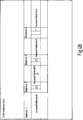
5 zeigt eine Datenbank 50 zur Verwendung in der erfindungsgemäßen Vorrichtung 10. 5 shows a database 50 for use in the device according to the invention 10 ,
Wie beschrieben, detektiert das Bildverarbeitungssystem 102 anhand eines Modells 51 des Profils 201 die im Transportbehälter 20 befindlichen Profile 201. Entsprechend dem hinterlegten Modell 51 des Hohlprofils 201 wird das mit Bezugszeichen 51a) dargestellte Modell des Profils 201 im Bildverarbeitungssystem 102 hinterlegt. Liegen die Profile 201 jedoch anders herum (z. B. gespiegelt) im Transportbehälter 20 bzw. wird der Transportbehälter 20 um 180° gedreht vor der Anlage positioniert, so dass die Profile 201 wie mit Bezugszeichen 51b) vor der Kamera 1021 liegen, werden diese Profile 201 bei der Bildauswertung nicht detektiert werden.As described, the image processing system detects 102 based on a model 51 of the profile 201 in the transport container 20 located profiles 201 , According to the deposited model 51 of the hollow profile 201 this is the reference number 51a ) illustrated model of the profile 201 in the image processing system 102 deposited. Are the profiles lying down? 201 but the other way round (eg mirrored) in the transport container 20 or is the transport container 20 rotated by 180 ° positioned in front of the plant, leaving the profiles 201 as with reference numerals 51b ) in front of the camera 1021 lie, these profiles become 201 can not be detected during image evaluation.
Durch Verwendung bzw. Hinterlegung des gespiegelten Modells 51 ist auch die Erfassung umgekehrt liegender Profile 201 möglich. Das Greifen umgekehrt liegender Profile 201 kann z. B. durch einen um 360° drehbaren Greifer 104 gelöst werden. By using or depositing the mirrored model 51 is also the detection of inverted profiles 201 possible. The gripping of inverted profiles 201 can z. B. by a rotatable by 360 ° gripper 104 be solved.
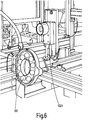
6 zeigt ein Beleuchtungssystem 101 zur Verwendung in der erfindungsgemäßen Vorrichtung. 6 shows a lighting system 101 for use in the device according to the invention.
Die Profile 201 liegen nicht magaziniert in dem Transportbehälter 20. Um die Profile 201 automatisiert greifen zu können, müssen die Profile 201 im Transportbehälter 20 erkannt werden. Dabei besteht die besondere Herausforderung darin, dass diese Profile 201 z. B. aus schwarzem Kunststoff gefertigt sein können.The profiles 201 are not stored in the transport container 20 , To the profiles 201 to be able to automatically grasp the profiles, 201 in the transport container 20 be recognized. The particular challenge is that these profiles 201 z. B. can be made of black plastic.
Zur Bildaufnahme wird vorzugsweise eine Grauwertmatrixkamera 1021 vom Typ Iris GT mit 640×480 Pixeln der Fa. Matrox eingesetzt; dies ist lediglich eine Beispielimplementierung und schränkte die Erfindung nicht ein. An dieser Kamera 1021 ist vorzugsweise ein Objektiv mit einer Brennweite von 25 mm der Fa. Pentax angeschraubt. In Vorversuchen wurden für diese Aufgabenstellung unterschiedliche Beleuchtungsquellen und Beleuchtungsarten untersucht. Die Art der Beleuchtung beeinflusst die nachfolgende Bildauswertung und ist daher sorgfältig zu wählen. Die Beleuchtung dient dazu, die interessierenden Objekteigenschaften kontrastreich im Bild darzustellen. Es zeigte sich, dass eine Ringlichtbeleuchtung für diese Aufgabe insbesondere geeignet ist. Zur Bildaufnahme wird daher vorzugsweise eine LED-Ringleuchte vom Typ MRL 5.5 der Fa. Spectrum Illumination ausgewählt. Diese Beleuchtung sendet Licht im blauen Wellenlängenbereich aus. Zudem ist in den Strahlengang ein Bandpassfilter 10211 vorzugsweise der Fa. Jos. Schneider Optische Werke GmbH eingebracht, das nur Licht im blauen Wellenlängenbereich durchlässt. Die Anordnung der Kamera 1021 mit Objektiv und der Ringbeleuchtung 101 auf der Linearachse ist in 6 dargestellt.For image acquisition, a gray value matrix camera is preferably used 1021 type Iris GT with 640 × 480 pixels from Matrox used; this is just an example implementation and does not limit the invention. At this camera 1021 is preferably a lens with a focal length of 25 mm of Fa. Pentax screwed. In preliminary experiments, different lighting sources and types of lighting were investigated for this task. The type of lighting influences the subsequent image analysis and should therefore be chosen carefully. The lighting is used to represent the object properties of interest in high contrast in the image. It turned out that a ring light illumination is particularly suitable for this task. Therefore, an LED ring lamp of the MRL 5.5 type from Spectrum Illumination is preferably selected for image acquisition. This illumination emits light in the blue wavelength range. In addition, a bandpass filter is in the beam path 10211 preferably from the company Jos. Schneider Optische Werke GmbH, which transmits only light in the blue wavelength range. The arrangement of the camera 1021 with lens and the ring illumination 101 on the linear axis is in 6 shown.
Wie beschrieben, beeinflusst die Beleuchtung 102 die Bildauswertung. Sich verändernde Lichtverhältnisse wie einfallendes Sonnenlicht oder Fremdlicht durch die Hallenbeleuchtung wirken sich häufig störend auf die Bildanalyse aus. Bei der Erkennung der Profile 201 wird deshalb eine Beleuchtung 102 eingesetzt, die vorzugsweise im blauen Wellenbereich aussendet. Wie erwähnt, wird in den Strahlengang z. B. vor dem Bildsensor der Kamera 1021 das Bandpassfilter 10211 eingesetzt, das nur Licht im blauen Wellenlängenbereich durchlässt. Auf diese Weise wird Fremdlicht weitestgehend ausgeschlossen, so dass keine mechanischen Abschottungen erforderlich sind.As described, the lighting influences 102 the image analysis. Changing lighting conditions such as incident sunlight or ambient light through the hall lighting often interfere with the image analysis. When detecting the profiles 201 therefore becomes a lighting 102 used, which preferably emits in the blue wavelength range. As mentioned, in the beam path z. B. in front of the image sensor of the camera 1021 the bandpass filter 10211 used, which allows only light in the blue wavelength range. In this way, extraneous light is largely excluded, so that no mechanical foreclosures are required.
In der Bildauswertung erfolgt die Analyse des aufgenommenen Bildes. Zur Erkennung der Profile 201 werden die Kanten im Bild 21, 22 ermittelt. Die gefundenen Kanten werden vorzugsweise mit einem Kantenmodell 51 des zu vereinzelnden Profils 201 verglichen. Das Kantenmodell 51 wurde zuvor in der Bildverarbeitungssoftware hinterlegt. Anhand dieses Vergleichs werden die Profile 201 im Bild detektiert. Zu den gefundenen Kanten werden die Position im Bild sowie die Neigung des Profils 201 angegeben.In the image analysis, the analysis of the recorded image takes place. To recognize the profiles 201 be the edges in the picture 21 . 22 determined. The found edges are preferably with an edge model 51 of the profile to be separated 201 compared. The edge model 51 was previously deposited in the image processing software. Based on this comparison, the profiles 201 detected in the picture. The found edges are the position in the picture as well as the inclination of the profile 201 specified.
Die ermittelte Position x, y und vorzugsweise Orientierung α eines Profils 201 werden als Ergebnis der Bildanalyse vorzugsweise in Form eines Steuersignals an den Roboter 103 abgeben. Der Roboter 103 übernimmt dieses Signal als Korrekturwert für die Steuerung, um das Profil 201 im nächsten Schritt greifen zu können. Damit der Roboter 103 entsprechend den von der Bildverarbeitung 102 übermittelten Daten die Position anfahren kann, ist es erforderlich, dass zwischen den Ergebniswerten des Bildverarbeitungssystems und dem Koordinatensystems des Roboters 103 eine Beziehung hergestellt wird.The determined position x, y and preferably orientation α of a profile 201 are preferably in the form of a control signal to the robot as a result of the image analysis 103 submit. The robot 103 adopts this signal as a correction value for the controller to the profile 201 to take action in the next step. So that the robot 103 according to the image processing 102 transmitted data can approach the position, it is necessary that between the result values of the image processing system and the coordinate system of the robot 103 a relationship is established.
Unter Rückbezug auf 4C ist das Koordinatensystem des Bildverarbeitungssystems 102 eingezeichnet; das Weltkoordinatensystem des Roboters 103 ist 3 dargestellt. Diese Beziehung zwischen diesen Koordinatensystemen wird durch eine Kalibrierung erzeugt. Da die Kamera 1021 mit dem Objektiv sowie der Roboter 103 vorzugsweise auf einem Grundgestell montiert sind, genügt es in der Regel, diese Kalibrierung einmalig bei der Inbetriebnahme der Anlage durchzuführen.With reference to 4C is the coordinate system of the image processing system 102 drawn; the world coordinate system of the robot 103 is 3 shown. This relationship between these coordinate systems is created by calibration. Because the camera 1021 with the lens as well as the robot 103 are preferably mounted on a base frame, it is usually sufficient to carry out this calibration once during commissioning of the system.
Die Kalibrierung des Bildverarbeitungssystems 102 des Roboters 103 wird in einer zuvor definierten Ebene durchgeführt. Um eine sichere Bildauswertung und anschließendes Greifen eines Profils 201 zu gewährleisten, müssen die Profilenden im Transportbehälter 20 möglichst exakt in der Ebene liegen, in welcher zuvor die Kalibrierung durchgeführt wurde. Zudem wird bei der Bildauswertung auch die Größe der im Bild erkannten Profilgeometrie mit dem Kantenmodell 51 des Profils 201 verglichen. Weicht die Größe eines im Bild ermittelten Profils 201 über einen voreingestellten Wert von dem Kantenmodell 51 ab, wird dieses Profil 201 in der weiteren Bildauswertung nicht weiter berücksichtigt. Aus diesem Grund müssen die Profile 201 bündig abschließend in dem Transportbehälter 20 liegen; die Profilenden (bzw. Stirnseiten oder Kanten) liegen vorzugsweise in einem Bereich von ±3 mm in der Kalibrierebene. Um auch Profile 201 am linken sowie am rechten Rand des Transportbehälters 20 greifen zu können, stehen die Profile 201 an der Entnahmeseite vorzugsweise um etwa 200 mm über. Ist dies nicht der Fall, kann der Greifer 104 bei der Entnahme solcher Profile 201 mit dem Transportbehälter 20 kollidieren.The calibration of the image processing system 102 of the robot 103 is performed in a previously defined level. For a secure image analysis and subsequent grabbing of a profile 201 to ensure the tread ends in the transport container 20 lie as exactly as possible in the plane in which the calibration was previously performed. In addition, the image evaluation also determines the size of the profile geometry recognized in the image using the edge model 51 of the profile 201 compared. Differs the size of a profile found in the image 201 over a preset value from the edge model 51 off, this profile becomes 201 not considered further in the further image analysis. Because of this, the profiles need 201 flush in the transport container 20 lie; the profile ends (or end faces or edges) are preferably in a range of ± 3 mm in the calibration plane. To profiles too 201 on the left and on the right edge of the transport container 20 to be able to grab the profiles 201 at the removal side preferably about 200 mm across. If this is not the case, the gripper can 104 when removing such profiles 201 with the transport container 20 collide.
7 zeigt eine Prinzipskizze eines Greifers 104 zur Verwendung in der erfindungsgemäßen Vorrichtung. 7 shows a schematic diagram of a gripper 104 for use in the device according to the invention.
Beim Greifen eines Profils 201 wird zwischen Hohlprofil und Flachprofil unterschieden. In 7 ist ein Greifer 104 für ein Hohlprofil 201 schematisch dargestellt. Zum Greifen des Profils 201 dringen die zwei Finger 1041, 1042 des Greifers 104 in die Hohlkammer ein und werden geschlossen. Auf diese Weise wird das Profil 201 gegriffen.When gripping a profile 201 is distinguished between hollow profile and flat profile. In 7 is a gripper 104 for a hollow profile 201 shown schematically. For gripping the profile 201 penetrate the two fingers 1041 . 1042 of the gripper 104 in the hollow chamber and are closed. That way, the profile becomes 201 resorted.
8 zeigt ein erstes Beispiel eines Greifers 104 zur Verwendung bei der erfindungsgemäßen Vereinzelung von Hohlprofilen 201. 8th shows a first example of a gripper 104 for use in the singulation of hollow sections according to the invention 201 ,
Mit den in 7 schematisch dargestellten Greifer 104 können Hohlprofile 201 wie in gegriffen und der Lineareinheit zugeführt werden. Große Hohlprofile 201 wie in 1 sind hingegen deutlich steifer als die kleinen Hohlprofile 201. Um bei den großen Hohlprofilen 201 eine Beschädigung beim Greifen zu vermeiden, wurde für diese Profile 201 der in Greifer 104 für kleine Hohlprofile 201 modifiziert. Wie in 8 dargestellt, wird die obere Backe 1042 des Greifers 104 auf dem Profil 201 aufgesetzt, während die untere Backe 1041 in eine Hohlkammer des Profils 201 eindringt. Die obere Backe 1042 ist vorzugsweise auf der unteren Seite mit einem rutschfesten Material ausgestattet, um einen sicheren Halt des Profils 201 im Greifer 104 zu gewährleisten.With the in 7 schematically illustrated gripper 104 can hollow sections 201 as in gripped and fed to the linear unit. Large hollow profiles 201 as in 1 On the other hand, they are much stiffer than the small hollow profiles 201 , To the large hollow sections 201 To avoid damage when gripping was for these profiles 201 the one in grapple 104 for small hollow profiles 201 modified. As in 8th pictured, the upper jaw becomes 1042 of the gripper 104 on the profile 201 put on while the lower jaw 1041 in a hollow chamber of the profile 201 penetrates. The upper cheek 1042 is preferably equipped on the lower side with a non-slip material to ensure a secure hold of the profile 201 in the gripper 104 to ensure.
9A und 9B zeigen ein zweites Beispiel eines Greifers 104 zur Verwendung bei der erfindungsgemäßen Vereinzelung von Flachprofilen 201. 9A and 9B show a second example of a gripper 104 for use in the separation of flat profiles according to the invention 201 ,
Bei Flachprofilen 201 kann ein Greifer 104, der ähnlich ausgeführt ist wie der in 7 und 8 dargestellte Greifer 104 für Hohlprofile 201, nicht eingesetzt werden. Soll mit dem Zwei-Backen-Greifer 104 ein Profil 201 aus der obersten Ebene des Transportbehälters 20 entnommen werden, kann durch die untere Backe des Greifers 104 ein Profil 201, welches unter dem ausgewählten Profil 201 liegt, beim Anfahren aus dem Transportbehälter 20 nach hinten herausgeschoben wird. Um dies zu verhindern, findet vorzugsweise vor dem Greifen eines Flachprofils 201 eine Vorvereinzelung statt.For flat profiles 201 can be a gripper 104 , which is similar to the one in 7 and 8th illustrated gripper 104 for hollow profiles 201 , not used. Target with the two-jaw gripper 104 a profile 201 from the top level of the transport container 20 can be removed through the lower jaw of the gripper 104 a profile 201 which is under the selected profile 201 is when starting from the transport container 20 pushed out to the rear. To prevent this, preferably takes place before gripping a flat profile 201 a pre-separation takes place.
Die Vorvereinzelung dient dazu, dass zu greifende Flachprofil 201 aus dem Verbund zu lösen, ohne ein anderes Profil 201 im Transportbehälter 20 zu verschieben. Der erfindungsgemäße Greifer 104 für Flachprofile 201 besteht aus zwei Backen 1041, 1042. Die obere Backe 1042 ist feststehend und vorzugsweise auf der Unterseite mit einem rutschfesten Material ausgestattet. Des Weiteren sind vorzugsweise in diese Backe 1042 zumindest eine (vorzugsweise zwei) Saugdüsen 1043 eingelassen. Die untere Backe 1041 des Greifers 104 kann um vorzugsweise 90° geschwenkt werden.The pre-singling serves to that to be gripped flat profile 201 to release from the composite, without a different profile 201 in the transport container 20 to move. The gripper according to the invention 104 for flat profiles 201 consists of two cheeks 1041 . 1042 , The upper cheek 1042 is fixed and preferably equipped on the bottom with a non-slip material. Furthermore, preferably in this jaw 1042 at least one (preferably two) suction nozzles 1043 admitted. The lower cheek 1041 of the gripper 104 can be pivoted by preferably 90 °.
Wie in 9A gezeigt, ist beim Vorvereinzeln ist die untere Backe 1041 vorzugsweise zur Seite geschwenkt. Die obere Backe 1042 des Greifers 104 wird entsprechend den übermittelten Daten aus dem analysierten Kamerabild auf dem Flachprofil 201 aufgesetzt. Die beiden Düsen 1043 der oberen Backe saugen das Flachprofil 201 an. Das rutschfeste Material sorgt für einen sicheren Halt beim Herausziehen des Profils 201 aus dem Transportbehälter 20.As in 9A shown is in the pre-singling is the lower jaw 1041 preferably pivoted to the side. The upper cheek 1042 of the gripper 104 is calculated according to the transmitted data from the analyzed camera image on the flat profile 201 placed. The two nozzles 1043 the upper jaw suck the flat profile 201 at. The non-slip material ensures a secure grip when pulling out the profile 201 from the transport container 20 ,
Wie in 9B gezeigt, ist das Profil 201 aus dem Transportbehälter 20 vorvereinzelt, wird die untere Backe 1041 des Greifers 104 um vorzugsweise 90° unter die obere Backe 1042 geschwenkt und das Profil 201 gegriffen. An dem Flachprofilgreifer 104 ist vorzugsweise unterhalb der Greifeinheit eine senkrecht angeordnete Platte 1044 montiert. Wenn beim Vorvereinzeln eines Profils 201 ein weiteres Profil 201 mit aus dem Transportbehälter 20 herausgezogen wird, kann das nicht gegriffene Profil 201 mit Hilfe dieser Platte 1044 in den Transportbehälter 20 wieder eingeschoben werden.As in 9B shown is the profile 201 from the transport container 20 pretuned, the lower jaw becomes 1041 of the gripper 104 preferably at 90 ° below the upper jaw 1042 panned and the profile 201 resorted. On the flat profile gripper 104 is preferably below the gripping unit a vertically arranged plate 1044 assembled. When pre-dicing a profile 201 another profile 201 with out of the transport container 20 can pull out the unclipped profile 201 with the help of this plate 1044 in the transport container 20 be inserted again.
Es wurden die in 1 gezeigten vier Profile 201 untersucht. Anhand dieser Profile 201 wurden die beschriebenen Greifertypen entwickelt. Je nach Art und Größe der Profile 201 ist gegebenenfalls eine Modifizierung der vorgestellten Greifer 104 durchzuführen.It was the in 1 shown four profiles 201 examined. Based on these profiles 201 the described gripper types were developed. Depending on the type and size of the profiles 201 is possibly a modification of the presented gripper 104 perform.
Beim Wechsel eines Profils 201 müssen je nach Profil 201 gegebenenfalls der Robotergreifer 104, der Greifer der Lineareinheit sowie das Bildverarbeitungssystem 102 an das nächste zu verarbeitende Profil 201 angepasst werden. Wie vorstehend beschrieben, gibt es für unterschiedliche Profile 201 verschiedene Robotergreifer 104. Die unterschiedlichen Greifer 104 können in einem Magazin bereitgestellt werden, aus dem der Roboter 103 selbsttätig den aktuellen Greifer 104 absetzt und den erforderlichen Greifer 104 aufnimmt. Dazu müssen die Greifer 104 wie auch der Roboterflansch mit einer entsprechenden Schnellwechselkupplung ausgestattet werden.When changing a profile 201 have to be depending on the profile 201 if necessary, the robot gripper 104 , the gripper of the linear unit and the image processing system 102 to the next profile to be processed 201 be adjusted. As described above, there are different profiles 201 various robot gripper 104 , The different grippers 104 can be provided in a magazine that makes up the robot 103 automatically the current gripper 104 settles and the required gripper 104 receives. This requires the grippers 104 as well as the robot flange are equipped with a corresponding quick-change coupling.
Die Profile 201 werden im Greifer 104 der Lineareinheit vorzugsweise pneumatisch geklemmt. Um einen sicheren Halt in dem Greifer 104 zu gewährleisten, wird dieser Greifer 104 ähnlich wie der Robotergreifer 104 an die Profile 201 angepasst. Beim Wechsel eines Profils 201 wird der Greifer 104 der Lineareinheit manuell gewechselt.The profiles 201 be in the grapple 104 the linear unit preferably pneumatically clamped. For a secure hold in the gripper 104 to ensure this gripper is 104 similar to the robot gripper 104 to the profiles 201 customized. When changing a profile 201 becomes the gripper 104 the linear unit changed manually.
Für das nächste zu verarbeitenden Profil 201 muss das entsprechende Kantenmodell 51 im Bildverarbeitungssystem 102 ausgewählt werden. Dabei kann die Oberfläche des Bildverarbeitungssystems 102 so gestaltet werden, dass die bereits verfügbaren Kantenmodelle 51 z. B. mit der entsprechenden Artikelnummer hinterlegt sind. Durch Auswahl eines Profils 201 werden das entsprechende Kantenmodell 51 und die dazu hinterlegten Parameter geladen.For the next profile to be processed 201 must be the corresponding edge model 51 in the image processing system 102 to be selected. In this case, the surface of the image processing system 102 be designed so that the already available edge models 51 z. B. are deposited with the corresponding article number. By selecting a profile 201 become the corresponding edge model 51 and the stored parameters are loaded.
Um einen Transportbehälter 20 in einer definierten Position vor der Anlage abzustellen, sind an einem Grundgestell der Vorrichtung 10 Anschläge zur Positionierung des Transportbehälters 20 angebracht. Auf diese Weise wird sichergestellt, dass der Transportbehälter 20 orthogonal vor der Kamera 1021 steht und sich die Profile 201 im gleichen Abstand zur Kamera 1021 befinden.To a transport container 20 Park in a defined position in front of the system are on a base frame of the device 10 Stops for positioning the transport container 20 appropriate. This will ensure that the transport container 20 orthogonal in front of the camera 1021 stands and looks at the profiles 201 at the same distance from the camera 1021 are located.
10 zeigt einen zweiten Aspekt der Erfindung, ein System umfassend die erfindungsgemäße Vorrichtung 10 und eine Lineareinheit 30. 10 shows a second aspect of the invention, a system comprising the device according to the invention 10 and a linear unit 30 ,
Aufgrund der Steifigkeit eines großen Hohlkammerprofils 201 wird dieses bei der Übergabe in die Lineareinheit um 90° auf die schmale Seite gedreht. So kann ein solches Profil 201 um die Rolle 301 herum in den Greifer 104 der Lineareinheit gelegt werden. Bei der Übergabe dieses Profils 201 an die Konfektionieranlage kann das Profil 201 wieder um 90° in die breite Seite gedreht werden.Due to the rigidity of a large hollow section profile 201 this is rotated by 90 ° on the narrow side when transferred to the linear unit. So can such a profile 201 around the role 301 around in the claw 104 be placed the linear unit. When handing over this profile 201 the profile can be sent to the packaging plant 201 be turned 90 ° in the wide side again.
11 zeigt ein Zeitdiagramm betreffend den Betrieb der erfindungsgemäßen Vorrichtung 10. 11 shows a timing diagram relating to the operation of the device according to the invention 10 ,
In 11 ist das Zeitdiagramm für das Vereinzeln von Profilen 201 aus dem Transportbehälter 20 und das Zuführen in eine (nicht gezeigte) Konfektionieranlage abgebildet. Dabei wird der Fall eines Flachprofils 201 betrachtet, bei dem eine Vorvereinzelung stattfindet. Im Einzelnen werden vorzugsweise die folgenden Operationen durchgeführt:
- 1. Es wird ein Kamerabild der Profile 201 aufgenommen. Die Kamera 1021 wird zuvor positioniert, wenn das Profil 201 an die Lineareinheit 30 übergeben wird und der Roboter 103 in die Ausgangsposition fährt.
- 2. Entsprechend den übergebenen Daten des Bildverarbeitungssystems wird der Robotergreifer 104 zu dem ausgewählten Profil 201 gefahren.
- 3. Das ausgewählte Profil 201 wird vorvereinzelt.
- 4. Das vorvereinzelte Profil 201 wird gegriffen.
- 5. Das gegriffene Profil 201 wird zur Übergabe an die Lineareinheit 30 gebracht. Dabei wird es in die erforderliche Orientierung gebracht.
- 6. Das Profil 201 wird von der Lineareinheit 30 übernommen. Nach der Übernahme wird es der Konfektionieranlage zugeführt.
- 7. Der Roboter 103 fährt in die Ausgangsposition und erhält die Daten für das nächste zu vereinzelnde Profil 201.
In 11 is the time diagram for the separation of profiles 201 from the transport container 20 and imaging the supply into a packaging plant (not shown). This is the case of a flat profile 201 considered, in which a pre-separation takes place. More specifically, the following operations are preferably performed: - 1. It will be a camera image of the profiles 201 added. The camera 1021 is previously positioned when the profile 201 to the linear unit 30 is passed and the robot 103 moves to the starting position.
- 2. According to the transferred data of the image processing system becomes the robot gripper 104 to the selected profile 201 hazards.
- 3. The selected profile 201 is vorvereinzelt.
- 4. The pre-singled profile 201 is seized.
- 5. The gripped profile 201 is for transfer to the linear unit 30 brought. It is brought into the required orientation.
- 6. The profile 201 is from the linear unit 30 accepted. After the takeover, it is fed to the packaging plant.
- 7. The robot 103 moves to the starting position and receives the data for the next profile to be singled 201 ,
12 zeigt eine Schutzumhausung 60 zur Verwendung mit der erfindungsgemäßen Vorrichtung 10. 12 shows a protective housing 60 for use with the device according to the invention 10 ,
Die Schutzumhausung 60 umschließt vorzugsweise sowohl das Grundgestell mit den aufgebauten Komponenten wie auch den Transportbehälter 20 ein. Die Bewegung der Hubeinheit 202 wird derzeit manuell ausgelöst. Diese Bewegung wird erfindungsgemäß entsprechend der Lage der Profile 201 im Auswertebereich des Kamerabildes automatisiert ausgeführt. Daher ist es erforderlich, sowohl das Grundgestell als auch die Hubeinheit 202 mit dem Transportbehälter 20 mit der Schutzumhausung 60 zu umschließen. Um den Transportbehälter 20 in die Anlage einbringen zu können, verfügt die Schutzumhausung über Flügeltüren.The protective housing 60 preferably encloses both the base frame with the components constructed as well as the transport container 20 one. The movement of the lifting unit 202 is currently triggered manually. This movement is inventively according to the position of the profiles 201 automatically executed in the evaluation area of the camera image. Therefore, it is necessary both the base frame and the lifting unit 202 with the transport container 20 with the protective housing 60 to enclose. To the transport container 20 into the system, the protective enclosure has double doors.
13 zeigt eine Prinzipskizze einer Notfallkonfiguration 70 zur Verwendung mit der erfindungsgemäßen Vorrichtung 10. 13 shows a schematic diagram of an emergency configuration 70 for use with the device according to the invention 10 ,
Beim Ausfall des Roboters 103, des Bildverarbeitungssystems 102 oder der Lineareinheit 30 soll die Zuführung der Profile 201 zur Konfektionieranlage in einer Notkonfiguration weiter betrieben werden können. In der Notkonfiguration können die Profile 201 manuell aus dem Transportbehälter 20 entnommen und der Konfektionieranlage zugeführt werden. In case of failure of the robot 103 , the image processing system 102 or the linear unit 30 should the feeding of the profiles 201 can continue to operate the assembly plant in an emergency configuration. In the emergency configuration, the profiles 201 manually from the transport container 20 removed and fed to the confectioning system.
Wie in 13 gezeigt, befindet sich für die Notkonfiguration neben der Lineareinheit 30 auf dem Grundgestell eine Führungsschiene. Diese Führungsschiene wird für die Notkonfiguration manuell so gedreht, dass diese Führungsschiene in einer Flucht mit dem Einzug der Konfektionieranlage steht. Es findet eine manuelle Zuführung eines Profils 201 aus dem Transportbehälter 20 über die Führungsschiene in die Konfektionieranlage statt. Der Roboter 103 wird in der Notkonfiguration in eine zuvor definierte Stellung gefahren. Nur wenn der Roboter 103 in dieser Stellung steht, kann die Notkonfiguration gestartet werden.As in 13 shown is located next to the linear unit for the emergency configuration 30 a guide rail on the base frame. This guide rail is manually rotated for the emergency configuration so that this guide rail is in alignment with the feeder of the assembly line. There is a manual feed of a profile 201 from the transport container 20 via the guide rail into the assembly plant. The robot 103 is moved in the emergency configuration in a previously defined position. Only if the robot 103 is in this position, the emergency configuration can be started.
14 schließlich zeigt einen Verfahrensaspekt der erfindungsgemäßen Vorrichtung 10. 14 Finally, shows a method aspect of the device according to the invention 10 ,
Erfindungsgemäß ist ein Verfahren zum Steuern der Vorrichtung 10 zur automatisierten Vereinzelung der nicht-magazinierten Profilen 201 aus dem Transportbehälter 20 vorgesehen, wobei die Schnittkanten der Profile 201 im Wesentlichen bündig bezüglich des Transportbehälters 20 überstehen. Das Verfahren umfasst die Schritte Beleuchten S1, mittels des Beleuchtungssystems 101, der Schnittkanten der Profile 201 derart, dass die Schnittkanten relativ hell gegenüber den verbleibenden Abschnitten der Profile 201 erscheinen, Aufnehmen S2, mittels des Bilderkennungssystems 102 mit einer Kamera 1021, eines Bildes zumindest eines Teilbereichs 21, 22 der Schnittkanten, Erkennen S3, mittels des Bilderkennungssystems, der Schnittkanten aus dem Bild basierend auf einem Kantenmodell, Ermitteln S4, mittels des Bilderkennungssystems, von Positionen der Schnittkanten mit einer Breitenkomponente x1 bis xn und einer Höhenkomponente y1 bis yn, Bestimmen S5 der Position derjenigen Schnittkante des Profils 201 mit der höchsten Höhenkomponente in dem Teilbereich, Anfahren S6, mittels des Roboters 103 mit dem Greifer 104, der bestimmten Position, und Vereinzeln S7, mittels des Roboters 103 mit dem Greifer 104, des entsprechenden Profils 201 bei der angefahrenen Position.According to the invention, a method for controlling the device 10 for the automated separation of non-magazine profiles 201 from the transport container 20 provided, wherein the cut edges of the profiles 201 essentially flush with respect to the transport container 20 survive. The method comprises the steps illuminate S1, by means of the illumination system 101 , the cutting edges of the profiles 201 such that the cut edges are relatively bright relative to the remaining portions of the profiles 201 appear, recording S2, by means of the image recognition system 102 with a camera 1021 , an image of at least one subarea 21 . 22 the cutting edges, detecting S3, by means of the image recognition system, the cut edges from the image based on an edge model, determining S4 by means of the image recognition system, from positions of the cut edges with a width component x1 to xn and a height component y1 to yn, determining S5 the position of that cut edge of the profile 201 with the highest altitude component in the subsection, approach S6, by means of the robot 103 with the gripper 104 , the specific position, and singular S7, by means of the robot 103 with the gripper 104 , the corresponding profile 201 at the approached position.
BezugszeichenlisteLIST OF REFERENCE NUMBERS
-
11
-
Systemsystem
-
1010
-
Vorrichtungcontraption
-
2020
-
Transportbehältertransport container
-
2121
-
Bildbereich, Bild, TeilbereichImage area, image, subarea
-
2222
-
Auswertebereichevaluation range
-
3030
-
Lineareinheitlinear unit
-
4040
-
Computercomputer
-
5050
-
DatenbankDatabase
-
5151
-
(Kanten)Modell(Edge) Model
-
51a51a
-
Modellmodel
-
51b51b
-
Modellmodel
-
6060
-
SchutzumhausungProtective housing
-
7070
-
Notfallkonfigurationemergency configuration
-
101101
-
Beleuchtungssystem, RingbeleuchtungLighting system, ring lighting
-
102102
-
Bilderkennungssystem/BeleuchtungImage recognition system / Lighting
-
103103
-
Roboterrobot
-
104104
-
Greifergrab
-
201201
-
Profileprofiles
-
202202
-
Hubeinrichtunglifting device
-
301301
-
Längsrollelongitudinal role
-
10211021
-
Kameracamera
-
1021110211
-
BandpassfilterBandpass filter
-
10411041
-
Finger/obere BackeFinger / upper cheek
-
10421042
-
Finger/untere BackeFinger / lower cheek
-
10431043
-
Düsenjet
-
10441044
-
Platteplate
-
Sk2k 2
-
Referenzpunktreference point
-
S1S1
-
Beleuchtenlight
-
S2S2
-
Aufnehmentake up
-
S3S3
-
ErkennenDetect
-
S4 S4
-
ErmittelnDetermine
-
S5S5
-
BestimmenDetermine
-
S6S6
-
Anfahrenhit
-
αα
-
Winkelangle
ZITATE ENTHALTEN IN DER BESCHREIBUNG QUOTES INCLUDE IN THE DESCRIPTION
Diese Liste der vom Anmelder aufgeführten Dokumente wurde automatisiert erzeugt und ist ausschließlich zur besseren Information des Lesers aufgenommen. Die Liste ist nicht Bestandteil der deutschen Patent- bzw. Gebrauchsmusteranmeldung. Das DPMA übernimmt keinerlei Haftung für etwaige Fehler oder Auslassungen.This list of the documents listed by the applicant has been generated automatically and is included solely for the better information of the reader. The list is not part of the German patent or utility model application. The DPMA assumes no liability for any errors or omissions.
Zitierte PatentliteraturCited patent literature
-
AT 500778 B1 [0004] AT 500778 B1 [0004]
-
DE 102005011330 A1 [0006] DE 102005011330 A1 [0006]
Zitierte Nicht-PatentliteraturCited non-patent literature
-
ISO 9283 [0049] ISO 9283 [0049]