DE202012102017U1 - Device for biasing a cone connection - Google Patents
Device for biasing a cone connection Download PDFInfo
- Publication number
- DE202012102017U1 DE202012102017U1 DE202012102017U DE202012102017U DE202012102017U1 DE 202012102017 U1 DE202012102017 U1 DE 202012102017U1 DE 202012102017 U DE202012102017 U DE 202012102017U DE 202012102017 U DE202012102017 U DE 202012102017U DE 202012102017 U1 DE202012102017 U1 DE 202012102017U1
- Authority
- DE
- Germany
- Prior art keywords
- predetermined breaking
- breaking element
- power transmission
- transmission unit
- implant
- Prior art date
- Legal status (The legal status is an assumption and is not a legal conclusion. Google has not performed a legal analysis and makes no representation as to the accuracy of the status listed.)
- Expired - Lifetime
Links
Images


Classifications
-
- A—HUMAN NECESSITIES
- A61—MEDICAL OR VETERINARY SCIENCE; HYGIENE
- A61F—FILTERS IMPLANTABLE INTO BLOOD VESSELS; PROSTHESES; DEVICES PROVIDING PATENCY TO, OR PREVENTING COLLAPSING OF, TUBULAR STRUCTURES OF THE BODY, e.g. STENTS; ORTHOPAEDIC, NURSING OR CONTRACEPTIVE DEVICES; FOMENTATION; TREATMENT OR PROTECTION OF EYES OR EARS; BANDAGES, DRESSINGS OR ABSORBENT PADS; FIRST-AID KITS
- A61F2/00—Filters implantable into blood vessels; Prostheses, i.e. artificial substitutes or replacements for parts of the body; Appliances for connecting them with the body; Devices providing patency to, or preventing collapsing of, tubular structures of the body, e.g. stents
- A61F2/02—Prostheses implantable into the body
- A61F2/30—Joints
- A61F2/46—Special tools or methods for implanting or extracting artificial joints, accessories, bone grafts or substitutes, or particular adaptations therefor
- A61F2/4637—Special tools or methods for implanting or extracting artificial joints, accessories, bone grafts or substitutes, or particular adaptations therefor for connecting or disconnecting two parts of a prosthesis
-
- A—HUMAN NECESSITIES
- A61—MEDICAL OR VETERINARY SCIENCE; HYGIENE
- A61F—FILTERS IMPLANTABLE INTO BLOOD VESSELS; PROSTHESES; DEVICES PROVIDING PATENCY TO, OR PREVENTING COLLAPSING OF, TUBULAR STRUCTURES OF THE BODY, e.g. STENTS; ORTHOPAEDIC, NURSING OR CONTRACEPTIVE DEVICES; FOMENTATION; TREATMENT OR PROTECTION OF EYES OR EARS; BANDAGES, DRESSINGS OR ABSORBENT PADS; FIRST-AID KITS
- A61F2/00—Filters implantable into blood vessels; Prostheses, i.e. artificial substitutes or replacements for parts of the body; Appliances for connecting them with the body; Devices providing patency to, or preventing collapsing of, tubular structures of the body, e.g. stents
- A61F2/02—Prostheses implantable into the body
- A61F2/30—Joints
- A61F2002/30001—Additional features of subject-matter classified in A61F2/28, A61F2/30 and subgroups thereof
- A61F2002/30316—The prosthesis having different structural features at different locations within the same prosthesis; Connections between prosthetic parts; Special structural features of bone or joint prostheses not otherwise provided for
- A61F2002/30329—Connections or couplings between prosthetic parts, e.g. between modular parts; Connecting elements
- A61F2002/30331—Connections or couplings between prosthetic parts, e.g. between modular parts; Connecting elements made by longitudinally pushing a protrusion into a complementarily-shaped recess, e.g. held by friction fit
- A61F2002/30332—Conically- or frustoconically-shaped protrusion and recess
-
- A—HUMAN NECESSITIES
- A61—MEDICAL OR VETERINARY SCIENCE; HYGIENE
- A61F—FILTERS IMPLANTABLE INTO BLOOD VESSELS; PROSTHESES; DEVICES PROVIDING PATENCY TO, OR PREVENTING COLLAPSING OF, TUBULAR STRUCTURES OF THE BODY, e.g. STENTS; ORTHOPAEDIC, NURSING OR CONTRACEPTIVE DEVICES; FOMENTATION; TREATMENT OR PROTECTION OF EYES OR EARS; BANDAGES, DRESSINGS OR ABSORBENT PADS; FIRST-AID KITS
- A61F2/00—Filters implantable into blood vessels; Prostheses, i.e. artificial substitutes or replacements for parts of the body; Appliances for connecting them with the body; Devices providing patency to, or preventing collapsing of, tubular structures of the body, e.g. stents
- A61F2/02—Prostheses implantable into the body
- A61F2/30—Joints
- A61F2002/30001—Additional features of subject-matter classified in A61F2/28, A61F2/30 and subgroups thereof
- A61F2002/30316—The prosthesis having different structural features at different locations within the same prosthesis; Connections between prosthetic parts; Special structural features of bone or joint prostheses not otherwise provided for
- A61F2002/30535—Special structural features of bone or joint prostheses not otherwise provided for
- A61F2002/30558—Force-limiting means
-
- A—HUMAN NECESSITIES
- A61—MEDICAL OR VETERINARY SCIENCE; HYGIENE
- A61F—FILTERS IMPLANTABLE INTO BLOOD VESSELS; PROSTHESES; DEVICES PROVIDING PATENCY TO, OR PREVENTING COLLAPSING OF, TUBULAR STRUCTURES OF THE BODY, e.g. STENTS; ORTHOPAEDIC, NURSING OR CONTRACEPTIVE DEVICES; FOMENTATION; TREATMENT OR PROTECTION OF EYES OR EARS; BANDAGES, DRESSINGS OR ABSORBENT PADS; FIRST-AID KITS
- A61F2/00—Filters implantable into blood vessels; Prostheses, i.e. artificial substitutes or replacements for parts of the body; Appliances for connecting them with the body; Devices providing patency to, or preventing collapsing of, tubular structures of the body, e.g. stents
- A61F2/02—Prostheses implantable into the body
- A61F2/30—Joints
- A61F2002/30001—Additional features of subject-matter classified in A61F2/28, A61F2/30 and subgroups thereof
- A61F2002/30316—The prosthesis having different structural features at different locations within the same prosthesis; Connections between prosthetic parts; Special structural features of bone or joint prostheses not otherwise provided for
- A61F2002/30535—Special structural features of bone or joint prostheses not otherwise provided for
- A61F2002/30561—Special structural features of bone or joint prostheses not otherwise provided for breakable or frangible
-
- A—HUMAN NECESSITIES
- A61—MEDICAL OR VETERINARY SCIENCE; HYGIENE
- A61F—FILTERS IMPLANTABLE INTO BLOOD VESSELS; PROSTHESES; DEVICES PROVIDING PATENCY TO, OR PREVENTING COLLAPSING OF, TUBULAR STRUCTURES OF THE BODY, e.g. STENTS; ORTHOPAEDIC, NURSING OR CONTRACEPTIVE DEVICES; FOMENTATION; TREATMENT OR PROTECTION OF EYES OR EARS; BANDAGES, DRESSINGS OR ABSORBENT PADS; FIRST-AID KITS
- A61F2/00—Filters implantable into blood vessels; Prostheses, i.e. artificial substitutes or replacements for parts of the body; Appliances for connecting them with the body; Devices providing patency to, or preventing collapsing of, tubular structures of the body, e.g. stents
- A61F2/02—Prostheses implantable into the body
- A61F2/30—Joints
- A61F2/32—Joints for the hip
- A61F2/36—Femoral heads ; Femoral endoprostheses
- A61F2/3609—Femoral heads or necks; Connections of endoprosthetic heads or necks to endoprosthetic femoral shafts
- A61F2002/365—Connections of heads to necks
-
- A—HUMAN NECESSITIES
- A61—MEDICAL OR VETERINARY SCIENCE; HYGIENE
- A61F—FILTERS IMPLANTABLE INTO BLOOD VESSELS; PROSTHESES; DEVICES PROVIDING PATENCY TO, OR PREVENTING COLLAPSING OF, TUBULAR STRUCTURES OF THE BODY, e.g. STENTS; ORTHOPAEDIC, NURSING OR CONTRACEPTIVE DEVICES; FOMENTATION; TREATMENT OR PROTECTION OF EYES OR EARS; BANDAGES, DRESSINGS OR ABSORBENT PADS; FIRST-AID KITS
- A61F2/00—Filters implantable into blood vessels; Prostheses, i.e. artificial substitutes or replacements for parts of the body; Appliances for connecting them with the body; Devices providing patency to, or preventing collapsing of, tubular structures of the body, e.g. stents
- A61F2/02—Prostheses implantable into the body
- A61F2/30—Joints
- A61F2/32—Joints for the hip
- A61F2/36—Femoral heads ; Femoral endoprostheses
- A61F2/3662—Femoral shafts
- A61F2/3672—Intermediate parts of shafts
- A61F2002/3674—Connections of proximal parts to distal parts
Abstract
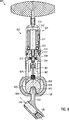
Vorrichtung zum Vorspannen einer Konusverbindung (103, 806) zwischen einem ersten Teil (101, 102) und einem zweiten Teil (102, 803) eines Implantats (100), umfassend: ein Sollbruchelement (200, 807), das mit dem ersten Teil (101, 102) verbindbar und dafür ausgelegt ist, bei einer vorgegebenen Bruchkraft, die in einer Richtung vom ersten Teil (101, 102) auf den zweiten Teil (102, 803) zu wirkt, zu brechen; und einen Vorspannmechanismus (300, 801) zum Ausüben einer Kraft auf das mit dem ersten Teil (101, 102) verbundene Sollbruchelement (200, 807), die in der Richtung vom ersten Teil (101, 102) auf den zweiten Teil (102, 807) zu wirkt, und zum Ausüben einer Gegenkraft auf den zweiten Teil (102, 807), die in einer zur Richtung vom ersten Teil (101, 102) auf den zweiten Teil (102, 803) zu entgegengesetzte Richtung wirkt, wobei der Vorspannmechanismus (300, 801) zum Bereitstellen der Bruchkraft ausgelegt ist.A device for biasing a tapered connection (103, 806) between a first part (101, 102) and a second part (102, 803) of an implant (100), comprising: a predetermined breaking element (200, 807) connected to the first part ( 101, 102) and adapted to break at a predetermined breaking force acting in a direction from the first part (101, 102) to the second part (102, 803); and a biasing mechanism (300, 801) for exerting a force on the predetermined breaking element (200, 807) connected to the first part (101, 102), which in the direction from the first part (101, 102) to the second part (102, 807), and for applying a counterforce to the second part (102, 807) acting in a direction opposite to the direction from the first part (101, 102) to the second part (102, 803), the biasing mechanism (300, 801) is designed to provide the breaking force.
Description
Die Erfindung bezieht sich auf eine Vorrichtung zum Vorspannen einer Konusverbindung zwischen einem ersten Teil und einem zweiten Teil eines Implantats.The invention relates to a device for biasing a cone connection between a first part and a second part of an implant.
In der
In der
Ein weiteres Hüftimplantat, in dem Konusverbindungen zum Verbinden von Teilen des Hüftimplantats verwendet werden, wird in der
Zur Herstellung einer Konusverbindung zwischen zwei Teilen eines Implantats wird ein männlicher Konus (ein Vorsprung, der eine zumindest teilweise konische Oberfläche aufweist) in einen weiblichen Konus (eine Vertiefung, die eine zumindest teilweise konische Oberfläche aufweist) eingesetzt, wobei die Kegelwinkel der beiden Konen typischerweise im Wesentlichen gleich sind. Dabei entsteht ein Reibschluss zwischen dem männlichen Konus und dem weiblichen Konus, durch den die beiden Teile miteinander verbunden werden.To create a cone connection between two parts of an implant, a male cone (a projection having an at least partially conical surface) is inserted into a female cone (a recess having an at least partially conical surface), the cone angles of the two cones typically are essentially the same. This results in a frictional connection between the male cone and the female cone, through which the two parts are joined together.
Durch eine feste Verbindung der Konen wird die Stabilität des Implantats verbessert. Insbesondere kann eine feste Verbindung zwischen den Konen dabei helfen, Relativbewegungen zwischen den Teilen des Implantats zu verhindern oder zumindest zu verringern, wodurch die langfristige Haltbarkeit des Implantats verbessert wird. Außerdem kann das Eindringen korrosiver Substanzen aus dem Körper des Patienten zwischen die Konen verhindert oder zumindest verringert werden, was zur Vermeidung einer Korrosion der Konen beitragen kann.A firm connection of the cones improves the stability of the implant. In particular, a tight connection between the cones may help to prevent or at least reduce relative movements between the parts of the implant, thereby improving the long-term durability of the implant. In addition, the penetration of corrosive substances from the body of the patient between the cones can be prevented or at least reduced, which can contribute to the prevention of corrosion of the cones.
Zur Herstellung einer festen Verbindung zwischen den Konen wird die Konusverbindung nach dem Einsetzen des männlichen Konus in den weiblichen Konus vorgespannt. Zu diesem Zweck werden Vorrichtungen mit einem Gewinde und einem Drehmomentbegrenzer verwendet, in denen durch den Drehmomentbegrenzer ein Drehmoment, das auf das Gewinde wirkt, festgelegt wird. Das Drehmoment wird durch das Gewinde in eine lineare Kraft umgewandelt, die auf die Konen übertragen wird, um sie ineinander zu pressen. Dadurch wird der Reibschluss zwischen den Konen verbessert.To establish a tight connection between the cones, the cone connection is preloaded after inserting the male cone into the female cone. For this purpose, devices with a thread and a torque limiter are used in which a torque acting on the thread is determined by the torque limiter. The torque is converted by the thread into a linear force which is transmitted to the cones to press them into each other. This improves the frictional engagement between the cones.
In derartigen Vorrichtungen zum Vorspannen einer Konusverbindung können jedoch Probleme mit der Kraftübertragung auftreten. Die bei vorgegebenem Drehmoment ausgeübte lineare Kraft kann sich zum Einen durch Reibung im Gewinde, zum Anderen durch Verkippung in Form eines Biegemomentes verringern. Bei der Aufbereitung der Vorrichtungen in Kliniken nach der Operation kann es zudem zu einer Verschlechterung kommen, insbesondere durch die beim Sterilisieren eingesetzten Temperaturen und/oder Chemikalien. Dadurch wird die Reibung weiter erhöht.However, in such devices for biasing a cone joint, problems with power transmission can occur. The linear force exerted for a given torque can be reduced on the one hand by friction in the thread, on the other hand by tilting in the form of a bending moment. In the treatment of devices in clinics after surgery, it can also lead to deterioration, in particular by the temperatures and / or chemicals used in sterilization. This further increases the friction.
Ein Nachteil von Vorrichtungen zum Vorspannen einer Konusverbindung zwischen zwei Teilen eines Implantats nach dem Stand der Technik ist deshalb, dass das Vorspannen mit einer vorgegebenen Kraft nur mit einer relativ großen Ungenauigkeit von ca. ± 20% möglich ist.A disadvantage of devices for biasing a cone connection between two parts of a prior art implant is, therefore, that preloading with a given force is possible only with a relatively large inaccuracy of about ± 20%.
Eine Aufgabe der Erfindung ist, eine Vorrichtung zum Vorspannen einer Konusverbindung zwischen einem ersten Teil und einem zweiten Teil eines Implantats bereitzustellen, mit der ein genaueres Ausüben einer vorgegebenen Kraft zwischen dem ersten Teil und dem zweiten Teil des Implantats erreicht werden kann.An object of the invention is to provide a device for biasing a cone connection between a first part and a second part of an implant, with which a more precise exertion of a predetermined force between the first part and the second part of the implant can be achieved.
Eine weitere Aufgabe der Erfindung ist, die beim Vorspannen nach der herkömmlichen Methode unweigerlich auftretenden Biegemomente zu reduzieren.Another object of the invention is to reduce the bending moments inevitably occurring during pretensioning according to the conventional method.
Erfindungsgemäß werden die Aufgaben zumindest teilweise durch eine Vorrichtung zum Vorspannen einer Konusverbindung zwischen einem ersten Teil und einem zweiten Teil eines Implantats gelöst, die ein Sollbruchelement und einen Vorspannmechanismus umfasst. Das Sollbruchelement ist mit dem ersten Teil verbindbar und dafür ausgelegt, bei einer vorgegebenen Bruchkraft, die in einer Richtung vom ersten Teil auf den zweiten Teil zu wirkt, zu brechen. Der Vorspannmechanismus ist zum Ausüben einer Kraft auf das mit dem ersten Teil verbundene Sollbruchelement geeignet. Die Kraft wirkt in der Richtung vom ersten Teil auf den zweiten Teil zu. Insbesondere kann in Ausführungsformen die Kraft streng axial in der Richtung vom ersten Teil auf den zweiten Teil zu wirken. Der Vorspannmechanismus ist außerdem zum Ausüben einer Gegenkraft auf den zweiten Teil geeignet, die in einer Richtung wirkt, die zu der Richtung vom ersten Teil auf den zweiten Teil zu entgegengesetzt ist. Der Vorspannmechanismus ist zum Bereitstellen der Bruchkraft, die in Ausführungsformen insbesondere eine axiale Bruchkraft sein kann, ausgelegt.According to the invention, the objects are at least partially solved by a device for biasing a cone connection between a first part and a second part of an implant, which comprises a predetermined breaking element and a biasing mechanism. The predetermined breaking element is connectable to the first part and adapted to break at a predetermined breaking force acting in a direction from the first part to the second part. The biasing mechanism is for applying a force to that with the first part connected predetermined breaking element suitable. The force acts in the direction from the first part to the second part. In particular, in embodiments, the force may be strictly axial in the direction from the first part to the second part. The biasing mechanism is also suitable for applying a counterforce to the second part which acts in a direction opposite to the direction from the first part to the second part. The biasing mechanism is designed to provide the breaking force, which in particular may be an axial breaking force in embodiments.
Zum Vorspannen der Konusverbindung kann das Sollbruchelement mit dem ersten Teil verbunden und durch den Vorspannmechanismus eine Kraft auf das Sollbruchelement und eine Gegenkraft auf den zweiten Teil des Implantats ausgeübt werden. Durch die Kraft und die Gegenkräfte werden die beiden Teile des Implantats zusammengepresst, wodurch der männliche Konus der Konusverbindung in den weiblichen Konus gedrückt und die Konusverbindung vorgespannt wird. Die ausgeübte Kraft kann solange erhöht werden, bis die Bruchkraft überschritten wird und das Sollbruchelement bricht.For biasing the cone connection, the predetermined breaking element can be connected to the first part and a force on the predetermined breaking element and a counterforce on the second part of the implant can be exerted by the biasing mechanism. Force and opposing forces compress the two parts of the implant, thereby forcing the male cone of the cone connection into the female cone and biasing the cone connection. The applied force can be increased until the breaking force is exceeded and the predetermined breaking element breaks.
Durch das Sollbruchelement wird somit die Kraft, mit der die Teile des Implantats zusammengepresst werden, auf die Bruchkraft begrenzt. Der Wert der Bruchkraft, bei der das Sollbruchelement bricht, hängt von dem Material, aus dem das Sollbruchelement besteht, und von der Formgebung des Sollbruchelements ab.By the predetermined breaking element thus the force with which the parts of the implant are pressed together, limited to the breaking force. The value of the breaking force at which the predetermined breaking element breaks, depends on the material of which the predetermined breaking element consists, and on the shape of the predetermined breaking element.
Durch die Wahl des Materials des Sollbruchelements und die Formgebung des Sollbruchelements kann die Kraft, mit der die beiden Teile des Implantats beim Vorspannen der Konusverbindung zusammengepresst werden, mit relativ guter Genauigkeit festgelegt werden. Reibung, die im Vorspannmechanismus auftritt, hat keine oder nur sehr geringe Auswirkungen auf die Kraft, mit der die Teile des Implantats zusammengepresst werden, da der Vorspannmechanismus im Kraftfluss stromaufwärts des Sollbruchelements liegt.By choosing the material of the predetermined breaking element and the shape of the predetermined breaking element, the force with which the two parts of the implant are pressed together during pretensioning of the cone connection can be determined with relatively good accuracy. Friction that occurs in the biasing mechanism has little or no effect on the force with which the parts of the implant are compressed because the biasing mechanism is located in the force flow upstream of the predetermined breaking element.
Zudem kann die Kraft, mit der die beiden Teile des Implantats beim Vorspannen der Konusverbindung zusammengepresst werden, durch die Wahl des Materials des Sollbruchelements und die Formgebung des Sollbruchelements in weiten Bereichen auf einfachste Weise den speziellen unterschiedlichen Anforderungen verschiedenster Konusverbindungen und damit Lastsituationen angepasst werden. Der Vorspannmechanismus selbst muss hierfür nicht angepasst werden, da er nur die zum Erreichen der gewünschten Vorspannkraft benötigte Kraft zur Verfügung stellt. Die Höhe dieser Kraft wird allein durch die genannten materialspezifischen und geometrischen Eigenschaften des Sollbruchelements bestimmt.In addition, the force with which the two parts of the implant are compressed when preloading the cone connection, by the choice of the material of the predetermined breaking element and the shape of the predetermined breaking element in a wide range in the simplest way the special different requirements of different cone connections and thus load situations can be adjusted. The biasing mechanism itself does not need to be adjusted for this because it provides only the force needed to achieve the desired preload force. The amount of this force is determined solely by the specified material-specific and geometric properties of the predetermined breaking element.
Aufgrund der streng axialen Kraftführung und des Einsatzes eines Getriebes mit Untersetzung können in manchen Ausführungsformen die zum Erreichen der Vorspannkraft nötigen Hebelverhältnisse deutlich reduziert werden. Die während des Vorspannens auftretenden Biegemomente werden hiermit sehr effektiv verringert.Due to the strictly axial force guidance and the use of a transmission with reduction in some embodiments, the leverage required to achieve the biasing force can be significantly reduced. The bending moments occurring during pre-stressing are hereby very effectively reduced.
In manchen Ausführungsformen umfasst das Sollbruchelement ein Befestigungselement an einem ersten Ende des Sollbruchelements, einen Kopf an einem zweiten Ende des Sollbruchelements und einen Bruchabschnitt, der sich zwischen dem Befestigungselement und dem Kopf befindet. Der Bruchabschnitt ist dafür ausgelegt, bei der Bruchkraft zu brechen, wobei die Bruchkraft eine Zugkraft ist, die axial in einer Längsrichtung des Bruchabschnitts wirkt.In some embodiments, the predetermined breaking element comprises a fastener at a first end of the break element, a head at a second end of the break element, and a fracture section located between the fastener and the head. The breaking portion is designed to break at the breaking force, the breaking force being a tensile force acting axially in a longitudinal direction of the breaking portion.
Das Befestigungselement kann zum Verbinden des Sollbruchelements mit dem ersten Teil des Implantats verwendet werden und der Kopf kann in den Vorspannmechanismus eingesetzt werden, um die Kraft auf das Sollbruchelement auszuüben, wobei der Vorspannmechanismus am Kopf zieht.The fastener may be used to connect the frangible member to the first part of the implant, and the head may be inserted into the biasing mechanism to apply the force to the frangible member, the biasing mechanism pulling on the head.
In manchen Ausführungsformen umfasst die Vorrichtung eine erste Kraftübertragungseinheit zum Übertragen der vom Vorspannmechanismus ausgeübten Gegenkraft auf den zweiten Teil des Implantats. Die erste Kraftübertragungseinheit kann einen Prothesen-Ein/Ausschläger umfassen.In some embodiments, the device includes a first force transfer unit for transferring the counterforce exerted by the biasing mechanism to the second part of the implant. The first power transmission unit may comprise a prosthesis on / knockout.
In manchen Ausführungsformen kann die Vorrichtung eine zweite Kraftübertragungseinheit zum Übertragen der vom Vorspannmechanismus ausgeübten Kraft umfassen. Die zweite Kraftübertragungseinheit ist lösbar derart am Sollbruchelement und am zweiten Teil des Implantats befestigbar, dass das Sollbruchelement durch die zweite Kraftübertragungseinheit mit dem ersten Teil des Implantats verbunden ist.In some embodiments, the apparatus may include a second power transmission unit for transmitting the force exerted by the biasing mechanism. The second power transmission unit is detachably fastened to the predetermined breaking element and to the second part of the implant such that the predetermined breaking element is connected to the first part of the implant by the second power transmission unit.
Durch die erste und die zweite Kraftübertragungseinheit können sich der Vorspannmechanismus und das Sollbruchelement beim Vorspannen der Konusverbindung in einem Abstand zum Implantat befinden. Da sich das Implantat beim Vorspannen der Konusverbindung typischerweise bereits im Körper des Patienten befindet, kann so eine günstigere Arbeitsposition für den Operateur, der die Vorrichtung benutzt, erreicht werden. In Ausführungsformen, in denen die erste Kraftübertragungseinheit einen Prothesen-Ein/Ausschläger umfasst, kann die erste Kraftübertragungseinheit außer zum Vorspannen der Konusverbindung auch für andere Zwecke verwendet werden, beispielsweise um die Konusverbindung wieder zu lösen, wenn sich herausstellt, dass die Anordnung des ersten Teils und des zweiten Teils des Implantats relativ zueinander nicht optimal ist. Durch die Verwendung der zweiten Kraftübertragungseinheit kann auch die bei einem bestimmten Abstand zwischen dem Vorspannmechanismus und dem ersten Teil des Implantats erforderliche Länge des Sollbruchelements verringert werden. Da das Sollbruchelement beim Vorspannen der Konusverbindung zerstört wird und somit nur ein einziges Mal verwendet werden kann, kann dadurch der Materialverbrauch verringert werden.By the first and the second power transmission unit, the biasing mechanism and the predetermined breaking element may be at a distance from the implant when biasing the cone connection. Since the implant is typically already in the body of the patient when preloading the cone connection, a more favorable working position for the surgeon using the device can be achieved. In embodiments in which the first power transmission unit comprises a prosthetic in / out impactor, the first power transmission unit may be used for other purposes besides biasing the conical connection, for example, to re-release the conical connection, if it turns out that the Arrangement of the first part and the second part of the implant relative to each other is not optimal. By using the second power transmission unit, it is also possible to reduce the length of the predetermined breaking element required at a specific distance between the pretensioning mechanism and the first part of the implant. Since the predetermined breaking element is destroyed when biasing the cone connection and thus can be used only once, thereby the material consumption can be reduced.
In manchen Ausführungsformen umfasst die zweite Kraftübertragungseinheit einen Stab und eine Hülsenmutter. Der Stab weist ein ersten Außengewinde an einem ersten Ende des Stabs und ein zweites Außengewinde an einem zweiten Ende des Stabs auf. Das erste Außengewinde ist zum Einschrauben in eine Gewindebohrung im ersten Teil des Implantats, die sich entlang einer Achse eines im ersten Teil des Implantats vorgesehenen Konus erstreckt, geeignet. Die Hülsenmutter umfasst ein Innengewinde, in das das zweite Außengewinde einschraubbar ist und ein Befestigungselement, das zum Verbinden mit dem Sollbruchelement geeignet ist und sich auf einer dem ersten Innengewinde gegenüberliegenden Seite der Hülsenmutter befindet.In some embodiments, the second power transmission unit includes a rod and a sleeve nut. The rod has a first external thread at a first end of the rod and a second external thread at a second end of the rod. The first external thread is suitable for screwing into a threaded bore in the first part of the implant, which extends along an axis of a cone provided in the first part of the implant. The sleeve nut comprises an internal thread into which the second external thread can be screwed and a fastening element which is suitable for connection to the predetermined breaking element and which is located on a side of the sleeve nut opposite the first internal thread.
Beim Einsetzen des Implantats in den Körper des Patienten kann der Stab zur Führung des zweiten Teils des Implantats verwendet werden, wenn der zweite Teil auf den ersten Teil aufgesetzt wird. Der zweite Teil des Implantats kann dabei eine Längsbohrung aufweisen, die sich beispielsweise entlang der Achse des Konus des zweiten Teils des Implantats erstreckt. Der Stab kann durch die Längsbohrung des zweiten Teils des Implantats geführt werden, so dass der Konus des zweiten Teils des Implantats zentriert auf den Konus im ersten Teil des Implantats, dessen Achse mit der Achse des Stabs zusammenfallen kann, aufgesetzt wird. Anschließend kann die Hülsenmutter auf den Stab geschraubt werden, um die Konusverbindung vorzuspannen.When inserting the implant in the body of the patient, the rod can be used to guide the second part of the implant when the second part is placed on the first part. The second part of the implant can have a longitudinal bore extending, for example, along the axis of the cone of the second part of the implant. The rod may be passed through the longitudinal bore of the second part of the implant so that the cone of the second part of the implant is centered on the cone in the first part of the implant, the axis of which may coincide with the axis of the rod. Subsequently, the sleeve nut can be screwed onto the rod to bias the cone connection.
In manchen Ausführungsformen weist das Sollbruchelement ein Befestigungselement auf, das lösbar mit dem Befestigungselement der Hülsenmutter verbindbar ist. Dadurch kann ein Teil des gebrochenen Sollbruchelements nach dem Vorspannen der Konusverbindung durch Lösen der Befestigungselemente von der Hülsenmutter entfernt werden, so dass die Hülsenmutter weiter verwendet werden kann.In some embodiments, the predetermined breaking element has a fastening element which is detachably connectable to the fastening element of the sleeve nut. Thereby, a part of the broken predetermined breaking element after biasing the cone connection can be removed by loosening the fastening elements of the sleeve nut, so that the sleeve nut can be used further.
In manchen Ausführungsformen weist die erste Kraftübertragungseinheit eine Längsbohrung auf, in die zumindest ein Teil der zweiten Kraftübertragungseinheit einsetzbar ist. Dadurch kann erreicht werden, dass beim Vorspannen der Konusverbindung kein Drehmoment auf das Implantat ausgeübt wird, wodurch die Wahrscheinlichkeit eines Verkantens der Konen verringert wird.In some embodiments, the first power transmission unit has a longitudinal bore into which at least a part of the second power transmission unit can be inserted. It can thereby be achieved that no torque is exerted on the implant when preloading the cone connection, whereby the likelihood of tilting of the cones is reduced.
In manchen Ausführungsformen umfasst der Vorspannmechanismus eine Aufnahme für das Sollbruchelement, einen Gegenhalter mit einer Auflagefläche und eine Einrichtung zum linearen Bewegen der Aufnahme für das Sollbruchelement von einer ersten Stellung zu einer zweiten Stellung, wobei die Aufnahme in der zweiten Stellung weiter von der Auflagefläche entfernt ist als in der ersten Stellung.In some embodiments, the biasing mechanism includes a susceptor for the breakaway member, an anvil having a support surface, and means for linearly moving the susceptor for the breakaway member from a first position to a second position, wherein the receptacle is farther from the support surface in the second position as in the first position.
Durch die Aufnahme für das Sollbruchelement kann die Kraft, die vom Vorspannmechanismus ausgeübt wird, auf das Sollbruchelement übertragen werden, und die Gegenkraft kann durch den Gegenhalter ausgeübt werden. Durch das lineare Bewegen der Aufnahme für den Teil des Sollbruchelements kann die Kraft auf das Sollbruchelement ausgeübt werden, ohne dass ein Drehmoment ausgeübt wird, durch das der erste Teil und der zweite Teil des Implantats gegeneinander verdreht werden könnten.By receiving the frangible element, the force exerted by the biasing mechanism can be transmitted to the frangible element, and the counterforce can be exerted by the anvil. The linear movement of the receptacle for the part of the predetermined breaking element, the force can be exerted on the predetermined breaking element, without a torque is applied, by which the first part and the second part of the implant could be rotated against each other.
In manchen Ausführungsformen ist eine erste Kraftübertragungseinheit mit den oben beschriebenen Merkmalen vorhanden und die Auflagefläche des Gegenhalters ist zum Auflegen auf einer Fläche der ersten Kraftübertragungseinheit, die sich auf einer vom Implantat abgewandten Seite der ersten Kraftübertragungseinheit befindet, geeignet. Der Gegenhalter umfasst ein oder mehrere Elemente, die dafür geeignet sind, eine Drehung des Gegenhalters relativ zur ersten Kraftübertragungseinheit zu verhindern, wenn die Auflagefläche des Gegenhalters auf der Fläche der ersten Kraftübertragungseinheit aufliegt. In manchen Ausführungsformen können die Elemente zum Verhindern der Drehung des Gegenhalters relativ zur ersten Kraftübertragungseinheit zwei Vorsprünge umfassen, zwischen die ein Teil der ersten Kraftübertragungseinheit, der die Fläche umfasst, einsetzbar ist. Dadurch kann verhindert werden, dass sich der Gegenhalter beim Vorspannen der Konusverbindung relativ zur ersten Kraftübertragungseinheit verdreht.In some embodiments, a first power transmission unit having the features described above is present and the support surface of the backstop is adapted for placement on a surface of the first power transmission unit located on a side of the first power transmission unit facing away from the implant. The anvil includes one or more elements adapted to prevent rotation of the anvil relative to the first power transmission unit when the support surface of the anvil rests on the surface of the first power transmission unit. In some embodiments, the elements for preventing rotation of the anvil relative to the first power transmission unit may include two protrusions, between which a portion of the first power transmission unit comprising the surface may be inserted. As a result, it is possible to prevent the counterholder from twisting relative to the first power transmission unit during pretensioning of the cone connection.
In manchen Ausführungsformen weist die Auflagefläche des Gegenhalters eine sphärische Krümmung auf und ist zur Auflage auf einer Oberfläche einer Gelenkkugel, die den zweiten Teil des Implantats bildet, ausgelegt. Die Vorrichtung kann außerdem ein Halteelement umfassen, das lösbar mit dem Sollbruchelement verbindbar ist und zum Ansetzen an dem ersten Teil des Implantats ausgelegt ist. Eine Vorrichtung mit derartigen Merkmalen ist insbesondere zum Vorspannen einer Konusverbindung zwischen einer Gelenkkugel und anderen Teilen eines Implantats geeignet.In some embodiments, the support surface of the anvil has a spherical curvature and is designed to rest on a surface of a joint ball that forms the second part of the implant. The device may further comprise a holding element, which is detachably connectable to the predetermined breaking element and is designed for attachment to the first part of the implant. A device with such features is particularly suitable for biasing a cone connection between a joint ball and other parts of an implant.
In manchen Ausführungsformen weist das Sollbruchelement die oben beschriebenen Merkmale auf. Die Aufnahme für das Sollbruchelement weist einen ersten und einen zweiten Wandbereich auf, die sich auf zwei einander gegenüberliegenden Seiten der Aufnahme befinden. Der erste Wandbereich und der zweite Wandbereich weisen jeweils einen vorspringenden Abschnitt auf. Der Kopf des Sollbruchelements ist auf einer der Auflagefläche abgewandten Seite der vorspringenden Abschnitte zwischen dem ersten und dem zweiten Wandbereich einsetzbar. Die vorspringenden Abschnitte bilden einen Schlitz, in den ein Teil des Sollbruchelements einführbar ist. Die Breite des Schlitzes ist kleiner als ein Durchmesser des Kopfs des Sollbruchelements.In some embodiments, the predetermined breaking element is that described above Features on. The receptacle for the predetermined breaking element has a first and a second wall portion, which are located on two opposite sides of the receptacle. The first wall portion and the second wall portion each have a projecting portion. The head of the predetermined breaking element can be inserted on a side of the projecting sections facing away from the supporting surface between the first and the second wall region. The projecting portions form a slot into which a part of the predetermined breaking element is insertable. The width of the slot is smaller than a diameter of the head of the predetermined breaking element.
Durch diese Ausgestaltung der Aufnahme kann der Kopf des Sollbruchelements beim Vorspannen der Konusverbindung von den vorspringenden Abschnitten der Wandbereiche festgehalten werden, und die Kraft kann auf das Sollbruchelement ausgeübt werden, indem die Aufnahme von der ersten Stellung zur zweiten Stellung bewegt wird. Dadurch kann eine Zugkraft auf den mit dem Sollbruchelement verbundenen ersten Teil des Implantats ausgeübt werden. Der Kopf des Sollbruchelements und ein Teil des Sollbruchelements, der sich an den Kopf anschließt, können in die Aufnahme eingeführt werden, indem der Kopf zwischen den ersten und den zweiten Wandbereich gebracht wird, wobei sich der Teil des Sollbruchelements, der sich an den Kopf anschließt, im Schlitz befindet.As a result of this design of the receptacle, the head of the predetermined breaking element can be retained by the protruding sections of the wall regions during pretensioning of the cone connection, and the force can be exerted on the predetermined breaking element by moving the receptacle from the first position to the second position. As a result, a tensile force can be exerted on the first part of the implant connected to the predetermined breaking element. The head of the predetermined breaking element and a part of the predetermined breaking element, which adjoins the head, can be introduced into the receptacle by bringing the head between the first and the second wall area, wherein the part of the predetermined breaking element, which adjoins the head , located in the slot.
In manchen Ausführungsformen weist die Aufnahme einen dritten Wandbereich auf, der den ersten und zweiten Wandbereich verbindet. Gegenüber dem dritten Wandabschnitt befindet sich eine Öffnung, durch die zumindest der Kopf des Sollbruchelements in die Aufnahme einsetzbar ist, wenn sich die Aufnahme in der ersten Stellung befindet. Der Gegenhalter umfasst ein Blockierelement, das dafür ausgelegt ist, ein Hindurchtreten des Kopfs des Sollbruchelements durch die Öffnung zu verhindern, wenn sich die Aufnahme in der zweiten Stellung befindet.In some embodiments, the receptacle has a third wall portion connecting the first and second wall portions. Opposite the third wall portion is an opening through which at least the head of the predetermined breaking element can be inserted into the receptacle when the receptacle is in the first position. The anvil includes a blocking member adapted to prevent the head of the breakaway member from passing through the opening when the receptacle is in the second position.
Dadurch kann das Sollbruchelement vor dem Vorspannen der Konusverbindung in den Vorspannmechanismus eingesetzt werden, während sich die Aufnahme in der ersten Stellung befindet. Nach dem Vorspannen der Konusverbindung befindet sich die Aufnahme typischerweise in der zweiten Stellung. Durch das Blockierelement werden dann der Kopf des Sollbruchelements und der noch mit dem Kopf verbundene Teil des gebrochenen Sollbruchelements im Vorspannmechanismus festgehalten, wodurch verhindert wird, dass der Teil des Sollbruchelements verloren geht.Thereby, the predetermined breaking element can be used before biasing the cone connection in the biasing mechanism, while the receptacle is in the first position. After preloading the cone connection, the receptacle is typically in the second position. By the blocking element of the head of the predetermined breaking element and the still connected to the head part of the broken predetermined breaking element are then held in the biasing mechanism, thereby preventing the part of the predetermined breaking element is lost.
In manchen Ausführungsformen umfasst die Einrichtung zum linearen Bewegen der Aufnahme eine Gewindespindel. Die Vorrichtung kann außerdem einen Handgriff zum Drehen einer Gewindemutter der Gewindespindel umfassen.In some embodiments, the means for linearly moving the receptacle comprises a threaded spindle. The device may also include a handle for rotating a threaded nut of the threaded spindle.
In manchen Ausführungsformen umfasst die Vorrichtung eine Ratschenvorrichtung, die dafür geeignet ist, eine Drehung einer Gewindemutter der Gewindespindel relativ zu der Gewindespindel in einer Richtung, die einer Bewegung der Aufnahme für das Sollbruchelement von der ersten Stellung zu der zweiten Stellung entspricht, zuzulassen und eine Drehung in der entgegengesetzten Richtung zu blockieren. Dadurch kann ein unerwünschtes Zurückdrehen der Gewindemutter, das insbesondere dann auftreten kann, wenn der Benutzer am Handgriff umgreift, verhindert werden.In some embodiments, the apparatus includes a ratchet device adapted to permit rotation of a threaded nut of the lead screw relative to the lead screw in a direction corresponding to movement of the susceptor for the frangible element from the first position to the second position and rotation to block in the opposite direction. As a result, an undesired turning back of the threaded nut, which can occur in particular when the user engages around the handle, be prevented.
Im Folgenden werden Ausführungsformen der Erfindung mit Bezug auf die Figuren beschrieben.Hereinafter, embodiments of the invention will be described with reference to the drawings.
Der Schaft
Im Schaft
Nach dem Verbinden des Schafts
Zum Bereitstellen der Konusverbindung
Durch die Kraft und die Gegenkraft werden der Schaft
Zum Vorspannen der Konusverbindung
Die Vorrichtung zum Vorspannen einer Konusverbindung umfasst ein Sollbruchelement
Das Sollbruchelement
Zwischen dem Außengewinde
Der Bruchabschnitt
In einer Ausführungsform kann das Sollbruchelement
In anderen Ausführungsformen können andere Materialien, andere Abmessungen und andere Querschnittsgeometrien des Bruchabschnitts
Der Durchmesser
Zwischen dem Bruchabschnitt
Auf einer dem zweiten Ende
In
In dem Spannungs-Dehnungs-Diagramm
Bei kleinen Längenänderungen steigt die zum Erreichen der Längenänderung erforderliche Kraft mit zunehmender Längenänderung an, bis ein Maximum der Kraft erreicht ist, das der Bruchkraft des Sollbruchelements
In den
Der Vorspannmechanismus
Die lineare Bewegung der Aufnahme
Der Gegenhalter
Der Gegenhalter
Die Einrichtung
Durch die nicht-kreisförmige Form der Öffnung
Die Einrichtung
Zwischen der Gewindemutter
Die Einrichtung
In manchen Ausführungsformen kann zwischen dem Gegenhalter
Um eine lineare Bewegung der Griffhülse
Der Vorspannmechanismus
In den
Die Aufnahme
Die Nasen, Vorsprünge und/oder Federelemente können relativ klein dimensioniert sein, insbesondere können sie eine maximale Abmessung haben, die kleiner oder gleich einer Breite der vorspringenden Abschnitte in einer Richtung parallel zur Längsachse
Ein Abstand
Der Kopf
Wenn sich der Kopf
Zwischen dem ersten Wandabschnitt
Die Aufnahme
Wenn sich die Aufnahme
Wenn sich die Aufnahme
Am Gegenhalter
Die Vorrichtung zum Vorspannen der Konusverbindung umfasst ferner einen Prothesen-Ein/Ausschläger
Der Prothesen-Ein/Ausschläger
Die Vorrichtung zum Vorspannen der Konusverbindung umfasst ferner eine zweite Kraftübertragungseinheit, die einen Stab
Der Stab
Die Hülsenmutter
Die Hülsenmutter
Im Folgenden wird das Vorspannen der Konusverbindung
Beim Implantieren des Hüftimplantats
Danach wird das Halsteil
Danach kann der Prothesen-Ein/Ausschläger
Danach wird die Hülsenmutter
Danach kann das Sollbruchelement
Danach kann der Vorspannmechanismus
Der Kopf
Danach kann durch Drehen am Handgriff
Wenn vom Vorspannmechanismus
Während die Aufnahme
Der Vorspannmechanismus
Während die Aufnahme
Anschließend kann die Vorrichtung zum Vorspannen der Konusverbindung vom Hüftimplantat
Die Erfindung ist nicht auf Ausführungsformen beschränkt, in denen der Vorspannmechanismus, wie oben beschrieben, einen durch einen Handgriff betätigbaren Gewindetrieb umfasst. In anderen Ausführungsformen kann stattdessen ein durch einen Elektromotor betriebener Gewindetrieb und/oder eine hydraulische Zugvorrichtung verwendet werden.The invention is not limited to embodiments in which the biasing mechanism, as described above, comprises a manually operable screw drive. In other embodiments, an electric motor operated screw drive and / or a hydraulic pulling device may be used instead.
Die Erfindung ist nicht auf Ausführungsformen beschränkt, in denen ein Prothesen-Ein/Ausschläger als Kraftübertragungseinheit zum Übertragen der vom Vorspannmechanismus ausgeübten Gegenkraft auf das Halsteil
Die Erfindung ist nicht auf Ausführungsformen beschränkt, in denen, wie oben beschrieben, eine Kraftübertragungseinheit verwendet wird, die den Stab
In weiteren Ausführungsformen kann zwischen dem Schaft
In weiteren Ausführungsformen kann eine Vorrichtung zum Vorspannen einer Konusverbindung, die ein Sollbruchelement und einen Vorspannmechanismus ähnlich dem oben beschriebenen Sollbruchelement
Solche Ausführungsformen werden im Folgenden mit Bezug auf
Die Vorrichtung
Das Sollbruchelement
Der Vorspannmechanismus
Der Gegenhalter
Das Halteelement
Das Sollbruchelement
Zum Vorspannen der Konusverbindung
Durch die Bruchkraft des Sollbruchelements
Die exakte zur Montage der Gelenkkugel
Alternativ können Halteelemente zum Vorspannen einer Konusverbindung zwischen dem Halsteil
Nach dem Stand der Technik wird die Montagekraft der Gelenkkugel per Hammerschlag aufgebracht. Im Vergleich mit dem Stand der Technik ermöglicht die Vorrichtung
Die Erfindung ist nicht auf Ausführungsformen beschränkt, in denen eine Konusverbindung zwischen Teilen eines Hüftimplantats vorgespannt wird. Eine Vorrichtung zum Vorspannen einer Konusverbindung ähnlich der oben beschriebenen Vorrichtung kann auch zum Vorspannen von Konusverbindungen in anderen Implantaten wie beispielsweise Kniegelenksprothesen verwendet werden.The invention is not limited to embodiments in which a cone connection is biased between parts of a hip implant. A device for biasing a Tapered connection similar to the device described above may also be used to bias cone connections in other implants such as knee joint prostheses.
Die Erfindung ist nicht auf Ausführungsformen beschränkt, in denen eine Konusverbindung zwischen Teilen eines Implantats vorgespannt wird. Eine Vorrichtung zum Vorspannen einer Konusverbindung ähnlich der oben beschriebenen Vorrichtung kann zum Vorspannen von Konusverbindungen jeglicher Art verwendet werden.The invention is not limited to embodiments in which a cone connection is biased between parts of an implant. A device for biasing a cone connection similar to the device described above may be used to bias cone connections of any type.
ZITATE ENTHALTEN IN DER BESCHREIBUNG QUOTES INCLUDE IN THE DESCRIPTION
Diese Liste der vom Anmelder aufgeführten Dokumente wurde automatisiert erzeugt und ist ausschließlich zur besseren Information des Lesers aufgenommen. Die Liste ist nicht Bestandteil der deutschen Patent- bzw. Gebrauchsmusteranmeldung. Das DPMA übernimmt keinerlei Haftung für etwaige Fehler oder Auslassungen.This list of the documents listed by the applicant has been generated automatically and is included solely for the better information of the reader. The list is not part of the German patent or utility model application. The DPMA assumes no liability for any errors or omissions.
Zitierte PatentliteraturCited patent literature
- DE 29506036 U1 [0002] DE 29506036 U1 [0002]
- DE 4320086 C3 [0003] DE 4320086 C3 [0003]
- DE 202006014950 U1 [0004] DE 202006014950 U1 [0004]
Zitierte Nicht-PatentliteraturCited non-patent literature
- DIN EN 10088 [0057] DIN EN 10088 [0057]
Claims (18)
Priority Applications (1)
| Application Number | Priority Date | Filing Date | Title |
|---|---|---|---|
| DE202012102017U DE202012102017U1 (en) | 2012-06-01 | 2012-06-01 | Device for biasing a cone connection |
Applications Claiming Priority (1)
| Application Number | Priority Date | Filing Date | Title |
|---|---|---|---|
| DE202012102017U DE202012102017U1 (en) | 2012-06-01 | 2012-06-01 | Device for biasing a cone connection |
Publications (1)
| Publication Number | Publication Date |
|---|---|
| DE202012102017U1 true DE202012102017U1 (en) | 2013-09-03 |
Family
ID=49290438
Family Applications (1)
| Application Number | Title | Priority Date | Filing Date |
|---|---|---|---|
| DE202012102017U Expired - Lifetime DE202012102017U1 (en) | 2012-06-01 | 2012-06-01 | Device for biasing a cone connection |
Country Status (1)
| Country | Link |
|---|---|
| DE (1) | DE202012102017U1 (en) |
Cited By (10)
| Publication number | Priority date | Publication date | Assignee | Title |
|---|---|---|---|---|
| EP2724693A1 (en) * | 2012-10-18 | 2014-04-30 | DePuy Synthes Products, LLC | Orthopaedic prosthesis assembly tool |
| US9095452B2 (en) | 2010-09-01 | 2015-08-04 | DePuy Synthes Products, Inc. | Disassembly tool |
| US9101495B2 (en) | 2010-06-15 | 2015-08-11 | DePuy Synthes Products, Inc. | Spiral assembly tool |
| US9119601B2 (en) | 2007-10-31 | 2015-09-01 | DePuy Synthes Products, Inc. | Modular taper assembly device |
| WO2016115364A1 (en) * | 2015-01-15 | 2016-07-21 | DePuy Synthes Products,Inc. | Assembly tool |
| US9504578B2 (en) | 2011-04-06 | 2016-11-29 | Depuy Synthes Products, Inc | Revision hip prosthesis having an implantable distal stem component |
| WO2017029173A1 (en) * | 2015-08-19 | 2017-02-23 | Depuy Ireland Unlimited Company | An alignment guide |
| US9717545B2 (en) | 2007-10-30 | 2017-08-01 | DePuy Synthes Products, Inc. | Taper disengagement tool |
| US9937048B2 (en) | 2015-01-15 | 2018-04-10 | Depuy Ireland Unlimited Company | Femoral stem including an anchor to facilitate assembly and implantation |
| US11207197B2 (en) | 2019-08-01 | 2021-12-28 | DePuy Synthes Products, Inc. | Orthopaedic surgical instrument for total hip arthroplasty and associated orthopaedic surgical method of use |
Citations (6)
| Publication number | Priority date | Publication date | Assignee | Title |
|---|---|---|---|---|
| DE4232389A1 (en) * | 1992-09-26 | 1994-03-31 | Schreiber Hans | Method of securely fastening screws - comprises split shaft screw and expanding locking bolt with ideal break point which breaks off when screw is turned and bolt spreads split shaft |
| DE29506036U1 (en) | 1995-04-07 | 1995-06-01 | Brehm Peter | Modular femoral prosthesis system with a shaft or prosthesis nail on which various modules can be placed |
| DE19536982A1 (en) * | 1995-10-04 | 1997-04-17 | Deutsche Forsch Luft Raumfahrt | Method and device for transmitting forces between two joining parts |
| DE4320086C3 (en) | 1993-06-17 | 2002-05-16 | Peter Brehm | Modular shaft for a revision hip prosthesis system |
| EP1393697B1 (en) * | 2002-08-30 | 2006-02-15 | Zimmer GmbH | Operating system |
| DE202006014950U1 (en) | 2006-09-28 | 2008-02-14 | Brehm, Peter | Hip implant and hip implant module |
-
2012
- 2012-06-01 DE DE202012102017U patent/DE202012102017U1/en not_active Expired - Lifetime
Patent Citations (6)
| Publication number | Priority date | Publication date | Assignee | Title |
|---|---|---|---|---|
| DE4232389A1 (en) * | 1992-09-26 | 1994-03-31 | Schreiber Hans | Method of securely fastening screws - comprises split shaft screw and expanding locking bolt with ideal break point which breaks off when screw is turned and bolt spreads split shaft |
| DE4320086C3 (en) | 1993-06-17 | 2002-05-16 | Peter Brehm | Modular shaft for a revision hip prosthesis system |
| DE29506036U1 (en) | 1995-04-07 | 1995-06-01 | Brehm Peter | Modular femoral prosthesis system with a shaft or prosthesis nail on which various modules can be placed |
| DE19536982A1 (en) * | 1995-10-04 | 1997-04-17 | Deutsche Forsch Luft Raumfahrt | Method and device for transmitting forces between two joining parts |
| EP1393697B1 (en) * | 2002-08-30 | 2006-02-15 | Zimmer GmbH | Operating system |
| DE202006014950U1 (en) | 2006-09-28 | 2008-02-14 | Brehm, Peter | Hip implant and hip implant module |
Non-Patent Citations (1)
| Title |
|---|
| DIN EN 10088 |
Cited By (39)
| Publication number | Priority date | Publication date | Assignee | Title |
|---|---|---|---|---|
| US9717545B2 (en) | 2007-10-30 | 2017-08-01 | DePuy Synthes Products, Inc. | Taper disengagement tool |
| US9119601B2 (en) | 2007-10-31 | 2015-09-01 | DePuy Synthes Products, Inc. | Modular taper assembly device |
| US9101495B2 (en) | 2010-06-15 | 2015-08-11 | DePuy Synthes Products, Inc. | Spiral assembly tool |
| US10166118B2 (en) | 2010-06-15 | 2019-01-01 | DePuy Synthes Products, Inc. | Spiral assembly tool |
| US10292837B2 (en) | 2010-09-01 | 2019-05-21 | Depuy Synthes Products Inc. | Disassembly tool |
| US9095452B2 (en) | 2010-09-01 | 2015-08-04 | DePuy Synthes Products, Inc. | Disassembly tool |
| US9867720B2 (en) | 2010-09-01 | 2018-01-16 | DePuy Synthes Products, Inc. | Disassembly tool |
| US10603173B2 (en) | 2011-04-06 | 2020-03-31 | DePuy Synthes Products, Inc. | Orthopaedic surgical procedure for implanting a revision hip prosthesis |
| US10925739B2 (en) | 2011-04-06 | 2021-02-23 | DePuy Synthes Products, Inc. | Version-replicating instrument and orthopaedic surgical procedure for using the same to implant a revision hip prosthesis |
| US10064725B2 (en) | 2011-04-06 | 2018-09-04 | DePuy Synthes Products, Inc. | Distal reamer for use during an orthopaedic surgical procedure to implant a revision hip prosthesis |
| US9597188B2 (en) | 2011-04-06 | 2017-03-21 | DePuy Synthes Products, Inc. | Version-replicating instrument and orthopaedic surgical procedure for using the same to implant a revision hip prosthesis |
| US9949833B2 (en) | 2011-04-06 | 2018-04-24 | DePuy Synthes Products, Inc. | Finishing RASP and orthopaedic surgical procedure for using the same to implant a revision hip prosthesis |
| US9737405B2 (en) | 2011-04-06 | 2017-08-22 | DePuy Synthes Products, Inc. | Orthopaedic surgical procedure for implanting a revision hip prosthesis |
| US10772730B2 (en) | 2011-04-06 | 2020-09-15 | DePuy Synthes Products, Inc. | Finishing rasp and orthopaedic surgical procedure for using the same to implant a revision hip prosthesis |
| US10888427B2 (en) | 2011-04-06 | 2021-01-12 | DePuy Synthes Products, Inc. | Distal reamer for use during an orthopaedic surgical procedure to implant a revision hip prosthesis |
| US10226345B2 (en) | 2011-04-06 | 2019-03-12 | DePuy Synthes Products, Inc. | Version-replicating instrument and orthopaedic surgical procedure for using the same to implant a revision hip prosthesis |
| US9504578B2 (en) | 2011-04-06 | 2016-11-29 | Depuy Synthes Products, Inc | Revision hip prosthesis having an implantable distal stem component |
| EP2737877A1 (en) * | 2012-10-18 | 2014-06-04 | DePuy Synthes Products, LLC | Orthopaedic prosthesis assembly tool |
| EP2724693A1 (en) * | 2012-10-18 | 2014-04-30 | DePuy Synthes Products, LLC | Orthopaedic prosthesis assembly tool |
| EP3244837B1 (en) * | 2015-01-15 | 2019-06-05 | DePuy Synthes Products, Inc. | Femoral stem including an anchor to facilitate assembly and implantation |
| US10368996B2 (en) | 2015-01-15 | 2019-08-06 | Depuy Ireland Unlimited Company | Assembly tool |
| WO2016115364A1 (en) * | 2015-01-15 | 2016-07-21 | DePuy Synthes Products,Inc. | Assembly tool |
| WO2016113539A1 (en) * | 2015-01-15 | 2016-07-21 | Depuy (Ireland) | Assembly tool |
| US10085838B2 (en) | 2015-01-15 | 2018-10-02 | Depuy Ireland Unlimited Company | Assembly tool |
| US9937048B2 (en) | 2015-01-15 | 2018-04-10 | Depuy Ireland Unlimited Company | Femoral stem including an anchor to facilitate assembly and implantation |
| JP2018501905A (en) * | 2015-01-15 | 2018-01-25 | デピュイ・シンセス・プロダクツ・インコーポレイテッド | Assembly tool |
| CN107106308A (en) * | 2015-01-15 | 2017-08-29 | 德普伊新特斯产品公司 | Assembly Tool |
| WO2016115365A1 (en) * | 2015-01-15 | 2016-07-21 | DePuy Synthes Products,Inc. | Assembly tool |
| US10022234B2 (en) | 2015-01-15 | 2018-07-17 | Depuy Ireland Unlimited Company | Assembly tool |
| WO2016115359A1 (en) * | 2015-01-15 | 2016-07-21 | DePuy Synthes Products, Inc. | Assembly tool |
| CN107920902B (en) * | 2015-08-19 | 2020-03-10 | 德普伊爱尔兰无限公司 | Alignment guide |
| EP3666232A1 (en) * | 2015-08-19 | 2020-06-17 | DePuy Ireland Unlimited Company | An alignment guide |
| WO2017029173A1 (en) * | 2015-08-19 | 2017-02-23 | Depuy Ireland Unlimited Company | An alignment guide |
| JP2018525113A (en) * | 2015-08-19 | 2018-09-06 | デピュイ・アイルランド・アンリミテッド・カンパニーDepuy Ireland Unlimited Company | Alignment guide |
| CN107920902A (en) * | 2015-08-19 | 2018-04-17 | 德普伊爱尔兰无限公司 | Alignment guide |
| AU2020220090B2 (en) * | 2015-08-19 | 2021-10-28 | Depuy Ireland Unlimited Company | An alignment guide |
| JP7027304B2 (en) | 2015-08-19 | 2022-03-01 | デピュイ・アイルランド・アンリミテッド・カンパニー | Alignment guide |
| JP7434383B2 (en) | 2015-08-19 | 2024-02-20 | デピュイ・アイルランド・アンリミテッド・カンパニー | alignment guide |
| US11207197B2 (en) | 2019-08-01 | 2021-12-28 | DePuy Synthes Products, Inc. | Orthopaedic surgical instrument for total hip arthroplasty and associated orthopaedic surgical method of use |
Similar Documents
| Publication | Publication Date | Title |
|---|---|---|
| DE202012102017U1 (en) | Device for biasing a cone connection | |
| DE102010047901B4 (en) | Implant for the spine and operating instrument | |
| DE69923096T2 (en) | Prosthesis insertion device | |
| EP2349117B1 (en) | Instrument for handling a joint component by way of a vacuum | |
| EP1392190B1 (en) | Manipulator for handling a pedicule screw | |
| EP0704281A1 (en) | Surgical torque wrench with torque indicator | |
| DE1766652B1 (en) | Brace for setting up bone fractures | |
| EP3269318A1 (en) | Polyaxial pedicle screw having provisional fastening | |
| DD248733A5 (en) | ENOSSAL IMPLANT | |
| EP2276422B1 (en) | Modular femoral head prosthesis | |
| DE102012105264A1 (en) | Device for fixing a femur in hip endoprosthesis | |
| WO2008068564A2 (en) | Surgical instrument for implanting a wire, preferably in a bone | |
| DE102006034903A1 (en) | Orthopedic aids | |
| WO2018041984A1 (en) | Bone clamp with adapter for measurement aids | |
| DE102014117175A1 (en) | Pedicle screw system and spine stabilization system | |
| DE102013110796A1 (en) | Surgical instrument | |
| DE60300555T2 (en) | Device for expanding a bone | |
| DE10005134B4 (en) | Grafting system for spinal fusion of the lumbar spine and pedicle screw and anvil for use in such | |
| DE202011051211U1 (en) | Polyaxial pedicle screw with provisional fixation | |
| DE102015101675B4 (en) | implant | |
| WO2014086581A1 (en) | Surgical drill guide and surgical tool set | |
| WO2013075924A1 (en) | Tool for placing or removing joint components of artificial joint sockets, especially for hip joint endoprotheses | |
| DE102014102878A1 (en) | Two-piece shaft for a hip joint prosthesis | |
| DE102010023640B4 (en) | Nail screw system for angular stable osteosynthesis | |
| EP4147678A1 (en) | Augmentation device and augmentation system |
Legal Events
| Date | Code | Title | Description |
|---|---|---|---|
| R163 | Identified publications notified | ||
| R207 | Utility model specification |
Effective date: 20131024 |
|
| R150 | Utility model maintained after payment of first maintenance fee after three years | ||
| R151 | Utility model maintained after payment of second maintenance fee after six years | ||
| R081 | Change of applicant/patentee |
Owner name: PETER BREHM HOLDING GMBH & CO. KG, DE Free format text: FORMER OWNER: BREHM, PETER, 91085 WEISENDORF, DE |
|
| R082 | Change of representative |
Representative=s name: GRUENECKER PATENT- UND RECHTSANWAELTE PARTG MB, DE |
|
| R152 | Utility model maintained after payment of third maintenance fee after eight years | ||
| R071 | Expiry of right |