DE202007019291U1 - Bottom bracket with torque sensors - Google Patents

Bottom bracket with torque sensors Download PDF

Info

Publication number
DE202007019291U1
DE202007019291U1 DE202007019291U DE202007019291U DE202007019291U1 DE 202007019291 U1 DE202007019291 U1 DE 202007019291U1 DE 202007019291 U DE202007019291 U DE 202007019291U DE 202007019291 U DE202007019291 U DE 202007019291U DE 202007019291 U1 DE202007019291 U1 DE 202007019291U1
Authority
DE
Germany
Prior art keywords
shaft
hollow shaft
sensor
bottom bracket
magnetization
Prior art date
Legal status (The legal status is an assumption and is not a legal conclusion. Google has not performed a legal analysis and makes no representation as to the accuracy of the status listed.)
Expired - Lifetime
Application number
DE202007019291U
Other languages
German (de)
Current Assignee (The listed assignees may be inaccurate. Google has not performed a legal analysis and makes no representation or warranty as to the accuracy of the list.)
Schaeffler Technologies AG and Co KG
Original Assignee
Schaeffler Technologies AG and Co KG
Priority date (The priority date is an assumption and is not a legal conclusion. Google has not performed a legal analysis and makes no representation as to the accuracy of the date listed.)
Filing date
Publication date
Application filed by Schaeffler Technologies AG and Co KG filed Critical Schaeffler Technologies AG and Co KG
Priority to DE202007019291U priority Critical patent/DE202007019291U1/en
Publication of DE202007019291U1 publication Critical patent/DE202007019291U1/en
Anticipated expiration legal-status Critical
Expired - Lifetime legal-status Critical Current

Links

Images

Classifications

    • GPHYSICS
    • G01MEASURING; TESTING
    • G01LMEASURING FORCE, STRESS, TORQUE, WORK, MECHANICAL POWER, MECHANICAL EFFICIENCY, OR FLUID PRESSURE
    • G01L3/00Measuring torque, work, mechanical power, or mechanical efficiency, in general
    • G01L3/02Rotary-transmission dynamometers
    • G01L3/04Rotary-transmission dynamometers wherein the torque-transmitting element comprises a torsionally-flexible shaft
    • G01L3/10Rotary-transmission dynamometers wherein the torque-transmitting element comprises a torsionally-flexible shaft involving electric or magnetic means for indicating
    • G01L3/101Rotary-transmission dynamometers wherein the torque-transmitting element comprises a torsionally-flexible shaft involving electric or magnetic means for indicating involving magnetic or electromagnetic means
    • G01L3/102Rotary-transmission dynamometers wherein the torque-transmitting element comprises a torsionally-flexible shaft involving electric or magnetic means for indicating involving magnetic or electromagnetic means involving magnetostrictive means
    • BPERFORMING OPERATIONS; TRANSPORTING
    • B62LAND VEHICLES FOR TRAVELLING OTHERWISE THAN ON RAILS
    • B62JCYCLE SADDLES OR SEATS; AUXILIARY DEVICES OR ACCESSORIES SPECIALLY ADAPTED TO CYCLES AND NOT OTHERWISE PROVIDED FOR, e.g. ARTICLE CARRIERS OR CYCLE PROTECTORS
    • B62J45/00Electrical equipment arrangements specially adapted for use as accessories on cycles, not otherwise provided for
    • B62J45/40Sensor arrangements; Mounting thereof
    • B62J45/41Sensor arrangements; Mounting thereof characterised by the type of sensor
    • B62J45/411Torque sensors
    • BPERFORMING OPERATIONS; TRANSPORTING
    • B62LAND VEHICLES FOR TRAVELLING OTHERWISE THAN ON RAILS
    • B62JCYCLE SADDLES OR SEATS; AUXILIARY DEVICES OR ACCESSORIES SPECIALLY ADAPTED TO CYCLES AND NOT OTHERWISE PROVIDED FOR, e.g. ARTICLE CARRIERS OR CYCLE PROTECTORS
    • B62J45/00Electrical equipment arrangements specially adapted for use as accessories on cycles, not otherwise provided for
    • B62J45/40Sensor arrangements; Mounting thereof
    • B62J45/42Sensor arrangements; Mounting thereof characterised by mounting
    • B62J45/421Sensor arrangements; Mounting thereof characterised by mounting at the pedal crank
    • BPERFORMING OPERATIONS; TRANSPORTING
    • B62LAND VEHICLES FOR TRAVELLING OTHERWISE THAN ON RAILS
    • B62JCYCLE SADDLES OR SEATS; AUXILIARY DEVICES OR ACCESSORIES SPECIALLY ADAPTED TO CYCLES AND NOT OTHERWISE PROVIDED FOR, e.g. ARTICLE CARRIERS OR CYCLE PROTECTORS
    • B62J50/00Arrangements specially adapted for use on cycles not provided for in main groups B62J1/00 - B62J45/00
    • B62J50/20Information-providing devices
    • B62J50/21Information-providing devices intended to provide information to rider or passenger
    • B62J50/22Information-providing devices intended to provide information to rider or passenger electronic, e.g. displays
    • BPERFORMING OPERATIONS; TRANSPORTING
    • B62LAND VEHICLES FOR TRAVELLING OTHERWISE THAN ON RAILS
    • B62MRIDER PROPULSION OF WHEELED VEHICLES OR SLEDGES; POWERED PROPULSION OF SLEDGES OR SINGLE-TRACK CYCLES; TRANSMISSIONS SPECIALLY ADAPTED FOR SUCH VEHICLES
    • B62M3/00Construction of cranks operated by hand or foot
    • B62M3/003Combination of crank axles and bearings housed in the bottom bracket
    • BPERFORMING OPERATIONS; TRANSPORTING
    • B62LAND VEHICLES FOR TRAVELLING OTHERWISE THAN ON RAILS
    • B62MRIDER PROPULSION OF WHEELED VEHICLES OR SLEDGES; POWERED PROPULSION OF SLEDGES OR SINGLE-TRACK CYCLES; TRANSMISSIONS SPECIALLY ADAPTED FOR SUCH VEHICLES
    • B62M6/00Rider propulsion of wheeled vehicles with additional source of power, e.g. combustion engine or electric motor
    • B62M6/40Rider propelled cycles with auxiliary electric motor
    • B62M6/45Control or actuating devices therefor
    • B62M6/50Control or actuating devices therefor characterised by detectors or sensors, or arrangement thereof
    • FMECHANICAL ENGINEERING; LIGHTING; HEATING; WEAPONS; BLASTING
    • F16ENGINEERING ELEMENTS AND UNITS; GENERAL MEASURES FOR PRODUCING AND MAINTAINING EFFECTIVE FUNCTIONING OF MACHINES OR INSTALLATIONS; THERMAL INSULATION IN GENERAL
    • F16CSHAFTS; FLEXIBLE SHAFTS; ELEMENTS OR CRANKSHAFT MECHANISMS; ROTARY BODIES OTHER THAN GEARING ELEMENTS; BEARINGS
    • F16C41/00Other accessories, e.g. devices integrated in the bearing not relating to the bearing function as such
    • GPHYSICS
    • G01MEASURING; TESTING
    • G01PMEASURING LINEAR OR ANGULAR SPEED, ACCELERATION, DECELERATION, OR SHOCK; INDICATING PRESENCE, ABSENCE, OR DIRECTION, OF MOVEMENT
    • G01P3/00Measuring linear or angular speed; Measuring differences of linear or angular speeds
    • G01P3/42Devices characterised by the use of electric or magnetic means
    • G01P3/44Devices characterised by the use of electric or magnetic means for measuring angular speed
    • G01P3/443Devices characterised by the use of electric or magnetic means for measuring angular speed mounted in bearings
    • FMECHANICAL ENGINEERING; LIGHTING; HEATING; WEAPONS; BLASTING
    • F16ENGINEERING ELEMENTS AND UNITS; GENERAL MEASURES FOR PRODUCING AND MAINTAINING EFFECTIVE FUNCTIONING OF MACHINES OR INSTALLATIONS; THERMAL INSULATION IN GENERAL
    • F16CSHAFTS; FLEXIBLE SHAFTS; ELEMENTS OR CRANKSHAFT MECHANISMS; ROTARY BODIES OTHER THAN GEARING ELEMENTS; BEARINGS
    • F16C2326/00Articles relating to transporting
    • F16C2326/20Land vehicles
    • F16C2326/28Bicycle propulsion, e.g. crankshaft and its support

Abstract

Tretlager mit einer Drehmomentsensorik (2), umfassend
mindestens eine Tretkurbel (3, 5),
eine Welle (6), die mit der mindestens einen Tretkurbel (3, 5) drehfest verbunden ist, und
eine Drehmomenterfassungsvorrichtung zur Erfassung eines Drehmomentes im Bereich der Welle (6), wobei die Drehmomenterfassungsvorrichtung eine erste Magnetisierung (11) und einen Sensor (12) umfasst, der eine Änderung der ersten Magnetisierung (11) aufgrund des in die Welle (6) eingeleiteten Drehmomentes erfasst,
dadurch gekennzeichnet,
dass die Welle (6) als Hohlwelle ausgebildet ist,
dass die erste Magnetisierung (11) mindestens an einem Abschnitt der Welle (6) angeordnet ist,
dass die Hohlwelle (6) zweiteilig ausgebildet ist und eine erste Teilhohlwelle (7) und eine zweite Teilhohlwelle (8) umfasst, die drehfest miteinander verbunden sind,
dass die mindestens eine Tretkurbel (3) mit einer Tretkurbelwelle (29) drehfest verbunden ist, und dass die Tretkurbelwelle (29) in der Welle (6), insbesondere in der ersten Teilhohlwelle (7), drehfest aufgenommen...
Bottom bracket with a torque sensor (2), comprising
at least one crank (3, 5),
a shaft (6) which is rotatably connected to the at least one pedal crank (3, 5), and
a torque detecting device for detecting a torque in the region of the shaft (6), wherein the torque detecting device comprises a first magnetization (11) and a sensor (12), a change of the first magnetization (11) due to the torque introduced into the shaft (6) detected,
characterized,
that the shaft (6) is designed as a hollow shaft,
the first magnetization (11) is arranged at least at a portion of the shaft (6),
the hollow shaft (6) is formed in two parts and comprises a first partial hollow shaft (7) and a second partial hollow shaft (8), which are connected to one another in a rotationally fixed manner,
that the at least one pedal crank (3) is rotatably connected to a pedal crankshaft (29), and that the pedal crankshaft (29) in the shaft (6), in particular in the first part hollow shaft (7), rotatably received ...

Figure 00000001
Figure 00000001

Description

Gebiet der ErfindungField of the invention

Die Erfindung betrifft ein Tretlager nach dem Oberbegriff von Anspruch 1 mit einer Drehmomentsensorik, beispielsweise für ein Fahrrad, ein Ergometer oder ein Pedelec.The invention relates to a bottom bracket according to the preamble of claim 1 with a torque sensor, for example, for a bicycle, an ergometer or a pedelec.

Aus dem Stand der Technik ist bekannt, bei einer von einer Tretkurbel angetriebenen Welle das für die Tretkurbel in die Welle eingeleitete Drehmoment zu erfassen. Sind das Drehmoment und die Winkelgeschwindigkeit der Welle bekannt, lässt sich die in die Welle eingeleitete Leistung als Produkt von Drehmoment und Winkelgeschwindigkeit einfach ermitteln. Von Interesse sind insbesondere solche Drehmomenterfassungsvorrichtungen, die die Erfassung des momentanen Drehmomentes ermöglichen. Wichtig sind weiter solche Anordnungen eines Tretlagers mit mindestens zwei Tretkurbeln, die an einer gemeinsamen Welle jeweils drehfest angeordnet sind, wobei die Möglichkeit besteht, das von jeder der beiden Tretkurbeln eingeleitete Drehmoment separat sowie das in der Welle resultierende Drehmoment zu erfassen.From the prior art it is known to detect the torque introduced into the shaft for the pedal crank in a shaft driven by a pedal crank. If the torque and the angular velocity of the shaft are known, the power introduced into the shaft can be easily determined as a product of torque and angular velocity. Of particular interest are those torque detecting devices that enable the detection of the instantaneous torque. Also important are such arrangements of a bottom bracket with at least two cranks, which are each arranged non-rotatably on a common shaft, with the possibility to detect the torque introduced by each of the two cranks separately and the torque resulting in the shaft.

Aus dem Stand der Technik ist insbesondere ein Tretlager bekannt mit einer Drehmomentsensorik, wobei das Tretlager mindestens eine Tretkurbel, eine Welle, die mit der mindestens einen Tretkurbel drehfest verbunden ist, und eine Drehmomenterfassungsvorrichtung zur Erfassung eines Drehmomentes im Bereich der Welle umfasst, wobei die Vorrichtung eine erste Magnetisierung und einen Sensor umfasst, der eine Änderung der ersten Magnetisierung aufgrund des in die Welle eingeleiteten Drehmomentes erfasst. Die Welle ist dabei als Vollwelle ausgebildet, die Änderung der ersten Magnetisierung wird mittels einer Spule erfasst, die neben der Vollwelle angeordnet ist. Die Erfassung des Drehmoments geschieht unter Ausnutzung des magnetostriktiven Effektes, dem zufolge das Auftreten von mechanischen Spannungen, wie sie bei dem Einleiten des Drehmomentes in die Welle auftreten, zu einer Änderung der Magnetisierung führen kann, insbesondere, wenn dem Material der Welle eine Magnetisierung aufgeprägt wurde. Aus der erfassten Änderung der ersten Magnetisierung lässt sich auf die internen Spannungen in der Vollwelle schliessen, die wiederum einen Rückschluss auf das in die Vollwelle eingeleitete Drehmoment erlauben. Der Stand der Technik beschreibt nur die Erfassung des in die Vollwelle eingeleiteten Magnetfeldes und unterscheidet bei einem Tretlager mit zwei Tretkurbeln nicht danach, welches Drehmoment die einzelnen Tretkurbeln in die Vollwelle einleiten.In particular, a bottom bracket is known from the prior art with a torque sensor, wherein the bottom bracket comprises at least one crank, a shaft which is rotatably connected to the at least one pedal crank, and a torque detecting device for detecting a torque in the shaft region, wherein the device a first magnetization and a sensor that detects a change in the first magnetization due to the torque introduced into the shaft. The shaft is designed as a solid shaft, the change of the first magnetization is detected by means of a coil, which is arranged next to the solid shaft. The detection of the torque takes place by utilizing the magnetostrictive effect, according to which the occurrence of mechanical stresses, such as occur in the introduction of the torque in the shaft, can lead to a change in the magnetization, in particular, when the material of the shaft magnetization was impressed , From the detected change in the first magnetization can be concluded that the internal voltages in the full wave, which in turn allow a conclusion on the torque introduced into the full wave. The prior art describes only the detection of the magnetic field introduced into the solid shaft and does not differ in a bottom bracket with two cranks according to which torque the individual cranks in the solid shaft initiate.

DE 103 01 610 A1 beschreibt einen ersten Hohlkörper und einen zweiten Hohlkörper, die entlang einer zueinander komplementären Ausgestaltung der Stirnflächen in eine Mehrzahl von Segmenten aneinander gelagert werden können. Beide Hohlkörper sind durch einen Luftspalt getrennt. Beide Hohlkörper werden von einem Magnetfeld durchsetzt, das sich ändert, sobald die Hohlkörper relativ zueinander verdreht werden. Eine derartige Anordnung ist für die Anwendung als Welle in einem Tretlager kaum geeignet, da die räumliche Auflösung durch die Zahl der Segmente begrenzt ist und eine Änderung des Magnetfeldes durch eine Änderung des Abstandes der beiden Hohlkörper beeinflusst werden kann. Ungünstig ist weiter, dass das Magnetfeld leistungsstark auszulegen ist, so dass die Funktion anderer, insbesondere elektronischer Komponenten, gestört werden kann. DE 103 01 610 A1 describes a first hollow body and a second hollow body, which can be stored along a mutually complementary configuration of the end faces in a plurality of segments to each other. Both hollow bodies are separated by an air gap. Both hollow bodies are penetrated by a magnetic field, which changes as soon as the hollow bodies are rotated relative to each other. Such an arrangement is hardly suitable for use as a shaft in a bottom bracket, since the spatial resolution is limited by the number of segments and a change in the magnetic field can be influenced by a change in the distance between the two hollow body. Unfavorable is further that the magnetic field is designed to be powerful, so that the function of other, in particular electronic components, can be disturbed.

DE 196 09 981 A1 beschreibt ein Tretlager für ein Fahrrad mit einer Erfassungsvorrichtung für insbesondere das Drehmoment. Die Erfassungsvorrichtung umfasst eine torsionssteife Innenlagerwelle mit je einer form- und kraftschlüssigen Aufnahme für die beiden Tretkurbeln. Die torsionssteife Innenlagerwelle ist mit einer torsionselastischen Welle so verbunden, dass die Torsion in mindestens einer Drehrichtung auf die torsionselastsiche Welle übertragen wird. Die Verdrehung der torsionselastischen Welle wird mittels eines Hallsensors erfasst. Die Erfassungsvorrichtung ist störanfällig, weiter kommt die Temperatur- bzw. Feuchtigkeitsabhängigkeit der elastischen Eigenschaften der torsionselastischen Welle ungünstig zum Tragen. Nachteilig ist ferner, dass der Bediener eine erhebliche Kraft aufwenden muss, um die torsionselastischen Welle zu verdrehen, so dass für den Antrieb des Fahrrades nur ein vermindertes Drehmoment zur Verfügung steht, und das Fahrrad insgesamt schwergäng ist. DE 196 09 981 A1 describes a bottom bracket for a bicycle with a detection device for in particular the torque. The detection device comprises a torsionally rigid inner bearing shaft, each with a positive and non-positive fit for the two cranks. The torsion-resistant inner bearing shaft is connected to a torsionally elastic shaft so that the torsion is transmitted in at least one direction of rotation to the torsionselastsiche wave. The rotation of the torsion-elastic shaft is detected by means of a Hall sensor. The detection device is susceptible to interference, further comes the temperature or moisture dependence of the elastic properties of the torsionally elastic wave unfavorable for wear. A further disadvantage is that the operator has to spend a considerable amount of force in order to twist the torsionally elastic shaft, so that only a reduced torque is available for driving the bicycle, and the bicycle as a whole is sluggish.

EP 0 954 746 B1 beschreibt eine Vorrichtung und ein Verfahren zur Erfassung eines auf eine Tretlagerwelle ausgeübten Drehmomentes. Hierzu sind auf der Welle zwei axial beabstandete Signalgeber angeordnet, die jeweils ein erstes und ein zweites Rechtecksignal geben. Aus den Abständen der Flanken einander zugeordneter Rechtecksignale kann auf ein Drehmoment geschlossen werden, sofern über mindestens eine volle Umdrehung der Welle gemittelt wird. Nachteilig ist, dass nur ein gemitteltes und nicht das momentane Drehmoment erfassbar ist. Auch ist die Erfassung sehr kleiner Drehmomente schwierig, da die Fertigungstoleranzen der Signalgeber eine Rolle spielen. EP 0 954 746 B1 describes an apparatus and method for detecting a torque applied to a bottom bracket shaft. For this purpose, two axially spaced signal transmitters are arranged on the shaft, which each give a first and a second square wave signal. From the distances between the edges of mutually associated rectangular signals can be concluded that a torque, if it is averaged over at least one full revolution of the shaft. The disadvantage is that only an average and not the instantaneous torque can be detected. Also, the detection of very small torques is difficult because the manufacturing tolerances of the signal generator play a role.

US 6,644,135 B1 beschreibt ein Tretlager, in dessen Bereich Drucksensoren angeordnet werden, aus denen die auf das Tretlager wirkenden Kräfte ermittelt werden. Es lassen sich allenfalls indirekt Drehmomente erfassen. US 6,644,135 B1 describes a bottom bracket in the area of pressure sensors are arranged, from which the forces acting on the bottom bracket forces are determined. At most indirect torques can be detected.

Aufgabe der Erfindung Object of the invention

Es ist die Aufgabe der Erfindung, für das eingangs genannte Tretlager eine sichere und schnelle Erfassung von Drehmomenten, speziell der unterschiedlichen Drehmomente beider Tretkurbeln, anzugeben.It is the object of the invention to provide a safe and rapid detection of torques, especially the different torques of both cranks, for the aforementioned bottom bracket.

Zusammenfassung der ErfindungSummary of the invention

Diese Aufgabe wird für das genannte Tretlager erfindungsgemäss mit den Merkmalen des Anspruchs 1 gelöst.This object is achieved according to the invention for the aforementioned bottom bracket with the features of claim 1.

Aufgrund der Ausbildung der Welle als Hohlwelle ist ein Aufnahmeraum für den Sensor der Drehmomenterfassungsvorrichtung geschaffen.Due to the design of the shaft as a hollow shaft, a receiving space for the sensor of the torque detecting device is provided.

Die Anordnung der ersten Magnetisierung an der Hohlwelle bietet die Möglichkeit, die Änderung der Magnetisierung sowohl innerhalb als auch ausserhalb der Hohlwelle zu erfassen.The arrangement of the first magnetization on the hollow shaft offers the possibility of detecting the change in the magnetization both inside and outside the hollow shaft.

Weiter sind Hohlwellen leichtbauend, so dass im Bereich der Tretlager zunehmend Hohlwellen anstelle von Vollwellen vorgesehen werden.Furthermore, hollow shafts are lightweight, so that increasingly hollow shafts are provided in the area of the bottom bracket instead of full shafts.

Vorzugsweise ist vorgesehen, dass die Hohlwelle zweiteilig ausgebildet ist und eine erste Teilhohlwelle und eine zweite Teilhohlwelle umfasst, die drehfest miteinander verbunden sind. Die beiden Teilhohlwellen können unmittelbar aneinander gefügt sein, beispielsweise über eine zueinander komplementäre Stirnverzahnung entlang einer Fügefläche. Alternativ hierzu kann vorgesehen sein, zwischen die beiden Teilhohlwellen ein Zwischenstück einzusetzen, das beispielsweise eine kurze Vollwelle ist, und das die beiden Teilhohlwellen miteinander verbindet.It is preferably provided that the hollow shaft is formed in two parts and comprises a first hollow part shaft and a second hollow part shaft, which are rotatably connected to each other. The two partial hollow shafts can be joined directly to each other, for example via a complementary spur toothing along a joint surface. Alternatively, it may be provided to insert an intermediate piece between the two partial hollow shafts, which is, for example, a short solid shaft, and which connects the two partial hollow shafts with each other.

Vorzugsweise ist vorgesehen, dass der Sensor ein magnetisches Erfassungmittel, insbesondere eine Spule, eine Telemetrieeinheit und eine Auswerteelektronik umfasst, die als bauliche Einheit zusammengefasst sind. Die bauliche Einheit kann in der Hohlwelle weitgehend vollständig und sicher aufgenommen werden und ist platzsparend anzubringen. Ist speziell die Hohlwelle durch zwei Teilhohlwellen gebildet, kann die bauliche Einheit in einer der beiden Teilhohlwellen aufgenommen sein. Die bauliche Einheit kann im Hinblick auf die Hohlwelle bzw. die Teilhohlwelle äusserlich so gestaltet sein, dass diese im wesentlichen formschlüssig in der Hohlwelle bzw. in der Teilhohlwelle aufgenommen ist.It is preferably provided that the sensor comprises a magnetic detection means, in particular a coil, a telemetry unit and evaluation electronics, which are combined as a structural unit. The structural unit can be accommodated in the hollow shaft largely complete and safe and is to save space. If, in particular, the hollow shaft is formed by two partial hollow shafts, the structural unit can be accommodated in one of the two partial hollow shafts. With regard to the hollow shaft or the partial hollow shaft, the constructional unit can be configured externally in such a way that it is received in a form-fitting manner in the hollow shaft or in the partial hollow shaft.

Vorzugsweise ist vorgesehen, dass der Sensor eine Energieversorgungseinheit umfasst, und dass die Energieversorgungseinheit in die bauliche Einheit integriert ist. Damit lässt sich der Sensor als im wesentlichen funktionsfähige Bauteilgruppe ggf. nachträglich montieren.It is preferably provided that the sensor comprises a power supply unit, and that the power supply unit is integrated in the structural unit. This allows the sensor as a substantially functional component group, if necessary, retrofitted.

Alternativ zu einer Integration der Energieversorgungseinheit in den Sensor kann vorgesehen sein, dass die bauliche Einheit in der ersten Teilhohlwelle und eine Energieversorgungseinheit des Sensors in der zweiten Teilhohlwelle angeordnet sind. Damit verteilt sich das Gewicht des Sensors bzw. der Energieversorgungseinheit des Sensors auf beide Seiten der Hohlwelle. Zur Herstellung einer Verbindung zwischen der Energieversorgungseinheit und dem Sensor kann vorgesehen sein, dass das Verbindungsmittel, das die beiden Teilhohlwellen in axialer Richtung aneinander festlegt, elektrisch leitend ausgestaltet ist. Alternativ oder ergänzend hierzu kann vorgesehen sein, die Verbindung nach Art einer Steckverbindung zwischen der Energieversorgungseinheit und dem Sensor auszugestalten. Es versteht sich ferner, dass anstelle einer zweiteiligen Hohlwelle eine einzige, in axialer Erstreckung durchgehende Hohlwelle vorgesehen sein kann, an deren ersten Abschnitt der Sensor und an deren zweiten Abschnitt die Energieversorgungseinheit des Sensors angeordnet ist, wobei ein axialer Abstand zwischen dem Sensor und dessen Energieversorgungseinheit beispielsweise durch die Steckverbindung eingestellt wird.Alternatively to an integration of the power supply unit in the sensor can be provided that the structural unit in the first partial hollow shaft and a power supply unit of the sensor are arranged in the second hollow part shaft. Thus, the weight of the sensor or the power supply unit of the sensor is distributed on both sides of the hollow shaft. In order to establish a connection between the power supply unit and the sensor, it may be provided that the connection means, which fixes the two partial hollow shafts in the axial direction to one another, is designed to be electrically conductive. Alternatively or additionally, it may be provided to design the connection in the manner of a plug connection between the power supply unit and the sensor. It is further understood that instead of a two-part hollow shaft, a single, continuous in the axial extent hollow shaft may be provided at the first portion of the sensor and at the second portion of the energy supply unit of the sensor is arranged, wherein an axial distance between the sensor and its power supply unit for example, is set by the connector.

Vorzugsweise ist vorgesehen, dass der Sensor in einer aussen an der Welle einschraubbaren Einheit angeordnet ist. Durch die Schraubverbindung lässt sich der Sensor einfach und schnell bezüglich der ersten Magnetisierung positionieren.It is preferably provided that the sensor is arranged in a unit which can be screwed to the outside of the shaft. Due to the screw connection, the sensor can be easily and quickly positioned with respect to the first magnetization.

Vorzugsweise ist vorgesehen, dass die mindestens eine Tretkurbel mit einer Tretkurbelwelle drehfest verbunden ist, und dass die Tretkurbelwelle in der Hohlwelle, insbesondere in der ersten Teilhohlwelle, drehfest aufgenommen ist. Mit dieser Anordnung lässt sich das von der ersten Tretkurbel über die Tretkurbelwelle eingeleitete Drehmoment erfassen und eindeutig der ersten Tretkurbel zuordnen, so dass sich die Leistung des die erste Tretkurbel antreibenden Beins des Bedieners unabhängig erfassen lässt. Das von der ersten Tretkurbel eingeleitete Drehmoment lässt sich entweder unmittelbar an der Tretkurbelwelle oder in der mit der Tretkurbelwelle drehfest verbundenen ersten Teilhohlwelle erfassen.It is preferably provided that the at least one pedal crank is rotatably connected to a pedal crankshaft, and that the pedal crankshaft is rotatably received in the hollow shaft, in particular in the first hollow part shaft. With this arrangement, the torque introduced by the first pedal crank via the pedal crankshaft can be detected and unambiguously associated with the first pedal crank, so that the power of the operator's leg driving the first pedal crank can be detected independently. The torque introduced by the first pedal crank can be detected either directly on the pedal crankshaft or in the first partial hollow shaft which is connected in a rotationally fixed manner to the pedal crankshaft.

Bei einer Ausgestaltung der Hohlwelle durch zwei drehfest miteinander verbundenen Teilhohlwellen ist vorzugsweise vorgesehen, dass die erste Teilhohlwelle, die zweite Teilhohlwelle und die Tretkurbelwelle mittels eines gemeinsamen Verbindungselementes drehfest verbunden sind. Auf diese Weise vereinfacht sich die Integration der Tretkurbelwelle in das Tretlager.In one embodiment, the hollow shaft by two rotatably connected to each other part hollow shafts is preferably provided that the first part hollow shaft, the second part hollow shaft and the pedal crankshaft are rotatably connected by means of a common connecting element. In this way, the integration of the pedal crankshaft simplifies in the bottom bracket.

Vorzugsweise ist vorgesehen, dass die erste Magnetisierung im Bereich der ersten Teilhohlwelle angeordnet ist, und dass eine zweite Magnetisierung an einem von der ersten Teilhohlwelle axial beabstandeten Abschnitt der Welle angeordnet ist. Die erste Magnetisierung ermöglicht die Erfassung des durch die Tretkurbelwelle im Bereich der ersten Teilhohlwelle eingeleiteten Drehmomentes. Die zusätzlich vorgesehene zweite Magnetisierung ermöglicht die Erfassung des auf die Welle insgesamt, von beiden Tretkurbeln, eingeleiteten resultierenden Drehmomentes. Auf diese Weise lässt sich das gesamte auf die Welle eingeleitete Drehmoment beider Tretkurbeln zusammen und unabhängig von dem von einer der beiden Tretkurbeln eingeleiteten Drehmoment erfassen. Der zweiten Magnetisierung kann dabei ein zweiter Sensor zugeordnet sein, der ebenfalls nach dem Prinzip des magnetostritkiven Effektes wirkt. Rechnerisch lässt sich danach das von der anderen der beiden Tretkurbeln eingeleitete Drehmoment ermitteln. Damit wird es möglich, die eingebrachten Drehmomente beider Tretkurbeln und damit die Leistung beider Beine des Bedieners unabhängig voneinander zu erfassen, was insbesondere im Hinblick auf eine Leistungsdiagnostik des Bedieners wünschenswert ist.It is preferably provided that the first magnetization is arranged in the region of the first partial hollow shaft, and that a second magnetization is arranged on a portion of the shaft axially spaced from the first partial hollow shaft. The The first magnetization enables the detection of the torque introduced by the pedal crankshaft in the region of the first partial hollow shaft. The additionally provided second magnetization makes it possible to detect the total resulting on the shaft, from both cranks, resulting torque. In this way, the entire torque introduced on the shaft of both pedal cranks can be detected together and independently of the torque introduced by one of the two cranks. The second magnetization can be assigned a second sensor, which also acts on the principle of the magnetostrictive effect. Calculated can then be determined by the other of the two cranks introduced torque. This makes it possible to independently detect the introduced torques of both cranks and thus the performance of both legs of the operator, which is particularly desirable in terms of performance diagnostics of the operator.

Vorzugsweise umfassen der erste Sensor und der zweite Sensor jeweils zwei Spulen als magnetische Erfassungsmittel, so dass die Starsicherheit der Sensoren verbessert wird.Preferably, the first sensor and the second sensor each comprise two coils as magnetic detection means, so that the star safety of the sensors is improved.

Alternativ oder ergänzend hierzu kann vorgesehen sein, dass der ersten Magnetisierung und der zweiten Magnetisierung ein gemeinsamer Sensor, insbesondere eine gemeinsame Spule, zugeordnet ist. Die gemeinsame Spule beider Sensoren erfasst im Bereich der ersten Magnetisierung die Änderung des Magnetfeldes aufgrund eines ersten Drehmomentes und im Bereich der zweiten Magnetisierung aufgrund eines zweiten Drehmomentes. Durch Differenz- bzw. Summenbildung lässt sich auf das dritte Drehmoment schliessen.Alternatively or additionally, it may be provided that a common sensor, in particular a common coil, is assigned to the first magnetization and the second magnetization. The common coil of both sensors detects in the region of the first magnetization the change of the magnetic field due to a first torque and in the region of the second magnetization due to a second torque. By difference or summation can be closed to the third torque.

Vorzugsweise ist vorgesehen, dass weiter ein Drehzahl-Aufnehmer vorgesehen ist, der die Drehzahl der Welle erfasst. Aus dem Produkt von Drehzahl und Drehmoment ergibt sich dann die Leistung des Bedieners. Der Drehzahl-Aufnehmer kann unabhängig von dem mindestens einen Sensor ausgebildet sein. Alternativ kann vorgesehen sein, dass einer der Sensoren zusätzlich zu dem Drehmoment auch die Drehzahl der Welle ermittelt; hierzu kann die mindestens eine Magnetisierung in Umfangsrichtung der Welle variieren, so dass die Stellung der Welle relativ zu dem Sensor erkannt werden kann. Weiter kann vorgesehen sein, dass sich die Magnetisierung in Umfangsrichtung zwar in der Richtung, aber nicht nach dem Betrag ändert, während ein in der Welle auftretendes Drehmoment den Betrag der Magnetisierung beeinflusst, aber die Richtung der Magnetisierung im wesentlichen unbeeinflusst lässt. Auf diese Weise lassen sich Änderungen der Magnetisierung in einen Beitrag aufgrund eines in die Welle eingeleiteten Drehmomentes und einen Beitrag aufgrund einer Drehung der Welle auftrennen.It is preferably provided that a speed sensor is further provided which detects the rotational speed of the shaft. From the product of speed and torque then results in the performance of the operator. The speed sensor may be formed independently of the at least one sensor. Alternatively it can be provided that one of the sensors also determines the rotational speed of the shaft in addition to the torque; For this purpose, the at least one magnetization can vary in the circumferential direction of the shaft, so that the position of the shaft relative to the sensor can be detected. Furthermore, it can be provided that the magnetization in the circumferential direction changes in the direction but not in the amount, while a torque occurring in the shaft influences the amount of the magnetization, but leaves the direction of the magnetization substantially unaffected. In this way, changes in the magnetization can be separated into a contribution due to a torque introduced into the shaft and a contribution due to a rotation of the shaft.

Weitere Vorteile und Merkmale der Erfindung ergeben sich aus den abhängigen Ansprüchen sowie aus der Beschreibung von bevorzugten Ausführungsbeispielen.Further advantages and features of the invention will become apparent from the dependent claims and from the description of preferred embodiments.

Die Erfindung wird im folgenden unter Bezugnahme auf die anliegenden Zeichnungen anhand von Ausführungsbeispielen näher beschrieben und erläutert.The invention will be described and explained in more detail below with reference to the accompanying drawings with reference to embodiments.

Kurze Beschreibung der ZeichnungenBrief description of the drawings

1 zeigt einen Querschnitt durch ein erstes Ausführungsbeispiel eines erfindungsgemässen Tretlagers, 1 shows a cross section through a first embodiment of a bottom bracket according to the invention,

2 zeigt einen Querschnitt durch ein zweites Ausführungsbeispiel eines erfindungsgemässen Tretlagers, 2 shows a cross section through a second embodiment of a bottom bracket according to the invention,

3 zeigt einen Querschnitt durch ein drittes Ausführungsbeispiel eines erfindungsgemässen Tretlagers, 3 shows a cross section through a third embodiment of an inventive bottom bracket,

4 zeigt einen Querschnitt durch ein viertes Ausführungsbeispiel eines erfindungsgemässen Tretlagers, und 4 shows a cross section through a fourth embodiment of a bottom bracket according to the invention, and

5 zeigt einen Querschnitt durch ein fünftes Ausführungsbeispiel eines erfindungsgemässen Tretlagers. 5 shows a cross section through a fifth embodiment of an inventive bottom bracket.

Detaillierte Beschreibung der ZeichnungenDetailed description of the drawings
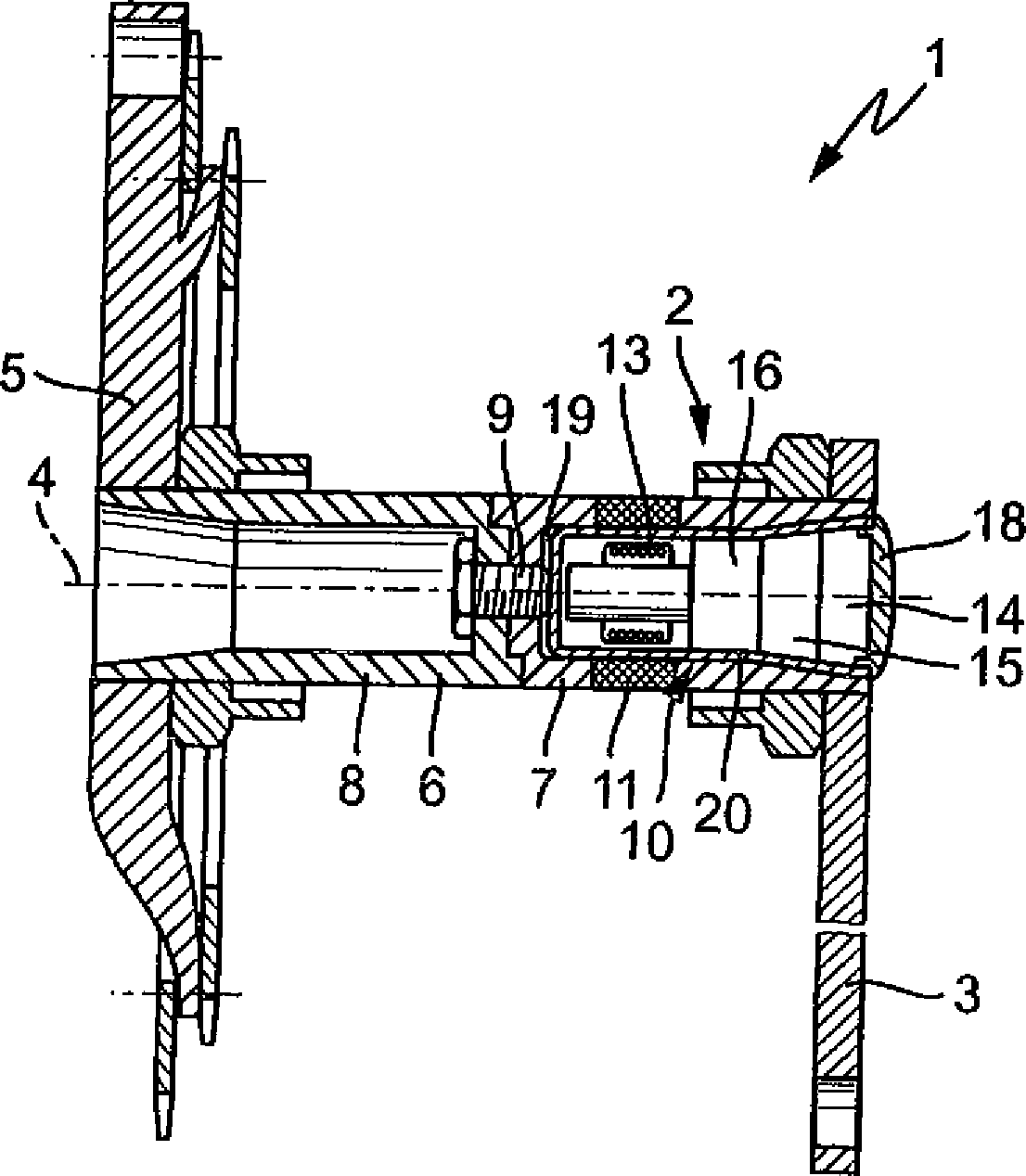
1 zeigt ein Tretlager 1 mit einer Drehmomentsensorik 2, wobei das Tretlager 1 beispielsweise für ein Fahrrad, ein Ergometer oder ein Pedelec vorgesehen sein kann. Das Tretlager 1 umfasst eine erste Tretkurbel 3, an der ein Bediener ein Drehmoment um eine Achse 4 des Tretlagers 1 in dieses einleitet. Das Tretlager 1 umfasst weiter eine zweite Tretkurbel 5. Beide Tretkurbeln 3, 5 sind mit einer Welle 6 drehfest verbunden, die als Hohlwelle ausgebildet ist. 1 shows a bottom bracket 1 with a torque sensor 2 , where the bottom bracket 1 For example, for a bicycle, an ergometer or a pedelec can be provided. The bottom bracket 1 includes a first crank 3 at which an operator generates a torque around an axis 4 of the bottom bracket 1 in this initiates. The bottom bracket 1 further includes a second crank 5 , Both cranks 3 . 5 are with a wave 6 rotatably connected, which is designed as a hollow shaft.

Die Welle 6 ist zweiteilig ausgebildet und umfasst eine erste Teilhohlwelle 7 und eine an der ersten Teilhohlwelle 7 drehfest befestigte zweite Teilhohlwelle 8. Die erste Teilhohlwelle 7 ist mit der ersten Tretkurbel 3 drehfest befestigt, so dass eine Drehung der ersten Tretkurbel 3 um die Achse 4 eine Drehung der ersten Teilhohlwelle 7 und der Welle 6 insgesamt um die Achse 4 bewirkt. Die beiden Teilhohlwellen 7, 8 sind als einseitig offene Hohlzylinder ausgebildet mit einer geschlossenen Stirnseite. Die erste Teilhohlwelle 7 und die zweite Teilhohlwelle 8 weisen jeweils an der einander zugekehrten Stirnseite eine komplementäre Strukturierung in Form einer Verzahnung auf, so dass eine Drehfestigkeit der Fügung der beiden Teilhohlwellen 7, 8 ermöglicht ist. Weiter sind die beiden Teilhohlwellen 7, 8 durch ein gemeinsames Verbindungsmittel 9, spezielle eine Schraube, aneinander befestigt und in axialer Richtung aneinander festgelegt.The wave 6 is formed in two parts and includes a first part hollow shaft 7 and one on the first part hollow shaft 7 rotatably mounted second part hollow shaft 8th , The first part hollow shaft 7 is with the first pedal 3 secured against rotation, allowing a rotation of the first crank 3 around the axis 4 a rotation of the first partial hollow shaft 7 and the wave 6 total around the axis 4 causes. The two partial hollow shafts 7 . 8th are designed as unilaterally open hollow cylinder with a closed end face. The first part hollow shaft 7 and the second partial hollow shaft 8th each have on the facing end face a complementary structuring in the form of a Gearing on, so that a torsional strength of the join of the two partial hollow shafts 7 . 8th is possible. Next are the two partial hollow shafts 7 . 8th by a common connecting means 9 , a special screw, attached to each other and fixed together in the axial direction.

Das Tretlager 1 umfasst weiter eine Drehmomenterfassungsvorrichtung 10 zur Erfasssung des durch die beiden Tretkurbeln 3, 5 eingeleiteten Drehmomentes. Die Drehmomenterfassungsvorrichtung 10 umfasst eine erste Magnetisierung 11, die im Bereich der ersten Teilhohlwelle 7 in Richtung der axialen Erstreckung der ersten Teilhohlwelle 7 abschnittsweise das Korpus der ersten Teilhohlwelle 7 umlaufend angebracht ist. Die Drehmomenterfassungsvorrichtung 10 umfasst weiter einen der ersten Magnetisierung 11 zugeordneten ersten Sensor 12, der so ausgelegt und bezogen auf die erste Magnetisierung 11 so angeordnet ist, dass er eine Änderung des Magnetfeldes der ersten Magnetisierung 11 erfassen kann.The bottom bracket 1 further comprises a torque detecting device 10 to capture the through the two cranks 3 . 5 initiated torque. The torque detecting device 10 includes a first magnetization 11 , which are in the range of the first partial hollow shaft 7 in the direction of the axial extent of the first partial hollow shaft 7 in sections, the body of the first part hollow shaft 7 circumferentially attached. The torque detecting device 10 further includes one of the first magnetization 11 associated first sensor 12 which is so designed and related to the first magnetization 11 is arranged so that it changes the magnetic field of the first magnetization 11 can capture.

Der erste Sensor 12 umfasst ein magnetisches Erfassungmittel 13, das als Spule ausgebildet ist, eine Energieversorgungseinheit 14, eine Telemetrieeinheit 15 und eine Auswerteelektronik 16 mit einem Verstärker. Das magnetische Erfassungsmittel 13 erfasst das Magnetfeld der ersten Magnetisierung 11, zumindest aber eine Änderung der ersten Magnetisierung 11 und übermittelt das erfasste Signal über die Telemetrieeinheit 15 an die nachgeschaltete Auswerteelektronik 16 mit dem Verstärker. Die Energieversorgungseinheit 14 beaufschlagt das magnetische Erfassungsmittel 13 sowie die weiteren Komponenten des ersten Sensors 12. Das magnetische Erfassungsmittel 13, die Telemetrieeinheit 15, die Auswerteelektronik 16 und die Energieversorgungseinheit 14 sind zu einer baulichen Einheit 17 zusammengefasst, die nach Art einer Patrone ausgebildet ist und deren äussere Gestalt so ausgebildet ist, dass die bauliche Einheit 17 in der ersten Teilhohlwelle 7 im wesentlichen formschlüssig aufgenommen ist.The first sensor 12 comprises a magnetic detection means 13 formed as a coil, a power supply unit 14 , a telemetry unit 15 and an evaluation 16 with an amplifier. The magnetic detection means 13 detects the magnetic field of the first magnetization 11 , but at least a change of the first magnetization 11 and transmits the detected signal via the telemetry unit 15 to the downstream evaluation electronics 16 with the amplifier. The power supply unit 14 acts on the magnetic detection means 13 as well as the other components of the first sensor 12 , The magnetic detection means 13 , the telemetry unit 15 , the transmitter 16 and the power supply unit 14 are a structural unit 17 summarized, which is designed in the manner of a cartridge and whose outer shape is formed so that the structural unit 17 in the first part hollow shaft 7 is received in a form-fitting manner.

Das magnetische Erfassungsmittel 13 ist in der baulichen Einheit 17 so angeordnet, dass in der montierten Stellung der baulichen Einheit 17 in der ersten Teilhohlwelle 7 die Spule in unmittelbarer Nähe zu der ersten Magnetisierung 11 angeordnet ist. Bei der Montage der baulichen Einheit 17 wird das magnetische Erfassungsmittel 13 damit lagerichtig zu der ersten Magnetisierung 11 positioniert. Die bauliche Einheit 17 umfasst weiter ein Deckelelement 18, das die bauliche Einheit 17 abschliesst. An einem von dem Deckelement 18 abgekehrten Ende der baulichen Einheit 17 ist ein Festlegungsabschnitt 19 vorgesehen, an dem die in die erste Teilhohlwelle 7 eingeführte bauliche Einheit 17 an der ersten Teilhohlwelle 7 und damit an der Welle 6 insgesamt festgelegt werden kann. Der Festlegungsabschnitt 19 umfasst ein Innengewinde, in das das Gewinde des als Schraube ausgebildeten gemeinsamen Verbindungsmittels 9 der beiden Teilhohlwellen 7, 8 abschnittweise eingeschraubt ist. An dem dem Deckelelement 18 zugekehrten Ende weist die bauliche Einheit einen Einführabschnitt 20 auf, an dem sie sich V-förmig aufweitet, und an dem sich die Materialdicke der ersten Teilhohlwelle 7 entsprechend reduziert.The magnetic detection means 13 is in the structural unit 17 arranged so that in the assembled position of the structural unit 17 in the first part hollow shaft 7 the coil in close proximity to the first magnetization 11 is arranged. During assembly of the structural unit 17 becomes the magnetic detection means 13 thus in the correct position for the first magnetization 11 positioned. The structural unit 17 further comprises a cover element 18 that is the structural unit 17 concludes. At one of the cover element 18 turned away end of the structural unit 17 is a fixing section 19 provided, in which the in the first partial hollow shaft 7 introduced structural unit 17 at the first partial hollow shaft 7 and thus on the wave 6 can be determined in total. The fixing section 19 includes an internal thread into which the thread of the common connecting means formed as a screw 9 the two partial hollow shafts 7 . 8th is screwed in sections. At the lid element 18 facing end, the structural unit has an insertion section 20 on, where it widens V-shaped, and at which the material thickness of the first part of the hollow shaft 7 reduced accordingly.

Ist die bauliche Einheit 17 wie in 1 dargestellt in die erste Teilhohlwelle 17 eingeführt und festgelegt, kann diese als erster Sensor 12 eine Änderung des Magnetfeldes der ersten Magnetisierung 11 erfassen. Eine derartige Änderung tritt aufgrund des magnetostriktiven Effektes in dem Material der ersten Teilhohlwelle 7 auf, wenn über eine der beiden Tretkurbeln 3, 5 ein Drehmoment in die Welle 6 eingeleitet wird.Is the structural unit 17 as in 1 shown in the first part hollow shaft 17 introduced and set, this can be the first sensor 12 a change in the magnetic field of the first magnetization 11 to capture. Such a change occurs due to the magnetostrictive effect in the material of the first partial hollow shaft 7 if on one of the two cranks 3 . 5 a torque in the shaft 6 is initiated.

In dem ersten Ausführungsbeispiel war die Welle 6 zweiteilig durch zwei aneinander befestigte Teilhohlwelle 7, 8 ausgebildet. Es versteht sich, dass zwischen den beiden Teilhohlwellen 7, 8 ein weiteres Zwischenstück, beispielsweise eine weitere Hohl- oder Vollwelle, angeordnet sein kann, und dass die bauliche Einheit 17 an diesem Zwischenstück ggf. zusätzlich festgelegt sein kann. Es versteht sich ferner, dass die Welle 6 auch über ihre gesamte axiale Erstreckung als durchgehende Hohlwelle ausgebildet sein kann. Die Festlegung der baulichen Einheit 17 kann durch eine Gewindeverbindung ausgebildet sein, wobei das Gewinde im Bereich des Einführabschnittes 20 angeordnet sein kann. Es versteht sich ebenfalls, dass die bauliche Einheit 17 auch anders als durch eine Schraubverbindung an der Welle 6 festgelegt sein kann, beispielsweise über eine Schnappverbindung oder eine Bajonettverbindung. Es versteht sich weiter, dass im Bereich der Welle 6 bzw. der die bauliche Einheit 17 aufnehmenden Teilhohlwelle 7 Führungsmittel, beispielsweise Führungsnuten, vorgesehen sein können, die ein Einfädeln der baulichen Einheit 17 erleichtern. Es ist ebenfalls nicht zwingend erforderlich, dass die bauliche Einheit 17 mit dem Deckelelement 18 bündig an der Fläche der Tretkurbel 3 abschliesst. Vielmehr kann vorgesehen sein, dass die bauliche Einheit 17 vollständig in der Welle 6, insbesondere innerhalb einer Teilhohlwelle 7, aufgenommen ist.In the first embodiment, the shaft was 6 two-piece by two attached part hollow shaft 7 . 8th educated. It is understood that between the two partial hollow shafts 7 . 8th Another intermediate piece, for example, a further hollow or solid shaft, can be arranged, and that the structural unit 17 may optionally be specified at this intermediate piece. It is further understood that the shaft 6 may also be formed over its entire axial extent as a continuous hollow shaft. The definition of the structural unit 17 can be formed by a threaded connection, wherein the thread in the region of the insertion 20 can be arranged. It is also understood that the structural unit 17 also different than by a screw on the shaft 6 may be fixed, for example via a snap connection or a bayonet connection. It goes on to be understood that in the area of the shaft 6 or the structural unit 17 receiving part hollow shaft 7 Guiding means, such as guide grooves, can be provided which thread a structural unit 17 facilitate. It is also not mandatory that the structural unit 17 with the cover element 18 flush with the surface of the crank 3 concludes. Rather, it can be provided that the structural unit 17 completely in the shaft 6 , in particular within a partial hollow shaft 7 , recorded.

Für die Beschreibung der weiteren Ausführungsbeispiele werden gleiche oder vergleichbare Elemente mit den gleichen Bezugszeichen versehen. Ausgehend von der Beschreibung des in 1 dargestellten Ausführungsbeispiels sollen insbesondere Unterschiede und Abweichungen herausgestellt werden.For the description of the further embodiments, the same or comparable elements are provided with the same reference numerals. Starting from the description of in 1 illustrated embodiment in particular differences and deviations are highlighted.

2 zeigt ein Tretlager 1 mit einer Welle 6, die als Hohlwelle ausgebildet ist, und zwei mittels eines gemeinsamen Verbindungsmittels 9, speziell einer Schraube, aneinander gefügte Teilhohlwellen 7, 8 umfasst. Der Sensor 12 ist als bauliche Einheit 17 ausgebildet und umfasst ein magnetisches Erfassungsmittel 13, speziell eine Spule, eine Telemetrieeinheit 15 und eine Auswerteeinheit 16. Dem Sensor 12 ist eine Energieversorgungseinheit 14 zugeordnet, die allerdings nicht in der baulichen Einheit 17 angeordnet ist. Die Energieversorgungseinheit 14 ist in der zweiten Teilhohlwelle 8 angeordnet und mittels einer Steckverbindung 21 in elektrischen Kontakt. Die Steckverbindung 21 umfasst ein Kontaktelement 22, das die Schraube 9 entlang der Achse 4 durchsetzt und einen elektrisch leitenden Kontakt zwischen der Energieversorgungseinheit 14 und den weiteren Komponenten des Sensors 12 herstellt. Die Energieversorgungseinheit 14 ist in einer Aufnahme 23 angeordnet, die so gestaltet ist, dass die Aufnahme 23 im wesentlichen formschlüssig in der zweiten Teilhohlwelle 8 aufgenommen ist. Bei der Montage wird die Aufnahme 23 mit der Energieversorgungseinheit 14 in die zweite Teilhohlwelle 8 eingeführt und an der zweiten Teilhohlwelle 8 beispielsweise durch Einschrauben festgelegt, dann wird die bauliche Einheit 17 mit den übrigen Kompontenten des Sensors 12 in die erste Teilhohlwelle 7 eingeführt und an der ersten Teihohlwelle 7 festgelegt. Bei dem Festlegen der baulichen Einheit 17 wird der elektrische Kontakt mit der Energieversorgungseinheit 14 hergestellt. 2 shows a bottom bracket 1 with a wave 6 , which is formed as a hollow shaft, and two by means of a common connecting means 9 . especially a screw, joined to each other part hollow shafts 7 . 8th includes. The sensor 12 is as a structural unit 17 formed and includes a magnetic detection means 13 , especially a coil, a telemetry unit 15 and an evaluation unit 16 , The sensor 12 is a power supply unit 14 but not in the structural unit 17 is arranged. The power supply unit 14 is in the second partial hollow shaft 8th arranged and by means of a plug connection 21 in electrical contact. The plug connection 21 includes a contact element 22 that the screw 9 along the axis 4 passes through and an electrically conductive contact between the power supply unit 14 and the other components of the sensor 12 manufactures. The power supply unit 14 is in a recording 23 arranged, which is designed to take the picture 23 essentially positively in the second hollow part shaft 8th is included. During assembly, the recording 23 with the power supply unit 14 in the second part hollow shaft 8th introduced and at the second part hollow shaft 8th For example, fixed by screwing, then the structural unit 17 with the other components of the sensor 12 in the first part hollow shaft 7 introduced and at the first Teihohlwelle 7 established. In determining the structural unit 17 becomes the electrical contact with the power supply unit 14 produced.

Es versteht sich, dass mehrere Kontaktelemente vorgesehen sein können, die nach Art eines Steckers die aneinander grenzenden Stirnflächen der beiden Teilhohlwellen 7, 8 durchsetzen.It is understood that a plurality of contact elements can be provided which, in the manner of a plug, the adjacent end faces of the two hollow part shafts 7 . 8th push through.

Es versteht sich weiter, dass die räumliche Trennung der Energieversorgungseinheit 14 und der übrigen Komponenten des Sensors 12 auch für eine entlang der axialen Erstreckung durchgehende, einteilige Welle 6 vorgesehen sein kann; hierbei kann die Steckverbindung 21 so ausgestaltet sein, dass ein definierter Abstand zwischen der Aufnahme 23 der Energieversorgungseinheit 14 und den übrigen Komponenten der baulichen Einheit 17 eingehalten wird, um das magnetische Erfassungsmittel 13 lagerichtig in Bezug auf die erste Magnetisierung 11 zu positionieren.It is further understood that the physical separation of the power supply unit 14 and the other components of the sensor 12 also for a along the axial extent continuous, one-piece shaft 6 can be provided; Here, the connector 21 be designed so that a defined distance between the recording 23 the power supply unit 14 and the other components of the structural unit 17 is complied with the magnetic detection means 13 in the correct position with respect to the first magnetization 11 to position.

3 zeigt ein Tretlager 1 mit einer ersten Tretkurbel 3 und einer zweiten Tretkurbel 5, wobei die beiden Tretkurbeln 3, 5 mit einer als Hohlwelle ausgebildeten Welle 6 drehfest verbunden sind. Die Welle 6 ist zweiteilig ausgebildet und umfasst eine erste, mit der ersten Tretkurbel 3 drehfest gekoppelte Teilhohlwelle 7 und eine zweite, mit der zweiten Tretkurbel 5 drehfest gekoppelte Teilhohlwelle 8, wobei die beiden Teilhohlwellen 7, 8 durch ein Verbindungsmittel 9, vorliegend eine Schraube, in axialer Richtung aneinander festgelegt werden. An den einander zugekehrten Stirnflächen weisen die beiden Teilhohlwellen 7, 8 eine zueinander komplementäre Profilierung auf, die eine verdrehsichere Festlegung der beiden Teilhohlwellen 7, 8 aneinander sicherstellt. 3 shows a bottom bracket 1 with a first pedal 3 and a second pedal 5 where the two cranks 3 . 5 with a shaft formed as a hollow shaft 6 are rotatably connected. The wave 6 is formed in two parts and includes a first, with the first pedal 3 non-rotatably coupled part hollow shaft 7 and a second, with the second pedal 5 non-rotatably coupled part hollow shaft 8th , wherein the two partial hollow shafts 7 . 8th by a connecting means 9 , in this case a screw, are fixed to each other in the axial direction. At the mutually facing end faces, the two partial hollow shafts 7 . 8th a profiling complementary to each other, the rotationally secure fixing of the two partial hollow shafts 7 . 8th ensures one another.

Im Bereich der ersten Teilhohlwelle 7 ist im Bereich des Aussenumfangs abschnittsweise eine umlaufende erste Magnetisierung 11 vorgesehen. Der ersten Magnetisierung 11 ist ein Sensor 12 zugeordnet, der ausserhalb der ersten Teilhohlwelle 7 angeordnet ist. Der Sensor 12 umfasst ein als Spule ausgebildetes magnetisches Erfassungsmittel 13, das mittels eines Kabels 24 von einer ausserhalb des Sensors 12 angeordneten Energieversorgungseinheit bzw. Anzeigeeinheit beaufschlagt wird. Der Sensor 12 ist in einer einschraubbaren Einheit 25 aufgenommen, die mittels eines einer Lageraufnahme 26 zugekehrten Aussengewindes in ein an der Lageraufnahme 26 vorgesehenes Innengewinde einschraubbar ist. Die einschraubbare Einheit 25 ist über ein Wälzlager 27 an den Aussenumfang der ersten Teilhohlwelle 7 sowie gegenüber einen nur abschnittsweise dargestellten Kettenblatthalter 28 abgestützt. Die einschraubbare Einheit 25 ist im wesentlichen konzentrisch zu der Achse 4 des Tretlagers 1 ausgerichtet und umgibt die erste Teilhohlwelle 7 mindestens abschnittsweise.In the area of the first partial hollow shaft 7 is in the area of the outer circumference in sections a circumferential first magnetization 11 intended. The first magnetization 11 is a sensor 12 assigned, the outside of the first partial hollow shaft 7 is arranged. The sensor 12 comprises a magnetic detection means designed as a coil 13 that by means of a cable 24 from outside the sensor 12 arranged power supply unit or display unit is acted upon. The sensor 12 is in a screw-in unit 25 taken up by means of a bearing receiver 26 facing external thread in a at the camp admission 26 provided internal thread can be screwed. The screw-in unit 25 is about a rolling bearing 27 on the outer circumference of the first hollow part shaft 7 and against a chainring holder shown only in sections 28 supported. The screw-in unit 25 is substantially concentric with the axis 4 of the bottom bracket 1 aligned and surrounds the first part hollow shaft 7 at least in sections.

Es versteht sich, dass alternativ eine einschraubbare Einheit 25 vorgesehen sein kann, die nur an einer Seite der Teilhohlwelle 7 bzw. der Welle 6 vorgesehen ist, und die mit ihrem Aussengewinde in die Lageraufnahme 26 bzw. einen Abschnitt der Welle 6 einschraubbar ist. Eine derartige einschraubbare Einheit ist nach Art einer einfachen Schraube ausgestaltet, in der der Sensor 12 baulich integriert ist.It is understood that alternatively a screw-in unit 25 may be provided, which only on one side of the hollow part shaft 7 or the shaft 6 is provided, and with its external thread in the bearing receptacle 26 or a section of the shaft 6 can be screwed. Such a screw-in unit is designed in the manner of a simple screw, in which the sensor 12 structurally integrated.

4 zeigt eine einschraubbare Einheit 25 mit einem Kabel 24 und einer Lageraufnahme 26 für den Fall einer als Hohlwelle ausgestalteten Welle 6, die einteilig und entlang ihrer axialen Erstreckung durchgehend ausgebildet ist. Dabei ist die Tretkurbel 3 an der dem Kettenblatthalter 28 abgewandten Seite abnehmbar, um die Montierbarkeit des Systems sicherzustellen. 4 shows a screw-in unit 25 with a cable 24 and a camp recording 26 in the case of a shaft designed as a hollow shaft 6 , which is formed integrally and continuously along its axial extent. Here is the pedal 3 at the chainring holder 28 Removable side to ensure the mountability of the system.

5 zeigt ein Tretlager 1 mit einer ersten Tretkurbel 3 und einer zweiten Tretkurbel 5, die jeweils drehfest mit einer als Hohlwelle ausgebildeten Welle 6 verbunden sind. Die Welle 6 ist zweiteilig ausgebildet und umfasst eine erste Teilhohlwelle 7 und eine zweite Teilhohlwelle 8. Die zweite Teilhohlwelle 8 ist unmittelbar mit der zweiten Tretkurbel 5 drehfest verbunden. 5 shows a bottom bracket 1 with a first pedal 3 and a second pedal 5 , each non-rotatably with a shaft formed as a hollow shaft 6 are connected. The wave 6 is formed in two parts and includes a first part hollow shaft 7 and a second partial hollow shaft 8th , The second part hollow shaft 8th is directly with the second pedal 5 rotatably connected.

Die erste Tretkurbel 3 ist unmittelbar mit einer Tretkurbelwelle 29 drehfest verbunden, wobei die Tretkurbelwelle 29 in der ersten Teilhohlwelle 7 aufgenommen ist und zu den innenseitigen Wandflächen der hohlzylindrisch ausgebildeten ersten Teilhohlwelle 7 einen Abstand einhält. Die erste Teilhohlwelle 7, die zweite Teilhohlwelle 8 und die Tretkurbelwelle 29 sind untereinander mittels eines gemeinsamen Verbindungsmittels 9, in dem dargestellten Ausführungsbeispiel mittels einer Schraube, aneinander verdrehsicher zur Übertragung des Drehmomentes befestigt. Insbesondere ist die erste Tretkurbel 3 unter Zwischenschaltung der Tretkurbelwelle 29 an der ersten Teilhohlwelle 7 und damit an der Welle 6 indirekt drehfest angeordnet. An der ersten Teilhohlwelle 7 ist endseitig nach Art eines im wesentlichen senkrecht abgestellten Abschnittes ein Kettenblatthalter 28 angeordnet, wobei die Teilhohlwelle 7 an einem Endabschnitt 35 der einschraubbaren Einheit 25 gelagert ist und den Kettenblatthalter 28 abstützt. Der Kettenblatthalter 28 stützt Kettenblätter, an denen die Kette, die der Bediener über die beiden Tretkurbeln 3, 5 antreibt, gelagert und geführt werden kann.The first pedal 3 is directly with a pedal crankshaft 29 rotatably connected, with the pedal crankshaft 29 in the first part hollow shaft 7 is received and to the inside wall surfaces of the hollow cylindrical first hollow part shaft 7 keeps a distance. The first Part hollow shaft 7 , the second partial hollow shaft 8th and the crankshaft 29 are mutually by means of a common connection means 9 , in the illustrated embodiment by means of a screw, against each other secured against rotation for transmitting the torque. In particular, the first pedal is 3 with the interposition of the pedal crankshaft 29 at the first partial hollow shaft 7 and thus on the wave 6 arranged indirectly rotatably. At the first part hollow shaft 7 is a chainring holder at the end in the manner of a substantially vertical parked section 28 arranged, wherein the partial hollow shaft 7 at one end portion 35 the screw-in unit 25 is stored and the chainring holder 28 supported. The chainring holder 28 supports chainrings, which hold the chain, the operator over the two cranks 3 . 5 can be driven, stored and guided.

Das Tretlager 1 umfasst weiter eine Drehmomentsensorik mit einer Drehmomenterfassungsvorrichtung 2, die eine erste Magnetisierung 11 mit einem ersten Sensor 12 umfasst. Die erste Magnetisierung 11 ist im Bereich der ersten Teilhohlwelle 7 an der äusseren Umfangsfläche abschnittsweise vorgesehen. Der erste Sensor 12 umfasst zwei magnetische Erfassungsmittel 13, die als zwei axial beabstandete Spulen ausgebildetsind. Die Drehmomenterfassungsvorrichtung umfasst weiter eine zweite Magnetisierung 30, die als magnetisierter Abschnitt in einem axialen Abstand zu der ersten Magnetisierung 11 im Bereich des Aussenumfangs der zweiten Teilhohlwelle 8 angeordnet ist. Der zweiten Magnetisierung 30 ist ein zweiter Sensor 31 zugeordnet, der zwei magnetische Erfassungsmittel 13, die ebenfalls als Spulen ausgebildet sind, umfasst, wobei die beiden Spulen des zweiten Sensors 31 einen axialen Abstand aufweisen. Die je zwei Spulen der beiden Sensoren 12, 31 sind insgesamt auf einer einschraubbaren Einheit 25 aufgenommen, die über ein Gewinde an der Lageraufnahme 26 einschraubbar ist. Die Anordnung der Spulen in der einschraubbaren Einheit 25 ist so getroffen, dass in der eingeschraubten Stellung der einschraubbaren Einheit die Spulen der beiden Sensoren 12, 31 jeweils lagerichtig zu den zugeordneten Magnetisierungen 11, 30 angeordnet ist. Die einschraubbare Einheit 25 stützt sich mittels eines Wälzlagers 27 an der Welle 6 ab. Die einschraubbare Einheit 25 erfüllt damit zwei Funktionen, nämlich den Sensor 12 bzw. beide Sensoren 12, 31 aufzunehmen sowie eine Lagerung und Aufnahme der Welle 6 darzustellen.The bottom bracket 1 further comprises a torque sensor with a torque detecting device 2 that is a first magnetization 11 with a first sensor 12 includes. The first magnetization 11 is in the range of the first partial hollow shaft 7 provided in sections on the outer peripheral surface. The first sensor 12 includes two magnetic detection means 13 which are formed as two axially spaced coils. The torque detecting device further includes a second magnetization 30 acting as a magnetized section at an axial distance to the first magnetization 11 in the region of the outer circumference of the second hollow part shaft 8th is arranged. The second magnetization 30 is a second sensor 31 associated with the two magnetic detection means 13 , which are also formed as coils comprises, wherein the two coils of the second sensor 31 have an axial distance. The two coils of the two sensors 12 . 31 are altogether on a screw-in unit 25 taken up, which has a thread on the bearing mount 26 can be screwed. The arrangement of the coils in the screw-in unit 25 is made such that in the screwed position of the screw-in unit, the coils of the two sensors 12 . 31 each in the correct position to the associated magnetizations 11 . 30 is arranged. The screw-in unit 25 supported by a rolling bearing 27 on the shaft 6 from. The screw-in unit 25 thus fulfills two functions, namely the sensor 12 or both sensors 12 . 31 as well as a bearing and receiving the shaft 6 display.

Die Welle 6 wird im Bereich der Teilhohlwelle 7 durch eine weitere Stützeinheit 32 gegen die Lageraufnahme 26 abgestützt, wobei die Stützeinheit 32 in die Lageraufnahme 26 abschnittsweise eingeschraubt ist und sich gegen die Welle mittels eines weiteren Wälzlagers 33 abstützt.The wave 6 becomes in the area of the partial hollow shaft 7 through another support unit 32 against the camp admission 26 supported, wherein the support unit 32 in the warehouse 26 is screwed in sections and against the shaft by means of another rolling bearing 33 supported.

5 zeigt weiter eine Anzeigeeinheit 34, die die von den Sensoren 12, 31 erfassten, bereits innerhalb der einschraubbaren Einheit 26 ausgewerteten Drehmomente bzw. Leistungen dem Bediener des Tretlagers 1 sichtbar macht. 5 further shows a display unit 34 that's from the sensors 12 . 31 already inside the screw-in unit 26 Evaluated torques or services to the operator of the bottom bracket 1 makes visible.

Bei Betrieb des Tretlagers 1 erfasst der erste Sensor 12 die im Bereich der ersten Magnetisierung 11 auftretenden Spannungen in dem Material der ersten Teilhohlwelle 7 und der zweite Sensor 31 die im Bereich der zweiten Magnetisierung 30 auftretenden Spannungen in dem Material der Welle 6. Aufgrund der zwischen der ersten Tretkurbel 3 und der ersten Teilhohlwelle 7 zwischengeschalteten Tretkurbelwelle 29 erfasst der zweite Sensor 31 im wesentlichen die bei der Betätigung der ersten Tretkurbel 3 eingebrachten Drehmomente, speziell also das Drehmoment aufgrund der Betätigung durch das eine Bein des Bedieners, das die erste Tretkurbel 3 antreibt. Der zweite Sensor 31 erfasst im wesentlichen die insgesamt in der Welle 6 auftretenden Drehmomente, also die Überlagerung der von beiden Tretkurbeln 3, 5 eingebrachten Drehmomente. Durch Differenzbildung der von beiden Sensoren 12, 31 erfassten Drehmomente lässt sich das von der zweiten Tretkurbel 5 eingebrachte Drehmoment rechnerisch ermitteln und in der Anzeigeeinheit 34 dem Bediener angeben.When operating the bottom bracket 1 detects the first sensor 12 in the area of the first magnetization 11 occurring stresses in the material of the first part of the hollow shaft 7 and the second sensor 31 in the area of the second magnetization 30 occurring stresses in the material of the shaft 6 , Because of between the first pedal 3 and the first part hollow shaft 7 intermediate pedal crankshaft 29 detects the second sensor 31 essentially when you press the first crank 3 introduced torques, specifically the torque due to the operation by the one leg of the operator, the first pedal crank 3 drives. The second sensor 31 essentially captures the total in the wave 6 occurring torques, so the superposition of the two cranks 3 . 5 introduced torques. By subtraction of the two sensors 12 . 31 detected torques can be that of the second crank 5 Calculate introduced torque by calculation and in the display unit 34 indicate to the operator.

Das Tretlager 1 umfasst weiter einen Drehzahlaufnehmer 36, der in der einschraubbaren Einheit 25 angeordnet ist und von den je zwei Spulen 13 der beiden Sensoren 12, 31 beabstandet angeordnet ist. Der Drehzahlaufnehmer 36 erfasst die aufgrund des insgesamt eingebrachten Drehmomentes von der Welle 6 ausgeführte Drehzahl, also die Winkelgeschwindigkeit und damit die Zahl der Umdrehungen der Welle 6 pro Zeiteinheit. Der Drehzahlaufnehmer 36 kann durch eine geeignete optische oder magnetische Markierung und eine geeignete optische oder magnetische Erfassung gebildet sein und ermitteln, wie viele Markierungen in der Zeiteinheit erfasst werden. Es versteht sich, dass eine der Magnetisierungen 11, 30 derart ausgebildet werden kann, dass eine Markierung vorgesehen ist, die durch die Sensoren 12, 31 erfassbar ist, so dass der Drehzahlaufnehmer in die Drehmomenterfassungsvorrichtung 2 integriert sein kann. Es versteht sich ferner, dass der Drehzahlaufnehmer auch ausserhalb des Tretlagers 1 vorgesehen sein kann und beispielsweise die Geschwindigkeit der Kette erfassen kann, die durch das Tretlager 1 angetrieben wird. Alternativ oder ergänzend hierzu kann der Drehzahlaufnehmer eine Lichtschranke umfassen, die ermittelt, wie oft pro Zeiteinheit eine der beiden Tretkurbeln 3, 5 eine Umdrehung durchfährt.The bottom bracket 1 further includes a speed sensor 36 in the screw-in unit 25 is arranged and of the two coils 13 the two sensors 12 . 31 spaced apart. The speed sensor 36 detects the due to the total torque introduced by the shaft 6 executed speed, ie the angular velocity and thus the number of revolutions of the shaft 6 per time unit. The speed sensor 36 may be formed by a suitable optical or magnetic marker and a suitable optical or magnetic detection and determine how many markers are detected in the unit time. It is understood that one of the magnetizations 11 . 30 can be formed such that a mark is provided by the sensors 12 . 31 is detectable, so that the speed sensor in the torque detecting device 2 can be integrated. It is further understood that the speed sensor also outside of the bottom bracket 1 may be provided and, for example, can detect the speed of the chain passing through the bottom bracket 1 is driven. Alternatively or additionally, the speed sensor may include a light barrier, which determines how often per unit time one of the two cranks 3 . 5 one turn through.

Ist durch die Drehmomenterfassungsvorrichtung 2 das Drehmoment und durch den Drehzahlaufnehmer 36 die Drehzahl des Tretlagers 1 bekannt, lässt sich die durch den Bediener des Tretlagers 1 erbrachte Leistung durch Multiplikation berechnen. Das gilt sowohl für die insgesamt erbrachte Leistung als auch die von jedem Bein des Bedieners an jedem der beiden Tretkurbeln 3, 5 erbrachte Leistung, die voneinander unabhängig erfasst und ermittelt werden kann.Is through the torque detecting device 2 the torque and the speed sensor 36 the speed of the bottom bracket 1 known, can by the operator of the bottom bracket 1 Calculate performance by multiplication. This applies to both the overall performance and that of each leg of the operator on each of the two cranks 3 . 5 provided, which can be independently recorded and determined.

Bei dem vorstehend beschriebenen Ausführungsbeispiel umfasste jeder der beiden Sensoren 12, 31 je zwei voneinander beabstandete Spulen als magnetische Erfassungsmittel 13 für die beiden Magnetisierungen 11, 30. Es versteht sich, dass beide Sensoren 12, 31 ein gemeinsames magnetisches Erfassungsmittel aufweisen können, beispielsweise eine einzige, beiden Sensoren 12, 31 gemeinsame Spule, die sich entlang der axialen Ausdehnung der einschraubbaren Einheit 25 erstreckt. Die gemeinsame Spule erfasst in einem ersten Abschnitt im Bereich der ersten Magnetisierung 11 eine erste Spannung und in einem zweiten Abschnitt im Bereich der zweiten Magnetisierung 30 eine zweite Spannung. Über die gesamte Erstreckung der gemeinsamen Spule resultiert eine dritte Spannung, die sich als vorzeichenrichtige Summe der ersten und der zweiten Spannung ergibt. Die der Änderung der ersten Magnetisierung 11 entsprechende erste Spannung kann an der Spule abgegriffen werden; ebenso die zweite Spannung sowie die resultierende Gesamtspannung. Auf diese Weise lassen sich zwei oder mehrere der Drehmomente durch ein einziges magnetisches Erfassungsmittel, insbesondere eine einzige Spule, simultan erfassen und jeweils einzeln auslesen.In the embodiment described above, each of the two sensors included 12 . 31 two spaced apart coils as magnetic detection means 13 for the two magnetizations 11 . 30 , It is understood that both sensors 12 . 31 may comprise a common magnetic detection means, for example, a single, two sensors 12 . 31 common coil, extending along the axial extent of the screw-in unit 25 extends. The common coil detects in a first section in the region of the first magnetization 11 a first voltage and in a second portion in the region of the second magnetization 30 a second tension. Over the entire extent of the common coil results in a third voltage, which results in the correct sign sum of the first and the second voltage. The change of the first magnetization 11 corresponding first voltage can be tapped on the coil; as well as the second voltage and the resulting total voltage. In this way, two or more of the torques can be detected simultaneously by a single magnetic detection means, in particular a single coil and read out individually.

Es versteht sich ebenfalls, dass das über die erste Tretkurbel 3 eingebrachte Drehmoment auch durch eine an der Tretkurbelwelle 29 oder eine an der Innenseite der erste Teilhohlwelle 7 angeordnete erste Magnetisierung 11 erfasst werden kann.It goes without saying that this is about the first pedal 3 introduced torque also by a at the crankshaft 29 or one on the inside of the first part hollow shaft 7 arranged first magnetization 11 can be detected.

Bei dem vorstehend beschriebenen fünften Ausführungsbeispiel war die Tretkurbelwelle 29 als Vollwelle ausgebildet. Es versteht sich, dass die Tretkurbelwelle 29 auch als Hohlwelle ausgebildet sein kann.In the fifth embodiment described above, the pedal crankshaft was 29 designed as a solid shaft. It is understood that the crankshaft 29 can also be designed as a hollow shaft.

Bei der für das dritte, vierte und fünfte Ausführungsbeispiel beschriebenen einschraubbaren Einheit 25 versteht es sich, dass die gesamte oder ein Teil der Auswerteelektronik in die einschraubbare Einheit 25 baulich integriert sein kann (z. B. als Flexboard).In the screw-in unit described for the third, fourth and fifth embodiments 25 It is understood that all or part of the transmitter in the screw-in unit 25 structurally integrated (eg as a flexboard).

Es versteht sich, dass die fünf vorbeschriebenen Ausführungsbeispiele, einschliesslich der angedeuteten Abwandlungen, untereinander kombiniert werden können.It is understood that the five above-described embodiments, including the indicated modifications, can be combined with each other.

Beispielsweise kann ausgehend von dem fünften Ausführungsbeispiel (5) die Erfassung der Änderung der zweiten Magnetisierung 30 durch eine im Bereich der zweiten Teilhohlwelle 8 angeordnete bauliche Einheit 17 ausgeführt werden, wie sie in Bezug auf die ersten beiden Ausführungsbeispiele (1 und 2) beschrieben wurde.For example, starting from the fifth embodiment ( 5 ) the detection of the change of the second magnetization 30 by one in the region of the second partial hollow shaft 8th arranged structural unit 17 be carried out as described with respect to the first two embodiments ( 1 and 2 ) has been described.

Insofern vorstehend die magnetischen Erfassungsmittel 13 als Spulen ausgebildet wurden, versteht es sich, dass auch andere Mittel in Frage kommen, die grundsätzlich geeignet sind, die Änderung eines Magnetfeldes zu erfassen, wie beispielsweise Hall-Sensoren oder Reed-Sensoren.Insofar as above, the magnetic detection means 13 As coils were formed, it is understood that other means come into question, which are in principle suitable to detect the change of a magnetic field, such as Hall sensors or reed sensors.

Insofern vorstehend auf die Ausbildung der Welle 6 als Hohlwelle Bezug genommen wurde, versteht es sich, dass es ausreichend sein kann, dass die Welle 6 nur abschnittsweise als Hohlwelle ausgebildet ist, beispielsweise im Bereich der drehfesten Verbindung mit einer der Tretkurbeln 3, 5, und im übrigen als Vollwelle ausgebildet ist. Es versteht sich ferner, dass die beiden Teilhohlwellen 7, 8 nicht entlang ihrer Stirnflächen im wesentlichen flächig aneinanderstossen müssen; es kann vielmehr ausreichend sein, wenn diese als beidseitig offene Hohlzylinder ausgebildet sind und nur entlang der kreisringförmigen Stirnfläche eine im wesentlichen linienhafte Verbindung aufweisen. Es versteht sich ferner, dass eine der beiden Teihohlwellen 7, 8 auch abschnittsweise in der anderen der beiden Teilhohlwellen aufgenommen sein kann. Auch kann vorgesehen sein, dass die beiden Teilhohlwellen als beidseitig offene Hohlzylinder ausgebildet sind und ein Zwischenelement abschnittsweise in jeder der beiden Teilhohlwellen aufgenommen ist, wobei das Zwischenelement zur Verbindung der beiden Teilhohlwellen miteinander vorgesehen ist. Im Bereich des Zwischenelementes wäre dann die Welle als Vollwelle anzusehen, da das Zwischenelement den Hohlraum der jeweiligen Abschnitte der Teilhohlwellen ausfüllt.Insofar as above on the formation of the wave 6 has been referred to as a hollow shaft, it is understood that it may be sufficient that the shaft 6 only partially formed as a hollow shaft, for example in the field of non-rotatable connection with one of the cranks 3 . 5 , and otherwise designed as a solid shaft. It is further understood that the two partial hollow shafts 7 . 8th do not have to collide substantially flat along their faces; Rather, it may be sufficient if these are designed as a hollow cylinder open on both sides and only along the annular end face have a substantially linear connection. It is further understood that one of the two Teihohlwellen 7 . 8th can also be added in sections in the other part of the hollow shafts. It can also be provided that the two partial hollow shafts are designed as hollow cylinders open on both sides and an intermediate element is received in sections in each of the two partial hollow shafts, wherein the intermediate element is provided with each other for connecting the two partial hollow shafts. In the area of the intermediate element, the shaft would then have to be regarded as a solid shaft, since the intermediate element fills the cavity of the respective sections of the partial hollow shafts.

Bei den vorstehend beschriebenen Ausführungsbeispielen war die axiale Verbindung der beiden Teilhohlwellen 7, 8 durch ein gemeinsames, als Schraube ausgebildetes Verbindungsmittel 9 beschrieben worden. Es versteht sich, dass die Teilhohlwellen 7, 8 auch ohne ein weiteres Verbindungsmittel aneinander gefügt werden können, beispielsweise durch eine Ausbildung als Rast-, Schnapp- oder Bajonettverschluss, durch eine Klebung, durch Einpressen, oder als Pressverbund mit einem Presssitz gefügt sind, beispielsweise nachdem eines der Bauteile zuvor angewärmt wurde.In the embodiments described above, the axial connection of the two partial hollow shafts 7 . 8th by a common, designed as a screw connecting means 9 been described. It is understood that the partial hollow shafts 7 . 8th can be joined together without another connecting means, for example, by training as a snap, snap or bayonet, by gluing, by pressing, or joined as a press fit with a press fit, for example, after one of the components was previously heated.

Die Erfindung wurde für ein Tretlager 1 eines Fahrrades beschrieben. Es versteht sich, dass das Tretlager 1 ebenfalls das Tretlager eines Liegerades, eines Kettcars oder allgemeiner eines Kettenfahrzeugs sein kann, das mittels einer angetriebenen Kette antreibbar ist.The invention was for a bottom bracket 1 a bicycle described. It is understood that the bottom bracket 1 may also be the bottom bracket of a recumbent, a Kettcar or more generally a tracked vehicle, which is driven by a driven chain.

Bezugszeichenliste LIST OF REFERENCE NUMBERS

11
Tretlagerbottom bracket
22
Drehmomentsensoriktorque sensor
33
erste Tretkurbelfirst pedal
44
Achseaxis
55
zweite Tretkurbelsecond pedal
66
Weilewhile
77
erste Teilhohlwellefirst part hollow shaft
88th
zweite Teilhohlwellesecond part hollow shaft
99
Verbindungsmittelconnecting means
1010
DrehmomenterfassungsvorrichtungTorque detection device
1111
erste Magnetisierungfirst magnetization
1212
erster Sensorfirst sensor
1313
magnetisches Erfassungsmittelmagnetic detection means
1414
EnergieversorgungseinheitPower supply unit
1515
Telemetrieeinheittelemetry unit
1616
Auswerteeinheitevaluation
1717
bauliche Einheitstructural unit
1818
Deckelelementcover element
1919
Festlegungsabschnittsetting section
2020
Einführabschnittinserting
2121
Steckverbindungconnector
2222
Kontaktelementcontact element
2323
Aufnahmeadmission
2424
Kabelelectric wire
2525
einschraubbare Einheitscrew-in unit
2626
Lageraufnahmebearing seat
2727
Wälzlagerroller bearing
2828
KettenblatthalterChainring retainer
2929
Tretkurbelwellepedal crankshaft
3030
zweite Magnetisierungsecond magnetization
3131
zweiter Sensorsecond sensor
3232
Stützeinheitsupport unit
3333
weiteres Wälzlageranother rolling bearing
3434
Anzeigeeinheitdisplay unit
3535
Endabschnitt von einschraubbare EinheitEnd section of screw-in unit
3636
DrehzahlaufnehmerSpeed Sensor

ZITATE ENTHALTEN IN DER BESCHREIBUNG QUOTES INCLUDE IN THE DESCRIPTION

Diese Liste der vom Anmelder aufgeführten Dokumente wurde automatisiert erzeugt und ist ausschließlich zur besseren Information des Lesers aufgenommen. Die Liste ist nicht Bestandteil der deutschen Patent- bzw. Gebrauchsmusteranmeldung. Das DPMA übernimmt keinerlei Haftung für etwaige Fehler oder Auslassungen.This list of the documents listed by the applicant has been generated automatically and is included solely for the better information of the reader. The list is not part of the German patent or utility model application. The DPMA assumes no liability for any errors or omissions.

Zitierte PatentliteraturCited patent literature

  • DE 10301610 A1 [0004] DE 10301610 A1 [0004]
  • DE 19609981 A1 [0005] DE 19609981 A1 [0005]
  • EP 0954746 B1 [0006] EP 0954746 B1 [0006]
  • US 6644135 B1 [0007] US Pat. No. 6,644,135 B1 [0007]

Claims (14)

Tretlager mit einer Drehmomentsensorik (2), umfassend mindestens eine Tretkurbel (3, 5), eine Welle (6), die mit der mindestens einen Tretkurbel (3, 5) drehfest verbunden ist, und eine Drehmomenterfassungsvorrichtung zur Erfassung eines Drehmomentes im Bereich der Welle (6), wobei die Drehmomenterfassungsvorrichtung eine erste Magnetisierung (11) und einen Sensor (12) umfasst, der eine Änderung der ersten Magnetisierung (11) aufgrund des in die Welle (6) eingeleiteten Drehmomentes erfasst, dadurch gekennzeichnet, dass die Welle (6) als Hohlwelle ausgebildet ist, dass die erste Magnetisierung (11) mindestens an einem Abschnitt der Welle (6) angeordnet ist, dass die Hohlwelle (6) zweiteilig ausgebildet ist und eine erste Teilhohlwelle (7) und eine zweite Teilhohlwelle (8) umfasst, die drehfest miteinander verbunden sind, dass die mindestens eine Tretkurbel (3) mit einer Tretkurbelwelle (29) drehfest verbunden ist, und dass die Tretkurbelwelle (29) in der Welle (6), insbesondere in der ersten Teilhohlwelle (7), drehfest aufgenommen ist, und dass die erste Magnetisierung (11) im Bereich der ersten Teilhohlwelle (7) angeordnet ist.Bottom bracket with a torque sensor ( 2 ), comprising at least one crank ( 3 . 5 ), a wave ( 6 ) with the at least one crank ( 3 . 5 ) and a torque detecting device for detecting a torque in the region of the shaft ( 6 ), wherein the torque detecting device has a first magnetization ( 11 ) and a sensor ( 12 ), which is a change of the first magnetization ( 11 ) due to the wave ( 6 ) introduced torque, characterized in that the shaft ( 6 ) is designed as a hollow shaft, that the first magnetization ( 11 ) at least at a portion of the shaft ( 6 ) is arranged, that the hollow shaft ( 6 ) is formed in two parts and a first part hollow shaft ( 7 ) and a second partial hollow shaft ( 8th ), which are non-rotatably connected to each other, that the at least one crank ( 3 ) with a crankshaft ( 29 ) is rotatably connected, and that the crankshaft ( 29 ) in the wave ( 6 ), in particular in the first partial hollow shaft ( 7 ), is rotatably received, and that the first magnetization ( 11 ) in the region of the first partial hollow shaft ( 7 ) is arranged. Tretlager nach Anspruch 1, dadurch gekennzeichnet, dass der Sensor (12) ein magnetisches Erfassungmittel (13), insbesondere eine Spule, eine Telemetrieeinheit (15) und eine Auswerteeinheit (16) mit einer Auswerteelektronik umfasst, die als bauliche Einheit (17) zusammengefasst sind.Bottom bracket according to claim 1, characterized in that the sensor ( 12 ) a magnetic detection means ( 13 ), in particular a coil, a telemetry unit ( 15 ) and an evaluation unit ( 16 ) comprising an electronic evaluation unit, which can be used as a structural unit ( 17 ) are summarized. Tretlager nach Anspruch 2, dadurch gekennzeichnet, dass der Sensor (12) eine Energieversorgungseinheit (14) umfasst, und dass die Energieversorgungseinheit (14) in die bauliche Einheit (17) integriert ist.Bottom bracket according to claim 2, characterized in that the sensor ( 12 ) a power supply unit ( 14 ), and that the power supply unit ( 14 ) in the structural unit ( 17 ) is integrated. Tretlager nach Anspruch 1 und Anspruch 2, dadurch gekennzeichnet, dass die bauliche Einheit (17) in der ersten Teilhohlwelle (7) und eine Energieversorgungseinheit (14) des Sensors (12) in der zweiten Teilhohlwelle (8) angeordnet sind.Bottom bracket according to claim 1 and claim 2, characterized in that the structural unit ( 17 ) in the first partial hollow shaft ( 7 ) and a power supply unit ( 14 ) of the sensor ( 12 ) in the second partial hollow shaft ( 8th ) are arranged. Tretlager nach Anspruch 1, dadurch gekennzeichnet, dass der Sensor (12) in einer aussen an der Welle (6) einschraubbaren Einheit (25) angeordnet ist.Bottom bracket according to claim 1, characterized in that the sensor ( 12 ) in an outside on the shaft ( 6 ) screw-in unit ( 25 ) is arranged. Tretlager nach einem der Ansprüche 1 bis 5, dadurch gekennzeichnet, dass die erste Magentisierung (11) das Korpus der ersten Teilhohlwelle (7) das Korpus der ersten Teilhohlwelle (7) umlaufend angebracht ist.Bottom bracket according to one of claims 1 to 5, characterized in that the first magnetization ( 11 ) the body of the first partial hollow shaft ( 7 ) the body of the first partial hollow shaft ( 7 ) is circumferentially mounted. Tretlager nach einem der Ansprüche 1 bis 6, dadurch gekennzeichnet, dass die erste Teilhohlwelle (7), die zweite Teilhohlwelle (8) und die Tretkurbelwelle (29) mittels eines gemeinsamen Verbindungselementes (9) drehfest verbunden sind.Bottom bracket according to one of claims 1 to 6, characterized in that the first part hollow shaft ( 7 ), the second partial hollow shaft ( 8th ) and the crankshaft ( 29 ) by means of a common connecting element ( 9 ) are rotatably connected. Tretlager nach einem der Ansprüche 1 bis 7, dadurch gekennzeichnet, dass eine zweite Magnetisierung (30) an einem von der ersten Teilhohlwelle (7) axial beabstandeten Abschnitt der Welle (6) angeordnet ist.Bottom bracket according to one of claims 1 to 7, characterized in that a second magnetization ( 30 ) on one of the first partial hollow shaft ( 7 ) axially spaced portion of the shaft ( 6 ) is arranged. Tretlager nach Anspruch 8, dadurch gekennzeichnet, dass der zweiten Magnetisierung (30) ein zweiter Sensor (31) zugeordnet ist.Bottom bracket according to claim 8, characterized in that the second magnetization ( 30 ) a second sensor ( 31 ) assigned. Tretlager nach Anspruch 8 oder 9, dadurch gekennzeichnet, dass der erste Sensor (12) und der zweite Sensor (31) jeweils zwei Spulen als magnetische Erfassungsmittel (13) umfassen.Bottom bracket according to claim 8 or 9, characterized in that the first sensor ( 12 ) and the second sensor ( 31 ) each two coils as magnetic detection means ( 13 ). Tretlager nach Anspruch 8 oder 9, dadurch gekennzeichnet, dass der ersten Magnetisierung (11) und der zweiten Magnetisierung (30) ein gemeinsamer Sensor, insbesondere eine gemeinsame Spule, zugeordnet ist.Bottom bracket according to claim 8 or 9, characterized in that the first magnetization ( 11 ) and the second magnetization ( 30 ) is assigned a common sensor, in particular a common coil. Tretlager nach einem der Ansprüche 1 bis 11, dadurch gekennzeichnet, dass weiter ein Drehzahl-Aufnehmer (36) vorgesehen ist, der die Drehzahl der Welle (6) erfasst.Bottom bracket according to one of claims 1 to 11, characterized in that further comprises a speed sensor ( 36 ) is provided, the speed of the shaft ( 6 ) detected. Tretlager nach einem der Ansprüche 1 bis 12, dadurch gekennzeichnet, dass die beiden Teilhohlwellen (7, 8) als einseitig offene Hohlzylinder mit einer geschlossenen Stirnseite ausgebildet sind.Bottom bracket according to one of claims 1 to 12, characterized in that the two partial hollow shafts ( 7 . 8th ) are formed as unilaterally open hollow cylinder with a closed end face. Fahrrad, Ergometer oder Pedelec, umfassend ein Tretlager nach einem der Ansprüche 1 bis 13.Bicycle, ergometer or pedelec comprising a bottom bracket according to one of claims 1 to 13.
DE202007019291U 2007-12-21 2007-12-21 Bottom bracket with torque sensors Expired - Lifetime DE202007019291U1 (en)

Priority Applications (1)

Application Number Priority Date Filing Date Title
DE202007019291U DE202007019291U1 (en) 2007-12-21 2007-12-21 Bottom bracket with torque sensors

Applications Claiming Priority (1)

Application Number Priority Date Filing Date Title
DE202007019291U DE202007019291U1 (en) 2007-12-21 2007-12-21 Bottom bracket with torque sensors

Publications (1)

Publication Number Publication Date
DE202007019291U1 true DE202007019291U1 (en) 2012-01-02

Family

ID=45557541

Family Applications (1)

Application Number Title Priority Date Filing Date
DE202007019291U Expired - Lifetime DE202007019291U1 (en) 2007-12-21 2007-12-21 Bottom bracket with torque sensors

Country Status (1)

Country Link
DE (1) DE202007019291U1 (en)

Cited By (9)

* Cited by examiner, † Cited by third party
Publication number Priority date Publication date Assignee Title
EP2799327A1 (en) 2013-05-03 2014-11-05 Methode Electronics Malta Ltd. A freewheel hub comprising a magneto-elastic sensor and bicycle, pedelec, fast pedelec or e-bike comprising the freewheel hub
CN106275226A (en) * 2016-08-31 2017-01-04 太仓市悦博电动科技有限公司 A kind of for bicycle or the bilateral energy meter of motive-force-assisted bicycle
DE102016201455B3 (en) * 2016-02-01 2017-06-01 Schaeffler Technologies AG & Co. KG Measuring device and method for determining operating parameters on shafts
DE102017108471A1 (en) * 2017-04-20 2018-10-25 Trafag Ag Sensor head, combination sensor, torque measuring assembly and method of measuring torque and speed
CN109895929A (en) * 2017-12-07 2019-06-18 弗莱克斯有限公司 Electric clutch for electric assisted bicycle
DE102018211476A1 (en) * 2018-07-11 2020-01-16 Robert Bosch Gmbh Device for determining a torque on a shaft
DE102018124644A1 (en) * 2018-10-05 2020-04-09 Trafag Ag Bottom bracket arrangement and sports equipment provided with it
EP3743175A4 (en) * 2018-01-26 2021-10-20 Michael Grassi Shaft minimizing ellipticalization strain error
DE102022115941B3 (en) 2022-06-27 2023-11-16 Porsche Ebike Performance Gmbh Bicycle bottom bracket assembly

Citations (4)

* Cited by examiner, † Cited by third party
Publication number Priority date Publication date Assignee Title
DE19609981A1 (en) 1996-03-14 1997-09-18 Dietrich Gerhard Ellsaesser Inner bearing unit as torque-rpm sensor system for exercise cycle or ergometer
EP0954746B1 (en) 1997-11-27 2002-06-12 Siegfried Gerlitzki Method for determining the torque exerted on a rotating body which can be rotationally driven around a rotational axis
US6644135B1 (en) 1998-09-01 2003-11-11 Shimano, Inc. Torque sensor for a bicycle bottom bracket assembly
DE10301610A1 (en) 2003-01-17 2004-08-12 Ellsäßer, Dietrich Gerhard Sensor bearing for use in angular displacement and velocity measurements or torque measurements, has bearing shells with magnetic fields that are detected by a flux sensor

Patent Citations (4)

* Cited by examiner, † Cited by third party
Publication number Priority date Publication date Assignee Title
DE19609981A1 (en) 1996-03-14 1997-09-18 Dietrich Gerhard Ellsaesser Inner bearing unit as torque-rpm sensor system for exercise cycle or ergometer
EP0954746B1 (en) 1997-11-27 2002-06-12 Siegfried Gerlitzki Method for determining the torque exerted on a rotating body which can be rotationally driven around a rotational axis
US6644135B1 (en) 1998-09-01 2003-11-11 Shimano, Inc. Torque sensor for a bicycle bottom bracket assembly
DE10301610A1 (en) 2003-01-17 2004-08-12 Ellsäßer, Dietrich Gerhard Sensor bearing for use in angular displacement and velocity measurements or torque measurements, has bearing shells with magnetic fields that are detected by a flux sensor

Cited By (12)

* Cited by examiner, † Cited by third party
Publication number Priority date Publication date Assignee Title
EP2799327A1 (en) 2013-05-03 2014-11-05 Methode Electronics Malta Ltd. A freewheel hub comprising a magneto-elastic sensor and bicycle, pedelec, fast pedelec or e-bike comprising the freewheel hub
DE102016201455B3 (en) * 2016-02-01 2017-06-01 Schaeffler Technologies AG & Co. KG Measuring device and method for determining operating parameters on shafts
CN106275226A (en) * 2016-08-31 2017-01-04 太仓市悦博电动科技有限公司 A kind of for bicycle or the bilateral energy meter of motive-force-assisted bicycle
DE102017108471A1 (en) * 2017-04-20 2018-10-25 Trafag Ag Sensor head, combination sensor, torque measuring assembly and method of measuring torque and speed
CN109895929A (en) * 2017-12-07 2019-06-18 弗莱克斯有限公司 Electric clutch for electric assisted bicycle
EP3743175A4 (en) * 2018-01-26 2021-10-20 Michael Grassi Shaft minimizing ellipticalization strain error
US11390346B2 (en) 2018-01-26 2022-07-19 Michael Grassi Shaft minimizing ellipticalization strain error
DE102018211476A1 (en) * 2018-07-11 2020-01-16 Robert Bosch Gmbh Device for determining a torque on a shaft
DE102018124644A1 (en) * 2018-10-05 2020-04-09 Trafag Ag Bottom bracket arrangement and sports equipment provided with it
DE102018124644B4 (en) 2018-10-05 2020-06-04 Trafag Ag Bottom bracket arrangement and sports equipment provided with it
DE102022115941B3 (en) 2022-06-27 2023-11-16 Porsche Ebike Performance Gmbh Bicycle bottom bracket assembly
WO2024002893A1 (en) 2022-06-27 2024-01-04 Porsche Ebike Performance Gmbh Bicycle bottom bracket assembly

Similar Documents

Publication Publication Date Title
EP2225543B1 (en) Bottom bracket bearing with a torque sensor unit
DE202007019291U1 (en) Bottom bracket with torque sensors
EP2365927B1 (en) Bottom bracket bearing
EP2185250B1 (en) Method and device for measuring force, torque and output on an ergometer or bicycle
DE10057468B4 (en) Torque detection system
EP2694935B1 (en) Crank drive for a bicycle
WO2015131862A1 (en) Component with at least one measuring element comprising a sensor
DE102013214580B4 (en) Powered wheel bearing unit with integrated torque measurement
DE102008003026A1 (en) Laser sensor device and method for detecting a transmission shaft torque
EP2026990A2 (en) Mounting device with integrated torque measurement and device for the control of torque distribution
WO2015028345A1 (en) Wheel hub transmission unit for a drive wheel of a vehicle, drive wheel, and vehicle having an auxiliary drive
DE102014005687A1 (en) COASTERS AND ELECTRIC POWER SUPPLY DEVICE
DE102010031848A1 (en) Bottom bracket for a bicycle
DE102012202676A1 (en) Arrangement e.g. rotational angle sensor for detecting rotation angle of shaft, has housing with solid compound having predetermined breaking point that is connected to connector assembly
DE202018105622U1 (en) Wheel speed pulse ring device
DE102014212687A1 (en) Sensortretlager
DE102012200244A1 (en) sensor arrangement
DE102011075709A1 (en) Bottom bracket unit for a bicycle
DE102006016476A1 (en) Rolling bearing with sensor
DE102006031456B4 (en) Storage arrangement with integrated torque measurement and device for controlling a torque distribution
DE102007058657A1 (en) Device for measuring a torsional moment and arrangement, comprising a rotating shaft and a device for measuring a torsional moment
DE102017003100A1 (en) Sensor device, shaft measuring arrangement with a central axis having a twistable shaft and a sensor device. Electric motor with a sensor device and a central axis having twistable shaft, and method for determining a torque acting on a twistable shaft by means of a sensor device
EP2934987B1 (en) Sensor arrangement with a torque sensor device and a steering angle sensor device for a steering shaft which has an input shaft part on the steering-wheel side and an output shaft part, steering shaft arrangement for a motor vehicle, motor vehicle and method for producing a steering shaft arrangement
DE202008018111U1 (en) bottom bracket
DE102011016627A1 (en) Measuring apparatus for measuring rotational angle between steering shaft connected portions to determine rotational torque of motor car steering system, has engaging device coupled with structure that is provided at housing or sensor unit

Legal Events

Date Code Title Description
R150 Utility model maintained after payment of first maintenance fee after three years
R207 Utility model specification

Effective date: 20120223

R081 Change of applicant/patentee

Owner name: SCHAEFFLER TECHNOLOGIES AG & CO. KG, DE

Free format text: FORMER OWNER: SCHAEFFLER TECHNOLOGIES GMBH & CO. KG, 91074 HERZOGENAURACH, DE

Effective date: 20120830

R151 Utility model maintained after payment of second maintenance fee after six years

Effective date: 20140320

R152 Utility model maintained after payment of third maintenance fee after eight years
R071 Expiry of right