DE19617618B4 - Method and device for unsoldering components, in particular electronic components - Google Patents
Method and device for unsoldering components, in particular electronic components Download PDFInfo
- Publication number
- DE19617618B4 DE19617618B4 DE19617618A DE19617618A DE19617618B4 DE 19617618 B4 DE19617618 B4 DE 19617618B4 DE 19617618 A DE19617618 A DE 19617618A DE 19617618 A DE19617618 A DE 19617618A DE 19617618 B4 DE19617618 B4 DE 19617618B4
- Authority
- DE
- Germany
- Prior art keywords
- solder
- component
- fluid
- components
- melting
- Prior art date
- Legal status (The legal status is an assumption and is not a legal conclusion. Google has not performed a legal analysis and makes no representation as to the accuracy of the status listed.)
- Expired - Lifetime
Links
Classifications
-
- B—PERFORMING OPERATIONS; TRANSPORTING
- B23—MACHINE TOOLS; METAL-WORKING NOT OTHERWISE PROVIDED FOR
- B23K—SOLDERING OR UNSOLDERING; WELDING; CLADDING OR PLATING BY SOLDERING OR WELDING; CUTTING BY APPLYING HEAT LOCALLY, e.g. FLAME CUTTING; WORKING BY LASER BEAM
- B23K1/00—Soldering, e.g. brazing, or unsoldering
- B23K1/018—Unsoldering; Removal of melted solder or other residues
-
- H—ELECTRICITY
- H05—ELECTRIC TECHNIQUES NOT OTHERWISE PROVIDED FOR
- H05K—PRINTED CIRCUITS; CASINGS OR CONSTRUCTIONAL DETAILS OF ELECTRIC APPARATUS; MANUFACTURE OF ASSEMBLAGES OF ELECTRICAL COMPONENTS
- H05K13/00—Apparatus or processes specially adapted for manufacturing or adjusting assemblages of electric components
- H05K13/04—Mounting of components, e.g. of leadless components
- H05K13/0486—Replacement and removal of components
-
- B—PERFORMING OPERATIONS; TRANSPORTING
- B23—MACHINE TOOLS; METAL-WORKING NOT OTHERWISE PROVIDED FOR
- B23K—SOLDERING OR UNSOLDERING; WELDING; CLADDING OR PLATING BY SOLDERING OR WELDING; CUTTING BY APPLYING HEAT LOCALLY, e.g. FLAME CUTTING; WORKING BY LASER BEAM
- B23K2101/00—Articles made by soldering, welding or cutting
- B23K2101/36—Electric or electronic devices
- B23K2101/40—Semiconductor devices
Landscapes
- Engineering & Computer Science (AREA)
- Manufacturing & Machinery (AREA)
- Microelectronics & Electronic Packaging (AREA)
- Mechanical Engineering (AREA)
- Electric Connection Of Electric Components To Printed Circuits (AREA)
Abstract
Verfahren zum Auslöten von insbesondere elektronischen Bauelementen aus einem Träger, bei welchem die Lötstellen der Bauelemente in ein heißes Fluid in Form von Dampf oder einer Flüssigkeit zum Aufschmelzen des Lotes der Lötstellen eingetaucht werden und der Abhebezeitpunkt eines jeweiligen Bauelementes dadurch gesteuert wird, dass ein durch ein schmelzbares Material auslösbarer Abhebemechanismus das Abheben des Bauelementes auslöst, indem nach Aufschmelzen des Lotes der Abhebemechanismus mit dem Fluid in Kontakt gebracht wird, wobei das schmelzbare Material einen Schmelzzustand bei einer Temperatur besitzt, welche größer als die Raumtemperatur und kleiner als der Schmelzpunkt des Lots der Bauelemente ist.Method for unsoldering in particular electronic components from a carrier, in which the solder joints of the components are immersed in a hot fluid in the form of steam or a liquid for melting the solder of the solder joints and the time at which each component is lifted off is controlled in that a by fusible material triggerable lifting mechanism triggers the lifting of the component by bringing the lifting mechanism into contact with the fluid after the solder has melted, the fusible material having a melting state at a temperature which is greater than the room temperature and less than the melting point of the solder of the components is.
Description
Die Erfindung bezieht sich auf ein Verfahren zum Auslöten von insbesondere elektronischen Bauelementen sowie auf eine Vorrichtung zur Durchführung des Verfahrens.The invention relates to a Desoldering process of in particular electronic components and on a device to carry out of the procedure.
Bei der Reparatur von SMD-Baugruppen treten mit den klassischen bekannten Reparaturverfahren, welche Heißluft, Heißgas, Heizplatten, Lötkolben, Kontaktwärme über Bügel und ähnliches verwenden, Probleme auf. Der zunehmende Einsatz von sogenannten "Fine-Pitch-Bauelementen" oder von sogenannten "Ball Grid Arrays" läßt die bisherigen Entlötverfahren an ihre Grenzen stoßen.When repairing SMD modules occur with the classic known repair procedures, which Hot air, Hot gas, Hot plates, soldering iron, Contact heat via bracket and the like use problems on. The increasing use of so-called "fine-pitch components" or so-called "ball grid arrays" leaves the previous ones Entlötverfahren reach their limits.
An ein ideales Reparatursystem werden folgende Anforderungen gestellt:Be an ideal repair system the following requirements:
- – Erwärmung des Lötgutes nur knapp über der Schmelztemperatur des Lotes;- Warming the soldered just over the melting temperature of the solder;
- – absolut gleichmäßige Erwärmung zur Vermeidung von Spannungen im Lötgut;- absolutely uniform heating for Avoiding tension in the solder;
- – oxidationsfreie Umgebung während des Aufschmelzens;- oxidation-free Environment during of melting;
- – Sicherstellen vor dem Abheben der Bauelemente, daß alle Lötverbindungen aufgeschmolzen sind, um eine Schädigung der Leiterbahnen und der Kontaktbeinchen der Bauelemente zu vermeiden;- To ensure before lifting off the components, that all soldered connections have melted, about injury to avoid the conductor tracks and the contact pins of the components;
- – einfaches Handling und universelle Einsetzbarkeit; - simple Handling and universal applicability;
- – hohe Zuverlässigkeit und wirtschaftliche Arbeitsweise der Reparaturausrüstung; und- height reliability and economic operation of repair equipment; and
- – vollständige Reproduzierbarkeit des Entlötvorganges (ISO 9000).- full reproducibility the desoldering process (ISO 9000).
Derartige Verfahren bzw. derartige
Vorrichtungen sind bekannt. In der
Bei der in der
Des weiteren ist aus der
Auch, in der
Gegenwärtig werden hauptsächlich zwei bekannte Entlötverfahren eingesetzt. Bei dem ersten bekannten Verfahren werden die zu entlötenden Bauteile fest mit einem Mechanismus verbunden, der die Bauelemente nach dem Erreichen der Schmelztemperatur des Lotes aus den Lotdepots heraushebt. Die Energie zum Aufschmelzen des Lotes wird der Baugruppe und dem Entlötmechanismus in der Dampfphase einer Flüssigkeit zum Aufheizen zugeführt. Mit diesem Verfahren bzw. der dafür verwendeten Vorrichtung wird über einen temperaturgesteuerten Mechanismus sichergestellt, daß das Lot des Bauelementes aufgeschmolzen ist, bevor das Bauelement aus den Lotdepots abgehoben wird. Dazu ist ein mit Flüssigkeit gefüllter Zylinder oder ein Behälter, welcher sich in der Längenabmessung verändern kann, vorgesehen. Diese Flüssigkeit besitzt einen Siedepunkt von ca. 10° C über der Schmelztemperatur des Lotes, der jedoch noch ca. 5 ° C unter der Siedetemperatur des in der Dampfphasen-Lötanlage verwendeten Mediums liegt.Currently, two known desoldering processes are mainly used. In the first known method, the components to be desoldered are firmly connected to a mechanism which lifts the components out of the solder deposits after the melting temperature of the solder has been reached. The energy for melting the solder becomes the Subassembly and the desoldering mechanism in the vapor phase of a liquid for heating. With this method and the device used for it, a temperature-controlled mechanism ensures that the solder of the component has melted before the component is lifted out of the solder deposits. For this purpose, a cylinder filled with liquid or a container, which can change in length dimension, is provided. This liquid has a boiling point of approx. 10 ° C above the melting temperature of the solder, but is still approx. 5 ° C below the boiling temperature of the medium used in the vapor phase soldering system.
Wird ein Sensor von der Dampfphase aufgeheizt und erreicht so das Medium im Sensor seine Siedetemperatur, so verdampft das Medium im Sensor. Da der Sensor ein geschlossenes System ist, kann der entstehende Überdruck nicht entweichen, sondern wird vielmehr dazu benutzt, einen Kolben nach oben zu schieben oder z.B. einen Faltenbalg zu strecken. Diese Längenänderung des Sensors ist zweckmäßigerweise mit einem Hebelmechanismus gekoppelt, der dann das zu entlötende Bauelement aus den Lotdepots abhebt. Trotz des weitverbreiteten Einsatzes treten bei dem geschilderten Verfahren bzw. der dazu verwendeten Vorrichtung eine Reihe von Problemen auf. Wird z.B. ein Kolben/Zylinder-System verwendet, so kann an den Dichtungsstellen unter Umständen Dampf entweichen, und der Sensor wäre dann nicht mehr voll funktionsfahig. Zwar kann bei Verwendung eines Balgsensors bauartbedingt nicht ohne weiteres ein Dampfverlust auftreten, die Balgmaterialien neigen jedoch durch die abwechselnde Heiß/Kalt-Belastung bei der Entlötung zur Versprödung und können daher ebenfalls während des Betriebs undicht werden.Becomes a sensor from the vapor phase heated up and the medium in the sensor reaches its boiling temperature, the medium in the sensor evaporates. Because the sensor is a closed System, the resulting overpressure cannot escape, but is rather used to push a piston up or e.g. to stretch a bellows. This change in length of the sensor is expedient coupled with a lever mechanism, which then the component to be desoldered the solder deposits. Despite the widespread use kick in the described method or the device used for this a number of problems. E.g. a piston / cylinder system steam may be used at the sealing points escape and the sensor would be then no longer fully functional. While using a Due to the design, the bellows sensor does not easily lose steam, however, the bellows materials tend to be subject to alternating hot / cold loads desoldering for embrittlement and can therefore also during of the plant become leaky.
Des weiteren besteht unabhängig vom eingesetzten Sensortyp das generelle Problem, daß die zur Verdampfung benutzten Flüssigkeiten bei der Erwärmung eine nicht unerhebliche Volumenvergrößerung aufweisen. Dies hat natürlich zur Folge, daß der Abhebemechanismus schon vor Erreichen der Schmelztemperatur das Bauelement abheben will. Um dies zu verhindern, muß das System einen gewissen Leerweg ermöglichen. Dieser Leerweg muß von einem Bediener nach Erfahrungswerten eingestellt werden. Diese Abhängigkeit von der Erfahrung des Bedieners birgt natürlich das Risiko in sich, daß schon Kräfte auf die Leiterbahnen ausgeübt werden, bevor das Lot geschmolzen ist. Dies kann letztlich zur Bexhädigung entweder des elektronischen Bauelementes oder sogar der Leiterplatte führen. Schließlich tritt das Problem auf, daß, da jeder Sensor nur bei genau einer Verdampfungstemperatur verwendbar ist, also mehrere Sensoren mit unterschiedlichen Siedetemperaturen des Dampfmediums bereitgehalten werden müssen, um z.B. auch Baugruppen mit einem höher schmelzenden Lot entlöten zu können.Furthermore, there is independent of sensor type used the general problem that the used for evaporation liquids when heating have a not inconsiderable increase in volume. this has Naturally as a result that the lifting mechanism Lift off the component before the melting temperature is reached want. To prevent this, the Allow system a certain free travel. This empty path must be one Operator can be set according to experience. This dependency from the operator's experience, of course, there is a risk that it does personnel exerted on the conductor tracks before the solder has melted. This can ultimately lead to harm lead of the electronic component or even the circuit board. Finally occurs the problem on that since each sensor can only be used at exactly one evaporation temperature is, i.e. several sensors with different boiling temperatures of the steam medium must be kept available, e.g. also assemblies with a higher Desolder the melting solder to be able to.
Bei dem zweiten bekannten Verfahren
bzw. der dazu verwendeten Vorrichtung wird für das Entlötsystem ebenfalls ein Dampfphasen-Entlötsystem zur
Erwärmung
der zu entlötenden
Baugruppe verwendet. Mit einem solchen System werden die Vorteile
der Dampfphase gegenüber
einer Flüssigkeitsphase
genutzt, und es erfolgt eine Trennung des Sensorsystems in die zwei
Funktionskomponenten "Abheben
des zu entlötenden
Bauelementes" und "Auslösen des
Abhebevorganges bei einer einstellbaren Temperatur". Das bietet die
Möglichkeit,
jede einzelne Funktionskomponente für sich zu optimieren. (siehe
In den
Es ist deshalb die Aufgabe der Erfindung, ein Verfahren zum Auslöten von Bauelementen sowie eine Vorrichtung zur Durchführung des Verfahrens zu schaffen, mittels welchem bzw. welcher der Abhebezeitpunkt des auszulötenden Bauelementes unabhängig von der Temperatur des zum Auslöten eingesetzten Fluids oder dem Schmelzpunkt eines Lotes steuerbar ist und mittels welchem bzw. welcher während des Aufschmelzens des Lotes der auszulötenden Bauelemente und vor deren Abheben noch keine Zugkraft auf das auszulötende Bauelement durch den Abhebemechanismus ausgeübt wird.It is therefore the object of the invention a process for desoldering of components and a device for performing the To create procedure, by means of which or the time of the lift the one to be soldered Component independent from the temperature of the to desolder used fluid or the melting point of a solder controllable is and by means of which during the melting of the Lotes of those to be unsoldered Components and before lifting them no tensile force on the component to be unsoldered is exercised by the lifting mechanism.
Diese Aufgabe wird durch ein Verfahren mit den Merkmalen gemäß Anspruch 1 sowie durch eine Vorrichtung mit den Merkmalen gemäß Anspruch 4 gelöst. Zweckmäßige Weiterbildungen sind in den jeweiligen abhängigen Ansprüchen definiert.This task is accomplished through a process with the features according to claim 1 and by a device with the features according to claim 4 solved. Appropriate further training are in the respective dependent claims Are defined.
Erfindungsgemäß werden bei dem Verfahren zum Auslöten von insbesondere elektronischen Bauelementen aus einem Träger, die insbesondere eine Leiterplatte sein kann, die Lötstellen der auszulötenden Bauelemente in ein heißes Fluid in Form von Dampf oder eine Flüssigkeit zum Aufschmelzen des Lotes eingetaucht, wobei die Temperatur des Fluides dabei oberhalb der Schmelztemperatur des Lotes liegt und der Abhebezeitpunkt eines jeweiligen auszulötenden Bauelementes dadurch gesteuert wird, dass ein durch ein schmelzbares Material auslösbarer Abhebemechanismus das Abheben des Bauelementes auslöst, indem nach Erreichen der Schmelztemperatur des Lotes der Abhebemechanismus mit dem Fluid in Kontakt gebracht wird, wobei das schmelzbare Material einen zumindest pastösen Schmelzzustand bei einer Temperatur besitzt, welche größer als die Raumtemperatur und kleiner als der Schmelzpunkt des Lotes der Bauelemente ist. Dadurch tritt nur eine relativ geringe thermische Belastung der elektronischen Bauelemente bzw. der Leiterplatte auf, auf welcher die Bauelemente befestigt sind. Außerdem ist es möglich, das Verfahren im Wesentlichen bei Raumtemperatur zu betreiben.According to the invention, in the method for unsoldering, in particular electronic components from a carrier, which can in particular be a printed circuit board, the soldering points are unsoldered the components are immersed in a hot fluid in the form of steam or a liquid for melting the solder, the temperature of the fluid being above the melting temperature of the solder and the time at which each component to be soldered is lifted is controlled by a trigger mechanism that can be triggered by a meltable material triggers the lifting of the component by bringing the lifting mechanism into contact with the fluid after the melting temperature of the solder has been reached, the meltable material having an at least pasty melting state at a temperature which is greater than the room temperature and lower than the melting point of the solder of the components is. As a result, there is only a relatively low thermal load on the electronic components or the printed circuit board on which the components are attached. It is also possible to operate the process essentially at room temperature.
Vorzugsweise wird als Aufheizmedium, d.h. als das heiße Fluid, Dampf hoher Dichte verwendet, welcher das Aufheizen der auszulötenden Baugruppen bewirkt. Wenn Dampf hoher Dichte verwendet wird, so weist dieser Dampf Eigenschaften auf, welche physikalisch gesehen mit einer Flüssigkeit vergleichbar sind. Der Effekt, welcher für das erfindungsgemäße Verfahren bzw. in der Vorrichtung zur Durchführung des Verfahrens verwendet wird, basiert darauf, dass sich beim Eintauchen eines kalten Materials in eine heiße Flüssigkeit dieses Material aufheizt. Sobald man das Material nur knapp über den Flüssigkeitspegel bringt, erfolgt nahezu keine Energieübertragung mehr, da wegen des fehlenden Kontaktes zu der heißen Flüssigkeit nur noch Energieübertragung in Form von Strahlung möglich ist. Das Aufheizen durch Strahlung ist jedoch in dem Temperaturbereich, welcher für das Löten bzw. Auslöten von elektronischen Bauelementen Anwendung findet, nicht signifikant.Preferably, as the heating medium, i.e. than that means Fluid, vapor of high density used, which is the heating of the components to be soldered causes. If high density steam is used, this points Vapor properties based on what is physically seen with a liquid are comparable. The effect, which for the inventive method or used in the device for performing the method is based on the fact that when immersing a cold material in a hot liquid this material heats up. As soon as you have the material just over the liquid level brings, there is almost no energy transfer, because of the lack of contact with the hot liquid only energy transfer possible in the form of radiation is. Heating by radiation, however, is in the temperature range which for that Soldering or desoldering of electronic components is not significant.
Wird nach dem erfindungsgemäßen Verfahren die zur Realisierung des Verfahrens verwendete Vorrichtung, d.h. die Entlöteinrichtung, mit einem gewissen Abstand von beispielsweise 5 cm über der Baugruppe positioniert, so kann durch eine Steuerung der Eintauchtiefe der Baugruppe in das heiße Fluid der Abhebezeitpunkt des zu entlötenden Bauelementes gesteuert werden. Dabei wird der Abhebemechanismus zunächst nur so weit in das heiße Fluid eingefahren, daß das zu entlötende Bauelement vollständig dem heißen Fluid ausgesetzt ist, während das zusätzlich vorgesehene schmelzbare Material noch nicht in Kontakt mit dem heißen Fluid ist, wodurch das Abheben des Abhebemechanismus und damit der elektronischen Baugruppe erst dann freigegeben bzw. ausgelöst wird, wenn nach vollständigem Aufschmelzen des Lots der zu entlötenden Bauelemente die Entlötvorrichtung so weit eingetaucht ist, daß auch das schmelzbare Material dem heißen Fluid ausgesetzt ist. Erst nach dem Einfahren der kompletten Baugruppe und des Entlötsystems in den Dampf kann der Dampf den Auslösemechanismus, d.h. das schmelzbare Material des Abhebemechanismus, erhitzen. Bei entsprechend niedrig gestalteter Temperatur für das Erreichen des zumindest pastösen Schmelzustandes des schmelzbaren Materials erfolgt dessen Pastös-Werden dann sofort, so daß der Abhebemechanismus ausgelöst und das Bauelement nach oben angehoben wird, indem das schmelzbare Material entweder geschmolzen wird oder quasi viskoelastisch nachgiebig den Abhebemechanismus abheben läßt.Is according to the inventive method the device used to implement the method, i.e. the desoldering device, with a certain distance of, for example, 5 cm above the assembly positioned by controlling the immersion depth of the Assembly in the hot fluid the time of lifting the part to be desoldered Component are controlled. The lifting mechanism first just so far into the hot Retracted fluid that the to be desoldered Component completely that is Fluid is exposed while the additionally provided fusible material is not yet in contact with the hot fluid is, whereby the lifting of the lifting mechanism and thus the electronic The module is only released or triggered when it has melted completely of the solder to be desoldered Components the desoldering device is so far immersed that the meltable material is exposed to the hot fluid. First after the complete assembly and the desoldering system have been run in in the steam, the steam can trigger the triggering mechanism, i.e. the fusible Lift mechanism material, heat. With a correspondingly low designed temperature for reaching the at least pasty The meltable state of the meltable material occurs when it becomes pasty then immediately so that the Lifting mechanism triggered and the device is lifted up by the fusible Material is either melted or quasi viscoelastic compliant has the lifting mechanism lift off.
Darin liegt ein entscheidender Vorteil des erfindungsgemäßen Verfahrens, weil zum einen die Eigenschaften, d.h. insbesondere der Schmelzpunkt bzw. die Temperatur, bei welcher ein pastöser Schmelzzustand eintritt, des schmelzbaren Materials des Abhebemechanismus relativ großzügig in einem breiten Bereich wählbar sind, solange sichergestellt ist, daß der Schmelzpunkt bzw. die genannte Temperatur unterhalb dem bzw. der des Lotes der Bauelemente liegt. Je niedriger dieser Schmelzpunkt bzw. diese Temperatur ist, desto rascher wird der Abhebemechanismus ausgelöst, wenn nach dem Aufschmelzen des Lotes der Bauelemente das schmelzbare Material der Abhebevorrichtung dem Fluid ausgesetzt wird.This is a crucial advantage of the method according to the invention, because on the one hand the properties, i.e. especially the melting point or the temperature at which a pasty melting state occurs, the fusible material of the lifting mechanism is relatively generous in a wide range Selectable range are as long as it is ensured that the melting point or named temperature below that of the solder of the components lies. The lower this melting point or temperature, the faster the lifting mechanism is triggered if after melting the solder of the components the fusible material of the lifting device exposed to the fluid.
Solange das schmelzbare Material der Abhebevorrichtung nicht aufgeschmolzen bzw. nicht pastös ist, unterliegt das Bauelement keinerlei Zugbelastung, selbst wenn das Lot der Bauelemente bereits aufgeschmolzen sein sollte. Das ist dadurch möglich, daß gemäß einem bevorzugten Ausführungsbeispiel das den Abhebemechanismus unter Vorspannung stellende elastische Element zwischen dem Drehpunkt der Abhebevorrichtung und einem Rückhalteelement mit dem schmelzbaren Material angeordnet ist.As long as the fusible material the lifting device is not melted or pasty the component has no tensile load, even if the solder of the components should already have melted. This is possible because according to one preferred embodiment the elastic which places the lifting mechanism under tension Element between the pivot point of the lifting device and a retaining element is arranged with the fusible material.
Vorzugsweise wird der Abhebemechanismus in das Fluid eingetaucht, damit das schmelzbare Material aufgeschmolzen bzw. pastös wird, nachdem das Lot der Bauelemente in dem ersten Verfahrensschritt aufgeschmolzen wurde.The lifting mechanism is preferred immersed in the fluid so that the meltable material melted or pasty after the solder of the components in the first process step was melted.
In bevorzugter Weise wird das Bauelement zunächst mit einer definierten Eintauchtiefe in das Fluid eingetaucht und wird diese Eintauchtiefe nach Aufschmelzen des Lotes der Bauelemente soweit erhöht, daß das Element des Abhebemechanismus, welches das schmelzbare Material enthält, ebenfalls vollkommen in das Fluid eingetaucht ist. Dadurch wird von dem heißen Fluid dem schmelzbaren Material in relativ kurzer Zeit aufgrund des Temperaturgradienten zwischen dem heißen Fluid und dem Element mit dem schmelzbaren Material Wärme zugeführt, durch welche es zum Schmelzen bzw. Pastös-Werden gebracht wird. Danach wird durch die auf den Abhebemechanismus wirkende Kraft durch das elastische Element das Bauele ment, dessen Lot bereits aufgeschmolzen ist, mit den Kontaktanschlüssen aus dem Träger, d. h. der Leiterplatte, herausgehoben.In a preferred manner, the component is first immersed in the fluid with a defined immersion depth and this immersion depth is increased to such an extent after the solder of the components has melted that the element of the lifting mechanism which contains the meltable material is likewise completely immersed in the fluid. As a result, heat is supplied from the hot fluid to the meltable material in a relatively short time due to the temperature gradient between the hot fluid and the element with the meltable material, by means of which heat is caused to melt or become pasty. Then, by the force acting on the lifting mechanism through the elastic element, the component, the solder of which has already melted, with the contact connections from the carrier, ie the printed circuit board lifted.
Vorzugsweise ist das schmelzbare Material des Elementes des Abhebemechanismus so ausgewählt, daß dieses Material einen Schmelzpunkt bzw. eine Temperatur, bei welcher ein pastöser Schmelzzustand eintritt, aufweist, der bzw. die kleiner ist als der Schmelzpunkt des Lotes und größer ist als die Raumtemperatur. Dadurch ist es möglich, das Verfahren im wesentlichen bei Raumtemperatur zu betreiben.Preferably that is fusible Material of the element of the lifting mechanism selected so that this Material a melting point or a temperature at which a pasty Melting state occurs, which is or which is smaller than that Melting point of the solder and larger than the room temperature. This makes it possible to do the procedure essentially to operate at room temperature.
Gemäß einem weiteren bevorzugten Ausführungsbeispiel ist das schmelzbare Material eine Zinn/Blei-Legierung. Es ist jedoch auch möglich, daß anstelle dieser Zinn/Blei-Legierung ein geeigneter Kunststoff angewendet wird. An das schmelzbare Material wird zum einen die Forderung gestellt, daß es im ungeschmolzenen Zustand problemlos die Zugkraft des auf den Abhebemechanismus wirkenden elastischen Elementes aufnehmen kann. Es muß zum anderen einen entsprechend niedrigen Schmelzpunkt aufweisen, welcher unterhalb der Schmelztemperatur des Lotes der Baugruppe liegt. Der Vorteil des erfindungsgemäßen Verfahrens besteht jedoch vorrangig darin, daß der Schmelzpunkt des schmelzbaren Materials sogar relativ weit unterhalb der Temperatur des Schmelzpunktes des Lotes liegen kann. Durch eine solche Auswahl des Schmelzpunktes des schmelzbaren Materials wird gewährleistet, daß eine Gefährdung der Bauelemente vor zu großer und zu langer Erhitzung vermieden wird. Je niedriger der Schmelzpunkt gegenüber dem Schmelzpunkt des Lotes der Bauelemente ist, umso rascher wird nach Eintauchen des Rückhalteelementes in das Fluid ein Schmelzen bzw. Pastös-Werden des schmelzbaren Materials bewirkt. Dadurch wird die Zeit zwischen bereits geschmolzenem Lot und dem geschmolzenen bzw. pastösgewordenen schmelzbaren Material minimiert.According to another preferred embodiment the fusible material is a tin / lead alloy. However, it is also possible, that instead This tin / lead alloy used a suitable plastic becomes. On the one hand, the fusible material is required to that it in the unmelted state, the pulling force on the lifting mechanism is no problem acting elastic element can accommodate. It has to be another have a correspondingly low melting point, which is below the melting temperature of the solder of the assembly. The advantage of the method according to the invention however, is primarily that the melting point of the meltable Material even relatively far below the temperature of the melting point of the solder can lie. Through such a selection of the melting point of the fusible material ensures that there is a risk to the Components in front of too large and avoiding overheating. The lower the melting point across from is the melting point of the solder of the components, the faster after immersing the retaining element causes the meltable material to melt or become pasty in the fluid. This reduces the time between the already melted solder and the melted or pasty meltable Material minimized.
Die Vorrichtung zur Durchführung des erfindungsgemäßen Verfahrens, mittels welcher das Auslöten von insbesondere elektronischen Bauelementen, welche mittels Lot an entsprechenden Lötstellen mit einem Träger, insbesondere einer Leiterplatte, verbunden sind, vorgenommen wird, weist einen Abhebemechanismus zum Abheben der ausgelöteten Bauelemente mit einem elastischen Element und einem Greifer auf. Der Abhebemechanismus steht bei Befestigung des Greifers an dem jeweiligen auszulötenden Bauelement in Abheberichtung des Bauelementes durch das elastische Element unter Vorspannung. Mittels der Vorrichtung sind die Lötstellen der elektronischen Bauelemente in ein heißes Fluid eintauchbar, dessen Arbeitstemperatur über dem Schmelzpunkt des Lotes liegt. Darüber hinaus besitzt der Abhebemechanismus ein Rückhalteelement mit einem schmelzbaren Material, welches einen zumindest pastösen Schmelzzustand bei einer Temperatur besitzt, welche größer als die Raumtemperatur und kleiner als der Schmelzpunkt des Lotes ist, wobei das Rückhalteelement mit dem Fluid in Kontakt bringbar ist.The device for carrying out the method according to the invention, by means of which desoldering of in particular electronic components which are soldered at appropriate solder joints with a carrier, in particular a printed circuit board, are connected, has a lifting mechanism for lifting the soldered components with an elastic element and a gripper. The lifting mechanism stands when the gripper is attached to the respective component to be unsoldered in the lifting direction of the component by the elastic element under tension. The soldering points are by means of the device of the electronic components immersed in a hot fluid, the Working temperature above the melting point of the solder. In addition, the lifting mechanism has a retaining element with a meltable material which has an at least pasty melting state at a temperature greater than room temperature and is less than the melting point of the solder, with the retaining element can be brought into contact with the fluid.
Gemäß einem bevorzugten Ausführungsbeispiel der Erfindung ist das Rückhalteelement während des Aufschmelzens des Lotes der Bauelemente, d.h. in einem Zustand, bei welchem die gesamte Vorrichtung so weit in das heiße Fluid eingefahren ist, dass das Lot der auszulötenden Bauteile vollständig aufgeschmolzen werden kann, oberhalb des Fluids angeordnet, ist demzufolge noch nicht dem heißen Fluid ausgesetzt und wird nach Aufschmelzen des Lots zum Schmelzen bzw. Pastös-Werden des Materials durch Eintauchen in das Fluid mit demselben in Kontakt gebracht. Es ist jedoch auch möglich, dass eine zusätzliche Einrichtung zur Zufuhr des Fluids zu dem Rückhalteelement mit dem schmelzbaren Material erfolgt, so dass nach Aufschmelzen des Lotes der Bauelemente durch diese Zufuhr desselben Heizfluids zu dem schmelzbaren Material dieses aufgeschmolzen bzw. pastös gemacht und damit der Abhebemechanismus ausgelöst wird.According to a preferred embodiment the invention is the retaining element while melting of the solder of the components, i.e. in a state in which the entire device so far into the hot fluid is retracted that the solder of the components to be soldered completely melted can be arranged above the fluid, is therefore still not the hot fluid exposed and after melting the solder is melted or Pasty-Werden of the material by immersing it in contact with the fluid brought. However, it is also possible that an additional Means for supplying the fluid to the retainer with the fusible Material is made so that after melting the solder of the components by supplying the same heating fluid to the fusible material this melted or pasty made and thus the lifting mechanism is triggered.
Vorzugsweise wird für das schmelzbare Material des Rückhalteelementes eine Zinn/Blei-Legierung verwendet. Gemäß einem weiteren bevorzugten Ausführungsbeispiel ist es auch möglich, daß als das schmelzbare Material ein geeigneter Kunststoff Anwendung findet. Das als schmelzbares Material für das Verfahren sowie die Vorrichtung gemäß der Erfindung ausgewählte Material kann auch nach Erreichen eines pastösen Schmelzzustandes die beschriebenene Funktion realisieren, ohne daß eigentliches Schmelzen auftritt und erforderlich ist. Als Heizfluid kann sowohl Dampf, vorzugsweise Dampf hoher Dichte, als auch eine Flüssigkeit verwendet werden. Die Arbeitstemperatur des Heizfluids muß so ausgewählt sein, daß diese stets über dem Schmelzpunkt des Lots der auszulötenden Bauelemente liegt.Preferably for the fusible Retaining element material a tin / lead alloy is used. According to another preferred embodiment is it also possible that than that fusible material a suitable plastic is used. That as a fusible material for that Method and device selected according to the invention material can even after reaching a pasty melting state Realize function without actually Melting occurs and is required. As a heating fluid can both Vapor, preferably high density vapor, as well as a liquid be used. The working temperature of the heating fluid must be selected so that these always about the melting point of the solder of the components to be soldered.
Vorzugsweise ist die Rückhalteeinrichtung mit dem schmelzbaren Material in zweigeteilter Bauweise ausgeführt, wobei beide Bauteile jeweils eine Einspannvorrichtung aufweisen, welche zur Aufnahme eines Elementes dienen, welches vorzugsweise das schmelzbare Material selbst ist. Wenn dieses Element aus schmelzbarem Material zwischen den beiden Einspannvorrichtungen befestigt ist, sind die beiden Teile der Rückhalteeinrichtung miteinander fest verbunden. Somit wird vermieden, daß die durch das elastische Element auf den Aushebemechanismus ausgeübte Kraft bereits zu einem Zeitpunkt auf das auszulötende und herauszuhebende Bauelement wirkt, bei welchem der Greifer an diesem Bauelement bereits befestigt ist, das Bauelement jedoch noch nicht vollständig oder überhaupt noch nicht ausgelötet wurde. Vorzugsweise ist das Element aus schmelzbarem Material stabförmig oder plattenförmig ausgebildet.The restraint is preferably included the fusible material executed in two parts, whereby both components each have a clamping device, which serve to accommodate an element, which is preferably the fusible Material itself is. If this item is made of meltable material attached between the two jigs are the two Parts of the restraint firmly connected. It is thus avoided that the elastic element force exerted on the lifting mechanism at a time on the component to be soldered and removed acts, in which the gripper is already attached to this component is, however, the component has not yet been completely or not at all soldered. The element made of fusible material is preferably rod-shaped or plate-shaped educated.
Gemäß noch einem weiteren bevorzugten Ausführungsbeispiel ist der Abhebemechanismus als Hebel ausgebildet, auf den die Vorspannung des elastischen Elementes wirkt, wobei dessen eines Ende den Greifer trägt, welcher an dem Bauelement befestigt wird, und im Bereich von dessen anderem Ende das Rückhalteelement beabstandet zu dem Greifer angelenkt ist. Das Rückhalteelement ist dabei zwischen Greifer und elastischem Element und dem Anlenkpunkt des Hebels des Abhebemechanismus vorgesehen. Dadurch wird während des Aufschmelzens des Lotes der auszulötenden Bauelemente auf das Bauelement selbst durch den Abhebemechanismus keine Zugkraft in Ausheberichtung ausgeübt.According to yet another preferred exemplary embodiment, the lifting mechanism is designed as a lever, on which the pretensioning of the elastic element acts, one of which End carries the gripper, which is attached to the component, and in the area of the other end of the retaining element is articulated at a distance from the gripper. The retaining element is provided between the gripper and the elastic element and the articulation point of the lever of the lifting mechanism. As a result, during the melting of the solder of the components to be soldered onto the component itself, no pulling force is exerted in the lifting direction by the lifting mechanism.
Weitere Vorteile, Merkmale und Anwendungsmöglichkeiten der Erfindung werden nun anhand eines Ausführungsbeispiels unter Bezugnahme auf die beigefügten Zeichnungen näher erläutert. Es zeigen:Further advantages, features and possible applications The invention will now be described using an exemplary embodiment with reference to the attached Drawings closer explained. Show it:
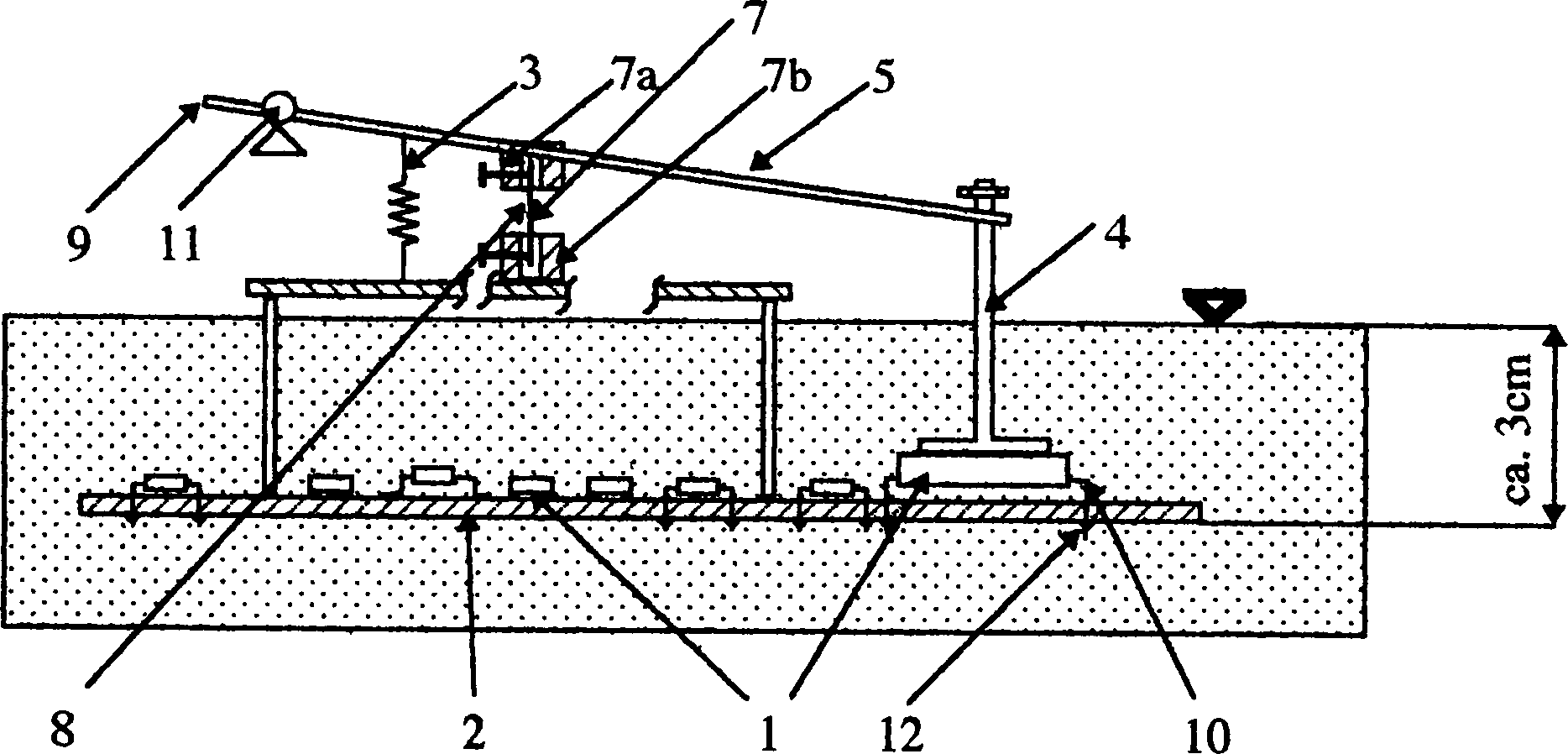
In
Das Rückhalteelement
Um zu verhindern, daß die Federkraft
vor dem Aufschmelzen des Lotes des Bauelementes
Wird nun die Entlötvorrichtung mit der die Bauelemente
Wenn das Formteil aus schmelzbarem
Material
Bei diesem bekannten System wird
die Auslösetemperatur
und damit der Zeitpunkt des Abhebens des zu entlötenden Bauelementes
In
Um jegliches Ausüben einer Kraft durch das elastische
Element
Das Formteil aus schmelzbarem Material
besitzt eine Schmelztemperatur von ca. 50 bis 100° C, welche
oberhalb der Raumtemperatur und unterhalb des Schmelzpunktes des
Lotes der Bauelemente
Dieser Zustand ist in
Mit der erfindungsgemäßen Vorrichtung
wird der Abhebezeitpunkt eines zu entlötenden Bauelementes
Claims (10)
Priority Applications (1)
| Application Number | Priority Date | Filing Date | Title |
|---|---|---|---|
| DE19617618A DE19617618B4 (en) | 1996-05-02 | 1996-05-02 | Method and device for unsoldering components, in particular electronic components |
Applications Claiming Priority (1)
| Application Number | Priority Date | Filing Date | Title |
|---|---|---|---|
| DE19617618A DE19617618B4 (en) | 1996-05-02 | 1996-05-02 | Method and device for unsoldering components, in particular electronic components |
Publications (2)
| Publication Number | Publication Date |
|---|---|
| DE19617618A1 DE19617618A1 (en) | 1997-11-06 |
| DE19617618B4 true DE19617618B4 (en) | 2004-07-22 |
Family
ID=7793121
Family Applications (1)
| Application Number | Title | Priority Date | Filing Date |
|---|---|---|---|
| DE19617618A Expired - Lifetime DE19617618B4 (en) | 1996-05-02 | 1996-05-02 | Method and device for unsoldering components, in particular electronic components |
Country Status (1)
| Country | Link |
|---|---|
| DE (1) | DE19617618B4 (en) |
Families Citing this family (1)
| Publication number | Priority date | Publication date | Assignee | Title |
|---|---|---|---|---|
| DE102021202737A1 (en) | 2021-03-22 | 2022-09-22 | Volkswagen Aktiengesellschaft | Method of connecting a heat-generating component to a cooling device |
Citations (5)
| Publication number | Priority date | Publication date | Assignee | Title |
|---|---|---|---|---|
| JPH01129493A (en) * | 1987-11-16 | 1989-05-22 | Hitachi Ltd | Method and device for removing component mounted on surface part |
| JPH01294493A (en) * | 1988-05-20 | 1989-11-28 | Tokico Ltd | Oil feeding device |
| DE4338094A1 (en) * | 1993-11-08 | 1995-05-11 | Helmut W Leicht | Device for moving an object by means of thermal shape or volume change |
| DE4211241C2 (en) * | 1992-04-03 | 1995-12-14 | Helmut Walter Leicht | Process for desoldering components, in particular SMD components |
| DE19510985A1 (en) * | 1995-03-24 | 1996-09-26 | Asscon Systech Elektronik Gmbh | Device for unsoldering components, in particular electronic components |
-
1996
- 1996-05-02 DE DE19617618A patent/DE19617618B4/en not_active Expired - Lifetime
Patent Citations (5)
| Publication number | Priority date | Publication date | Assignee | Title |
|---|---|---|---|---|
| JPH01129493A (en) * | 1987-11-16 | 1989-05-22 | Hitachi Ltd | Method and device for removing component mounted on surface part |
| JPH01294493A (en) * | 1988-05-20 | 1989-11-28 | Tokico Ltd | Oil feeding device |
| DE4211241C2 (en) * | 1992-04-03 | 1995-12-14 | Helmut Walter Leicht | Process for desoldering components, in particular SMD components |
| DE4338094A1 (en) * | 1993-11-08 | 1995-05-11 | Helmut W Leicht | Device for moving an object by means of thermal shape or volume change |
| DE19510985A1 (en) * | 1995-03-24 | 1996-09-26 | Asscon Systech Elektronik Gmbh | Device for unsoldering components, in particular electronic components |
Also Published As
| Publication number | Publication date |
|---|---|
| DE19617618A1 (en) | 1997-11-06 |
Similar Documents
| Publication | Publication Date | Title |
|---|---|---|
| EP0618035B1 (en) | Solder/desolder device for integrated circuits | |
| DE2852753C3 (en) | Method for fastening components with flat connection contacts on a printed circuit board and template for carrying out the method | |
| DE102008053182B4 (en) | Device with an electronic assembly with thermal fuse | |
| DE102022109905A1 (en) | Method and apparatus for soldering an electronic component to a circuit board, computer program product and computer-readable medium | |
| DE102010002150A1 (en) | Solder mask for wave soldering and method for selectively soldering individual components of a printed circuit board in a wave soldering machine | |
| EP0420050B1 (en) | Method of soldering of components on circuit boards | |
| DE10042661A1 (en) | Mounting method for semiconductor chip, involves deflecting gripper relative to bonding head so as to lower chip at soldering portion of substrate and then raising it by preset distance before being let go by gripper | |
| DE4330467C1 (en) | Method for soldering surface-mounted electronic components (SMDs) onto printed circuit boards | |
| DE19617618B4 (en) | Method and device for unsoldering components, in particular electronic components | |
| DE69126725T2 (en) | Localized soldering station | |
| DE10124328A1 (en) | Device for unsoldering electronic component has heat source at distance from bearer's component side so solder joint heating to melting point takes place indirectly by heating component | |
| DE4338094C2 (en) | Device for desoldering an object by means of thermal volume change | |
| DE102006048448A1 (en) | Solder connection making method for process and automation engineering, involves approximating sensor unit to casing such that solder is made between sensor unit and casing and solder is melted | |
| EP0815713B1 (en) | Device for separating components from a substrate, in particular for unsoldering electronic components | |
| DE19826520C1 (en) | Process for controlling heat transfer to a workpiece in vapor phase soldering | |
| DE10020820A1 (en) | Laser welder especially suitable for low absorption materials, includes intensifier causing chemical or physical action increasing thermal energy delivery to weld | |
| DE69817932T2 (en) | Method for connecting electronic components on a substrate | |
| EP0378113B1 (en) | Soldering device with at least one bow-shaped electrode | |
| DE102006035528A1 (en) | Method and wave soldering system for soldering components on the top and bottom of a printed circuit board | |
| DE2258098A1 (en) | DEVICE FOR SOLDERING AND REMOVING COMPONENTS ON EQUIPPED CIRCUIT BOARDS | |
| DE19602312C2 (en) | Method for connecting objects with metallic materials and device therefor | |
| DE2119402A1 (en) | Plumbing device | |
| DE10024676C2 (en) | Method for determining flow conditions and test board | |
| DE102007021269A1 (en) | Surface mount device repair soldering head and method of operation | |
| DE102005018539B4 (en) | Tool for performing a heat treatment |
Legal Events
| Date | Code | Title | Description |
|---|---|---|---|
| 8110 | Request for examination paragraph 44 | ||
| 8364 | No opposition during term of opposition | ||
| R071 | Expiry of right |