TECHNISCHES GEBIETTECHNICAL AREA
Die vorliegende Erfindung betrifft ein aufgerautes, vernickeltes Blech mit einer aufgerauten Nickelschicht als äußerste Oberflächenschicht.The present invention relates to a roughened, nickel-plated sheet metal with a roughened nickel layer as the outermost surface layer.
STAND DER TECHNIKSTATE OF THE ART
Konventionell wird als ein Bauteil, das die Batterie bildet, oder ein Bauteil, das die elektronikbezogene Ausrüstung bildet, ein vernickeltes Stahlblech verwendet. Wenn ein solches vernickeltes Stahlblech mit anderen Bauteilen verbunden wird, ist zur Verbesserung der Haftung ein Verfahren zur Steuerung der Oberflächenstruktur des vernickelten Stahlblechs bekannt.Conventionally, as a component constituting the battery or a component constituting the electronic-related equipment, a nickel-plated steel sheet is used. When such a nickel-plated steel sheet is bonded to other members, there is known a method of controlling the surface structure of the nickel-plated steel sheet in order to improve the adhesion.
Patentdokument 1 offenbart beispielsweise ein oberflächenbehandeltes Stahlblech, das durch Ausbilden einer Nickelplattierungsschicht mit einer Mikrostruktur, die auf eine Partikeldichte von 2 bis 500 Partikel/µm2 und einen durchschnittlichen Partikeldurchmesser von 0,05 bis 0,7 µm eingestellt ist, auf einem Stahlblech gebildet wird.For example, Patent Document 1 discloses a surface-treated steel sheet formed by forming a nickel plating layer having a microstructure adjusted to a particle density of 2 to 500 particles / µm 2 and an average particle diameter of 0.05 to 0.7 µm on a steel sheet .
PATENTDOKUMENTPATENT DOCUMENT
Patentdokument 1: Japanisches Patent Nr. 5885345 Patent Document 1: Japanese Patent No. 5885345
ZUSAMMENFASSUNG DER ERFINDUNGSUMMARY OF THE INVENTION
VON DER ERFINDUNG ZU LÖSENDES PROBLEMPROBLEM TO BE SOLVED BY THE INVENTION
Bei dem im Patentdokument 1 offenbarten oberflächenbehandelten Stahlblech kann jedoch je nach Art des Bauteils, das mit dem oberflächenbehandelten Stahlblech verbunden werden soll, und dem Verbindungsverfahren die Haftfähigkeit zu anderen Bauteilen unzureichend sein, und es wurde eine weitere Verbesserung der Haftfähigkeit gefordert.In the surface-treated steel sheet disclosed in Patent Document 1, however, depending on the kind of the component to be bonded to the surface-treated steel sheet and the bonding method, the adhesiveness to other components may be insufficient, and further improvement of the adhesiveness has been demanded.
Andererseits ist auch ein Verfahren denkbar, bei dem eine Nickelplattierungsschicht durch aufrauendes Plattieren gebildet wird, um die Haftung mit anderen Bauteilen zu verbessern. Bei den Untersuchungen der Erfinder der vorliegenden Erfindung hat sich jedoch herausgestellt, dass das Problem besteht, dass die Haftung der aufgerauten Plattierungsschicht, die selber durch aufrauendes Plattieren auf dem Grundmaterial gebildet wird, herabgesetzt ist und somit die Zuverlässigkeit in einigen Fällen herabgesetzt ist.On the other hand, a method is also conceivable in which a nickel plating layer is formed by roughening plating in order to improve the adhesion with other components. However, the investigations by the inventors of the present invention have found that there is a problem that the adhesion of the roughened plating layer, which is itself formed by roughening plating on the base material, is lowered and thus the reliability is lowered in some cases.
Es ist eine Aufgabe der vorliegenden Erfindung, ein aufgerautes, vernickeltes Blech bereitzustellen, das eine ausgezeichnete Haftung an anderen Bauteilen aufweist und gleichzeitig eine gute Haftung einer Plattierungsschicht an einem Grundmaterial beibehält.It is an object of the present invention to provide a roughened nickel-plated sheet which has excellent adhesion to other components while maintaining good adhesion of a cladding layer to a base material.
MITTEL ZUR LÖSUNG DES PROBLEMSMEANS TO SOLVE THE PROBLEM
Als Ergebnis intensiver Studien zur Erreichung der obigen Aufgabe haben die Erfinder der vorliegenden Erfindung herausgefunden, dass es durch die Steuerung der Helligkeit und des Glanzgrades von 85° der Oberfläche der aufgerauten Nickelschicht auf einen bestimmten Bereich möglich ist, ein aufgerautes vernickeltes Blech zu erhalten, das eine ausgezeichnete Haftung zu anderen Bauteilen aufweist, während eine gute Haftung der Plattierungsschicht zum Grundmaterial beibehalten wird, wodurch die vorliegende Erfindung vervollständigt wird.As a result of intensive studies to achieve the above object, the inventors of the present invention have found that by controlling the brightness and gloss level of 85 ° of the surface of the roughened nickel layer to a certain area, it is possible to obtain a roughened nickel-plated sheet which exhibits excellent adhesion to other components while maintaining good adhesion of the clad layer to the base material, thereby completing the present invention.
Insbesondere wird gemäß der vorliegenden Erfindung ein aufgerautes, vernickeltes Blech, bzw. Nickel-plattiertes Blech, mit einer aufgerauten Nickelschicht als äußerste Oberflächenschicht auf mindestens einer Oberfläche eines Metallgrundmaterials bereitgestellt, wobei
die Helligkeit L* der Oberfläche der aufgerauten Nickelschicht 30 bis 50 beträgt,
der Glanzgrad von 85° der Oberfläche der aufgerauten Nickelschicht 1,5 bis 50 beträgt.In particular, according to the present invention, a roughened, nickel-plated sheet metal or nickel-plated sheet metal is provided with a roughened nickel layer as the outermost surface layer on at least one surface of a metal base material, wherein
the brightness L * of the surface of the roughened nickel layer is 30 to 50,
the gloss level of 85 ° of the surface of the roughened nickel layer is 1.5 to 50.
Bei dem aufgerauten, vernickelten Blech gemäß der vorliegenden Erfindung ist es bevorzugt, dass das Metallgrundmaterial ein Metallblech oder eine Metallfolie ist, das/die aus einer Art von reinem Metall, ausgewählt aus Fe, Cu, Al und Ni, hergestellt ist, oder ein Metallblech oder eine Metallfolie, das/die aus einer Legierung hergestellt ist, die eine Art, ausgewählt aus Fe, Cu, Al und Ni, enthält.In the roughened, nickel-plated sheet according to the present invention, it is preferable that the metal base material is a metal sheet or a metal foil made of a kind of pure metal, selected from Fe, Cu, Al and Ni, or a metal sheet or metal foil made of an alloy containing a kind selected from Fe, Cu, Al and Ni.
Bei dem aufgerauten vernickelten Blech gemäß der vorliegenden Erfindung ist es bevorzugt, dass das Metallgrundmaterial ein Stahlblech ist.In the roughened nickel-plated sheet according to the present invention, it is preferable that the metal base material is a steel sheet.
Bei dem aufgerauten vernickelten Blech gemäß der vorliegenden Erfindung ist es bevorzugt, dass die Dicke des Metallgrundmaterials 0,01 bis 2,0 mm beträgt.In the roughened nickel-plated sheet according to the present invention, it is preferable that the thickness of the metal base material is 0.01 to 2.0 mm.
Bei dem aufgerauten vernickelten Blech gemäß der vorliegenden Erfindung ist es bevorzugt, dass die Abscheidungsmenge der Vernickelung bzw. Nickelplattierung 5,0 bis 50,0 g/m2 beträgt.In the roughened nickel-plated sheet according to the present invention, it is preferable that the deposition amount of the nickel-plating is 5.0 to 50.0 g / m 2 .
Bei dem aufgerauten vernickelten Blech gemäß der vorliegenden Erfindung ist es bevorzugt, dass die aufgeraute Nickelschicht einen arithmetischen Mittelwert der Rauheit Ra von 0,1 bis 3,0 µm durch Lasermikroskopie aufweist und die aufgeraute Nickelschicht einen Zehn-Punkt-Mittelwert der Rauheit Rzjis von 2,0 bis 20,0 µm durch Lasermikroskopie aufweist.In the roughened nickel-plated sheet according to the present invention, it is preferable that the roughened nickel layer has an arithmetic mean roughness Ra of 0.1 to 3.0 µm by laser microscopy and the roughened nickel layer has a ten-point mean roughness Rz jis 2.0 to 20.0 µm by laser microscopy.
WIRKUNGEN DER ERFINDUNGEFFECTS OF THE INVENTION
Gemäß der vorliegenden Erfindung kann ein aufgerautes, vernickeltes Blech bereitgestellt werden, das eine hervorragende Haftung zu anderen Bauteilen aufweist und gleichzeitig eine gute Haftfähigkeit der Plattierungsschicht zum Grundmaterial beibehält.According to the present invention, there can be provided a roughened nickel-plated sheet which has excellent adhesion to other components while maintaining good adhesion of the clad layer to the base material.
FigurenlisteFigure list
-
1A ist ein Konfigurationsdiagramm eines aufgerauten, vernickelten Blechs gemäß der vorliegenden Ausführungsform. 1A Fig. 13 is a configuration diagram of a roughened nickel-plated sheet according to the present embodiment.
-
1B ist ein Konfigurationsdiagramm eines aufgerauten, vernickelten Blechs gemäß einer anderen Ausführungsform. 1B Fig. 13 is a configuration diagram of a roughened nickel-plated sheet according to another embodiment.
-
2 ist eine erste schematische Ansicht zur Erläuterung eines Beispiels für ein Verfahren zur Herstellung eines aufgerauten vernickelten Blechs gemäß der vorliegenden Ausführungsform. 2 Fig. 13 is a first schematic view for explaining an example of a method of manufacturing a roughened nickel-plated sheet according to the present embodiment.
-
3 ist eine zweite schematische Ansicht zur Erläuterung eines Beispiels für ein Verfahren zur Herstellung eines aufgerauten vernickelten Blechs gemäß der vorliegenden Ausführungsform. 3 Fig. 13 is a second schematic view for explaining an example of a method of manufacturing a roughened nickel-plated sheet according to the present embodiment.
-
4 ist eine dritte schematische Ansicht zur Erläuterung eines Beispiels für ein Verfahren zur Herstellung eines aufgerauten vernickelten Blechs gemäß der vorliegenden Ausführungsform. 4th Fig. 13 is a third schematic view for explaining an example of a method of manufacturing a roughened nickel-plated sheet according to the present embodiment.
-
5(A) und 5(B) sind Aufnahmen, die durch Betrachten einer Oberfläche eines aufgerauten, vernickelten Blechs von Beispiel 28 mit einem Rasterelektronenmikroskop (REM bzw. SEM) erhalten wurden, 5(C) und 5(D) sind Aufnahmen, die durch Betrachten eines Querschnitts eines aufgerauten, vernickelten Blechs von Beispiel 28 mit einem Rasterelektronenmikroskop (REM bzw. SEM) erhalten wurden. 5 (A) and 5 (B) are photographs obtained by observing a surface of a roughened, nickel-plated sheet of Example 28 with a scanning electron microscope (SEM or SEM), 5 (C) and 5 (D) are photographs obtained by observing a cross section of a roughened nickel-plated sheet of Example 28 with a scanning electron microscope (SEM or SEM).
-
6(A) und 6(B) sind Aufnahmen, die durch Betrachten einer Oberfläche eines aufgerauten vernickelten Blechs von Vergleichsbeispiel 5 mit einem Rasterelektronenmikroskop (REM) erhalten wurden, 6(C) und 6(D) sind Aufnahmen, die durch Betrachten eines Querschnitts eines aufgerauten vernickelten Blechs von Vergleichsbeispiel 5 mit einem Rasterelektronenmikroskop (REM) erhalten wurden. 6 (A) and 6 (B) are photographs obtained by observing a surface of a roughened nickel-plated sheet of Comparative Example 5 with a scanning electron microscope (SEM), 6 (C) and 6 (D) are photographs obtained by observing a cross section of a roughened nickel-plated sheet of Comparative Example 5 with a scanning electron microscope (SEM).
-
7(A) und 7(B) sind schematische Diagramme, die eine Ausführungsform einer aufgerauten Nickelschicht zeigen. 7 (A) and 7 (B) Fig. 13 are schematic diagrams showing an embodiment of a roughened nickel layer.
-
8(A) bis 8(C) sind schematische Diagramme, die eine Ausführungsform einer aufgerauten Nickelschicht zeigen. 8 (A) to 8 (C) Fig. 13 are schematic diagrams showing an embodiment of a roughened nickel layer.
-
9(A) bis 9(D) sind schematische Diagramme, die eine Ausführungsform einer aufgerauten Nickelschicht zeigen. 9 (A) to 9 (D) Fig. 13 are schematic diagrams showing an embodiment of a roughened nickel layer.
-
10(A) bis 10(D) sind schematische Diagramme, die eine Ausführungsform einer aufgerauten Nickelschicht zeigen. 10 (A) to 10 (D) Fig. 13 are schematic diagrams showing an embodiment of a roughened nickel layer.
-
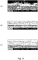
11(A) bis 11(C) sind Rasterelektronenmikroskopie (REM)-Aufnahmen eines Querschnitts einer aufgerauten Nickelschicht. 11 (A) to 11 (C) are scanning electron microscopy (SEM) images of a cross section of a roughened nickel layer.
-
12(A) bis 12(C) sind Rasterelektronenmikroskopie (REM)-Aufnahmen eines Querschnitts einer aufgerauten Nickelschicht. 12 (A) to 12 (C) are scanning electron microscopy (SEM) images of a cross section of a roughened nickel layer.
-
13(A) und 13(B) sind Rasterelektronenmikroskopie (REM)-Aufnahmen eines Querschnitts einer aufgerauten Nickelschicht. 13 (A) and 13 (B) are scanning electron microscopy (SEM) images of a cross section of a roughened nickel layer.
-
14(A) und 14(B) sind Rasterelektronenmikroskopie (REM)-Aufnahmen eines Querschnitts einer aufgerauten Nickelschicht. 14 (A) and 14 (B) are scanning electron microscopy (SEM) images of a cross section of a roughened nickel layer.
-
15 ist ein Diagramm zur Erläuterung eines Verfahrens zur Bestimmung einer Grenze zwischen einem Metallsubstrat und einer darunter liegenden Nickelschicht und einer Grenze zwischen einer darunter liegenden Nickelschicht und einer aufgerauten Nickelschicht in den Beispielen und Vergleichsbeispielen. 15th Fig. 13 is a diagram for explaining a method of determining a boundary between a metal substrate and an underlying nickel layer and a boundary between an underlying nickel layer and a roughened nickel layer in Examples and Comparative Examples.
BESCHREIBUNG DER AUSFÜHRUNGSFORMENDESCRIPTION OF THE EMBODIMENTS
1A ist ein Diagramm, das eine Konfiguration eines aufgerauten vernickelten Blechs 1 der vorliegenden Ausführungsform zeigt. Wie in 1A gezeigt, ist das aufgeraute, vernickelte Blech 1 der vorliegenden Ausführungsform mit einer aufgerauten Nickelschicht 12 als äußerste Oberflächenschicht auf einem Metallgrundmaterial 11 ausgebildet. In dem aufgerauten vernickelten Blech 1 gemäß der vorliegenden Ausführungsform hat die aufgeraute Nickelschicht 12 eine Helligkeit L* von 30 bis 50 und einen Glanzgrad von 85° von 3 bis 50. 1A Fig. 13 is a diagram showing a configuration of a roughened nickel-plated sheet 1 of the present embodiment shows. As in 1A shown is the roughened, nickel-plated sheet metal 1 of the present embodiment with a roughened nickel layer 12th as the outermost surface layer on a metal base material 11 educated. In the roughened nickel-plated sheet metal 1 according to the present embodiment has the roughened nickel layer 12th a brightness L * from 30 to 50 and a gloss level of 85 ° from 3 to 50.
In der vorliegenden Ausführungsform, wie sie in 1A gezeigt ist, ist das aufgeraute vernickelte Blech 1, bei dem die aufgeraute Nickelschicht 12 auf beiden Oberflächen des Metallgrundmaterials 11 ausgebildet ist, veranschaulicht, aber es ist nicht besonders auf eine solche Ausführungsform beschränkt, und beispielsweise kann die aufgeraute Nickelschicht 12 auf einer Oberfläche des Metallgrundmaterials 11 ausgebildet sein, wie bei dem in 1B gezeigten aufgerauten vernickelten Blech 1a.In the present embodiment, as shown in 1A shown is the roughened nickel-plated sheet 1 , in which the roughened nickel layer 12th on both surfaces of the metal base material 11 is formed is illustrated, but it is not particularly limited to such an embodiment, and for example, the roughened nickel layer may 12th on a surface of the metal base material 11 be designed as in the 1B shown roughened nickel-plated sheet metal 1a .
<Metallgrundmaterial 11><Metal Base Material 11>
Das Metallgrundmaterial 11 als Substrat des aufgerauten vernickelten Blechs 1 der vorliegenden Ausführungsform ist nicht besonders beschränkt, ein Metallblech oder eine Metallfolie aus einer Art von reinem Metall, ausgewählt aus Fe, Cu, Al und Ni, oder ein Metallblech oder eine Metallfolie aus einer Legierung, die eine Art, ausgewählt aus Fe, Cu, Al und Ni, enthält, insbesondere Stahlblech, Eisenblech, Edelstahlblech, Kupferblech, Aluminiumblech oder Nickelblech (diese können jedes der reinen Metalle und Legierungen sein, können eine Folie sein.) Unter ihnen wird, da die Plattierung auch mit einer relativ einfachen Vorbehandlung des Plattierungsverfahrens leicht durchführbar ist und es einfach ist, eine stark haftende aufgeraute Nickelschicht auf dem Metallgrundmaterial zu bilden, ein Stahlblech oder ein Kupferblech bevorzugt, insbesondere werden ein kohlenstoffarmer aluminiumberuhigter Stahl (Kohlenstoffgehalt von 0,01 bis 0,15 Gew.-%), besonders kohlenstoffarmer Stahl mit einem Kohlenstoffgehalt von 0,01 Gew.-% oder weniger (vorzugsweise einem Kohlenstoffgehalt von 0,003 Gew.-% oder weniger) oder alterungsbeständiger, besonders kohlenstoffarmer Stahl, der durch Zugabe von Ti, Nb und dergleichen zu einem besonders kohlenstoffarmen Stahl hergestellt wird, bevorzugt verwendet.The metal base material 11 as the substrate of the roughened nickel-plated sheet 1 The present embodiment is not particularly limited to a metal sheet or a metal foil made of one kind of pure metal selected from Fe, Cu, Al and Ni, or a metal sheet or a metal foil made of an alloy which is one kind selected from Fe, Cu, Al and Ni, particularly sheet steel, iron sheet, stainless steel sheet, copper sheet, aluminum sheet or nickel sheet (these can be any of the pure metals and alloys, can be a foil.) Among them, there is, as the plating also with a relatively simple pretreatment of the plating process is easy to carry out and it is easy to form a strongly adhering roughened nickel layer on the metal base material, a steel sheet or a copper sheet is preferred, in particular a low-carbon aluminum-killed steel (carbon content from 0.01 to 0.15% by weight), particularly low-carbon steel Steel with a carbon content of 0.01% by weight or less (preferably a carbon content t of 0.003 wt% or less) or aging-resistant high carbon steel made by adding Ti, Nb and the like to high carbon steel is preferably used.
In der vorliegenden Ausführungsform kann ein Stahlblech, Kupferblech, Aluminiumblech oder Nickelblech, das durch Warmwalzen eines dieser Bleche, saures Beizen des warmgewalzten Blechs zum Entfernen von Zunder (Oxidfilm) auf der Oberfläche und Kaltwalzen des gebeizten Blechs erhalten wird, als Substrat verwendet werden. Alternativ kann ein Blech verwendet werden, an dem nach der elektrolytischen Reinigung Glühen oder Walzen mit Tempern durchgeführt wird. In diesem Fall kann das Glühen ein kontinuierliches Glühen oder ein Kastenglühen sein, das nicht besonders begrenzt ist. Darüber hinaus kann als elektrolytische Folie, die durch das Elektroformungverfahren hergestellt wird, auch Kupferfolie, Nickelfolie, Eisenfolie oder ähnliches als Metallgrundmaterial verwendet werden.In the present embodiment, a steel sheet, copper sheet, aluminum sheet or nickel sheet obtained by hot rolling any of these sheets, acid pickling the hot rolled sheet to remove scale (oxide film) on the surface, and cold rolling the pickled sheet can be used as the substrate. Alternatively, a sheet metal can be used on which annealing or rolling with tempering is carried out after electrolytic cleaning. In this case, the annealing may be continuous annealing or box annealing, which is not particularly limited. In addition, as the electrolytic foil produced by the electroforming method, copper foil, nickel foil, iron foil or the like can also be used as a metal base material.
Im Übrigen ist es bei dem Metallgrundmaterial 11, wenn ein Metallgrundmaterial verwendet wird, bei dem ein passiver Film auf der Oberfläche gebildet wird, wie z.B. ein Edelstahlblech und ein Nickelblech, vor dem Plattieren von aufgerautem Nickel oder vor dem Plattierungsverfahren zur Bildung der darunter liegenden Metallplattierung bevorzugt, solche zu verwenden, die einer Schlagvernickelung („strike nickel plating“) unterzogen werden. Die Bedingungen der Schlagvernickelung sind nicht besonders begrenzt, und es können beispielsweise die folgenden Bedingungen gegeben sein. Unter den folgenden Bedingungen beträgt die Abscheidungsmenge des Nickels durch Schlagvernickelung normalerweise 0,08 bis 0,89 g/m2, aber bei der Bildung einer darunter liegenden Nickelschicht wird die Summe der Abscheidungsmenge des Nickels durch Schlagvernickelung und der Abscheidungsmenge des Nickels durch Vernickelung zur Bildung einer darunter liegenden Nickelschicht als die Abscheidungsmenge des Nickels durch die darunter liegende Nickelschicht gemessen.
- Badzusammensetzung: Nickelsulfat-Hexahydrat 100 bis 300 g/L, Schwefelsäure 10 bis 200 g/L
- pH-Wert: 1,0 oder weniger
- Badtemperatur: 40 bis 70°C
- Stromdichte: 5 bis 100 A/dm2
- Plattierungszeit: 3 bis 100 Sekunden
Incidentally, it is with the metal base material 11 , when using a metal base material in which a passive film is formed on the surface, such as a stainless steel sheet and a nickel sheet, before plating roughened nickel or before the plating process for forming the underlying metal plating, it is preferable to use those that have a Strike nickel plating. Impact nickel plating conditions are not particularly limited, and the following conditions may be established, for example. Under the following conditions, the deposition amount of nickel by impact nickel plating is normally 0.08 to 0.89 g / m 2 , but when an underlying nickel layer is formed, the sum of the deposition amount of nickel becomes through Impact nickel plating and the amount of deposition of nickel by nickel plating to form an underlying nickel layer are measured as the amount of deposition of nickel by the underlying nickel layer. - Bath composition: nickel sulfate hexahydrate 100 to 300 g / L, sulfuric acid 10 to 200 g / L
- pH value: 1.0 or less
- Bath temperature: 40 to 70 ° C
- Current density: 5 to 100 A / dm 2
- Plating time: 3 to 100 seconds
Die Dicke des Metallgrundmaterials 11 ist nicht besonders begrenzt, beträgt aber vorzugsweise 0,01 bis 2,0 mm, noch bevorzugter 0,025 bis 1,6 mm und noch bevorzugter 0,025 bis 0,3 mm. Ferner ist die Rauheit des Metallgrundmaterials 11 nicht besonders begrenzt, aber der arithmetische Mittelwert der Rauheit Ra im stiftförmigen Oberflächenrauhigkeitsmessgerät beträgt 0,05 bis 2,0 µm, bevorzugter 0,05 bis 0,9 µm und noch bevorzugter 0,05 bis 0,5 µm.The thickness of the metal base material 11 is not particularly limited, but is preferably 0.01 to 2.0 mm, more preferably 0.025 to 1.6 mm, and even more preferably 0.025 to 0.3 mm. Further is the roughness of the metal base material 11 not particularly limited, but the arithmetic mean value of the roughness Ra in the pen-shaped surface roughness meter is 0.05 to 2.0 µm, more preferably 0.05 to 0.9 µm, and still more preferably 0.05 to 0.5 µm.
<Aufgeraute Nickelschicht 12><Roughened nickel layer 12th >
Die auf der äußersten Oberfläche des aufgerauten, vernickelten Blechs 1 der vorliegenden Ausführungsform gebildete aufgeraute Nickelschicht 12 ist eine, bei der die Helligkeit L* der Oberfläche auf 30 bis 50 kontrolliert wird und ein Glanzgrad von 85° der Oberfläche auf 3 bis 50 kontrolliert wird. Gemäß der vorliegenden Ausführungsform kann durch Kontrolle der Helligkeit L* und des Glanzgrades von 85° der Oberflächen der aufgerauten Nickelschicht 12 innerhalb der obigen Bereiche das aufgeraute, vernickelte Blech 1 als eines hergestellt werden, das eine ausgezeichnete Haftung an anderen Bauteilen aufweist, während eine gute Haftung der aufgerauten Nickelschicht 12 an dem Metallgrundmaterial 11 beibehalten wird.The ones on the outermost surface of the roughened, nickel-plated sheet metal 1 the roughened nickel layer formed in the present embodiment 12th is one in which the brightness L * of the surface is controlled to 30 to 50 and a gloss level of 85 ° of the surface is controlled to 3 to 50. According to the present embodiment, by controlling the brightness L * and the gloss level of 85 ° of the surfaces of the roughened nickel layer 12th the roughened, nickel-plated sheet metal within the above ranges 1 as one that has excellent adhesion to other components while having good adhesion of the roughened nickel layer 12th on the metal base material 11 is retained.
Insbesondere haben die Erfinder der vorliegenden Erfindung als Ergebnis intensiver Untersuchungen der Erfinder der vorliegenden Erfindung des Zusammenhangs zwischen der Helligkeit L* und dem Glanzgrad von 85° der Oberfläche der aufgerauten Nickelschicht 12 und der Haftfähigkeit der aufgerauten Nickelschicht 12 an dem Metallgrundmaterial 11 und der Haftfähigkeit der aufgerauten Nickelschicht 12 an anderen Bauteilen herausgefunden, dass durch Einstellen der Helligkeit L* und des Glanzgrades von 85° der Oberfläche der aufgerauten Nickelschicht 12 auf die obigen Bereiche das aufgeraute vernickelte Blech 1 eine ausgezeichnete Haftfähigkeit an anderen Bauteilen aufweisen kann, während die Haftfähigkeit der aufgerauten Nickelschicht 12 gut beibehalten wird, und die vorliegende Erfindung wurde abgeschlossen.In particular, as a result of intensive studies by the inventors of the present invention, the present inventors found the relationship between the lightness L * and the degree of gloss of 85 ° of the surface of the roughened nickel layer 12th and the adhesiveness of the roughened nickel layer 12th on the metal base material 11 and the adhesiveness of the roughened nickel layer 12th found on other components that by setting the brightness L * and the degree of gloss of 85 ° of the surface of the roughened nickel layer 12th the roughened nickel-plated sheet metal on the above areas 1 can have excellent adhesion to other components, while the adhesion of the roughened nickel layer 12th is well maintained, and the present invention has been completed.
Hier wird gemäß der vorliegenden Ausführungsform neben der hervorragenden Haftung zu anderen Bauteilen auch auf die Haftfähigkeit der aufgerauten Nickelschicht 12 zum Metallgrundmaterial 11 geachtet, und zwar aus folgendem Grund. Das heißt, dass durch die Bildung der aufgerauten Nickelschicht 12, selbst wenn es möglich ist, eine ausgezeichnete Haftfähigkeit zu anderen Bauteilen zu zeigen, wenn die aufgeraute Nickelschicht 12 leicht vom Metallgrundmaterial 11 abfällt, aufgrund dessen, dass die aufgeraute Nickelschicht 12 abfällt, der Effekt durch die Bildung der aufgerauten Nickelschicht 12 unzureichend wird, d.h. der Effekt, bei dem es möglich ist, eine ausgezeichnete Haftfähigkeit zu anderen Bauteilen zu zeigen, wird unzureichend. Daher haben die Erfinder der vorliegenden Erfindung unter diesem Gesichtspunkt der Haftung der aufgerauten Nickelschicht 12 an dem Metallgrundmaterial 11 Aufmerksamkeit geschenkt und diese verbessert.According to the present embodiment, in addition to the excellent adhesion to other components, the adhesion of the roughened nickel layer is also important 12th to the metal base material 11 respected for the following reason. That is, through the formation of the roughened nickel layer 12th even if it is possible to exhibit excellent adhesiveness to other components when the roughened nickel layer 12th slightly from the metal base material 11 falls off, due to the fact that the roughened nickel layer 12th falls off, the effect due to the formation of the roughened nickel layer 12th becomes insufficient, that is, the effect in which it is possible to exhibit excellent adhesiveness to other components becomes insufficient. Therefore, from this point of view, the inventors of the present invention have the adhesion of the roughened nickel layer 12th on the metal base material 11 Paying attention and improving it.
Darüber hinaus werden, wenn die Haftung der aufgerauten Nickelschicht 12 auf dem Metallgrundmaterial 11 unzureichend ist, bei der Herstellung des aufgerauten vernickelten Blechs 1 der vorliegenden Ausführungsform die Plattierungsfilmreste (Ni-Pulver) aufgrund des Abfallens der aufgerauten Nickelschicht 12 in der Fertigungslinie vermischt, zusätzlich dazu, dass sie eine Verunreinigung oder einen Ausfall der Fertigungslinie verursachen können, und es gibt einen Fall, in dem Produktfehler aufgrund der in der Fertigungslinie verbleibenden Plattierungsfilmreste verursacht werden. Außerdem verursacht die Verwendung des aufgerauten, vernickelten Blechs 1 der vorliegenden Ausführungsform, selbst wenn es tatsächlich zu Produkten oder Teilen verarbeitet wird, in ähnlicher Weise eine Verunreinigung oder einen Ausfall der Fertigungslinie, und es besteht die Möglichkeit, dass es Defekte in Bezug auf die Qualität oder Funktion des Endprodukts verursacht. Daher haben die Erfinder der vorliegenden Erfindung auch unter diesem Gesichtspunkt auf die Bedeutung der Haftung der aufgerauten Nickelschicht 12 auf dem Metallgrundmaterial 11 geachtet und diese verbessert.In addition, when the adhesion of the roughened nickel layer 12th on the metal base material 11 is insufficient in the manufacture of the roughened nickel-plated sheet 1 In the present embodiment, the plating film residue (Ni powder) due to the falling off of the roughened nickel layer 12th mixed in the production line, in addition to causing contamination or breakdown of the production line, and there is a case where product defects are caused due to the cladding film residue left on the production line. In addition, the use of the roughened, nickel-plated sheet metal causes 1 According to the present embodiment, similarly, even if it is actually made into products or parts, contamination or failure of the production line, and there is a possibility that it may cause defects in the quality or function of the final product. Therefore, the inventors of the present invention paid attention to the importance of the adhesion of the roughened nickel layer from this point of view as well 12th on the metal base material 11 respected and improved it.
Die Helligkeit der Oberfläche der aufgerauten Nickelschicht 12 liegt bei einem Wert von L* zwischen 30 und 50, vorzugsweise zwischen 30 und 48, noch bevorzugter zwischen 30 und 45 und noch bevorzugter zwischen 35 und 45. Unter dem Gesichtspunkt der Betonung der Produktionseffizienz und der Produktionskosten ist es bevorzugt, dass die Helligkeit der Oberfläche der aufgerauten Nickelschicht 12 36 bis 48 beträgt. Wenn der Wert der Helligkeit L* zu klein ist, wird die Haftung der aufgerauten Nickelschicht 12 auf dem Metallgrundmaterial 11 schlechter, während, wenn der Wert der Helligkeit L* zu groß ist, die Haftung auf anderen Bauteilen schlechter wird. Es ist zu beachten, dass die Helligkeit L* der Oberfläche der aufgerauten Nickelschicht 12 mit einem Spektralfotometer nach der SCE-Methode (Methode der Entfernung von spiegelndem reflektierten Licht, „specular reflected light removing method“) gemäß JIS Z8722 gemessen werden kann.The brightness of the surface of the roughened nickel layer 12th is at a value of L * between 30 and 50, preferably between 30 and 48, more preferably between 30 and 45, and still more preferably between 35 and 45. From the viewpoint of emphasizing production efficiency and production cost it is preferable that the brightness of the surface of the roughened nickel layer 12th 36 to 48. If the value of the lightness L * is too small, the adhesion of the roughened nickel layer will decrease 12th on the metal base material 11 worse, while if the value of the brightness L * is too large, the adhesion to other components becomes worse. It should be noted that the lightness L * of the surface of the roughened nickel layer 12th can be measured with a spectrophotometer according to the SCE method (specular reflected light removing method) according to JIS Z8722.
Der Glanzgrad („glossiness“) von 85° der Oberfläche der aufgerauten Nickelschicht 12 beträgt 1,5 bis 50, vorzugsweise 1,5 bis 35 und besonders bevorzugt 2 bis 30. Unter dem Gesichtspunkt der Betonung der Produktionseffizienz und der Produktionskosten beträgt der Glanzgrad von 85° der Oberfläche der aufgerauten Nickelschicht 12 vorzugsweise 15 bis 50. Wenn der Glanzgrad von 85° zu klein ist, wird die Haftung der aufgerauten Nickelschicht 12 auf dem Metallgrundmaterial 11 schlechter. Wenn der Glanzgrad zu groß ist, wird die Haftung zu anderen Bauteilen schlechter. Es ist zu beachten, dass der Glanzgrad von 85° der Oberfläche der aufgerauten Nickelschicht 12 durch Messung des Spiegelglanzes („specular gloss“) von 85° mit einem Glanzgradmesser gemäß JIS Z8741 bestimmt werden kann. Übrigens ist der Glanzgrad von 60° der aufgerauten Nickelschicht 12, die auf der äußersten Oberfläche des aufgerauten vernickelten Blechs 1 der vorliegenden Ausführungsform ausgebildet ist, normalerweise 10 oder weniger.The “glossiness” of 85 ° of the surface of the roughened nickel layer 12th is 1.5 to 50, preferably 1.5 to 35, and particularly preferably 2 to 30. From the viewpoint of emphasizing production efficiency and production cost, the degree of gloss is 85 ° of the surface of the roughened nickel layer 12th preferably 15 to 50. If the gloss level of 85 ° is too small, the adhesion of the roughened nickel layer will decrease 12th on the metal base material 11 worse. If the gloss level is too high, the adhesion to other components will be poorer. It should be noted that the gloss level of 85 ° of the surface of the roughened nickel layer 12th can be determined by measuring the specular gloss of 85 ° with a gloss meter according to JIS Z8741. Incidentally, the gloss level of the roughened nickel layer is 60 ° 12th on the outermost surface of the roughened nickel-plated sheet 1 of the present embodiment is typically 10 or less.
Obwohl der Farbwert a*, b* der Oberfläche der aufgerauten Nickelschicht 12 nicht besonders begrenzt ist, ist der Farbwert a* vorzugsweise 0,1 bis 3,0, bevorzugter 0,3 bis 1,5, und der Farbwert b* ist vorzugsweise 1,0 bis 8,0, bevorzugter 2,0 bis 7,0, unter dem Gesichtspunkt, dass die Haftung der aufgerauten Nickelschicht 12 an dem Metallgrundmaterial 11 und die Haftung der aufgerauten Nickelschicht 12 an anderen Bauteilen weiter verbessert werden kann.Although the color value a *, b * of the surface of the roughened nickel layer 12th is not particularly limited, the color value a * is preferably 0.1 to 3.0, more preferably 0.3 to 1.5, and the color value b * is preferably 1.0 to 8.0, more preferably 2.0 to 7, 0, from the viewpoint that the adhesion of the roughened nickel layer 12th on the metal base material 11 and the adhesion of the roughened nickel layer 12th can be further improved on other components.
Die aufgeraute Nickelschicht 12 kann die Helligkeit L* der Oberfläche und den Glanzgrad von 85° der Oberfläche innerhalb der obigen Bereiche haben, aber der arithmetische Mittelwert der Rauheit Ra ist vorzugsweise 0,1 bis 3 µm, unter dem Gesichtspunkt der Verbesserung der Haftung der aufgerauten Nickelschicht 12 an anderen Bauteilen ist der arithmetische Mittelwert der Rauheit Ra bevorzugter 0,18 µm oder mehr, noch bevorzugter 0,3 µm oder mehr, und unter dem Gesichtspunkt der Verbesserung der Haftung (Plattierungshaftung) der aufgerauten Nickelschicht 12 an dem Metallgrundmaterial 11 ist der arithmetische Mittelwert der Rauheit Ra bevorzugter 1,8 µm oder weniger, noch bevorzugter 1,6 µm oder weniger, noch bevorzugter 1,3 µm oder weniger. Unter dem Gesichtspunkt der Betonung der Produktionseffizienz und der Produktionskosten beträgt der arithmetische Mittelwert der Rauheit Ra außerdem vorzugsweise 0,18 bis 0,5 µm, noch bevorzugter 0,18 bis 0,49 µm. Die aufgeraute Nickelschicht 12 hat vorzugsweise einen Zehn-Punkt-Mittelwert der Rauheit Rzjis von 2,0 bis 20,0 µm, unter dem Gesichtspunkt der weiteren Verbesserung der Haftung der aufgerauten Nickelschicht 12 an anderen Bauteilen ist der Zehn-Punkt-Mittelwert der Rauheit Rzjis, bevorzugter 3 µm oder mehr, noch bevorzugter 4 µm oder mehr, und noch bevorzugter 5 µm oder mehr, und unter dem Gesichtspunkt der weiteren Verbesserung der Haftung (Plattierungshaftung) der aufgerauten Nickelschicht 12 an dem Metallgrundmaterial 11 ist der Zehn-Punkt-Mittelwert der Rauheit Rzjis bevorzugter 16 µm oder weniger, noch bevorzugter 14 µm oder weniger, und noch bevorzugter 12 µm oder weniger. Unter dem Gesichtspunkt der Betonung der Produktionseffizienz und der Produktionskosten ist es bevorzugt, dass der Zehn-Punkt-Mittelwert der Rauheit Rzjis 3,0 bis 7,0 µm beträgt. Es ist zu beachten, dass die maximale Höhenrauhigkeit Rz der aufgerauten Nickelschicht 12 nicht besonders begrenzt ist, aber vorzugsweise 2,5 bis 25,0 µm, bevorzugter 2,5 bis 20,0 µm und noch bevorzugter 3,5 bis 18,0 µm beträgt. Die Oberflächenrauhigkeiten Ra, Rzjis und Rz werden vorzugsweise mittels Lasermikroskopie gemessen.The roughened nickel layer 12th may have the lightness L * of the surface and the degree of gloss of 85 ° of the surface within the above ranges, but the arithmetic mean roughness Ra is preferably 0.1 to 3 µm from the viewpoint of improving the adhesion of the roughened nickel layer 12th on other members, the arithmetic mean roughness Ra is more preferably 0.18 µm or more, more preferably 0.3 µm or more, and from the viewpoint of improving the adhesion (plating adhesion) of the roughened nickel layer 12th on the metal base material 11 The arithmetic mean roughness Ra is more preferably 1.8 µm or less, still more preferably 1.6 µm or less, still more preferably 1.3 µm or less. Also, from the viewpoint of emphasizing production efficiency and production cost, the arithmetic mean roughness Ra is preferably 0.18 to 0.5 µm, more preferably 0.18 to 0.49 µm. The roughened nickel layer 12th preferably has a ten-point mean roughness Rz jis of 2.0 to 20.0 µm from the viewpoint of further improving the adhesion of the roughened nickel layer 12th on other members, the ten-point average roughness Rz is jis , more preferably 3 µm or more, still more preferably 4 µm or more, and still more preferably 5 µm or more, and from the viewpoint of further improving the adhesion (plating adhesion) of the roughened Nickel layer 12th on the metal base material 11 the ten-point mean roughness value Rz jis is more preferably 16 µm or less, more preferably 14 µm or less, and still more preferably 12 µm or less. From the viewpoint of emphasizing production efficiency and production cost, it is preferable that the ten-point mean value of the roughness Rz jis is 3.0 to 7.0 µm. It should be noted that the maximum height roughness Rz of the roughened nickel layer 12th is not particularly limited, but is preferably 2.5 to 25.0 µm, more preferably 2.5 to 20.0 µm, and still more preferably 3.5 to 18.0 µm. The surface roughness Ra, Rz jis and Rz are preferably measured by means of laser microscopy.
Die Abscheidungsmenge der aufgerauten Nickelschicht 12 im aufgerauten vernickelten Blech 1 der vorliegenden Ausführungsform ist nicht besonders begrenzt, beträgt aber vorzugsweise 1,34 bis 45,0 g/m2, und unter dem Gesichtspunkt der weiteren Verbesserung der Haftung (Plattierungshaftung) der aufgerauten Nickelschicht 12 beträgt die Abscheidungsmenge der aufgerauten Nickelschicht 12 bevorzugter 2,67 g/m2 oder mehr, noch bevorzugter 5 g/m2 oder mehr, und unter dem Gesichtspunkt der weiteren Verbesserung der Haftung der aufgerauten Nickelschicht 12 an anderen Bauteilen beträgt die Abscheidungsmenge der aufgerauten Nickelschicht 12 bevorzugter 38,0 g/m2 oder weniger, noch bevorzugter 32,0 g/m2 oder weniger, und noch bevorzugter 31 g/m2 oder weniger. Die Abscheidungsmenge der aufgerauten Nickelschicht 12 kann durch Messung der Gesamtnickelmenge des aufgerauten, vernickelten Blechs 1 unter Verwendung eines Fluoreszenz-Röntgengeräts ermittelt werden. Übrigens, wenn eine darunter liegende Metallplattierungsschicht 13 aus Nickel, die später beschrieben wird, gebildet wird, kann sie nach der Messung der Gesamtmenge an Nickel unter Verwendung eines Fluoreszenz-Röntgengeräts für das aufgeraute, vernickelte Blech 1 bestimmt werden, indem die Menge an Nickel, die der darunter liegenden Metallplattierungsschicht 13 entspricht, von der Gesamtmenge an Nickel abgezogen wird. Die Menge an Nickel, die der darunter liegenden Metallplattierungsschicht 13 entspricht, kann beispielsweise durch ein Verfahren zur Messung der Dicke der darunter liegenden Metallplattierungsschicht 13, indem das aufgeraute, vernickelte Blech 1 geschnitten und der Querschnitt mit einem Rasterelektronenmikroskop (REM bzw. SEM) beobachtet wird, und dann die Menge an Nickel bestimmt wird, die aus der Dicke der darunter liegenden Metallplattierungsschicht 13 umgewandelt wird; ein Verfahren zum Messen der Nickelmenge auf dem Metallgrundmaterial 11 zum Zeitpunkt der Bildung der darunter liegenden Metallplattierungsschicht 13 unter Verwendung eines Fluoreszenz-Röntgengeräts; ein Verfahren zum Bestimmen der aus der Coulomb-Menge berechneten Menge der galvanischen Abscheidung beim Bilden der darunter liegenden Metallplattierungsschicht 13 durch Plattieren auf dem Metallgrundmaterial 11 und dergleichen gemessen werden.The amount of deposition of the roughened nickel layer 12th in roughened nickel-plated sheet metal 1 of the present embodiment is not particularly limited, but is preferably 1.34 to 45.0 g / m 2 , and from the viewpoint of further improving the adhesion (plating adhesion) of the roughened nickel layer 12th is the amount of deposition of the roughened nickel layer 12th more preferably 2.67 g / m 2 or more, still more preferably 5 g / m 2 or more, and from the viewpoint of further improving the adhesion of the roughened nickel layer 12th on other components the amount of deposition is the roughened nickel layer 12th more preferably 38.0 g / m 2 or less, still more preferably 32.0 g / m 2 or less, and even more preferably 31 g / m 2 or less. The amount of deposition of the roughened nickel layer 12th can by measuring the total amount of nickel on the roughened, nickel-plated sheet 1 can be determined using a fluorescence x-ray machine. Incidentally, if an underlying metal plating layer 13th formed from nickel, which will be described later, after measuring the total amount of nickel using a fluorescent X-ray apparatus for the roughened nickel-plated sheet 1 can be determined by the amount of nickel present in the underlying metal plating layer 13th is deducted from the total amount of nickel. The amount of nickel contained in the underlying metal plating layer 13th for example, by a method of measuring the thickness of the underlying metal plating layer 13th by removing the roughened, nickel-plated sheet metal 1 cut and the cross section is observed with a scanning electron microscope (SEM or SEM), and then the amount of nickel is determined from the thickness of the underlying metal plating layer 13th is converted; a method of measuring the amount of nickel on the metal base material 11 at the time the underlying metal plating layer was formed 13th using a fluorescence x-ray machine; a method of determining the amount of electrodeposition calculated from the Coulomb amount in forming the underlying metal plating layer 13th by plating on the metal base material 11 and the like can be measured.
In der vorliegenden Ausführungsform ist das Verfahren zum Einstellen der Helligkeit L* und des Glanzgrades von 85° der Oberfläche der aufgerauten Nickelschicht 12 in den obigen Bereichen nicht besonders begrenzt, aber ein Verfahren zum Bilden der aufgerauten Nickelschicht 12 durch das unten beschriebene Verfahren oder dergleichen ist beispielhaft.In the present embodiment, the method of adjusting the lightness is L * and the degree of gloss of 85 ° of the surface of the roughened nickel layer 12th not particularly limited in the above ranges, but a method for forming the roughened nickel layer 12th by the method described below or the like is exemplary.
Ein Beispiel für ein Verfahren zur Bildung der aufgerauten Nickelschicht 12 wird im Folgenden unter Bezugnahme auf 2 bis 4 beschrieben. Zunächst wird, wie in 2 gezeigt, unter dem Gesichtspunkt der weiteren Verbesserung der Haftung zwischen dem Metallgrundmaterial 11 und der aufgerauten Nickelschicht 12 und der Verleihung von Korrosionsbeständigkeit entsprechend der Anwendung eine darunter liegende Metallplattierungsschicht 13 auf dem Metallgrundmaterial 11 nach Bedarf gebildet. Obwohl die aufgeraute Nickelschicht 12 direkt auf dem Metallgrundmaterial 11 gebildet werden kann, ohne die darunter liegende Metallplattierungsschicht 13 zu bilden, wird als nächstes eine Plattierung von aufgerautem Nickel bzw. eine aufrauende Vernickelung („roughened nickel plating“) durchgeführt, um die Nickelkörner 121 auf dem Metallgrundmaterial 11 in einem agglomerierten Zustand abzuscheiden, wie in 3 gezeigt. Als nächstes wird, wie in 4 gezeigt, eine abdeckende Vernickelung bzw. Plattierung von bedeckendem Nickel durchgeführt, um die Nickelkörner 121 mit dem Nickelfilm 122 zu Plattieren, wodurch die aufgeraute Nickelschicht 12 auf dem Metallgrundmaterial 11 gebildet wird, wobei die darunter liegende Metallplattierungsschicht 13, wie erforderlich, dazwischen angeordnet gebildet wird.An example of a method of forming the roughened nickel layer 12th will be referred to below with reference to 2 to 4th described. First, as in 2 shown from the viewpoint of further improving the adhesion between the metal base material 11 and the roughened nickel layer 12th and imparting corrosion resistance according to the application, an underlying metal plating layer 13th on the metal base material 11 formed as required. Although the roughened nickel layer 12th directly on the metal base material 11 can be formed without the underlying metal plating layer 13th To form, roughened nickel plating ("roughened nickel plating") is carried out next to the nickel grains 121 on the metal base material 11 to be deposited in an agglomerated state, as in FIG 3 shown. Next, as in 4th As shown, blanket nickel plating is performed around the nickel grains 121 with the nickel film 122 to plating, removing the roughened nickel layer 12th on the metal base material 11 is formed with the underlying metal plating layer 13th as required, is formed interposed therebetween.
Die Bedingung der Plattierung von aufgerautem Nickel zur Abscheidung der Nickelkörner 121 in einem agglomerierten Zustand ist nicht besonders begrenzt, aber unter dem Gesichtspunkt, dass die Helligkeit L* und der Glanzgrad von 85° der Oberflächen der aufgerauten Nickelschichten 12 innerhalb der obigen Bereiche geeignet gesteuert werden können, ist ein Verfahren durch elektrolytische Plattierung unter Verwendung eines Plattierungsbades, das Nickelsulfat-Hexahydrat in einer Konzentration von 10 bis 100 g/L und Ammoniumsulfat in einer Konzentration von 1 bis 100 g/L enthält, bevorzugt. Die Konzentration von Nickelsulfat-Hexahydrat im verwendeten Plattierungsbad liegt vorzugsweise bei 10 bis 70 g/L, noch bevorzugter bei 10 bis 50 g/L und noch bevorzugter bei 15 bis 25 g/L. Es ist zu beachten, dass als Nickelionenquelle Nickelchlorid-Hexahydrat eingesetzt werden kann oder Nickelchlorid-Hexahydrat und Nickelsulfat-Hexahydrat in Kombination verwendet werden können. Wenn Nickelchlorid-Hexahydrat verwendet wird, wird die Konzentration von Nickelchlorid-Hexahydrat vorzugsweise auf 1 bis 40 g/L eingestellt. Wenn jedoch die Nickelionenkonzentration und die Chloridionenkonzentration ansteigen, wird es schwierig, eine geeignete aufgeraute Form mit einer vorbestimmten Helligkeit und einem vorbestimmten Glanzgrad zu erhalten, und daher sollte bei der Kombination mit Nickelsulfat-Hexahydrat und Ammoniumchlorid vorsichtig vorgegangen werden. Wenn Ammoniumsulfat als Ammoniakquelle in der Plattierungslösung verwendet wird, beträgt die Konzentration von Ammoniumsulfat im verwendeten Plattierungsbad außerdem vorzugsweise 10 bis 50 g/L, noch bevorzugter 10 bis 45 g/L und noch bevorzugter 15 bis 40 g/L. Es ist zu beachten, dass die Zugabe von Ammoniak in das Vernickelungsbad durch Zugabe von Ammoniakwasser oder durch Zugabe eines Salzes wie Ammoniumsulfat und Ammoniumchlorid erfolgen kann. Die Konzentration von Ammoniak im Plattierungsbad beträgt vorzugsweise 0,3 bis 30 g/L, bevorzugter 1 bis 20 g/L, noch bevorzugter 3 bis 15 g/L und besonders bevorzugt 3 bis 12 g/L.The condition of plating roughened nickel to deposit the nickel grains 121 in an agglomerated state is not particularly limited, but from the viewpoint that the lightness L * and the degree of gloss of 85 ° of the surfaces of the roughened nickel layers 12th can be appropriately controlled within the above ranges, an electrolytic plating method using a plating bath containing nickel sulfate hexahydrate in a concentration of 10 to 100 g / L and ammonium sulfate in a concentration of 1 to 100 g / L is preferred. The concentration of nickel sulfate hexahydrate in the plating bath used is preferably 10 to 70 g / L, more preferably 10 to 50 g / L, and even more preferably 15 to 25 g / L. It should be noted that nickel chloride hexahydrate can be used as the source of nickel ions, or nickel chloride hexahydrate and nickel sulfate hexahydrate can be used in combination. When nickel chloride hexahydrate is used, the concentration of nickel chloride hexahydrate is preferably adjusted to 1 to 40 g / L. However, if the nickel ion concentration and the chloride ion concentration increase, it becomes difficult to obtain a suitable roughened shape having a predetermined brightness and gloss level, and therefore caution should be exercised in combining nickel sulfate hexahydrate and ammonium chloride. In addition, when ammonium sulfate is used as the ammonia source in the plating solution, the concentration of ammonium sulfate in the plating bath used is preferably 10 to 50 g / L, more preferably 10 to 45 g / L, and even more preferably 15 to 40 g / L. It should be noted that ammonia can be added to the nickel plating bath by adding ammonia water or by adding a salt such as ammonium sulfate and ammonium chloride. The concentration of ammonia in the plating bath is preferably 0.3 to 30 g / L, more preferably 1 to 20 g / L, even more preferably 3 to 15 g / L, and particularly preferably 3 to 12 g / L.
Darüber hinaus beträgt der pH-Wert des Vernickelungsbades vorzugsweise 4,0 bis 8,0 bei der Durchführung der Plattierung von aufgerautem Nickel zur Ausfällung der Nickelkörner 121 in einem agglomerierten Zustand, unter dem Gesichtspunkt, dass die Helligkeit L* und der Glanzgrad von 85° der Oberfläche der aufgerauten Nickelschicht 12 geeigneter gesteuert werden können. Wenn der pH-Wert zu hoch ist, neigen die Nickelionen im Bad dazu, ein Hydrat zu bilden und ein Versagen der Plattierung zu verursachen, sodass die obere Grenze davon bevorzugter 7,5 oder weniger und noch bevorzugter 7,0 oder weniger beträgt. Wenn der pH-Wert niedrig ist, ist der Badwiderstand niedrig, und die Nickelpartikel neigen weniger dazu, in dem Zustand auszufallen, in dem die Sekundärpartikel gebildet werden, sodass eine normale Ausfällungsform (flache Plattierung) wahrscheinlich gebildet wird und es schwierig ist, eine aufgeraute Nickelschicht zu bilden, daher ist er bevorzugter 4,5 oder mehr, noch bevorzugter 4,8 oder mehr, und besonders bevorzugt 5,0 oder mehr.In addition, the pH of the nickel plating bath is preferably 4.0 to 8.0 when plating roughened nickel to precipitate the nickel grains 121 in an agglomerated state, from the point of view that the lightness L * and the degree of gloss of 85 ° of the surface of the roughened nickel layer 12th can be controlled more appropriately. If the pH is too high, the nickel ions in the bath tend to hydrate and cause plating failure, so the upper limit thereof is more preferably 7.5 or less, and still more preferably 7.0 or less. When the pH is low, the bath resistance is low and the nickel particles are less likely to precipitate in the state in which the secondary particles are formed, so that a normal precipitate shape (flat plating) is likely to be formed and it is difficult to obtain a roughened one Nickel layer, therefore, it is more preferably 4.5 or more, still more preferably 4.8 or more, and particularly preferably 5.0 or more.
Die Stromdichte bei der Durchführung der Plattierung von aufgerautem Nickel zur Ausfällung der Nickelkörner 121 in einem agglomerierten Zustand beträgt vorzugsweise 5 bis 40 A/dm2 unter dem Gesichtspunkt, dass die Helligkeit L* und der Glanzgrad von 85° der Oberfläche der aufgerauten Nickelschicht 12 geeigneter gesteuert werden können. Wenn die Stromdichte hoch ist, neigt die Ausfällungseffizienz dazu, herabgesetzt zu werden, und Unebenheiten der Plattierung und Unebenheiten der Oberflächenrauhigkeitskontrolle neigen dazu, im Bereich der Plattierungsbehandlung aufzutreten, sodass 30 A/dm2 oder weniger bevorzugter sind, noch bevorzugter 25 A/dm2 oder weniger, und besonders bevorzugt 20 A/dm2 oder weniger, um insbesondere eine große Plattierungsfläche von 100 cm2 oder mehr sicherzustellen. Wenn die Stromdichte niedrig ist, ist es unwahrscheinlicher, dass die Nickelpartikel in Form der Sekundärpartikel ausfallen, und es ist wahrscheinlicher, dass die Nickelpartikel in der normalen Ausfällungsform vorliegen, und daher ist es unwahrscheinlicher, dass die aufgerauten Nickelschichten gebildet werden. Daher ist es vorzuziehen, dass die Stromdichte 10 A/dm2 oder mehr beträgt. In der vorliegenden Ausführungsform ist es unter dem Gesichtspunkt der Steuerung der Helligkeit L* und des Glanzgrades von 85° der aufgerauten Nickelschicht 12 geeigneter, die Stromdichte in Übereinstimmung mit der Nickelionenkonzentration in dem Nickelplattierungsbad (gesteuert durch Nickelsulfat-Hexahydrat (g/L) in dem Plattierungsbad in den später beschriebenen Beispielen), der Temperatur des Nickelplattierungsbades, dem pH des Nickelplattierungsbades, der Ammoniakkonzentration in dem Nickelplattierungsbad, der Halogenatomkonzentration in dem Nickelplattierungsbad und dergleichen zu steuern.The current density in performing the plating of roughened nickel to precipitate the nickel grains 121 in an agglomerated state is preferably 5 to 40 A / dm 2 from the viewpoint that the lightness L * and the degree of gloss of 85 ° of the surface of the roughened nickel layer 12th can be controlled more appropriately. When the current density is high, the precipitation efficiency tends to be lowered, and plating unevenness and surface roughness control unevenness tend to occur in the area of plating treatment, so 30 A / dm 2 or less is more preferable, more preferably 25 A / dm 2 or less, and more preferably 20 A / dm 2 or less, in order to secure particularly a large plating area of 100 cm 2 or more. When the current density is low, the nickel particles are less likely to precipitate in the form of the secondary particles, and the nickel particles are more likely to be in the normal precipitate form, and therefore the roughened nickel layers are less likely to be formed. Therefore, it is preferable that the current density is 10 A / dm 2 or more. In the present embodiment, it is from the viewpoint of controlling the lightness L * and the degree of gloss of 85 ° of the roughened nickel layer 12th more appropriately, the current density in accordance with the nickel ion concentration in the nickel plating bath (controlled by nickel sulfate hexahydrate (g / L) in the plating bath in the examples described later), the temperature of the nickel plating bath, the pH of the nickel plating bath, the ammonia concentration in the nickel plating bath, the To control halogen atom concentration in the nickel plating bath and the like.
Die Badtemperatur des Vernickelungsbades zum Zeitpunkt der Durchführung der Plattierung von aufgerautem Nickel ist nicht besonders begrenzt, beträgt aber vorzugsweise 25 bis 60°C, bevorzugter 25 bis 50°C und noch bevorzugter 30 bis 50°C, unter dem Gesichtspunkt, dass die Helligkeit L* und der Glanzgrad von 85° der Oberflächen der aufgerauten Nickelschichten 12 geeigneter gesteuert werden können.The bath temperature of the nickel plating bath at the time of performing the plating of roughened nickel is not particularly limited, but is preferably 25 to 60 ° C, more preferably 25 to 50 ° C, and still more preferably 30 to 50 ° C, from the viewpoint that the lightness L. * and the gloss level of 85 ° of the surfaces of the roughened nickel layers 12th can be controlled more appropriately.
In der vorliegenden Ausführungsform ist es bei der Durchführung einer Plattierung von aufgerautem Nickel zur Ausfällung der Nickelkörner 121 in einem agglomerierten Zustand vorteilhaft, die Vernickelung unter Rühren des Vernickelungsbades durchzuführen. Durch Rühren des Vernickelungsbades werden die Nickelkörner 121 im agglomerierten Zustand leicht gleichmäßig auf dem Metallgrundmaterial 11 abgeschieden, wodurch die Helligkeit L* und der Glanzgrad von 85° der Oberfläche der aufgerauten Nickelschicht 12 geeigneter gesteuert werden können. Das Verfahren zur Durchführung des Rührens ist nicht besonders beschränkt, und Beispiele dafür umfassen ein Verfahren wie Sprudeln und Pumpenzirkulation. Als Bedingung für das Sprudeln gibt es keine besondere Einschränkung bezüglich der Art des Gases, aber aus Sicht der Vielseitigkeit wird vorzugsweise Luft als Gas verwendet, und als Zeitpunkt für die Zufuhr eines Gases ist eine kontinuierliche Belüftung zum stabilen Rühren vorzuziehen. Als Belüftungsmenge, da die angestrebte aufgeraute Form kaum erreicht wird, wenn das Rühren zu stark ist, beträgt die Belüftungsmenge beispielsweise vorzugsweise 1 L/min oder weniger in Bezug auf die Plattierungslösung mit einem Volumen von 2 L. Als Bedingung für die Pumpenzirkulation ist eine kontinuierliche Zirkulation vorzuziehen, um stabil zu rühren.In the present embodiment, it is in performing plating of roughened nickel to precipitate the nickel grains 121 in an agglomerated state advantageous to carry out the nickel plating with stirring of the nickel plating bath. By stirring the nickel plating bath, the nickel grains become 121 in the agglomerated state slightly evenly on the metal base material 11 deposited, whereby the brightness L * and the gloss level of 85 ° of the surface of the roughened nickel layer 12th can be controlled more appropriately. The method of performing stirring is not particularly limited, and examples thereof include a method such as bubbling and pump circulation. As a condition for bubbling, there is no particular limitation on the kind of gas, but from the viewpoint of versatility, air is preferably used as the gas, and continuous ventilation for stable stirring is preferable as the timing for supplying a gas. As the amount of ventilation, since the desired roughened shape is hardly achieved if the stirring is too strong, the amount of ventilation is preferably 1 L / min or less with respect to the plating solution having a volume of 2 L. As a condition for the pump circulation, it is continuous Circulation preferable for stable stirring.
Die Abscheidungsmenge zum Zeitpunkt der Abscheidung der Nickelkörner 121 in einem agglomerierten Zustand durch Plattieren von aufgerautem Nickel ist nicht besonders begrenzt, beträgt aber vorzugsweise 0,89 bis 4,45 g/m2 unter dem Gesichtspunkt der Steuerung der Helligkeit L* und des Glanzgrades von 85° der Oberflächen der aufgerauten Nickelschicht 12 auf die obigen Bereiche, und unter dem Gesichtspunkt der weiteren Verbesserung der Haftfähigkeit der Nickelschicht 12 an anderen Bauteilen beträgt die Abscheidungsmenge zum Zeitpunkt der Abscheidung der Nickelkörner 121 in einem agglomerierten Zustand bevorzugter 1,34 g/m2 oder mehr, noch bevorzugter 1,60 g/m2 oder mehr, und unter dem Gesichtspunkt der weiteren Verbesserung der Haftfähigkeit (Plattierungshaftfähigkeit) der aufgerauten Nickelschicht 12 an das Metallgrundmaterial 11 ist die Ausfällungsmenge zum Zeitpunkt der Ausfällung der Nickelkörner 121 in einem agglomerierten Zustand bevorzugter 4,01 g/m2 oder weniger, noch bevorzugter 3,56 g/m2 oder weniger und besonders bevorzugt 3,12 g/m2 oder weniger. Darüber hinaus ist es unter dem Gesichtspunkt der Betonung der Produktionseffizienz und der Produktionskosten bevorzugt, dass die Ausfällungsmenge 1,34 bis 2,23 g/m2 beträgt, wenn die Nickelkörner 121 im agglomerierten Zustand ausgefällt werden.The amount of deposition at the time of nickel grain deposition 121 in an agglomerated state by plating roughened nickel is not particularly limited, but is preferably 0.89 to 4.45 g / m 2 from the viewpoint of controlling the brightness L * and the degree of luster of 85 ° of the surfaces of the roughened nickel layer 12th to the above ranges, and from the viewpoint of further improving the adhesiveness of the nickel layer 12th on other components, the amount of deposition is at the time of deposition of the nickel grains 121 in an agglomerated state, more preferably 1.34 g / m 2 or more, more preferably 1.60 g / m 2 or more, and from the viewpoint of further improving the adhesiveness (plating adhesiveness) of the roughened nickel layer 12th to the metal base material 11 is the amount of precipitation at the time of precipitation of the nickel grains 121 in an agglomerated state, more preferably 4.01 g / m 2 or less, still more preferably 3.56 g / m 2 or less, and particularly preferably 3.12 g / m 2 or less. Furthermore, from the viewpoint of emphasizing production efficiency and production cost, it is preferable that the amount of precipitation be 1.34 to 2.23 g / m 2 when the nickel grains are used 121 be precipitated in the agglomerated state.
Dann werden bei dem Herstellungsverfahren der vorliegenden Ausführungsform die Nickelkörner 121 durch Plattierung von aufgerautem Nickel in einem agglomerierten Zustand ausgefällt, und dann werden die Nickelkörner 121 mit dem Nickelfilm 122 beschichtet, indem weiter eine abdeckende Vernickelung durchgeführt wird. Abdeckende Vernickelung zur Beschichtung der Nickelkörner 121 mit dem Nickelfilm 122 kann durch jedes beliebige Plattierungsverfahren der elektrolytischen Plattierung oder der stromlosen Plattierung durchgeführt werden, aber sie wird vorzugsweise durch elektrolytische Plattierung gebildet.Then, in the manufacturing method of the present embodiment, the nickel grains become 121 precipitated by plating roughened nickel in an agglomerated state, and then the nickel grains become 121 with the nickel film 122 coated by further performing a covering nickel plating. Covering nickel plating for coating the nickel grains 121 with the nickel film 122 can be performed by any plating method of electrolytic plating or electroless plating, but it is preferably formed by electrolytic plating.
Wenn die abdeckende Vernickelung durch das elektrolytische Plattierungsverfahren durchgeführt wird, kann zum Beispiel als Vernickelungsbad ein Watts-Bad mit einer Badzusammensetzung von 200 bis 350 g/L Nickelsulfat-Hexahydrat, 20 bis 60 g/L Nickelchlorid-Hexahydrat und 10 bis 50 g/L Borsäure verwendet werden, und die Vernickelung kann unter den Bedingungen von pH 3,0 bis 5,0, Badtemperatur von 40 bis 70°C, Stromdichte von 5 bis 30 A/dm2 (vorzugsweise 10 bis 20 A/dm2) durchgeführt werden, gefolgt von Waschen mit Wasser.When the blanket nickel plating is carried out by the electrolytic plating method, for example, as the nickel plating bath, a Watts bath having a bath composition of 200 to 350 g / L nickel sulfate hexahydrate, 20 to 60 g / L nickel chloride hexahydrate and 10 to 50 g / L Boric acid can be used, and the nickel plating can be carried out under the conditions of pH 3.0 to 5.0, bath temperature of 40 to 70 ° C, current density of 5 to 30 A / dm 2 (preferably 10 to 20 A / dm 2 ) followed by washing with water.
Die Abscheidungsmenge des Nickelfilms 122 (Bedeckungsmenge) zum Bedecken der Nickelkörner 121 mit dem Nickelfilm 122 ist nicht besonders begrenzt. Jedoch unter dem Gesichtspunkt, dass die Helligkeit L* und der Glanzgrad von 85° der Oberflächen der aufgerauten Nickelschichten 12 in geeigneter Weise innerhalb der obigen Bereiche gesteuert werden können, ist die Helligkeit L* und der Glanzgrad von 85° der Oberflächen der aufgerauten Nickelschichten 12 in geeigneter Weise innerhalb der obigen Bereiche gesteuert werden können, beträgt sie vorzugsweise 4,45 bis 26,70 g/m2, und unter dem Gesichtspunkt der weiteren Verbesserung der Haftfähigkeit (Plattierungshaftfähigkeit) der aufgerauten Nickelschicht 12 beträgt die Abscheidungsmenge des Nickelfilms 122 (Bedeckungsmenge) zum Bedecken der Nickelkörner 121 mit dem Nickelfilm 122 vorzugsweise 6,23 g/m2 oder mehr, und unter dem Gesichtspunkt der weiteren Verbesserung der Haftfähigkeit der aufgerauten Nickelschicht 12 an anderen Bauteilen beträgt die Abscheidungsmenge des Nickelfilms 122 (Bedeckungsmenge) zum Bedecken der Nickelkörner 121 mit dem Nickelfilm 122 bevorzugter 19,58 g/m2 oder weniger, und noch bevorzugter 16,02 g/m2 oder weniger. Darüber hinaus ist unter dem Gesichtspunkt der Betonung der Produktionseffizienz und der Produktionskosten die Abscheidungsmenge des Nickelfilms 122, um die Nickelkörner 121 mit dem Nickelfilm 122 abzudecken, bevorzugter 4,45 bis 8,90 g/m2. Ferner ist das Verhältnis zwischen der Abscheidungsmenge durch die Plattierung von aufgerautem Nickel und der Abscheidungsmenge durch die abdeckende Vernickelung nicht besonders begrenzt, aber „die Plattierung von aufgerautem Nickel:die Abscheidungsmenge durch die abdeckende Vernickelung“ im Gewichtsverhältnis, ist vorzugsweise 1:2 bis 1:14, bevorzugter 2:4,5 bis 2:15, noch bevorzugter 2:5 bis 2:15. Es ist zu beachten, dass in dem Fall, in dem die darunter liegende Nickelschicht als die darunter liegende Metallplattierungsschicht 13 gebildet wird, wenn die abdeckende Vernickelung durchgeführt wird, zusätzlich zur Abdeckung der Nickelkörner 121 mit dem Nickelfilm 122 ein Teil davon zum Wachstum der darunter liegenden Nickelschicht beiträgt (Verdickung eines Abschnitts, in dem die darunter liegende Schicht ohne die Nickelkörner freigelegt ist). Daher ist in diesem Fall die oben erwähnte Abscheidungsmenge die Summe der Menge der Beschichtung durch den Nickelfilm 122 durch die abdeckende Vernickelung und der Menge der Bildung der darunter liegenden Nickelschicht durch die abdeckende Vernickelung.The amount of deposition of the nickel film 122 (Coverage amount) for covering the nickel grains 121 with the nickel film 122 is not particularly limited. However, from the point of view that the lightness L * and the degree of gloss of 85 ° of the surfaces of the roughened nickel layers 12th can be appropriately controlled within the above ranges, the lightness is L * and the degree of gloss is 85 ° of the surfaces of the roughened nickel layers 12th can be appropriately controlled within the above ranges, it is preferably 4.45 to 26.70 g / m 2 , and from the viewpoint of further improving the adhesiveness (plating adhesiveness) of the roughened nickel layer 12th is the amount of deposition of the nickel film 122 (Coverage amount) for covering the nickel grains 121 with the nickel film 122 preferably 6.23 g / m 2 or more, and from the viewpoint of further improving the adhesiveness of the roughened nickel layer 12th on other components the amount of deposition of the nickel film is 122 (Coverage amount) for covering the nickel grains 121 with the nickel film 122 more preferably 19.58 g / m 2 or less, and still more preferably 16.02 g / m 2 or less. In addition, from the viewpoint of emphasizing production efficiency and production cost, the deposition amount of the nickel film is 122 to get the nickel grains 121 with the nickel film 122 to cover, more preferably 4.45 to 8.90 g / m 2 . Further, the ratio between the amount of deposition by the plating of roughened nickel and the amount of deposition by the covering nickel plating is not particularly limited, but "the plating of roughened nickel: the deposition amount by the covering nickel plating" in weight ratio, is preferably 1: 2 to 1: 14, more preferably 2: 4.5 to 2:15, even more preferably 2: 5 to 2:15. It should be noted that in the case where the underlying nickel layer than the underlying metal plating layer 13th is formed when the covering nickel plating is performed, in addition to covering the nickel grains 121 with the nickel film 122 part of it contributes to the growth of the underlying nickel layer (thickening of a portion in which the underlying layer without the nickel grains is exposed). Therefore, in this case, the above-mentioned amount of deposition is the sum of the amount of coating by the nickel film 122 by the covering nickel plating and the amount of formation of the underlying nickel layer by the covering nickel plating.
Weiterhin ist es in der vorliegenden Ausführungsform unter dem Gesichtspunkt der weiteren Verbesserung der Haftung zwischen dem Metallgrundmaterial 11 und der aufgerauten Nickelschicht 12 bevorzugt, eine darunter liegende Metallplattierungsschicht 13 zwischen dem Metallgrundmaterial 11 und der aufgerauten Nickelschicht 12 auszubilden, wobei als die darunter liegende Metallplattierungsschicht 13 eine Nickelplattierungsschicht oder eine Kupferplattierungsschicht bevorzugt ist, wobei eine Nickelplattierungsschicht bevorzugter ist. Insbesondere befinden sich die durch die oben beschriebene Plattierung von aufgerautem Nickel gebildeten Nickelkörner 121 in einem Zustand, in dem die partikelförmigen Ausfällungen aggregiert und in Form von Vorsprüngen ausgefällt sind und als Aggregate vorliegen, und es ist bevorzugt, Lücken zwischen den Aggregaten unter dem Gesichtspunkt der Haftung an anderen Bauteilen zu haben, und daher gibt es Fälle, in denen die gesamte Oberfläche des Metallgrundmaterials 11 nicht vollständig bedeckt ist. Daher ist es z.B. im Fall der Verwendung eines Stahlblechs als Metallgrundmaterial 11 zur Verbesserung der Wirkung der Unterdrückung des Auftretens von Rost des Stahlblechs vorteilhaft, die darunter liegende Metallplattierungsschicht 13 bereitzustellen. Um einen solchen Effekt der Verbesserung der Korrosionsbeständigkeit zu erzielen, ist es übrigens vorteilhaft, das Metallgrundmaterial 11 entsprechend der Anwendung auszuwählen und ein entsprechendes darunterliegendes Plattierungsverfahren durchzuführen. Bei Verwendung eines Stahlblechs oder Kupfers als Metallgrundmaterial 11 ist es vorteilhaft, als darunter liegende Metallplattierungsschicht 13 eine darunter liegende Nickelplattierungsschicht oder eine darunter liegende Kupferplattierungsschicht zu bilden. Ferner ist es möglich, beim Aufbringen der Nickelschicht durch elektrolytische Vernickelung in dem Plattierungsverfahren der darunter liegenden Schicht eine gute Kompatibilität mit dem nachfolgenden Beschichtungs-Plattierungsverfahren zu erreichen, um die Plattierungshaftung der aufgerauten Nickelschicht 12 weiter zu verbessern. Obwohl der Effekt der Plattierungshaftung nur durch das abdeckende Vernickelungsverfahren in einem Zustand erreicht wird, in dem es keine darunter liegende Metallplattierungsschicht 13 gibt, da das abdeckende Vernickelungsverfahren dazu neigt, bevorzugt Nickel auf den Nickelkörnern 121 auszufällen, ist es unter diesem Gesichtspunkt vorzuziehen, die darunter liegende Metallplattierungsschicht 13 zu bilden, um die Korrosionsbeständigkeit zu verbessern. Wenn das Metallgrundmaterial 11 ein Kupferblech ist, ist es auch möglich, die Plattierungshaftung der aufgerauten Nickelschicht 12 weiter zu verbessern, indem eine Säurebehandlung oder ähnliches als Vorbehandlung durchgeführt wird.Furthermore, in the present embodiment, it is from the viewpoint of further improving the adhesion between the metal base material 11 and the roughened nickel layer 12th preferred, an underlying metal plating layer 13th between the metal base material 11 and the roughened nickel layer 12th form, being the underlying metal plating layer 13th a nickel plating layer or a copper plating layer is preferred, with a nickel plating layer being more preferred. In particular, there are the nickel grains formed by the above-described plating of roughened nickel 121 in a state in which the particulate precipitates are aggregated and precipitated in the form of protrusions and exist as aggregates, and it is preferable to have gaps between the aggregates from the viewpoint of adhesion to other components, and therefore there are cases where the entire surface of the metal base material 11 is not completely covered. Therefore, it is, for example, in the case of using a steel sheet as a metal base material 11 in order to improve the effect of suppressing the occurrence of rust of the steel sheet, the underlying metal plating layer is advantageous 13th provide. Incidentally, in order to achieve such an effect of improving the corrosion resistance, it is preferable to use the metal base material 11 according to the application and perform an appropriate underlying plating process. When using sheet steel or copper as the metal base material 11 it is advantageous as the underlying metal plating layer 13th to form an underlying nickel plating layer or an underlying copper plating layer. Furthermore, when the nickel layer is applied by electrolytic nickel plating in the plating process of the underlying layer, it is possible to achieve good compatibility with the subsequent plating-plating process in order to achieve the plating adhesion of the roughened nickel layer 12th to improve further. Although the plating adhesion effect is only achieved by the blanket nickel plating process in a state where there is no underlying metal plating layer 13th since the blanket nickel plating process tends to prefer nickel on the nickel grains 121 From this point of view, it is preferable to precipitate the underlying metal plating layer 13th to form to improve corrosion resistance. When the metal base material 11 is a copper sheet, it is also possible to prevent the plating adhesion of the roughened nickel layer 12th to be further improved by carrying out an acid treatment or the like as a pretreatment.
Die darunter liegende Metallplattierungsschicht 13 kann gebildet werden, indem das Metallgrundmaterial 11 im Voraus plattiert wird, bevor die aufgeraute Nickelschicht 12 auf dem Metallgrundmaterial 11 gebildet wird. In dem Fall, in dem die darunter liegende Metallplattierungsschicht 13 die Nickelplattierungsschicht ist, kann die Nickelplattierungsschicht durch ein beliebiges Plattierungsverfahren wie elektrolytisches Plattieren oder stromloses Plattieren gebildet werden, vorzugsweise wird sie durch elektrolytisches Plattieren gebildet.The underlying metal plating layer 13th can be formed by the metal base material 11 is plated in advance before the roughened nickel layer 12th on the metal base material 11 is formed. In the case where the underlying metal plating layer 13th is the nickel plating layer, the nickel plating layer can be formed by any plating method such as electrolytic plating or electroless plating, preferably it is formed by electrolytic plating.
In dem Fall, in dem die darunter liegende Metallplattierungsschicht 13 die Nickelplattierungsschicht ist, wenn ein elektrolytisches Plattierungssverfahren als Verfahren zur Bildung der Basis-Nickelplattierungsschicht verwendet wird, beispielsweise als das Nickelplattierungsbad, kann ein Watts-Bad mit einer Badzusammensetzung von 200 bis 350 g/L Nickelsulfat-Hexahydrat, 20 bis 60 g/L Nickelchlorid-Hexahydrat und 10 bis 50 g/L Borsäure verwendet werden, und die Nickelplattierung kann unter den Bedingungen von pH 3,0 bis 5,0, Badtemperatur von 40 bis 70°C, Stromdichte von 5 bis 30 A/dm2 (vorzugsweise 10 bis 20 A/dm2) durchgeführt werden, gefolgt von Waschen mit Wasser.In the case where the underlying metal plating layer 13th the nickel plating layer is, if an electrolytic plating method is used as a method of forming the base nickel plating layer, for example, as the nickel plating bath, a Watts bath with a bath composition of 200 to 350 g / L nickel sulfate hexahydrate, 20 to 60 g / L nickel chloride can be used -Hexahydrate and 10 to 50 g / L boric acid can be used, and the nickel plating can be carried out under the conditions of pH 3.0 to 5.0, bath temperature from 40 to 70 ° C, current density from 5 to 30 A / dm 2 (preferably 10 up to 20 A / dm 2 ), followed by washing with water.
Wenn die darunter liegende Metallplattierungsschicht 13 gebildet wird, beträgt die Abscheidungsmenge der aufgerauten Nickelschicht 12 in dem aufgerauten vernickelten Blech 1 der vorliegenden Ausführungsform vorzugsweise 26,70 g/m2 oder weniger, bevorzugter 4,45 bis 22,25 g/m2, noch bevorzugter 4,45 bis 17,80 g/m2 und besonders bevorzugt 4,45 bis 13,35 g/m2 unter dem Gesichtspunkt der weiteren Verbesserung der Haftung zwischen dem Metallgrundmaterial 11 und der aufgerauten Nickelschicht 12.When the underlying metal plating layer 13th is formed, the deposition amount of the roughened nickel layer is 12th in the roughened nickel-plated sheet metal 1 of the present embodiment preferably 26.70 g / m 2 or less, more preferably 4.45 to 22.25 g / m 2 , even more preferably 4.45 to 17.80 g / m 2 and particularly preferably 4.45 to 13.35 g / m 2 from the viewpoint of further improving the adhesion between the metal base material 11 and the roughened nickel layer 12th .
Bei der Bildung der darunter liegenden Metallplattierungsschicht 13 ist die Gesamtabscheidungsmenge der aufgerauten Nickelschicht 12 und der darunter liegenden Metallplattierungsschicht 13 in dem aufgerauten vernickelten Blech 1 der vorliegenden Ausführungsform nicht besonders begrenzt, beträgt aber vorzugsweise 5,0 bis 50,00 g/m2, bevorzugter 12,02 bis 50,00 g/m2, noch bevorzugter 12,28 bis 40,94 g/m2 und besonders bevorzugt 12,28 bis 32,49 g/m2 unter dem Gesichtspunkt der Verbesserung der Haftung der aufgerauten Nickelschicht 12 an dem Metallgrundmaterial 11 und der Haftung der aufgerauten Nickelschicht 12 an anderen Bauteilen. Darüber hinaus ist es unter dem Gesichtspunkt der Betonung der Produktionseffizienz und der Produktionskosten vorzuziehen, dass die gesamte Abscheidungsmenge der aufgerauten Nickelschicht 12 und der darunter liegenden Metallplattierungsschicht 13 10,24 bis 22,25 g/m2 beträgt. Wenn eine hohe Korrosionsbeständigkeit erforderlich ist, und insbesondere, wenn eine hohe Haftung der aufgerauten Nickelschicht 12 an dem Metallgrundmaterial 11 und eine hohe Haftung der aufgerauten Nickelschicht 12 an anderen Bauteilen erforderlich ist, beträgt die Gesamtabscheidungsmenge der aufgerauten Nickelschicht 12 und der darunter liegenden Metallplattierungsschicht 13 vorzugsweise 32,50 bis 57,85 g/m2. Die Gesamtabscheidungsmenge der aufgerauten Nickelschicht 12 und der darunter liegenden Metallplattierungsschicht 13 kann durch Messen der Gesamtmenge an Nickel des aufgerauten, vernickelten Blechs 1 unter Verwendung eines Fluoreszenz-Röntgengeräts ermittelt werden.When forming the underlying metal plating layer 13th is the total amount of deposition of the roughened nickel layer 12th and the underlying metal plating layer 13th in the roughened nickel-plated sheet metal 1 of the present embodiment is not particularly limited, but is preferably 5.0 to 50.00 g / m 2 , more preferably 12.02 to 50.00 g / m 2 , even more preferably 12.28 to 40.94 g / m 2 and especially preferably 12.28 to 32.49 g / m 2 from the viewpoint of improving the adhesion of the roughened nickel layer 12th on the metal base material 11 and the adhesion of the roughened nickel layer 12th on other components. In addition, from the viewpoint of emphasizing production efficiency and production cost, it is preferable that the total amount of deposition of the roughened nickel layer 12th and the underlying metal plating layer 13th Is 10.24 to 22.25 g / m 2 . When high corrosion resistance is required, and especially when high adhesion of the roughened nickel layer 12th on the metal base material 11 and high adhesion of the roughened nickel layer 12th is required on other components, the total amount of deposition of the roughened nickel layer is 12th and the underlying metal plating layer 13th preferably 32.50 to 57.85 g / m 2 . The total amount of deposition of the roughened nickel layer 12th and the underlying metal plating layer 13th can be determined by measuring the total amount of nickel on the roughened, nickel-plated sheet 1 can be determined using a fluorescence x-ray machine.
Wie oben beschrieben, werden gemäß der vorliegenden Ausführungsform, wie in 3 gezeigt, die Nickelkörner 121 auf dem Metallgrundmaterial 11 durch Plattierung von aufgerautem Nickel in einem agglomerierten Zustand ausgefällt, und dann, wie in 4 gezeigt, werden die Nickelkörner 121 mit dem Nickelfilm 122 durch weitere abdeckende Vernickelung beschichtet, und die Helligkeit L* und der Glanzgrad 85° der Oberflächen der aufgerauten Nickelschicht 12 können in den oben genannten Bereichen gesteuert werden.As described above, according to the present embodiment, as shown in FIG 3 shown the nickel grains 121 on the metal base material 11 precipitated in an agglomerated state by plating roughened nickel, and then, as in FIG 4th shown are the nickel grains 121 with the nickel film 122 coated by further covering nickel plating, and the brightness L * and the degree of gloss 85 ° of the surfaces of the roughened nickel layer 12th can be controlled in the above areas.
Insbesondere bei der Durchführung der Plattierung von aufgerautem Nickel oder bei der weiteren Durchführung der abdeckenden Vernickelung nach der Plattierung von aufgerautem Nickel, wie in 3 gezeigt, bildet sich ein Aggregat von Vorsprüngen (Säulen), die aus Sekundärpartikeln (Nickelkörner 121) bestehen, in denen Primärpartikel aggregiert sind. Hierzu haben die Erfinder der vorliegenden Erfindung Untersuchungen angestellt und als Ergebnis die folgenden Erkenntnisse gewonnen.In particular, when performing the plating of roughened nickel or when performing the covering nickel plating further after the plating of roughened nickel, as in FIG 3 shown, an aggregate of protrusions (pillars) is formed, consisting of secondary particles (nickel grains 121 ) exist in which primary particles are aggregated. On this point, the inventors of the present invention made studies and as a result obtained the following knowledge.
Das heißt, im obigen Fall ist es durch die Einstellung der Plattierungsbedingungen möglich, die Größe, Form und Dichte des vorstehenden Aggregats zu steuern, wodurch festgestellt wurde, dass es möglich ist, sowohl eine gute Plattierungshaftung an dem Metallgrundmaterial 11 als auch eine gute Haftung an anderen Bauteilen in geeigneter Weise zu erreichen. Darüber hinaus wurde festgestellt, dass trotz Rzjis als Parameter, der den Höhenunterschied in der Oberfläche repräsentiert, die Haftung an anderen Bauteilen und die Haftung der aufgerauten Nickelschicht 12 nicht einfach nur durch die Einstellung von Rzjis oder anderen Parametern, die die Rauheit repräsentieren, wie Ra und Rz, gesteuert werden kann. Das heißt, in der Tendenz ist es zwar möglich, die Haftung zu anderen Bauteilen durch einen gewissen Höhenunterschied (Rzjis) zu gewährleisten, aber wenn der Höhenunterschied (Rzjis) zu groß ist, neigt die Haftung der aufgerauten Nickelschicht 12 zum Metallgrundmaterial 11 dazu, sich zu verschlechtern. Insbesondere wurde jedoch festgestellt, dass die Haftung der aufgerauten Nickelschicht 12 auf dem Metallgrundmaterial 11 nicht nur durch Rzjis allein bestimmt wird. Darüber hinaus wurde festgestellt, dass die Dichte des vorstehenden Aggregats in der aufgerauten Nickelschicht 12 zu hoch ist, um Harz oder ähnliches zwischen das vorstehende Aggregat eindringen zu lassen und die Haftfähigkeit zu anderen Bauteilen wie einem Harzfilm oder ähnlichem zu gewährleisten. Andererseits wurde festgestellt, dass, wenn die Dichte des vorstehenden Aggregats zu gering ist, die einzelnen vorstehenden Aggregate fein zerbrechen können und die Haftfähigkeit der aufgerauten Nickelschicht 12 an dem Metallgrundmaterial 11 wahrscheinlich verringert wird, oder die vorstehenden Aggregate selbst zu klein sind, um den Verankerungseffekt zu erzielen, und die Haftfähigkeit an anderen Bauteilen wie dem Harzfilm nicht erzielt wird. Andererseits war es bisher schwierig, die Größe, Form und Dichte eines solchen vorstehenden Aggregats zu messen und einen geeigneten Bereich dafür anzugeben.That is, in the above case, by adjusting the plating conditions, it is possible to control the size, shape and density of the above aggregate, whereby it has been found that it is possible to both have good plating adhesion to the metal base material 11 as well as to achieve good adhesion to other components in a suitable manner. In addition, it was found that despite Rz jis as a parameter that represents the difference in height in the surface, the adhesion to other components and the adhesion of the roughened nickel layer 12th cannot be controlled simply by setting Rz jis or other parameters that represent roughness, such as Ra and Rz. This means that although there is a tendency to ensure adhesion to other components through a certain height difference (Rz jis ), if the height difference (Rz jis ) is too great, the roughened nickel layer tends to adhere 12th to the metal base material 11 to deteriorate. In particular, however, it was found that the adhesion of the roughened nickel layer 12th on the metal base material 11 not only determined by Rz jis alone becomes. In addition, it was found that the density of the above aggregate in the roughened nickel layer 12th is too high to allow resin or the like to penetrate between the above aggregate and to ensure adhesiveness to other members such as a resin film or the like. On the other hand, it has been found that if the density of the above aggregate is too low, the individual above aggregates may be finely broken and the adhesiveness of the roughened nickel layer may be broken 12th on the metal base material 11 is likely to be reduced, or the foregoing aggregates themselves are too small to obtain the anchoring effect and the adhesiveness to other members such as the resin film is not obtained. On the other hand, it has heretofore been difficult to measure the size, shape and density of such a protruding aggregate and specify an appropriate range therefor.
Unter diesen Umständen haben die Erfinder der vorliegenden Erfindung weiter untersucht, dass als Parameter für den Ersatz solcher Größen, Formen und Dichten, wobei sie sich auf die beiden Parameter der Helligkeit L* und des Glanzgrades von 85° der aufgerauten Nickelschicht 12 konzentriert haben, sowohl die Helligkeit L* als auch der Glanzgrad von 85° in spezifizierten Bereichen liegen, wenn die Haftfähigkeit der aufgerauten Nickelschicht 12 zum Grundmaterial und die Haftfähigkeit zu anderen Bauteilen gut ist.Under the circumstances, the inventors of the present invention further studied that as parameters for substituting such sizes, shapes and densities, referring to the two parameters of the brightness L * and the gloss level of 85 ° of the roughened nickel layer 12th have concentrated, both the brightness L * and the gloss level of 85 ° are in the specified ranges if the adhesion of the roughened nickel layer 12th to the base material and the adhesion to other components is good.
Insbesondere, obwohl es allgemein bekannt ist, dass der Zahlenwert der Helligkeit L* in Abhängigkeit von der Unebenheit der Blechoberfläche schwankt, haben die Erfinder der vorliegenden Erfindung herausgefunden, dass bei dem aus den Sekundärpartikeln (Nickelkornmaterial 121) gebildeten vorstehenden Aggregat, wie in 3 gezeigt, nicht nur die Größe (Rzjis) des Vorsprungs, sondern auch die Größe der Primärpartikel der plattierten Partikel an der Spitze des Vorsprungs großen Einfluss haben. Das heißt, es wird festgestellt, dass die Helligkeit L* durch Änderung der Oberflächenform der Spitze des vorstehenden Aggregats aufgrund der Größe der Partikelgröße der Primärpartikel variiert.In particular, although it is well known that the numerical value of the lightness L * fluctuates depending on the unevenness of the sheet surface, the inventors of the present invention found that in that of the secondary particles (nickel grain material 121 ) formed above aggregate, as in 3 shown, not only the size (Rz jis ) of the protrusion but also the size of the primary particles of the plated particles at the tip of the protrusion have a great influence. That is, it is found that the brightness L * varies by changing the surface shape of the tip of the above aggregate due to the size of the particle size of the primary particles.
Des Weiteren haben die Erfinder der vorliegenden Erfindung das Problem festgestellt, dass die Haftung der aufgerauten Nickelschicht 12 auf dem Metallgrundmaterial 11 auch dann schlechter sein kann, wenn die Helligkeit L* in einem geeigneten Bereich liegt. Insbesondere wird in solchen Fällen davon ausgegangen, dass die Plattierungspartikel auf den Oberflächen der vorstehenden Aggregate groß und relativ glatt sind, sodass die Helligkeit L* in einem geeigneten Bereich liegt, während die Plattierungspartikel groß und porös sind, sodass sich die Plattierungspartikel leicht vom Metallgrundmaterial 11 lösen. Als einer der Gründe dafür wird angesehen, dass bei großen plattierten Partikeln die vorstehenden Aggregate zum Brechen und Abfallen neigen, da Rzjis tendenziell hoch ist. Die Messung der plattierten Partikel ist somit sehr zeitaufwendig; in dem Fall, dass solche plattierten Partikel groß sind, wurde gefunden, dass der Glanzgrad gemessen bei einem niedrigen Einfallswinkel von Licht in Bezug auf das plattierte Blech und der Glanzgrad von 85° zusammen extrem niedrig ist.Furthermore, the inventors of the present invention found the problem that the adhesion of the roughened nickel layer 12th on the metal base material 11 can be worse even if the brightness L * is in a suitable range. In particular, in such cases, it is assumed that the plating particles on the surfaces of the above aggregates are large and relatively smooth so that the brightness L * is in an appropriate range, while the plating particles are large and porous so that the plating particles easily separate from the metal base material 11 to solve. One of the reasons for this is considered to be that, in the case of large clad particles, the above aggregates tend to break and fall off because Rz jis tends to be high. The measurement of the plated particles is therefore very time-consuming; in the case that such plated particles are large, it has been found that the degree of gloss measured at a low angle of incidence of light with respect to the plated sheet and the degree of gloss of 85 ° together are extremely low.
Basierend auf diesen Erkenntnissen haben die Erfinder der vorliegenden Erfindung ein aufgerautes vernickeltes Blech 1 konzipiert, bei dem die Helligkeit L* und der Glanzgrad von 85° der aufgerauten Nickelschichten 12 innerhalb der oben genannten vorgegebenen Bereiche liegen.Based on these findings, the inventors of the present invention have a roughened nickel-plated sheet 1 designed in which the brightness L * and the gloss level of 85 ° of the roughened nickel layers 12th lie within the above specified ranges.
Wie oben beschrieben, werden in der vorliegenden Ausführungsform als aufgeraute Nickelschicht 12 Aggregate mit einer vorstehenden Form (säulenförmig) auf der Oberfläche bereitgestellt, sodass die Haftung an anderen Bauteilen wie einem Harzfilm gewährleistet werden kann. Dann haben die Erfinder der vorliegenden Erfindung untersucht, dass die Plattierungsschicht mit solchen vorstehenden Aggregaten gebildet werden kann, indem die Plattierung unter der Situation der Stromführung unter der Bedingung durchgeführt wird, dass die Zufuhr von Nickelionen in Bezug auf die Plattierungsstromstärke unzureichend ist. Das heißt, sie kann durch eine unzureichende Zufuhr von Nickelionen in Bezug auf die Plattierungsstromstärke gebildet werden, um eine abnormale galvanische Abscheidung zu verursachen.As described above, in the present embodiment, as a roughened nickel layer 12th Aggregates having a protruding shape (columnar) are provided on the surface so that adhesion to other components such as a resin film can be ensured. Then, the inventors of the present invention investigated that the plating layer having such above aggregates can be formed by performing the plating under the situation of current conduction under the condition that the supply of nickel ions is insufficient with respect to the plating current. That is, it may be formed by insufficient supply of nickel ions with respect to the plating current to cause abnormal electrodeposition.
Andererseits ist es bei einer solchen abnormalen galvanischen Abscheidung, da sich die Ausführungsform der abnormalen galvanischen Abscheidung in Abhängigkeit von der Nickelkonzentration in der Plattierungslösung, der Badtemperatur der Plattierungslösung, dem pH-Wert der Plattierungslösung, der Stromdichte zum Zeitpunkt der Plattierung und dergleichen ändert, schwierig, ein aufgerautes, vernickeltes Blech zu erhalten, das sowohl die Haftfähigkeit der aufgerauten Nickelschicht 12 an dem Metallgrundmaterial 11 als auch die Haftfähigkeit der aufgerauten Nickelschicht 12 an anderen Bauteilen zur gleichen Zeit erfüllt, indem einfach eine Plattierung unter der Bedingung durchgeführt wird, die eine anormale galvanische Abscheidung verursacht. Insbesondere gibt es nach dem Verfahren der anomalen galvanischen Abscheidung, da die Unebenheiten leicht gebildet werden, während eine leichte Haftung an anderen Bauteilen erreicht werden kann und leicht abgeschiedene Plattierungspartikel abfallen, einen Fall, dass sie während der Handhabung abfallen. Andererseits haben die Erfinder der vorliegenden Erfindung herausgefunden, dass zur Lösung des Problems, gleichzeitig sowohl die Haftfähigkeit der aufgerauten Nickelschicht 12 an dem Metallgrundmaterial 11 als auch die Haftfähigkeit der aufgerauten Nickelschicht 12 an anderen Bauteilen zu erfüllen, die Größe der Primärpartikel, die Größe des vorstehenden Aggregats und die Form des vorstehenden Aggregats, das die aufgeraute Nickelschicht 12 bildet, wichtig sind.On the other hand, in such abnormal electrodeposition, since the abnormal electrodeposition mode changes depending on the nickel concentration in the plating solution, the bath temperature of the plating solution, the pH of the plating solution, the current density at the time of plating, and the like, it is difficult to obtain a roughened, nickel-plated sheet metal that has both the adhesiveness of the roughened nickel layer 12th on the metal base material 11 as well as the adhesion of the roughened nickel layer 12th on other components at the same time by simply performing plating under the condition that causes abnormal electrodeposition. In particular, according to the abnormal electrodeposition method, since the asperities are easily formed while easy adhesion to other components can be achieved and easily deposited plating particles fall off, there is a case that they fall off during handling. On the other hand, the inventors of the present invention have found that to solve the problem, at the same time both the adhesiveness of the roughened nickel layer 12th on the metal base material 11 as well as the adhesion of the roughened nickel layer 12th on other components to meet the size of the primary particles, the size of the protruding aggregate and the shape of the protruding aggregate containing the roughened nickel layer 12th educates are important.
Hier ist 7(B) ein Diagramm, das einen spezifischen Modus der aufgerauten Nickelschicht 12 gemäß der vorliegenden Ausführungsform zeigt, und ist ein schematisches Diagramm, das auf einer in 5(D) und 14(A) gezeigten REM-Aufnahme der aufgerauten Nickelschicht 12 basiert. Ferner ist 7 (A) ein Diagramm, das einen Aspekt der durch die Plattierung von aufgerautem Nickel erhaltene Plattierungsschicht zeigt, und ist ein schematisches Diagramm, das auf der in 14(B) gezeigtem REM-Aufnahme basiert. Die in 7(B) gezeigte Ausführungsform wird durch Bilden einer Plattierungsschicht der in 7(A) gezeigten Ausführungsform durch Plattierung von aufgerautem Nickel und anschließendes Anwenden von abdeckender Vernickelung auf die Plattierungsschicht erhalten. Übrigens ist in 7(A) und 7(B) der Fall, in dem die darunter liegende Nickelplattierungsschicht gebildet wird, beispielhaft dargestellt, aber es ist nicht besonders auf die Ausführungsform beschränkt, in der die darunter liegende Nickelplattierungsschicht gebildet wird (dasselbe gilt für 8(A) bis 8(C), 9(A) bis 9(D) und 10(A) bis 10(D)).Here is 7 (B) a diagram showing a specific mode of the roughened nickel layer 12th according to the present embodiment, and FIG. 13 is a schematic diagram based on a FIG 5 (D) and 14 (A) SEM image of the roughened nickel layer shown 12th based. Furthermore is 7 (A) FIG. 13 is a diagram showing one aspect of the plating layer obtained by plating roughened nickel, and FIG 14 (B) SEM image shown. In the 7 (B) The embodiment shown in FIG 7 (A) The embodiment shown is obtained by plating roughened nickel and then applying covering nickel plating to the plating layer. By the way, is in 7 (A) and 7 (B) the case in which the underlying nickel plating layer is formed is exemplified, but it is not particularly limited to the embodiment in which the underlying nickel plating layer is formed (the same applies to 8 (A) to 8 (C) , 9 (A) to 9 (D) and 10 (A) to 10 (D) ).
Das heißt, nach den Erkenntnissen der Erfinder der vorliegenden Erfindung, wie die aufgeraute Nickelschicht 12, wurde durch die Ausführungsform, wie in 7(B) gezeigt, insbesondere durch die Erfüllung der folgenden Bedingungen (1) bis (4), festgestellt, dass die oben genannten Probleme gelöst werden können. Das heißt, (1) die Primärpartikel, die das vorstehende Aggregat bilden, sind nicht zu klein und haben eine geeignete Größe (der mittlere Partikeldurchmesser der Primärpartikel ist vorzugsweise 0,3 bis 3,0 µm, bevorzugter 0,5 bis 2,0 µm), (2) die Form des Aggregats der Sekundärpartikel, auf denen solche Primärpartikel aggregiert sind, ist vorstehend oder säulenförmig, (3) die Höhe des Aggregats ist nicht zu niedrig und nicht zu hoch (die Höhe beträgt vorzugsweise 1 bis 20 µm, bevorzugter 2 bis 15 µm, unter dem Gesichtspunkt der Betonung der Produktionseffizienz und der Produktionskosten, besonders bevorzugt 2,0 bis 10,0 um), und (4) die Bestandsdichte des Aggregats ist nicht zu klein (die Aggregate liegen nicht zu eng beieinander(der Abstand ist nicht zu klein und die Aggregate liegen nicht zu dicht beieinander)). Wenn die Primärpartikel zu klein sind, wird die Haftung (Bindung) zwischen den Primärpartikeln schlecht, und die Haftung der Plattierung nimmt ab. Wenn die Primärpartikel zu groß sind, wird es unmöglich, dass ein Vorsprung oder eine säulenförmige Art angenommen wird, oder lokale Vorsprünge werden übermäßig wachsen, die Vorsprünge werden aufgrund einer äußeren Kraft oder dergleichen wahrscheinlich brechen, und als Ergebnis wird die Plattierungshaftung ein schlechter Zustand.That is, according to the inventors of the present invention, like the roughened nickel layer 12th , has been modified by the embodiment as in 7 (B) shown, in particular by fulfilling the following conditions ( 1 ) to (4), found that the above problems can be solved. That is, (1) the primary particles constituting the above aggregate are not too small and have an appropriate size (the mean particle diameter of the primary particles is preferably 0.3 to 3.0 µm, more preferably 0.5 to 2.0 µm ), (2) the shape of the aggregate of the secondary particles on which such primary particles are aggregated is protruding or columnar, (3) the height of the aggregate is not too low and not too high (the height is preferably 1 to 20 µm, more preferably 2 to 15 µm, from the viewpoint of emphasizing production efficiency and production cost, particularly preferably 2.0 to 10.0 µm), and (4) the inventory density of the aggregate is not too small (the aggregates are not too close to each other (the The distance is not too small and the units are not too close together)). If the primary particles are too small, the adhesion (bonding) between the primary particles becomes poor and the adhesion of the plating decreases. If the primary particles are too large, it becomes impossible to adopt a protrusion or a columnar type, or local protrusions will excessively grow, the protrusions are likely to break due to an external force or the like, and as a result, the plating adhesion becomes a poor condition.
Hier bedeutet der Begriff „nicht zu klein und mit einer angemessenen Größe“, genauer gesagt, wie durch die in 5(C) und 5(D) gezeigten REM-Querschnittsaufnahmen der aufgerauten Nickelschicht 12 bestätigt, einen Zustand, in dem 70 % oder mehr der Gesamtheit der Primärpartikel, die die hervorstehenden oder säulenförmigen Sekundärpartikel bilden, aus Primärpartikeln mit einem Partikeldurchmesser von 0,3 bis 3,0 µm bestehen, bevorzugter aus Primärpartikeln mit einem Partikeldurchmesser von 0,5 bis 2,0 µm. Übrigens bedeutet 70 % oder mehr des oben beschriebenen Ganzen, dass 70 % oder mehr der Querschnittsfläche der gesamten Primärpartikel die Fläche sind, die von den Partikeln mit dem oben genannten Partikelgrößenbereich stammt. Darüber hinaus ist es zwar schwierig, den Partikeldurchmesser jedes Partikels aus der REM-Querschnittsaufnahme abzuleiten, aber wenn der Partikeldurchmesser der Primärpartikel, die die Sekundärpartikel bilden, zu klein ist, wird der Anteil der Partikel mit einem Partikeldurchmesser von weniger als 0,3 µm offensichtlich 70% oder mehr, sodass eine eindeutige Identifizierung möglich ist.Here the term means “not too small and of a reasonable size”, more precisely, as indicated by the in 5 (C) and 5 (D) SEM cross-sectional images shown of the roughened nickel layer 12th confirmed a state in which 70% or more of the total of the primary particles constituting the protruding or columnar secondary particles are primary particles having a particle diameter of 0.3 to 3.0 µm, more preferably primary particles having a particle diameter of 0.5 up to 2.0 µm. Incidentally, 70% or more of the above-described whole means that 70% or more of the cross-sectional area of the total primary particles is the area derived from the particles with the above-mentioned particle size range. In addition, although it is difficult to deduce the particle diameter of each particle from the SEM cross-sectional photograph, if the particle diameter of the primary particles constituting the secondary particles is too small, the proportion of the particles with a particle diameter of less than 0.3 µm becomes apparent 70% or more so that it can be clearly identified.
Weiterhin wurde gemäß der in 7(B) gezeigten Ausführungsform festgestellt, dass die Helligkeit L* und der Glanzgrad von 85° in den vorbestimmten Bereich der vorliegenden Erfindung fallen und sowohl die Haftfähigkeit der aufgerauten Nickelschicht 12 an der Metallbasis 11 als auch die Haftfähigkeit an anderen Bauteilen gleichzeitig erfüllt sind.Furthermore, according to the in 7 (B) It was found that the lightness L * and the degree of gloss of 85 ° fall within the predetermined range of the present invention, and both the adhesiveness of the roughened nickel layer 12th on the metal base 11 as well as the adhesion to other components are fulfilled at the same time.
Andererseits fällt bei der in 7(A) gezeigten Ausführungsform, bei der die abdeckende Vernickelung nicht durchgeführt wird, da die Primärpartikel sehr fein sind oder die Höhe des vorstehenden Aggregats gering ist, die Helligkeit L* außerhalb des vorbestimmten Bereichs der vorliegenden Erfindung, und die Haftfähigkeit der aufgerauten Nickelschicht 12 an dem Metallgrundmaterial 11 oder die Haftfähigkeit an anderen Bauteilen ist schlechter. Es ist zu beachten, dass die in 7(A) gezeigte Ausführungsform eine Ausführungsform ist, die den später beschriebenen Vergleichsbeispielen 11 bis 16 und 34 entspricht.On the other hand, the in 7 (A) shown embodiment, in which the covering nickel plating is not performed because the primary particles are very fine or the height of the above aggregate is small, the brightness L * outside the predetermined range of the present invention, and the adhesiveness of the roughened nickel layer 12th on the metal base material 11 or the adhesion to other components is poor. It should be noted that the in 7 (A) The embodiment shown is an embodiment similar to the comparative examples described later 11 corresponds to 16 and 34.
Außerdem ist bei der in 8(A) gezeigten Ausführungsform, bei der in 8(B) gezeigten Ausführungsform, die durch Anwenden einer abdeckenden Vernickelung erhalten wird, und bei der in 8 C) gezeigten Ausführungsform, bei der die aufgeraute Nickelschicht nicht ausgebildet ist, die Höhe des vorstehenden Aggregats gering oder das vorstehende Aggregat selbst ist nicht ausgebildet, die Helligkeit L* liegt außerhalb des vorbestimmten Bereichs der vorliegenden Erfindung und die Haftfähigkeit der aufgerauten Nickelschicht 12 an dem Metallgrundmaterial 11 oder die Haftfähigkeit an anderen Bauteilen ist schlechter. Die in 8(A) gezeigte Ausführungsform ist die Ausführungsform, die den später beschriebenen Vergleichsbeispielen 17 bis 20 entspricht, und die in 8(B) und 8(C) gezeigten Ausführungsformen sind Ausführungsformen, die den später beschriebenen Vergleichsbeispielen 1 bis 4, 33, 37 bis 39 entsprechen.In addition, the in 8 (A) embodiment shown in the in 8 (B) embodiment shown, which is obtained by applying a covering nickel plating, and in which in FIG 8 C) shown embodiment, in which the roughened nickel layer is not formed, the height of the protruding aggregate is small or the protruding aggregate itself is not formed, the lightness L * is outside the predetermined range of the present invention, and the adhesiveness of the roughened nickel layer 12th on the metal base material 11 or the adhesion to other components is poor. In the 8 (A) The embodiment shown is the embodiment corresponding to Comparative Examples 17 to 20 described later and shown in FIG 8 (B) and 8 (C) Embodiments shown are embodiments similar to the comparative examples described later 1 to 4, 33, 37 to 39 correspond.
Ferner, in der in 9(A) gezeigten Ausführungsform und in der in 9(B) gezeigten Ausführungsform, die durch Anwenden einer abdeckenden Vernickelung erhalten wird, da der Einfluss der Unebenheit der Oberfläche der darunter liegenden Nickelplattierungsschicht oder der Einfluss der Vergröberung der in der aufgerauten Nickelschicht enthaltenen Sekundärpartikel groß ist, liegt in der in 9(A) gezeigten Ausführungsform der Glanzgrad von 85° außerhalb des vorbestimmten Bereichs der vorliegenden Erfindung und wird die Haftung der aufgerauten Nickelschicht 12 auf dem Metallgrundmaterial 11 beeinträchtigt. Ferner liegt in der in 9(B) gezeigten Ausführungsform die Helligkeit L* außerhalb des vorbestimmten Bereichs der vorliegenden Erfindung, und sie wird schlechter in der Haftung zu den anderen Bauteilen. Die in 9(A) gezeigte Ausführungsform ist die Ausführungsform, die dem später beschriebenen Vergleichsbeispiel 24 entspricht, und die in 9(B) gezeigte Ausführungsform ist die Ausführungsform, die dem später beschriebenen Vergleichsbeispiel 10 entspricht.Furthermore, in the in 9 (A) embodiment shown and in the in 9 (B) shown embodiment, which is obtained by applying a covering nickel plating, since the influence of the unevenness of the surface of the underlying nickel plating layer or the influence of the coarsening of the secondary particles contained in the roughened nickel layer is great, is in the 9 (A) shown embodiment, the gloss level of 85 ° is outside the predetermined range of the present invention and the adhesion of the roughened nickel layer 12th on the metal base material 11 impaired. Furthermore, the in 9 (B) As shown in the embodiment shown, the brightness L * is outside the predetermined range of the present invention, and it becomes inferior in adhesion to the other components. In the 9 (A) The embodiment shown is the embodiment corresponding to Comparative Example 24 described later and shown in FIG 9 (B) The embodiment shown is the embodiment corresponding to Comparative Example 10 described later.
Darüber hinaus wird in der in 9(C) gezeigten Ausführungsform und in der in 9(D) gezeigten Ausführungsform, die durch Anwenden einer abdeckenden Vernickelung erhalten wird, als Aggregat ein Aggregat mit Hohlräumen oder ein poröses Aggregat gebildet, und der Glanzgrad von 85° liegt außerhalb des vorbestimmten Bereichs der vorliegenden Erfindung, und die Haftung der aufgerauten Nickelschicht 12 an dem Metallgrundmaterial 11 ist schlechter. Die in 9(C) gezeigte Ausführungsform ist die Ausführungsform, die den später beschriebenen Vergleichsbeispielen 30, 31 entspricht; die in 9(D) gezeigte Ausführungsform ist die Ausführungsform, die den später beschriebenen Vergleichsbeispielen 8, 9 entspricht.In addition, the in 9 (C) embodiment shown and in the in 9 (D) shown embodiment obtained by applying blanket nickel plating is formed as an aggregate with voids or a porous aggregate, and the gloss level of 85 ° is outside the predetermined range of the present invention, and the adhesion of the roughened nickel layer 12th on the metal base material 11 is worse. In the 9 (C) The embodiment shown is the embodiment corresponding to Comparative Examples 30, 31 described later; in the 9 (D) The embodiment shown is the embodiment corresponding to Comparative Examples 8, 9 described later.
Ferner liegt in der in 10(A) gezeigten Ausführungsform und in der in 10(B) gezeigten Ausführungsform, die durch Anwenden einer abdeckenden Vernickelung darauf erhalten wird, da die Höhe des vorstehenden Aggregats zu hoch und die Bildungsdichte des vorstehenden Aggregats niedrig ist, die Helligkeit L* außerhalb des vorbestimmten Bereichs der vorliegenden Erfindung, und die Haftung der aufgerauten Nickelschicht 12 an dem Metallgrundmaterial 11 ist schlechter. Die in 10(A) gezeigte Ausführungsform ist die Ausführungsform, die den später beschriebenen Vergleichsbeispielen 21 bis 23, 25 bis 29, 35, 36 entspricht; die in 10(B) gezeigte Ausführungsform ist die Ausführungsform, die dem später beschriebenen Vergleichsbeispiel 5 entspricht.Furthermore, the in 10 (A) embodiment shown and in the in 10 (B) shown embodiment obtained by applying blanket nickel plating thereto because the height of the above aggregate is too high and the formation density of the above aggregate is low, the brightness L * outside the predetermined range of the present invention, and the adhesion of the roughened nickel layer 12th on the metal base material 11 is worse. In the 10 (A) The embodiment shown is the embodiment corresponding to Comparative Examples 21 to 23, 25 to 29, 35, 36 described later; in the 10 (B) The embodiment shown is the embodiment corresponding to Comparative Example 5 described later.
Ferner ist in der in 10(C) gezeigten Ausführungsform und in der in 10(D) gezeigten Ausführungsform, die durch Anwenden einer abdeckenden Vernickelung erhalten wird, die Höhe des vorstehenden Aggregats zu hoch, und die Helligkeit L* und der Glanzgrad von 85° liegen außerhalb des vorbestimmten Bereichs der vorliegenden Erfindung, und die Haftung der aufgerauten Nickelschicht 12 an dem Metallgrundmaterial 11 ist schlechter. Die in 10(C) gezeigte Ausführungsform ist die Ausführungsform, die dem später beschriebenen Vergleichsbeispiel 32 entspricht; die in 10(D) gezeigte Ausführungsform ist die Ausführungsform, die den später beschriebenen Vergleichsbeispielen 6, 7 entspricht.Furthermore, in the in 10 (C) embodiment shown and in the in 10 (D) shown embodiment obtained by applying blanket nickel plating, the height of the above aggregate is too high, and the lightness L * and the gloss level of 85 ° are outside the predetermined range of the present invention, and the adhesion of the roughened nickel layer 12th on the metal base material 11 is worse. In the 10 (C) The embodiment shown is the embodiment corresponding to Comparative Example 32 described later; in the 10 (D) The embodiment shown is the embodiment corresponding to Comparative Examples 6, 7 described later.
Dann haben die Erfinder der vorliegenden Erfindung festgestellt, dass in den obigen Ausführungsformen in 7 (A), 8 (A) bis 8(C), 9 (A) bis 9 (D) und 10(A) bis 10(D) die Helligkeit L* und der Glanzgrad von 85° jeweils außerhalb des vorbestimmten Bereichs der vorliegenden Erfindung liegen, und die Haftung der aufgerauten Nickelschicht 12 auf dem Metallgrundmaterial 11 und die Haftung an anderen Bauteilen jeweils schlechter wird. Im Gegensatz dazu haben die Erfinder bei der in 7 (B) gezeigten Ausführungsform herausgefunden, dass die Helligkeit L* und der Glanzgrad von 85° innerhalb des vorbestimmten Bereichs der vorliegenden Erfindung liegen und sowohl die Haftung der aufgerauten Nickelschicht 12 an dem Metallgrundmaterial 11 als auch die Haftung an anderen Bauteilen gleichzeitig erfüllt werden kann.Then, the inventors of the present invention found that in the above embodiments in 7 (A) , 8 (A) to 8 (C) , 9 (A) to 9 (D) and 10 (A) to 10 (D) the lightness L * and the gloss level of 85 ° are each outside the predetermined range of the present invention, and the adhesion of the roughened nickel layer 12th on the metal base material 11 and the adhesion to other components deteriorates. In contrast, in the case of the in 7 (B) As shown in the embodiment shown, it was found that the lightness L * and the gloss level of 85 ° are within the predetermined range of the present invention, and both the adhesion of the roughened nickel layer 12th on the metal base material 11 as well as the adhesion to other components can be fulfilled at the same time.
Das Verfahren zur Bildung der aufgerauten Nickelschicht 12, wie in 7(B) gezeigt, umfasst das oben beschriebene Verfahren, und in diesem Fall wird beispielsweise gefolgert, dass die aufgeraute Nickelschicht 12, wie in 7(B) gezeigt, durch einen Ausfällungsschritt und einen Wachstumsschritt, der unten beschrieben wird, gebildet wird. Das heißt, zunächst, wie oben beschrieben, als die aufgeraute Nickelschicht, ist es, indem ein geeigneter Strom in die verdünnte wässrige Nickellösung geleitet wird (Anlegen einer Spannung), um die Ausfällung anzuregen, möglich, das metallische Nickel auf einmal aus einer Anzahl von Keimen auszufällen, und es ist möglich, das Wachstum in der Ebenenrichtung der ausgefällten Partikel bis zu einem gewissen Grad zu unterdrücken. Da die Kerne der Primärpartikel zu diesem Zeitpunkt dazu neigen, bevorzugt auf den konvexen Abschnitten auszufallen, die von den ausgefällten Partikeln gebildet werden, werden die Primärpartikel der plattierten Körner in der Höhenrichtung gestapelt, und die Form der Sekundärpartikel, in denen die Primärpartikel aggregiert sind, kann zu einem Vorsprung gemacht werden. Doch selbst wenn ein solches Aggregat gebildet wird, ist die Kontaktfläche zwischen den Primärpartikeln zu klein, wenn die Primärpartikel zu klein sind, wie in 7(A) gezeigt, sodass die Primärpartikel sich ablösen können. Daher wird, wie oben beschrieben, nach der Plattierung von aufgerautem Nickel die abdeckende Vernickelung durchgeführt. Obwohl hier der Begriff „abdeckend“ verwendet wird, hat sich nach Untersuchungen der Erfinder der vorliegenden Erfindung bestätigt, dass nach einer solchen abdeckenden Vernickelung zusätzlich zu der Ausfällung, die die durch die Plattierung von aufgerautem Nickel gebildeten Primärpartikel bedeckt, tatsächlich ein Kornwachstum auftritt, in dem die Primärpartikel wachsen. Insbesondere wird davon ausgegangen, dass das Wachstum solcher Primärpartikel durch abdeckende Vernickelung nicht nur auf der oberen Oberfläche des vorstehenden Aggregats stattfindet, sondern auch auf den Partikeln auf der Seitenoberfläche des Aggregats und den Partikeln im Inneren des Aggregats. Als Ergebnis wird davon ausgegangen, dass die Primärpartikel eine geeignete Größe haben, wodurch die Haftung zwischen den Primärpartikeln verbessert wird und die Dicke des vorstehenden Aggregats ebenfalls erhöht wird und es schwer zu brechen ist. Daher hat die aufgeraute Nickelschicht 12, die die in 7(B) gezeigte Ausführungsform ist, eine gute Haftung der aufgerauten Nickelschicht 12 an dem Metallgrundmaterial 11. Da die aufgeraute Nickelschicht 12 außerdem ein vorstehendes Aggregat aufweist, das eine angemessene Höhe hat, haftet sie auch hervorragend an anderen Bauteilen.The process of forming the roughened nickel layer 12th , as in 7 (B) shown includes the method described above, and in this case, for example, it is concluded that the roughened nickel layer 12th , as in 7 (B) is formed by a precipitation step and a growth step described below. That is, first, as described above, as the roughened nickel layer, by passing a suitable current into the dilute nickel aqueous solution (application of a voltage) to stimulate precipitation, it is possible to remove the metallic nickel at once from a number of To precipitate germs, and it is possible to suppress the growth in the plane direction of the precipitated particles to some extent. At this time, since the nuclei of the primary particles tend to preferentially precipitate on the convex portions formed by the precipitated particles, the primary particles of the plated grains are stacked in the height direction, and the shape of the secondary particles in which the primary particles are aggregated, can be made into a head start. However, even if such an aggregate is formed, if the primary particles are too small, the contact area between the primary particles is too small, as in 7 (A) shown so that the primary particles can peel off. Therefore, as described above, after the roughened nickel is plated, the covering nickel plating is carried out. Although the term “covering” is used here, research by the inventors of the present invention has confirmed that after such covering nickel plating, in addition to the precipitation covering the primary particles formed by the plating of roughened nickel, grain growth actually occurs in which the primary particles grow. In particular, it is assumed that the growth of such primary particles by covering nickel plating takes place not only on the upper surface of the above aggregate, but also on the particles on the side surface of the aggregate and the particles inside the aggregate. As a result, the primary particles are considered to have an appropriate size, thereby improving the adhesion between the primary particles and also increasing the thickness of the above aggregate and making it difficult to break. Therefore the nickel layer has been roughened 12th that the in 7 (B) The embodiment shown is good adhesion of the roughened nickel layer 12th on the metal base material 11 . Because the roughened nickel layer 12th in addition, has a protruding aggregate that is of reasonable height, it also adheres well to other components.
In der vorliegenden Ausführungsform, als ein Verfahren zur Bildung der aufgerauten Nickelschicht, wie in 7(B) gezeigt, ein Verfahren zum Anwenden einer abdeckenden Vernickelung nach der Plattierung von aufgerautem Nickel, wenn die oben beschriebenen Bedingungen (1) bis (4) nach der Plattierung von aufgerautem Nickel erfüllt sind, liegen natürlich die Helligkeit L* und der Glanzgrad von 85° innerhalb des vorbestimmten Bereichs der vorliegenden Erfindung, kann das aufgeraute vernickelte Blech erhalten werden, das ausgezeichnet in der Haftung der aufgerauten Nickelschicht 12 an dem Metallgrundmaterial 11 und der Haftung an dem anderen Bauteil ist. Daher kann der Schritt der abdeckenden Vernickelung weggelassen werden.In the present embodiment, as a method of forming the roughened nickel layer as shown in FIG 7 (B) has shown a method of applying blanket nickel plating after the plating of roughened nickel when the conditions described above ( 1 ) to (4) are satisfied after the roughened nickel plating, of course, if the lightness L * and the gloss level of 85 ° are within the predetermined range of the present invention, the roughened nickel-plated sheet excellent in the adhesion of the roughened nickel layer can be obtained 12th on the metal base material 11 and the adhesion to the other component. Therefore, the nickel-plating step can be omitted.
Es ist zu beachten, dass eine Querschnitts-SEM-Aufnahme der aufgerauten Nickelschicht gemäß der in 8(A) dargestellten Ausführungsform in 11(A) gezeigt ist. Eine Querschnitts-SEM-Aufnahme der aufgerauten Nickelschicht gemäß der in 8(B) gezeigten Ausführungsform ist in 11(B) dargestellt. Eine Querschnitts-SEM-Aufnahme der aufgerauten Nickelschicht gemäß der in 8(C) gezeigten Ausführungsform ist in 11(C) dargestellt. Eine Querschnitts-SEM-Aufnahme der aufgerauten Nickelschicht gemäß der in 9(A) gezeigten Ausführungsform ist in 12(A) dargestellt. Eine Querschnitts-SEM-Aufnahme der aufgerauten Nickelschicht gemäß der in 9(B) gezeigten Ausführungsform ist in 12(B) dargestellt. Eine Querschnitts-SEM-Aufnahme der aufgerauten Nickelschicht gemäß der in 9(C) gezeigten Ausführungsform ist in 12(C) dargestellt. Eine Querschnitts-SEM-Aufnahme der aufgerauten Nickelschicht gemäß der in 10(A) gezeigten Ausführungsform ist in 13(A) dargestellt. Eine Querschnitts-SEM-Aufnahme der aufgerauten Nickelschicht gemäß der in 10(C) gezeigten Ausführungsform ist in 13(B) dargestellt.It should be noted that a cross-sectional SEM image of the roughened nickel layer according to the in 8 (A) embodiment shown in 11 (A) is shown. A cross-sectional SEM image of the roughened nickel layer according to the in 8 (B) embodiment shown is in 11 (B) shown. A cross-sectional SEM image of the roughened nickel layer according to the in 8 (C) embodiment shown is in 11 (C) shown. A cross-sectional SEM image of the roughened nickel layer according to the in 9 (A) embodiment shown is in 12 (A) shown. A cross-sectional SEM image of the roughened nickel layer according to the in 9 (B) embodiment shown is in 12 (B) shown. A cross-sectional SEM image of the roughened nickel layer according to the in 9 (C) embodiment shown is in 12 (C) shown. A cross-sectional SEM image of the roughened nickel layer according to the in 10 (A) embodiment shown is in 13 (A) shown. A cross-sectional SEM image of the roughened nickel layer according to the in 10 (C) embodiment shown is in 13 (B) shown.
Gemäß dem aufgerauten vernickelten Blech 1 der vorliegenden Ausführungsform, wie oben beschrieben, da die Haftung der aufgerauten Nickelschicht 12 an dem Metallgrundmaterial 11 gut und die Haftung an anderen Bauteilen ausgezeichnet ist, kann es für Anwendungen verwendet werden, die durch das Verbinden mit anderen Bauteilen verwendet werden, z.B. verschiedene Behälter, bei denen die Haftung an verschiedenen Bauteilen ist, wie Harz und aktives Material, einem Bauteil einer elektronischen Vorrichtung (wie einem Substrat), einem Bauteil der Batterie (äußeres Gehäuse, Stromkollektor, Anschlusskabel) .According to the roughened nickel-plated sheet 1 of the present embodiment, as described above, since the adhesion of the roughened nickel layer 12th on the metal base material 11 good and the adhesion to other components is excellent, it can be used for applications used by bonding with other components such as various containers where the adhesion is to different components such as resin and active material, a component of an electronic Device (such as a substrate), a component of the battery (outer housing, current collector, connection cable).
Insbesondere kann das aufgeraute vernickelte Blech 1 der vorliegenden Ausführungsform, da die Haftung der aufgerauten Nickelschicht 12, d.h. die Haftung auf dem Grundmaterial 11, ausgezeichnet ist, z.B. selbst wenn sich die beschichteten Bleche überlappen oder berühren, die aufgeraute Nickelschicht 12 in der Oberfläche nur schwer abgezogen werden oder abfallen kann, in geeigneter Weise als aufgerautes vernickeltes Blech 1 mit einer aufgerauten Nickelschicht 12 auf der äußersten Oberfläche beider Oberflächen, wie in 1A gezeigt, verwendet werden.In particular, the roughened nickel-plated sheet 1 of the present embodiment because of the adhesion of the roughened nickel layer 12th , ie the adhesion to the base material 11 , is excellent, for example, even if the coated sheets overlap or touch, the roughened nickel layer 12th in the surface can only be peeled off or fall off with difficulty, in a suitable manner as a roughened nickel-plated sheet metal 1 with a roughened nickel layer 12th on the outermost surface of both surfaces, as in 1A shown to be used.
Andererseits, wenn die Haftung auf dem anderen Bauteil nur auf einer Seite des plattierten Blechs erforderlich ist, ist es ausreichend, dass die aufgeraute Nickelschicht 12 nur auf einer Seite gebildet wird, wie bei dem in 1B gezeigten aufgerauten vernickelten Blech 1. An der Oberfläche ohne Bildung der aufgerauten Nickelschicht 12 kann, obwohl sich das Metallgrundmaterial 11 auf der äußersten Oberfläche befindet, wenn das Metallgrundmaterial 11 ein Stahlblech ist, dieses ein unbehandeltes Stahlblech bleiben, oder es kann einer Oberflächenbehandlung wie Vernickelung, Galvanisierung und chemischer Umwandlungsbehandlung entsprechend den erforderlichen Eigenschaften unterzogen werden. Insbesondere, wenn Beständigkeit gegen eine alkalische Lösung erforderlich ist, werden bei einem aufgerauten vernickelten Stahlblech, in dem eine normale Nickelplattierungsschicht (z.B. eine Nickelplattierungsschicht, die unter den oben erwähnten Bedingungen zur Bildung einer darunter liegenden Nickelplattierungsschicht gebildet wird) auf der Oberfläche gebildet wird, auf der die aufgeraute Nickelschicht 12 nicht gebildet wird, durch Bildung der normalen Nickelplattierungsschicht beide Oberflächen des Metallgrundmaterials 11 mit einer Nickelschicht bedeckt, was bevorzugt ist.On the other hand, if the adhesion to the other component is only required on one side of the clad sheet, it is sufficient that the roughened nickel layer 12th is formed only on one side, as with the one in 1B shown roughened nickel-plated sheet metal 1 . On the surface without the formation of the roughened nickel layer 12th can, although the metal base material 11 Located on the outermost surface when the metal base material 11 a steel sheet is this an untreated steel sheet, or it remains can be subjected to surface treatment such as nickel plating, electroplating and chemical conversion treatment according to the required properties. In particular, when resistance to an alkaline solution is required, a roughened nickel-plated steel sheet in which a normal nickel-plating layer (e.g., a nickel-plating layer formed under the above-mentioned conditions to form an underlying nickel-plating layer) is formed on the surface the roughened nickel layer 12th is not formed by forming the normal nickel plating layer on both surfaces of the metal base material 11 covered with a nickel layer, which is preferred.
Bei der Herstellung des aufgerauten, vernickelten Blechs 1, wie in 1B gezeigt, kann in dem Schritt der Durchführung der Plattierung von aufgerautem Nickel das aufgeraute, vernickelte Blech, das eine aufgeraute Nickelschicht 12 nur auf einer Seite aufweist, beispielsweise durch ein Verfahren zur Durchführung der Plattierung ohne Elektrifizierung auf der Oberfläche der Seite, die nicht die aufgeraute Nickelschicht 12 bildet, oder durch ein Verfahren der Durchführung einer Maskierung erhalten werden.During the production of the roughened, nickel-plated sheet metal 1 , as in 1B As shown, in the step of performing the plating of roughened nickel, the roughened nickel-plated sheet having a roughened nickel layer 12th only on one side, for example by a method of performing the plating without electrification on the surface of the side that does not have the roughened nickel layer 12th or obtained by a method of performing masking.
BEISPIELEEXAMPLES
Nachfolgend wird die vorliegende Erfindung anhand von Beispielen näher beschrieben, wobei die vorliegende Erfindung jedoch nicht auf diese Beispiele beschränkt ist.The present invention is described in more detail below with reference to examples, although the present invention is not limited to these examples.
Hier ist das Bewertungsverfahren für jedes Merkmal wie folgt.Here, the evaluation method for each characteristic is as follows.
<Oberflächenrauhigkeit><Surface roughness>
Auf der Oberfläche des aufgerauten vernickelten Blechs, auf dem die aufgerauten Nickelschichten gebildet wurden, wurde ein Sichtfeld von 97 µm × 129 µm (Länge × Breite) (Messfeldbreite von 129 µm, Messbereich von etwa 12.500 µm2 (12.500±100)) mit einem Lasermikroskop (hergestellt von Olympus Co, Ltd., Modellnummer: OLS3500) gemäß JIS B0601:2013 abgetastet und das Sichtfeld anschließend mit einer Analysesoftware (Softwarename: LEXT-OLS) unter der Bedingung des Analysemodus: Rauheitsanalyse analysiert, wobei der arithmetische Mittelwert der Rauheit Ra und der Zehn-Punkt-Mittelwert der Rauheit Rzjis gemessen wurden. Es ist zu beachten, dass der Cut-Off-Wert zum Zeitpunkt der Messung durch ein Lasermikroskop eine Wellenlänge von etwa 43 µm (43,2 auf dem Display) war, was einer Länge von 1/3 der Messfeldbreite (129 µm) entspricht.On the surface of the roughened nickel-plated sheet on which the roughened nickel layers were formed, a field of view of 97 μm × 129 μm (length × width) (measuring field width of 129 μm, measuring range of about 12,500 μm 2 (12,500 ± 100)) with a Laser microscope (manufactured by Olympus Co, Ltd., model number: OLS3500) is scanned in accordance with JIS B0601: 2013, and then the field of view is analyzed with an analysis software (software name: LEXT-OLS) under the condition of the analysis mode: roughness analysis, where the arithmetic mean value of the roughness Ra and the ten-point mean roughness Rz jis were measured. It should be noted that the cut-off value at the time of measurement by a laser microscope was a wavelength of about 43 µm (43.2 on the display), which corresponds to a length of 1/3 of the measuring field width (129 µm).
<Nickelgehalt><Nickel content>
Im vorliegenden Beispiel wurde die Menge an Nickel in der darunter liegenden Nickelschicht und der aufgerauten Nickelschicht (Nickelkörner und Nickelfilm) durch Messung mit einem Fluoreszenz-Röntgengerät nach den jeweiligen Schritten der Bildung der darunter liegenden Nickelschicht, der Nickelkörner und des Nickelfilms bestimmt. Insbesondere wurde die Menge an Nickel in der darunter liegenden Nickelschicht einmal durch Verwendung eines Fluoreszenz-Röntgengeräts zum Zeitpunkt der Bildung der darunter liegenden Nickelschicht bestimmt. Danach, nachdem die Nickelkörner gebildet wurden, wurde die Gesamtmenge an Nickel erneut mit einem Fluoreszenz-Röntgengerät bestimmt, und die Differenz zwischen der erhaltenen Gesamtmenge an Nickel und der Menge an Nickel in der darunter liegenden Nickelschicht wurde als die Menge an Nickel in den Nickelkörnern definiert. Ferner wurde nach der Bildung des Nickelfilms die Gesamtmenge an Nickel erneut mit einem Fluoreszenz-Röntgengerät bestimmt und die Differenz zwischen der Gesamtmenge an Nickel vor der Bildung des Nickelfilms und der Gesamtmenge an Nickel nach der Bildung des Nickelfilms ermittelt, wodurch die Nickelmenge des Nickelfilms auf die gleiche Weise bestimmt wurde. Dann wurde die Menge des Nickels in der Gesamtheit der Nickelkörner und des Nickelfilms als die Abscheidungsmenge der aufgerauten Nickelschicht bestimmt.In the present example, the amount of nickel in the underlying nickel layer and the roughened nickel layer (nickel grains and nickel film) was determined by measurement with a fluorescent X-ray device after the respective steps of forming the underlying nickel layer, the nickel grains and the nickel film. Specifically, the amount of nickel in the underlying nickel layer was determined once by using a fluorescent X-ray apparatus at the time the underlying nickel layer was formed. Thereafter, after the nickel grains were formed, the total amount of nickel was determined again with a fluorescent X-ray apparatus, and the difference between the total amount of nickel obtained and the amount of nickel in the underlying nickel layer was defined as the amount of nickel in the nickel grains . Further, after the formation of the nickel film, the total amount of nickel was determined again with a fluorescent X-ray apparatus, and the difference between the total amount of nickel before the formation of the nickel film and the total amount of nickel after the formation of the nickel film was determined, whereby the amount of nickel in the nickel film was determined was determined in the same way. Then, the amount of nickel in the entirety of the nickel grains and the nickel film was determined as the amount of deposition of the roughened nickel layer.
In diesem Fall, in dem ein nickelhaltiges Metall, wie z.B. ein rostfreies Stahlblech oder ein Nickelblech, als Grundmaterial verwendet wird, kann die Menge an Nickel in jeder Schicht nicht durch das oben erwähnte Fluoreszenz-Röntgengerät gemessen werden. Daher wird unter Verwendung eines Grundmaterials, das kein Nickel enthält, wie z.B. eines Stahlblechs, am Anfang bei einer Plattierungsbedingung, bei der eine darunter liegende Nickelschicht mit der vorbestimmten Menge an Nickel erhalten wird, ein Metallblech, das Nickel enthält, wie z.B. ein rostfreies Stahlblech und ein Nickelblech, elektrolysiert, sodass es möglich ist, es zu einem mit der gleichen Abscheidungsmenge zu machen.In this case, where a nickel-containing metal such as a stainless steel sheet or a nickel sheet is used as the base material, the amount of nickel in each layer cannot be measured by the above-mentioned fluorescent X-ray machine. Therefore, using a base material not containing nickel such as a steel sheet, initially under a plating condition in which an underlying nickel layer having the predetermined amount of nickel is obtained, a metal sheet containing nickel such as a stainless steel sheet becomes and a nickel sheet, is electrolyzed so that it is possible to make it one with the same amount of deposition.
Es ist zu beachten, dass, obwohl die Messung der Nickelmenge in den vorliegenden Beispielen und den Vergleichsbeispielen mit dem oben genannten Verfahren durchgeführt wird, das Messverfahren der Nickelmenge nicht auf ein solches Verfahren beschränkt ist, und das folgende Verfahren verwendet werden kann. Im vorliegenden Beispiel wurden auch die folgenden Verfahren zum Teil übernommen. Das heißt, zunächst wird das aufgeraute, vernickelte Blech, in dem die darunter liegende Nickelschicht, die Nickelkörner und der Nickelfilm gebildet sind, mit einem Fluoreszenz-Röntgengerät gemessen, um die Gesamtmenge an Nickel in den in dem aufgerauten, vernickelten Blech gebildeten Schichten zu bestimmen. Dann wird durch Schneiden des aufgerauten, vernickelten Blechs und Beobachten des Querschnitts mit einem Rasterelektronenmikroskop (REM), um die Dicke der darunter liegenden Nickelschicht zu messen, die Menge an Nickel, die aus der Dicke der darunter liegenden Nickelschicht abgeleitet ist, bestimmt, was die Menge an Nickel in der darunter liegenden Nickelschicht ist. Durch Subtraktion der Nickelmenge der darunter liegenden Nickelschicht von der Gesamtmenge an Nickel erhält man dann die Gesamtmenge an Nickel der Nickelkörner und des Nickelfilms, und diese kann als Abscheidungsmenge der aufgerauten Nickelschicht verwendet werden. Insbesondere, wenn die abdeckende Vernickelung durchgeführt wird, bildet der Nickelfilm 122 zusätzlich zu der Tatsache, dass der Nickelfilm 122 die aufgeraute Nickelschicht 12 durch Abdecken der Nickelkörner 121 bildet, die darunter liegende Nickelschicht in einem Teil davon. Daher kann gemäß einem solchen Verfahren die Nickelmenge der darunter liegenden Nickelschicht unter Berücksichtigung des Wachstums (Verdickung) der darunter liegenden Nickelschicht durch die abdeckende Vernickelung erhalten werden.Note that, although the measurement of the amount of nickel in the present examples and the comparative examples is performed by the above method, the measurement method of the amount of nickel is not limited to such a method, and the following method can be used. In the present example, the following procedures have also been partially adopted. That is, first of all, the roughened nickel-plated sheet in which the underlying nickel layer, the nickel grains and the nickel film are formed is measured with a fluorescent X-ray machine to determine the total amount of nickel in the layers formed in the roughened, nickel-plated sheet . Then, by cutting the roughened, nickel-plated sheet and observing the cross-section with a scanning electron microscope (SEM) to measure the thickness of the underlying nickel layer, the amount of nickel derived from the thickness of the underlying nickel layer is determined, which is the Amount of nickel in the underlying nickel layer. Then, by subtracting the amount of nickel of the underlying nickel layer from the total amount of nickel, the total amount of nickel of the nickel grains and the nickel film is obtained, and this can be used as the deposition amount of the roughened nickel layer. In particular, when the blanket nickel plating is performed, the nickel film forms 122 in addition to the fact that the nickel film 122 the roughened nickel layer 12th by covering the nickel grains 121 forms the underlying nickel layer in part of it. Therefore, according to such a method, the amount of nickel of the underlying nickel layer can be obtained in consideration of the growth (thickening) of the underlying nickel layer by the covering nickel plating.
Bei der Betrachtung des Querschnitts mit einem Rasterelektronenmikroskop (REM) wurde die Grenze zwischen dem Metallgrundmaterial und der darunter liegenden Nickelschicht sowie die Grenze zwischen der darunter liegenden Nickelschicht und der aufgerauten Nickelschicht, wie in 15 gezeigt, bestimmt. Das heißt, für die Grenze zwischen dem Metallgrundmaterial und der darunter liegenden Nickelschicht, wie in 15 gezeigt, wurde die Grenze zwischen dem Metallgrundmaterial und der darunter liegenden Nickelschicht als die in 15 gezeigte Position bestimmt (gestrichelte Position unten), da sie, wie in 15 gezeigt, deutlich beobachtet werden kann. Für die Grenze zwischen der darunter liegenden Nickelschicht und der aufgerauten Nickelschicht, wie in 15 gezeigt, wurde die Grenze zwischen der darunter liegenden Nickelschicht und der aufgerauten Nickelschicht unter den Wurzeln des Vorsprungs, der aus den Sekundärpartikeln gebildet wurde, als die niedrigste Position bestimmt (gestrichelte Linienposition oben). Übrigens ist 15 ein Diagramm zur Erläuterung des Bestimmungsverfahrens der Grenze zwischen dem Metallgrundmaterial und der darunter liegenden Nickelschicht sowie der Grenze zwischen der darunter liegenden Nickelschicht und der aufgerauten Nickelschicht in den Beispielen und Vergleichsbeispielen. 15(A) und 15(B) zeigen nebeneinander dieselbe Rasterelektronenmikroskop (REM)-Aufnahme; in 15 sind die jeweiligen Grenzpositionen in 15(B) durch eine gestrichelte Linie angegeben.When observing the cross section with a scanning electron microscope (SEM), the boundary between the metal base material and the underlying nickel layer and the boundary between the underlying nickel layer and the roughened nickel layer, as shown in FIG 15th shown, determined. That is, for the boundary between the metal base material and the underlying nickel layer, as in FIG 15th shown, the boundary between the metal base material and the underlying nickel layer was identified as that in 15th position shown (dashed position below), since, as in 15th shown can be clearly observed. For the boundary between the underlying nickel layer and the roughened nickel layer, as in 15th shown, the boundary between the underlying nickel layer and the roughened nickel layer under the roots of the protrusion formed from the secondary particles was determined to be the lowest position (dashed line position above). By the way is 15th a diagram for explaining the determination method of the boundary between the metal base material and the underlying nickel layer and the boundary between the underlying nickel layer and the roughened nickel layer in the examples and comparative examples. 15 (A) and 15 (B) show side by side the same scanning electron microscope (SEM) image; in 15th are the respective limit positions in 15 (B) indicated by a dashed line.
<Helligkeit L*><Brightness L *>
Die Helligkeit L* der Oberfläche der aufgerauten Nickelschicht wurde mit einem Spektralphotometer (Produktname „CM-5“, hergestellt von Konica Minolta, Inc.) gemäß der geometrischen Bedingung C in JIS Z8722 mit der SCE-Methode (Methode der Entfernung von spiegelndem reflektierten Licht, „specular reflected light removing method“) gemessen.The lightness L * of the surface of the roughened nickel layer was measured with a spectrophotometer (product name “CM-5”, manufactured by Konica Minolta, Inc.) according to the geometric condition C in JIS Z8722 by the SCE method (method of removing specular reflected light , "Specular reflected light removing method").
<Glanzgrad von 85°><85 ° gloss level>
Der Glanzgrad von 85° der Oberfläche der aufgerauten Nickelschicht wurde mit einem Glanzmessgerät (Produktname „VG 7000“, hergestellt von Nippon Denshoku Industries Co., Ltd.) gemäß JIS Z8741 gemessen. Wenn der Glanzgrad von 60° mit demselben Messgerät gemessen wurde, war er in allen Beispielen (Beispiele 1 bis 32) kleiner als 1,5.The gloss level of 85 ° of the surface of the roughened nickel layer was measured with a gloss meter (product name “VG 7000”, manufactured by Nippon Denshoku Industries Co., Ltd.) according to JIS Z8741. When the gloss level of 60 ° was measured with the same measuring device, it was less than 1.5 in all examples (examples 1 to 32).
<Haftung der aufgerauten Nickelschicht><Adhesion of the roughened nickel layer>
Zunächst wurde als Referenzprobe ein Klebeband (Produktname „Cellotape (eingetragenes Warenzeichen)“, hergestellt von Nichiban Co., Ltd.), das auf das Trägerpapier geklebt wurde, vorbereitet, und die Helligkeit L* und der Farbwert a*, b* wurden mit einem Spektralphotometer (Produktname „CM-5“, hergestellt von Konica Minolta, Inc.) gemessen. Bei der Messung wurden die CIE1976L*a*b*-Farbdifferenzmodelle verwendet.First, as a reference sample, an adhesive tape (product name "Cellotape (Registered Trade Mark)", manufactured by Nichiban Co., Ltd.) adhered to the backing paper was prepared, and the lightness L * and the color value a *, b * were determined with was measured by a spectrophotometer (product name "CM-5", manufactured by Konica Minolta, Inc.). The CIE1976L * a * b * color difference models were used for the measurement.
Dann wurde ein Klebeband (Produktname „Cellotape (eingetragenes Warenzeichen)“, hergestellt von Nichiban Co., Ltd.) auf der Oberfläche des in den Beispielen und Vergleichsbeispielen erhaltenen aufgerauten vernickelten Blechs, auf dem die aufgeraute Nickelschicht gebildet wurde, so angebracht, dass es eine Breite von 24 mm und eine Länge von 50 mm hat, und dann wurde ein Abziehtest unter Verwendung des angebrachten Klebebandes gemäß den in JIS H8504 beschriebenen Abziehtestverfahren durchgeführt. Dann wurde das Klebeband nach dem Abziehtest auf dasselbe Trägerpapier wie das obige Referenzmuster geklebt, und die Helligkeit L* und der Farbwert a*, b* wurden auf dieselbe Weise wie oben beschrieben mit einem Spektralphotometer gemessen. Anschließend wurden aus den Messergebnissen der Helligkeit L* und des Farbwerts a*, b* der vorab gemessenen Referenzprobe und den Messergebnissen der Helligkeit L* und des Farbwerts a*, b* des Klebebandes nach dem Abziehtest diese Differenzen ΔE*ab (ΔE*ab = [(ΔL*)2 + (Δa*)2 + (Δb*)2]1/2) berechnet und die Haftung der aufgerauten Nickelschicht anhand der folgenden Kriterien bewertet. Dabei ist zu beachten, dass je kleiner ΔE*ab ist, desto geringer ist die Abziehmenge im Abziehtest, d.h. desto höher ist die Restrate der aufgerauten Nickelschicht nach dem Abziehtest und desto besser kann die Haftung der aufgerauten Nickelschicht auf dem Metallgrundmaterial beurteilt werden.
- 5 Punkte: ΔE*ab ist kleiner als 1
- 4 Punkte: ΔE*ab ist 1 oder mehr und weniger als 10
- 3 Punkte: ΔE*ab ist 10 oder mehr und weniger als 30
- 2 Punkte: ΔE*ab ist 30 oder mehr und weniger als 40
- 1 Punkt: ΔE*ab ist 40 oder mehr
Then, an adhesive tape (product name "Cellotape (Registered Trade Mark)", manufactured by Nichiban Co., Ltd.) was attached to the surface of the roughened nickel-plated sheet obtained in Examples and Comparative Examples on which the roughened nickel layer was formed, so as to be a width of 24 mm and a length of 50 mm, and then a peeling test was carried out using the attached adhesive tape according to the peeling test method described in JIS H8504. Then, after the peeling test, the adhesive tape was stuck on the same backing paper as the above reference sample, and the lightness L * and the color value a *, b * were measured with a spectrophotometer in the same manner as described above. These differences ΔE * ab (ΔE * ab = [(ΔL *) 2 + (Δa *) 2 + (Δb *) 2 ] 1/2 ) and evaluated the adhesion of the roughened nickel layer on the basis of the following criteria. It should be noted that the smaller ΔE * ab, the lower the amount of peeling in the peeling test, i.e. the higher the residual rate of the roughened nickel layer after the peeling test and the better the adhesion of the roughened nickel layer to the metal base material can be assessed. - 5 points: ΔE * ab is less than 1
- 4 points: ΔE * ab is 1 or more and less than 10
- 3 points: ΔE * ab is 10 or more and less than 30
- 2 points: ΔE * ab is 30 or more and less than 40
- 1 point: ΔE * ab is 40 or more
<Haftung (T-Abziehfestigkeit) von Polypropylenharz (PP-Harz)><Adhesion (T-peel strength) of polypropylene resin (PP resin)>
Die in den Beispielen und Vergleichsbeispielen erhaltenen aufgerauten, vernickelten Bleche wurden in zwei Testmasterbleche mit einer Breite von jeweils 15 mm und einer Länge von 50 mm geschnitten, die als T-Abziehprüfstücke verwendet wurden. Dann wurden die beiden T-Abziehprüfstücke jeweils so gebogen, dass der Biegewinkel an einer Position der Länge 20 mm 90° beträgt. Dann wurden die Oberflächen mit einer aufgerauten Nickelschicht jedes T-Abziehprüfstücks gegenüber angeordnet und eine Polypropylen-Harzfolie mit einer Breite von 15 mm, einer Länge von 15 mm und einer Dicke von 60 µm (Produktname „Modic“, Polypropylenharz-Zweischichtfolie, hergestellt von Mitsubishi Chemical Corporation, eine Klebefläche, die für die Auswertung verwendet wird, ist eine Klebefläche zwischen einem Polypropylenharz und einem T-Abziehprüfstück, und der Produktname „Modic“ ist eine Klebeschicht zur Stabilisierung eines Tests) wurde dazwischen gelegt, und das Heißversiegeln wurde unter den folgenden Bedingungen durchgeführt: Temperatur: 190°C, Presszeit: 5 Sekunden und Heißsiegeldruck: 2,0 kgf/cm2, und zwei T-Abziehprüfstücke wurden über eine Polypropylen-Harzfolie verbunden. Die Stelle, an der die Polypropylen-Harzfolie dazwischenliegend angeordnet wird, ist ein Endabschnitt in Längsrichtung eines T-Abziehprüfstücks, und die gesamte Polypropylen-Harzfolie wird zu einer Klebefläche. Das so vorbereitete T-Abziehprüfstück wird mit einem Zugprüfgerät (Universal-Materialprüfgerät Tensilon RTC-1350A, hergestellt von ORIENTEC CORPORATION) einem Zugversuch unterzogen und die Abziehlast (T-Abziehfestigkeit) gemessen. Die Messbedingungen waren eine Zuggeschwindigkeit von 10 mm/min bei Raumtemperatur. Es kann beurteilt werden, dass je höher die T-Abziehfestigkeit ist, desto besser ist die Haftung zum Harz.The roughened, nickel-plated sheets obtained in the examples and comparative examples were cut into two test master sheets each having a width of 15 mm and a length of 50 mm, which were used as T-peel test pieces. Then the two T-peel test pieces were each bent so that the bending angle at a position of length 20 mm is 90 °. Then, the surfaces with a roughened nickel layer were opposed to each T-peel test piece, and a polypropylene resin sheet having a width of 15 mm, a length of 15 mm and a thickness of 60 µm (product name “Modic”, polypropylene resin two-layer sheet manufactured by Mitsubishi Chemical Corporation, an adhesive surface used for evaluation is an adhesive surface between a polypropylene resin and a T-peel test piece, and the product name "Modic" is an adhesive layer for stabilizing a test) was put therebetween, and heat sealing was carried out among the following Conditions conducted: temperature: 190 ° C, pressing time: 5 seconds, and heat sealing pressure: 2.0 kgf / cm 2 , and two T-peel test pieces were bonded via a polypropylene resin sheet. The position where the polypropylene resin sheet is sandwiched is a longitudinal end portion of a T-peel test piece, and the whole of the polypropylene resin sheet becomes an adhesive surface. The T-peel test piece thus prepared is subjected to a tensile test with a tensile tester (universal material tester Tensilon RTC-1350A, manufactured by ORIENTEC CORPORATION), and the peel load (T peel strength) is measured. The measurement conditions were a pulling speed of 10 mm / min at room temperature. It can be judged that the higher the T-peel strength, the better the adhesion to the resin.
<< Beispiel 1»<< Example 1 »
Als Substrat dient ein Stahlblech, das durch Glühen eines kaltgewalzten Blechs aus aluminiumberuhigtem Stahl mit niedrigem Kohlenstoffgehalt (Dicke 0,25 mm) hergestellt wird.A steel sheet is used as the substrate, which is produced by annealing a cold-rolled sheet of aluminum killed steel with a low carbon content (thickness 0.25 mm).
Dann wurde das hergestellte Stahlblech einer alkalischen elektrolytischen Entfettung und einem Beizen durch Eintauchen in Schwefelsäure unterzogen, gefolgt von einer elektrolytischen Plattierung unter den folgenden Bedingungen unter Verwendung eines Bades für die darunter liegende Vernickelung mit der folgenden Badzusammensetzung, um darunter liegende Nickelschichten auf beiden Oberflächen des Stahlblechs zu bilden.Then, the produced steel sheet was subjected to alkaline electrolytic degreasing and pickling by immersion in sulfuric acid, followed by electrolytic plating under the following conditions using an underlying nickel plating bath having the following bath composition to form underlying nickel layers on both surfaces of the steel sheet to build.
<Bedingungen für die darunter liegende Vernickelung><Conditions for the underlying nickel plating>
-
Badzusammensetzung: 250 g/L Nickelsulfat-Hexahydrat, 45 g/L Nickelchlorid-Hexahydrat und 30 g/L BorsäureBath composition: 250 g / L nickel sulfate hexahydrate, 45 g / L nickel chloride hexahydrate and 30 g / L boric acid
-
pH-Wert: 4,2pH value: 4.2
-
Badtemperatur: 60°CBath temperature: 60 ° C
-
Stromdichte: 10 A/dm2 Current density: 10 A / dm 2
-
Plattierungszeit: 30 SekundenPlating time: 30 seconds
Als nächstes wurde das Stahlblech, auf dem die darunter liegende Nickelschicht gebildet wurde, einer elektrolytischen Plattierung (Plattierung von aufgerautem Nickel) unter den folgenden Bedingungen unter Verwendung eines Plattierungsbades für aufgerautes Nickel mit der folgenden Badzusammensetzung unterzogen, wobei die Nickelkörner auf der darunter liegenden Nickelschicht auf beiden Seiten des Stahlblechs ausgefällt wurden.Next, the steel sheet on which the underlying nickel layer was formed was subjected to electrolytic plating (plating of roughened nickel) under the following conditions using a plating bath for roughened nickel having the following bath composition, with the nickel grains on the underlying nickel layer both sides of the steel sheet were precipitated.
<Bedingungen für Plattierung von aufgerautem Nickel><Conditions for plating roughened nickel>
-
Badzusammensetzung: 20 g/L Nickelsulfat-Hexahydrat und 20 g/L AmmoniumsulfatBath composition: 20 g / L nickel sulfate hexahydrate and 20 g / L ammonium sulfate
-
pH-Wert: 6,2pH value: 6.2
-
Badtemperatur: 30°CBath temperature: 30 ° C
-
Stromdichte: 20 A/dm2 Current density: 20 A / dm 2
-
Plattierungszeit: 11 SekundenPlating time: 11 seconds
Als nächstes wurde das Stahlblech, auf dem Nickelkörner auf der darunter liegenden Nickelschicht ausgefällt wurden, einer elektrolytischen Plattierung (abdeckende Vernickelung) unter den folgenden Bedingungen unterzogen, indem ein Bad für abdeckende Vernickelung mit der folgenden Badzusammensetzung verwendet wurde, um die auf der darunter liegenden Nickelschicht ausgefällten Nickelkörner mit einem Nickelfilm zu bedecken, wodurch ein aufgerautes vernickeltes Blech von Beispiel 1 erhalten wurde.Next, the steel sheet, on which nickel grains were precipitated on the underlying nickel layer, was subjected to electrolytic plating (covering nickel plating) under the following conditions by using a bath for covering nickel plating with the following bath composition to form the layers on the underlying nickel layer to cover precipitated nickel grains with a nickel film, thereby obtaining a roughened nickel-plated sheet of Example 1.
<Bedingungen für abdeckende Vernickelung><Conditions for covering nickel plating>
-
Badzusammensetzung: 250 g/L Nickelsulfat-Hexahydrat, 45 g/L Nickelchlorid-Hexahydrat und 30 g/L BorsäureBath composition: 250 g / L nickel sulfate hexahydrate, 45 g / L nickel chloride hexahydrate and 30 g / L boric acid
-
pH-Wert: 4,2pH value: 4.2
-
Badtemperatur: 60°CBath temperature: 60 ° C
-
Stromdichte: 10 A/dm2 Current density: 10 A / dm 2
-
Plattierungszeit: 30 SekundenPlating time: 30 seconds
Das erhaltene aufgeraute, vernickelte Blech wurde Messungen und Bewertungen der Nickelmengen in der darunter liegenden Nickelschicht, der Nickelkörner und des Nickelfilms, der Helligkeit L* und des Glanzgrades von 85° der Oberflächen der aufgerauten Nickelschicht, der Haftung der aufgerauten Nickelschicht und der Haftung des Polypropylenharzes (PP-Harz) unterzogen. Die Ergebnisse sind in Tabelle 1 dargestellt.The roughened nickel-plated sheet obtained was subjected to measurements and evaluations of the amounts of nickel in the underlying nickel layer, the nickel grains and the nickel film, the brightness L * and the gloss level of 85 ° of the surfaces of the roughened nickel layer, the adhesion of the roughened nickel layer and the adhesion of the polypropylene resin (PP resin). The results are shown in Table 1.
<< Beispiele 2 bis 15»<< Examples 2 to 15 »
Die aufgerauten, vernickelten Bleche der Beispiele 2 bis 15 wurden in der gleichen Weise wie in Beispiel 1 erhalten und ausgewertet, außer dass das Plattierungsbad und die Plattierungsbedingungen der Plattierung von aufgerautem Nickel auf die in Tabelle 1 gezeigten Bedingungen geändert wurden, und die Verarbeitungszeit der abdeckenden Vernickelung so geändert wurde, dass die Abscheidungsmenge des zu bildenden Nickelfilms die in Tabelle 1 gezeigte Menge wurde. Die Ergebnisse sind in Tabelle 1 dargestellt.The roughened nickel-plated sheets of Examples 2 to 15 were obtained and evaluated in the same manner as in Example 1, except that the plating bath and plating conditions of the plating of roughened nickel were changed to the conditions shown in Table 1, and the processing time of the covering Nickel plating was changed so that the deposition amount of the nickel film to be formed became the amount shown in Table 1. The results are shown in Table 1.
<< Beispiele 16 bis 31»<< Examples 16 to 31 »
Die aufgerauten, vernickelten Bleche der Beispiele 16 bis 31 wurden in der gleichen Weise wie in Beispiel 1 erhalten und ausgewertet, außer dass die Plattierungsbedingungen der Plattierung von aufgerautem Nickel auf die in Tabelle 2 gezeigten Bedingungen geändert wurden und die Verarbeitungszeit der abdeckenden Vernickelung so geändert wurde, dass die Abscheidungsmenge des zu bildenden Nickelfilms die in Tabelle 2 gezeigte Menge wurde. Die Ergebnisse sind in Tabelle 2 dargestellt.The roughened nickel-plated sheets of Examples 16 to 31 were obtained and evaluated in the same manner as in Example 1, except that the plating conditions of the plating of roughened nickel were changed to the conditions shown in Table 2 and the processing time of the covering nickel plating was so changed that the deposition amount of the nickel film to be formed became the amount shown in Table 2. The results are shown in Table 2.
« Beispiel 32»«Example 32»
Das aufgeraute, vernickelte Blech von Beispiel 32 wurde auf die gleiche Weise wie in Beispiel 1 erhalten und bewertet, außer dass ein Kupferblech (elektrolytische Kupferfolie, hergestellt von Fukuda Metal Foil & Powder Co., Ltd. (Ra: 0,1 µm, Rzjis: 1,7 µm als durch Lasermikroskopie gemessene Werte)) als Metallgrundmaterial verwendet wurde, die Bedingungen der Plattierung von aufgerautem Nickel auf die in Tabelle 2 gezeigten Bedingungen geändert wurden und die Verarbeitungszeit der abdeckenden Vernickelung so geändert wurde, dass die Abscheidungsmenge des zu bildenden Nickelfilms die in Tabelle 2 gezeigte Menge wurde. Die Ergebnisse sind in Tabelle 2 dargestellt.The roughened nickel-plated sheet of Example 32 was obtained and evaluated in the same manner as in Example 1 except that a copper sheet (electrolytic copper foil manufactured by Fukuda Metal Foil & Powder Co., Ltd. (Ra: 0.1 µm, Rz jis : 1.7 µm as values measured by laser microscopy)) was used as the metal base material, the plating conditions of roughened nickel were changed to the conditions shown in Table 2, and the processing time of the covering nickel plating was changed so that the deposition amount of the to be formed Nickel film became the amount shown in Table 2. The results are shown in Table 2.
<< Beispiele 33 bis 36>><< Examples 33 to 36 >>
Die aufgerauten, vernickelten Bleche der Beispiele 33 bis 36 wurden in der gleichen Weise wie in Beispiel 1 erhalten und ausgewertet, außer dass die Bedingungen für die Plattierung von aufgerautem Nickel auf die in Tabelle 2 gezeigten Bedingungen geändert wurden und die Verarbeitungszeit der abdeckenden Vernickelung so geändert wurde, dass die Abscheidungsmenge des zu bildenden Nickelfilms die in Tabelle 2 gezeigte Menge wurde. Die Ergebnisse sind in Tabelle 2 dargestellt.The roughened nickel-plated sheets of Examples 33 to 36 were obtained and evaluated in the same manner as in Example 1, except that the conditions for plating roughened nickel were changed to the conditions shown in Table 2 and the processing time of the covering nickel plating was changed became that the deposition amount of the nickel film to be formed became the amount shown in Table 2. The results are shown in Table 2.
« Beispiele 37 bis 41»«Examples 37 to 41»
Die aufgerauten, vernickelten Bleche der Beispiele 37 bis 41 wurden in der gleichen Weise wie in Beispiel 1 erhalten und ausgewertet, außer dass SUS304 (Beispiel 37), SUS316 (Beispiel 38), SUS430 (Beispiel 39), SUS444 (Beispiel 40) und reines Nickelblech (Beispiel 41) als Metallgrundmaterialien verwendet wurden, und die Bedingungen für die Plattierung von aufgerautem Nickel auf die in Tabelle 2 gezeigten Bedingungen geändert wurden, und die Verarbeitungszeit für die abdeckende Vernickelung so geändert wurde, dass die Abscheidungsmenge des zu bildenden Nickelfilms die in Tabelle 2 gezeigte Menge wurde. Die Ergebnisse sind in Tabelle 2 dargestellt. Es ist zu beachten, dass in den Beispielen 37 bis 41 SUS304, SUS316, SUS430, SUS444 und reines Nickelblech verwendet wurden, und nach dem Beizen in der Schwefelsäureimmersion wurden die darunter liegenden Nickelschichten nach der Elektrolyse (Schlagvernickelung) unter den folgenden Bedingungen durch Verwendung eines Bades für Schlagvernickelung mit den folgenden Badzusammensetzungen gebildet.The roughened nickel-plated sheets of Examples 37 to 41 were obtained and evaluated in the same manner as in Example 1, except that SUS304 (Example 37), SUS316 (Example 38), SUS430 (Example 39), SUS444 (Example 40) and pure Nickel sheet (Example 41) were used as metal base materials, and the conditions for plating roughened nickel were changed to the conditions shown in Table 2, and the processing time for blanket nickel plating was changed so that the deposition amount of the nickel film to be formed was as shown in Table 2 set was shown. The results are shown in Table 2. Note that, in Examples 37 to 41, SUS304, SUS316, SUS430, SUS444 and pure nickel sheet were used, and after pickling in sulfuric acid immersion, the underlying nickel layers were after electrolysis (impact nickel plating) under the following conditions by using a Nickel plating baths formed with the following bath compositions.
<Bedingungen für Schlagvernickelung><Conditions for blown nickel plating>
-
Badzusammensetzung: 250 g/L Nickelsulfat-Hexahydrat, 50 g/L Schwefelsäure 50g/LBath composition: 250 g / L nickel sulfate hexahydrate, 50 g / L sulfuric acid 50g / L
-
pH-Wert: 1,0 oder wenigerpH value: 1.0 or less
-
Badtemperatur: 60°CBath temperature: 60 ° C
-
Stromdichte: 30 A/dm2 Current density: 30 A / dm 2
-
Plattierungszeit: 5 SekundenPlating time: 5 seconds
<< Vergleichsbeispiele 1 bis 10»<< Comparative examples 1 until 10"
Die aufgerauten, vernickelten Bleche der Vergleichsbeispiele 1 bis 10 wurden in der gleichen Weise wie in Beispiel 1 erhalten und ausgewertet, mit der Ausnahme, dass die Bedingungen für die Plattierung von aufgerautem Nickel und für die abdeckende Vernickelung auf die in Tabelle 3 angegebenen Bedingungen geändert wurden. Die Ergebnisse sind in Tabelle 3 dargestellt.The roughened, nickel-plated sheets of the comparative examples 1 to 10 were obtained and evaluated in the same manner as in Example 1, except that the conditions for plating roughened nickel and covering nickel plating were changed to the conditions shown in Table 3. The results are shown in Table 3.
«Vergleichsbeispiele 11 bis 22»«Comparative Examples 11 to 22»
Die aufgerauten, vernickelten Bleche der Vergleichsbeispiele 11 bis 22 wurden in der gleichen Weise wie in Beispiel 1 erhalten und ausgewertet, mit der Ausnahme, dass die Bedingungen für die Plattierung von aufgerautem Nickel auf die in Tabelle 3 gezeigten Bedingungen geändert wurden und die abdeckende Vernickelung nicht durchgeführt wurde. Die Ergebnisse sind in Tabelle 3 dargestellt.The roughened, nickel-plated sheets of the comparative examples 11 through 22 were obtained and evaluated in the same manner as in Example 1, except that the conditions for plating roughened nickel were changed to the conditions shown in Table 3 and blanking nickel plating was not performed. The results are shown in Table 3.
<< Vergleichsbeispiele 23, 24>><< Comparative Examples 23, 24 >>
Die aufgerauten, vernickelten Bleche der Vergleichsbeispiele 23 und 24 wurden in der gleichen Weise wie in Beispiel 1 hergestellt und ausgewertet, außer dass ein Kupferblech als Metallgrundmaterial verwendet wurde, die Bedingungen für die Plattierung von aufgerautem Nickel auf die in Tabelle 4 gezeigten Bedingungen geändert wurden und die abdeckende Vernickelung nicht durchgeführt wurde. Die Ergebnisse sind in Tabelle 4 dargestellt. In Vergleichsbeispiel 23 wurde eine elektrolytische Kupferfolie, hergestellt von Fukuda Metal Foil & Powder Co., Ltd. (Ra: 0,1 µm, Rzjis: 1,7 µm als durch Lasermikroskopie gemessene Werte) als Kupferblech verwendet, und in Vergleichsbeispiel 24 wurde eine Kupferfolie, deren Oberflächen durch Durchführen einer Plattierung von aufgerautem Kupfer auf derselben Kupferfolie wie in Vergleichsbeispiel 23 aufgeraut wurden, als Kupferblech verwendet.The roughened nickel-plated sheets of Comparative Examples 23 and 24 were produced and evaluated in the same manner as in Example 1, except that a copper sheet was used as the metal base material was changed, the conditions for plating roughened nickel were changed to the conditions shown in Table 4 and blanking nickel plating was not performed. The results are shown in Table 4. In Comparative Example 23, an electrolytic copper foil manufactured by Fukuda Metal Foil & Powder Co., Ltd. was used. (Ra: 0.1 µm, Rz jis : 1.7 µm in terms of values measured by laser microscopy) as the copper sheet, and in Comparative Example 24, a copper foil whose surfaces were roughened by performing plating of roughened copper on the same copper foil as in Comparative Example 23 was used were used as copper sheet.
«Vergleichsbeispiele 25 bis 32»«Comparative Examples 25 to 32»
Die aufgerauten, vernickelten Bleche der Vergleichsbeispiele 25 bis 32 wurden auf die gleiche Weise wie in Beispiel 1 erhalten und ausgewertet, außer dass die Bedingungen für die Plattierung von aufgerautem Nickel auf die in Tabelle 4 gezeigten Bedingungen geändert wurden und die abdeckende Vernickelung nicht durchgeführt wurde. Die Ergebnisse sind in Tabelle 4 dargestellt.The roughened nickel-plated sheets of Comparative Examples 25 to 32 were obtained and evaluated in the same manner as in Example 1, except that the conditions for plating roughened nickel were changed to the conditions shown in Table 4 and blanking nickel plating was not performed. The results are shown in Table 4.
«Vergleichsbeispiel 33»«Comparative Example 33»
Die aufgerauten, vernickelten Bleche des Vergleichsbeispiels 33 wurden in der gleichen Weise wie in Beispiel 1 hergestellt und ausgewertet, mit dem Unterschied, dass weder eine Plattierung von aufgerautem Nickel noch eine abdeckende Vernickelung durchgeführt wurde. Die Ergebnisse sind in Tabelle 4 dargestellt.The roughened, nickel-plated sheets of Comparative Example 33 were produced and evaluated in the same manner as in Example 1, with the difference that neither a roughened nickel plating nor a covering nickel-plating was carried out. The results are shown in Table 4.
«Vergleichsbeispiele 34 bis 36»«Comparative Examples 34 to 36»
Die aufgerauten, vernickelten Bleche der Vergleichsbeispiele 34 bis 36 wurden in der gleichen Weise wie in Beispiel 1 erhalten und ausgewertet, mit der Ausnahme, dass die Bedingungen für die Plattierung von aufgerautem Nickel auf die in Tabelle 4 gezeigten Bedingungen geändert wurden und die abdeckende Vernickelung nicht durchgeführt wurde. Die Ergebnisse sind in Tabelle 4 dargestellt.The roughened nickel-plated sheets of Comparative Examples 34 to 36 were obtained and evaluated in the same manner as in Example 1, except that the conditions for plating roughened nickel were changed to those shown in Table 4 and the covering nickel plating was not was carried out. The results are shown in Table 4.
«Vergleichsbeispiele 37 bis 39»«Comparative Examples 37 to 39»
Die aufgerauten, vernickelten Bleche der Vergleichsbeispiele 37 bis 39 wurden in der gleichen Weise wie in Beispiel 1 erhalten und ausgewertet, mit der Ausnahme, dass die Bedingungen für die Plattierung von aufgerautem Nickel und die abdeckende Vernickelung auf die in Tabelle 4 angegebenen Bedingungen geändert wurden. Die Ergebnisse sind in Tabelle 4 dargestellt.The roughened nickel-plated sheets of Comparative Examples 37 to 39 were obtained and evaluated in the same manner as in Example 1, except that the conditions for the plating of the roughened nickel and the covering nickel plating were changed to the conditions shown in Table 4. The results are shown in Table 4.
Wie aus den Tabellen 1 bis 4 bestätigt werden kann, war, wenn die Helligkeit L* der Oberfläche der aufgerauten Nickelschicht 30 bis 50 und der Glanzgrad von 85° der Oberfläche der aufgerauten Nickelschicht 1,5 bis 50 betrug, die Haftung der aufgerauten Nickelschicht an dem Metallgrundmaterial gut und die Haftung an dem Polypropylenharz (PP-Harz) ausgezeichnet (Beispiele 1 bis 36).As can be confirmed from Tables 1 to 4, when the lightness L * of the surface of the roughened nickel layer was 30 to 50 and the degree of luster was 85 ° of the surface of the roughened nickel layer 1.5 to 50, the adhesion of the roughened nickel layer to the metal base material was good, and the adhesion to the polypropylene resin (PP resin) was excellent (Examples 1 to 36).
Andererseits, wenn die aufgeraute Nickelschicht nicht gebildet wurde oder wenn die Helligkeit L* oder der Glanzgrad von 85° der Oberfläche der aufgerauten Nickelschicht außerhalb der spezifizierten Bereiche lag, die in der vorliegenden Erfindung definiert sind, war die Haftung der aufgerauten Nickelschicht an dem Metallgrundmaterial und/oder die Haftung an dem Polypropylenharz (PP-Harz) schlechter (Vergleichsbeispiele 1 bis 39).On the other hand, when the roughened nickel layer was not formed or when the lightness L * or the gloss level of 85 ° of the surface of the roughened nickel layer was outside the specified ranges defined in the present invention, the adhesion of the roughened nickel layer to the metal base material was and / or the adhesion to the polypropylene resin (PP resin) is worse (comparative examples 1 to 39).
Übrigens sind 5(A) und 5(B) Aufnahmen, die durch Beobachtung der Oberfläche des aufgerauten, vernickelten Blechs von Beispiel 28 mit einem Rasterelektronenmikroskop (REM) erhalten wurden, 5(C) und 5(D) sind Aufnahmen, die durch Beobachtung des Querschnitts des aufgerauten, vernickelten Blechs von Beispiel 28 mit einem Rasterelektronenmikroskop (REM) erhalten wurden. Ferner sind 6(A) und 6(B) Aufnahmen, die durch Beobachtung der Oberfläche des aufgerauten vernickelten Blechs von Vergleichsbeispiel 5 mit einem Rasterelektronenmikroskop (REM) erhalten wurden, 6(C) und 6(D) sind Aufnahmen, die durch Beobachtung des Querschnitts des aufgerauten vernickelten Blechs von Vergleichsbeispiel 5 mit einem Rasterelektronenmikroskop (REM) erhalten wurden.By the way are 5 (A) and 5 (B) Photographs obtained by observing the surface of the roughened, nickel-plated sheet of Example 28 with a scanning electron microscope (SEM), 5 (C) and 5 (D) are photographs obtained by observing the cross section of the roughened nickel-plated sheet of Example 28 with a scanning electron microscope (SEM). Furthermore are 6 (A) and 6 (B) Photographs obtained by observing the surface of the roughened nickel-plated sheet of Comparative Example 5 with a scanning electron microscope (SEM), 6 (C) and 6 (D) are photographs obtained by observing the cross section of the roughened nickel-plated sheet of Comparative Example 5 with a scanning electron microscope (SEM).
Es ist zu beachten, dass in 5(A) bis 5(D), 6(A) bis 6(D) die Skalenbalken (weiße Linien) im Abschnitt zur Beschreibung der Messbedingungen unten links im Bild jeweils eine Länge von 1 µm angeben.It should be noted that in 5 (A) to 5 (D) , 6 (A) to 6 (D) the scale bars (white lines) in the section describing the measurement conditions at the bottom left of the figure each indicate a length of 1 µm.
Weiterhin wurde in Tabelle 1 bis Tabelle 4 die Abscheidungsmenge von Nickel der darunter liegenden Nickelschicht aus den Verarbeitungsbedingungen bei der darunter liegenden Vernickelung berechnet und die berechnete Menge wurde als „darunter liegende Nickelschicht“ bezeichnet. Auch die Abscheidungsmenge der Nickelplattierung des Nickelfilms 122 wurde aus den Verarbeitungsbedingungen bei der abdeckenden Vernickelung berechnet, und die berechnete Menge wurde als „Nickelfilm“ beschrieben. Es ist zu beachten, dass bei der Durchführung der abdeckenden Vernickelung der Nickelfilm die aufgeraute Nickelschicht 12 als Nickelfilm 122 bildet, der die Nickelkörner 121 abdeckt, und auch ein Teil davon die darunter liegende Nickelschicht bildet. Das heißt, er trägt auch zum Wachstum der darunter liegenden Nickelschicht bei. Tatsächlich wurde die Dicke der gebildeten darunter liegenden Nickelschicht durch Rasterelektronenmikroskopie (SEM) berechnet, und die Nickelmenge der darunter liegenden Nickelschicht wurde aus der berechneten Dicke berechnet, und sie betrug 11,6 g/m2 in Beispiel 5, 11, 6 g/m2 in Beispiel 6, 12,5 g/m2 in Beispiel 7 und 13,4 g/m2 in Beispiel 8. Durch Berechnung der Differenz zwischen diesen Werten und den berechneten Werten aus den Plattierungs-Verarbeitungsbedingungen der Beispiele 5 bis 8 ist es möglich, das Wachstum der darunter liegenden Nickelschicht zu berechnen. In ähnlicher Weise wurde in den Beispielen 1 bis 36 eine Differenz von 1,8 bis 4,5 g/m2 berechnet (dargestellt in Tabelle 1 und Tabelle 2). Ferner betrugen die Mittelwerte ebenfalls 2,8 g/m2. Es ist zu beachten, dass in Tabelle 1 und Tabelle 2 die Nickeldicke (µm) der darunter liegenden Nickelschicht, gemessen aus der Rasterelektronenmikroskopie (REM)-Querschnittsaufnahme, in der dritten Spalte von rechts gezeigt ist, und die Menge an Nickel (g/m2) der darunter liegenden Nickelschicht, berechnet aus der Nickeldicke der darunter liegenden Nickelschicht, in der zweiten Spalte von rechts gezeigt ist. Darüber hinaus ist in den Spalten ganz rechts in Tabelle 1 und Tabelle 2 die Wachstumsmenge der darunter liegenden Nickelschicht gezeigt, d.h. die Menge der Zunahme der darunter liegenden Nickelschicht durch die Durchführung der abdeckenden Vernickelung nach der Durchführung der Plattierung zur Bildung der darunter liegenden Nickelschicht.Furthermore, in Table 1 to Table 4, the amount of nickel deposited on the underlying nickel layer was calculated from the processing conditions for the underlying nickel plating, and the calculated amount was referred to as the “underlying nickel layer”. Also the amount of deposition of the nickel plating of the nickel film 122 was calculated from the processing conditions in the covering nickel plating, and the calculated amount was described as "nickel film". It should be noted that when performing the covering nickel plating, the nickel film is the roughened nickel layer 12th as a nickel film 122 which forms the nickel grains 121 covers, and also a part of it forms the underlying nickel layer. That is, it also contributes to the growth of the underlying nickel layer. In fact, the thickness of the formed underlying nickel layer was calculated by scanning electron microscopy (SEM), and the amount of nickel of the underlying nickel layer was calculated from the calculated thickness, and it was 11.6 g / m 2 in Example 5, 11, 6 g / m 2 in Example 6, 12.5 g / m 2 in Example 7, and 13.4 g / m 2 in Example 8. By calculating the difference between these values and the calculated values from the plating processing conditions of Examples 5 to 8, it is possible to calculate the growth of the underlying nickel layer. Similarly, in Examples 1 to 36, a difference of 1.8 to 4.5 g / m 2 was calculated (shown in Table 1 and Table 2). In addition, the mean values were also 2.8 g / m 2 . Note that in Table 1 and Table 2, the nickel thickness (µm) of the underlying nickel layer, measured from the scanning electron microscope (SEM) cross-sectional photograph, is shown in the third column from the right, and the amount of nickel (g / m 2 ) the underlying nickel layer, calculated from the nickel thickness of the underlying nickel layer, is shown in the second column from the right. In addition, the rightmost columns in Table 1 and Table 2 show the amount of growth of the underlying nickel layer, that is, the amount of increase of the underlying nickel layer by performing the covering nickel plating after performing the plating to form the underlying nickel layer.
Auf diese Weise können in der Ausführungsform der vorliegenden Anwendung, wenn die Abscheidungsmengen der darunter liegenden Nickelschicht und der aufgerauten Plattierungsschicht aus den Querschnittsaufnahmen des Rasterelektronenmikroskops erhalten werden, die Abscheidungsmengen (Dicken) der jeweiligen Schichten berechnet werden, indem 2,8 g/m2 (Menge, die 0,32 µm entspricht) von der darunter liegenden Nickelschicht abgezogen und zur aufgerauten Plattierungsschicht addiert werden.In this way, in the embodiment of the present application, when the deposition amounts of the underlying nickel layer and the roughened plating layer are obtained from the cross-sectional photographs of the scanning electron microscope, the deposition amounts (thicknesses) of the respective layers can be calculated by using 2.8 g / m 2 ( Amount corresponding to 0.32 µm) can be subtracted from the underlying nickel layer and added to the roughened plating layer.
<< Beispiel 42>><< Example 42 >>
Nachdem die darunter liegende Nickelschicht auf beiden Seiten des Stahlblechs unter den gleichen Bedingungen wie in Beispiel 1 gebildet wurde, wurde eine Seite des Stahlblechs, auf der die darunter liegende Nickelschicht gebildet wurde, maskiert, und die elektrolytische Plattierung wurde auf der gegenüberliegenden Seite der maskierten Seite unter Verwendung des Plattierungsbades für aufgerautes Nickel mit der gleichen Badzusammensetzung wie in Beispiel 1 unter den gleichen Bedingungen wie in Beispiel 1 durchgeführt, wodurch Nickelkörner auf der darunter liegenden Nickelschicht ausgefällt wurden. Ferner wurde durch Durchführen einer elektrolytischen Plattierung unter den gleichen Bedingungen wie in Beispiel 1 unter Verwendung des abdeckenden Nickel-Plattierungsbades mit der gleichen Badzusammensetzung wie in Beispiel 1 eine abdeckende Vernickelung durchgeführt, wodurch ein aufgerautes, vernickeltes Blech (ein aufgerautes, vernickeltes Blech der in 1B gezeigten Ausführungsform) erhalten wurde, bei dem die aufgeraute Nickelschicht nur auf einer Oberfläche gebildet wurde. Das so erhaltene aufgeraute, vernickelte Blech wurde auf die gleiche Weise wie in Beispiel 1 bewertet, und es wurde bestätigt, dass die gleiche Form und die gleichen Effekte erhalten wurden.After the underlying nickel layer was formed on both sides of the steel sheet under the same conditions as in Example 1, one side of the steel sheet on which the underlying nickel layer was formed was masked and the electrolytic plating became on the opposite side of the masked side using the plating bath for roughened nickel having the same bath composition as in Example 1 under the same conditions as in Example 1, whereby nickel grains were precipitated on the underlying nickel layer. Further, by performing electrolytic plating under the same conditions as in Example 1 using covering nickel plating bath was carried out with the same bath composition as in Example 1, covering nickel plating, whereby a roughened, nickel-plated sheet (a roughened, nickel-plated sheet of the in 1B embodiment shown) in which the roughened nickel layer was formed on only one surface. The roughened nickel-plated sheet thus obtained was evaluated in the same manner as in Example 1, and it was confirmed that the same shape and effects were obtained.
BezugszeichenlisteList of reference symbols
-
1, 1a1, 1a
-
aufgerautes, vernickeltes Blechroughened, nickel-plated sheet metal
-
1111
-
MetallgrundmaterialMetal base material
-
1212th
-
Aufgeraute NickelschichtRoughened nickel layer
-
121121
-
NickelkörnerNickel grains
-
122122
-
NickelfilmNickel film
-
1313th
-
Darunter liegende MetallplattierungsschichtMetal plating layer underneath
ZITATE ENTHALTEN IN DER BESCHREIBUNGQUOTES INCLUDED IN THE DESCRIPTION
Diese Liste der vom Anmelder aufgeführten Dokumente wurde automatisiert erzeugt und ist ausschließlich zur besseren Information des Lesers aufgenommen. Die Liste ist nicht Bestandteil der deutschen Patent- bzw. Gebrauchsmusteranmeldung. Das DPMA übernimmt keinerlei Haftung für etwaige Fehler oder Auslassungen.This list of the documents listed by the applicant was generated automatically and is included solely for the better information of the reader. The list is not part of the German patent or utility model application. The DPMA assumes no liability for any errors or omissions.
Zitierte PatentliteraturPatent literature cited
-
JP 5885345 [0004]JP 5885345 [0004]