DE112017003489T5 - VEHICLE AIR CONDITIONING - Google Patents

VEHICLE AIR CONDITIONING Download PDF

Info

Publication number
DE112017003489T5
DE112017003489T5 DE112017003489.2T DE112017003489T DE112017003489T5 DE 112017003489 T5 DE112017003489 T5 DE 112017003489T5 DE 112017003489 T DE112017003489 T DE 112017003489T DE 112017003489 T5 DE112017003489 T5 DE 112017003489T5
Authority
DE
Germany
Prior art keywords
speed
air
vehicle
compressor
predetermined
Prior art date
Legal status (The legal status is an assumption and is not a legal conclusion. Google has not performed a legal analysis and makes no representation as to the accuracy of the status listed.)
Pending
Application number
DE112017003489.2T
Other languages
German (de)
Inventor
Shun Kurata
Yoshiharu Endo
Takahiro Suzuki
Takeshi Miyamoto
Current Assignee (The listed assignees may be inaccurate. Google has not performed a legal analysis and makes no representation or warranty as to the accuracy of the list.)
Denso Corp
Original Assignee
Denso Corp
Priority date (The priority date is an assumption and is not a legal conclusion. Google has not performed a legal analysis and makes no representation as to the accuracy of the date listed.)
Filing date
Publication date
Application filed by Denso Corp filed Critical Denso Corp
Publication of DE112017003489T5 publication Critical patent/DE112017003489T5/en
Pending legal-status Critical Current

Links

Images

Classifications

    • BPERFORMING OPERATIONS; TRANSPORTING
    • B60VEHICLES IN GENERAL
    • B60HARRANGEMENTS OF HEATING, COOLING, VENTILATING OR OTHER AIR-TREATING DEVICES SPECIALLY ADAPTED FOR PASSENGER OR GOODS SPACES OF VEHICLES
    • B60H1/00Heating, cooling or ventilating [HVAC] devices
    • B60H1/32Cooling devices
    • B60H1/3204Cooling devices using compression
    • B60H1/3205Control means therefor
    • B60H1/3211Control means therefor for increasing the efficiency of a vehicle refrigeration cycle
    • BPERFORMING OPERATIONS; TRANSPORTING
    • B60VEHICLES IN GENERAL
    • B60HARRANGEMENTS OF HEATING, COOLING, VENTILATING OR OTHER AIR-TREATING DEVICES SPECIALLY ADAPTED FOR PASSENGER OR GOODS SPACES OF VEHICLES
    • B60H1/00Heating, cooling or ventilating [HVAC] devices
    • B60H1/32Cooling devices
    • B60H1/3204Cooling devices using compression
    • B60H1/3205Control means therefor
    • B60H1/3208Vehicle drive related control of the compressor drive means, e.g. for fuel saving purposes
    • BPERFORMING OPERATIONS; TRANSPORTING
    • B60VEHICLES IN GENERAL
    • B60HARRANGEMENTS OF HEATING, COOLING, VENTILATING OR OTHER AIR-TREATING DEVICES SPECIALLY ADAPTED FOR PASSENGER OR GOODS SPACES OF VEHICLES
    • B60H1/00Heating, cooling or ventilating [HVAC] devices
    • B60H1/00642Control systems or circuits; Control members or indication devices for heating, cooling or ventilating devices
    • B60H1/00735Control systems or circuits characterised by their input, i.e. by the detection, measurement or calculation of particular conditions, e.g. signal treatment, dynamic models
    • B60H1/00764Control systems or circuits characterised by their input, i.e. by the detection, measurement or calculation of particular conditions, e.g. signal treatment, dynamic models the input being a vehicle driving condition, e.g. speed
    • BPERFORMING OPERATIONS; TRANSPORTING
    • B60VEHICLES IN GENERAL
    • B60HARRANGEMENTS OF HEATING, COOLING, VENTILATING OR OTHER AIR-TREATING DEVICES SPECIALLY ADAPTED FOR PASSENGER OR GOODS SPACES OF VEHICLES
    • B60H1/00Heating, cooling or ventilating [HVAC] devices
    • B60H1/00642Control systems or circuits; Control members or indication devices for heating, cooling or ventilating devices
    • B60H1/00814Control systems or circuits characterised by their output, for controlling particular components of the heating, cooling or ventilating installation
    • B60H1/00821Control systems or circuits characterised by their output, for controlling particular components of the heating, cooling or ventilating installation the components being ventilating, air admitting or air distributing devices
    • B60H1/00828Ventilators, e.g. speed control
    • BPERFORMING OPERATIONS; TRANSPORTING
    • B60VEHICLES IN GENERAL
    • B60HARRANGEMENTS OF HEATING, COOLING, VENTILATING OR OTHER AIR-TREATING DEVICES SPECIALLY ADAPTED FOR PASSENGER OR GOODS SPACES OF VEHICLES
    • B60H1/00Heating, cooling or ventilating [HVAC] devices
    • B60H1/32Cooling devices
    • B60H1/3204Cooling devices using compression
    • B60H1/3205Control means therefor
    • FMECHANICAL ENGINEERING; LIGHTING; HEATING; WEAPONS; BLASTING
    • F25REFRIGERATION OR COOLING; COMBINED HEATING AND REFRIGERATION SYSTEMS; HEAT PUMP SYSTEMS; MANUFACTURE OR STORAGE OF ICE; LIQUEFACTION SOLIDIFICATION OF GASES
    • F25BREFRIGERATION MACHINES, PLANTS OR SYSTEMS; COMBINED HEATING AND REFRIGERATION SYSTEMS; HEAT PUMP SYSTEMS
    • F25B1/00Compression machines, plants or systems with non-reversible cycle
    • BPERFORMING OPERATIONS; TRANSPORTING
    • B60VEHICLES IN GENERAL
    • B60HARRANGEMENTS OF HEATING, COOLING, VENTILATING OR OTHER AIR-TREATING DEVICES SPECIALLY ADAPTED FOR PASSENGER OR GOODS SPACES OF VEHICLES
    • B60H1/00Heating, cooling or ventilating [HVAC] devices
    • B60H1/00507Details, e.g. mounting arrangements, desaeration devices
    • B60H2001/006Noise reduction
    • BPERFORMING OPERATIONS; TRANSPORTING
    • B60VEHICLES IN GENERAL
    • B60HARRANGEMENTS OF HEATING, COOLING, VENTILATING OR OTHER AIR-TREATING DEVICES SPECIALLY ADAPTED FOR PASSENGER OR GOODS SPACES OF VEHICLES
    • B60H1/00Heating, cooling or ventilating [HVAC] devices
    • B60H1/32Cooling devices
    • B60H2001/3236Cooling devices information from a variable is obtained
    • B60H2001/3248Cooling devices information from a variable is obtained related to pressure
    • B60H2001/325Cooling devices information from a variable is obtained related to pressure of the refrigerant at a compressing unit
    • BPERFORMING OPERATIONS; TRANSPORTING
    • B60VEHICLES IN GENERAL
    • B60HARRANGEMENTS OF HEATING, COOLING, VENTILATING OR OTHER AIR-TREATING DEVICES SPECIALLY ADAPTED FOR PASSENGER OR GOODS SPACES OF VEHICLES
    • B60H1/00Heating, cooling or ventilating [HVAC] devices
    • B60H1/32Cooling devices
    • B60H2001/3236Cooling devices information from a variable is obtained
    • B60H2001/3266Cooling devices information from a variable is obtained related to the operation of the vehicle
    • BPERFORMING OPERATIONS; TRANSPORTING
    • B60VEHICLES IN GENERAL
    • B60HARRANGEMENTS OF HEATING, COOLING, VENTILATING OR OTHER AIR-TREATING DEVICES SPECIALLY ADAPTED FOR PASSENGER OR GOODS SPACES OF VEHICLES
    • B60H1/00Heating, cooling or ventilating [HVAC] devices
    • B60H1/32Cooling devices
    • B60H2001/3269Cooling devices output of a control signal
    • B60H2001/327Cooling devices output of a control signal related to a compressing unit
    • B60H2001/3272Cooling devices output of a control signal related to a compressing unit to control the revolving speed of a compressor
    • BPERFORMING OPERATIONS; TRANSPORTING
    • B60VEHICLES IN GENERAL
    • B60HARRANGEMENTS OF HEATING, COOLING, VENTILATING OR OTHER AIR-TREATING DEVICES SPECIALLY ADAPTED FOR PASSENGER OR GOODS SPACES OF VEHICLES
    • B60H1/00Heating, cooling or ventilating [HVAC] devices
    • B60H1/32Cooling devices
    • B60H2001/3269Cooling devices output of a control signal
    • B60H2001/327Cooling devices output of a control signal related to a compressing unit
    • B60H2001/3273Cooling devices output of a control signal related to a compressing unit related to the operation of the vehicle, e.g. the compressor driving torque
    • BPERFORMING OPERATIONS; TRANSPORTING
    • B60VEHICLES IN GENERAL
    • B60HARRANGEMENTS OF HEATING, COOLING, VENTILATING OR OTHER AIR-TREATING DEVICES SPECIALLY ADAPTED FOR PASSENGER OR GOODS SPACES OF VEHICLES
    • B60H1/00Heating, cooling or ventilating [HVAC] devices
    • B60H1/32Cooling devices
    • B60H2001/3269Cooling devices output of a control signal
    • B60H2001/3276Cooling devices output of a control signal related to a condensing unit
    • B60H2001/3277Cooling devices output of a control signal related to a condensing unit to control the air flow
    • FMECHANICAL ENGINEERING; LIGHTING; HEATING; WEAPONS; BLASTING
    • F25REFRIGERATION OR COOLING; COMBINED HEATING AND REFRIGERATION SYSTEMS; HEAT PUMP SYSTEMS; MANUFACTURE OR STORAGE OF ICE; LIQUEFACTION SOLIDIFICATION OF GASES
    • F25BREFRIGERATION MACHINES, PLANTS OR SYSTEMS; COMBINED HEATING AND REFRIGERATION SYSTEMS; HEAT PUMP SYSTEMS
    • F25B2500/00Problems to be solved
    • F25B2500/12Sound
    • FMECHANICAL ENGINEERING; LIGHTING; HEATING; WEAPONS; BLASTING
    • F25REFRIGERATION OR COOLING; COMBINED HEATING AND REFRIGERATION SYSTEMS; HEAT PUMP SYSTEMS; MANUFACTURE OR STORAGE OF ICE; LIQUEFACTION SOLIDIFICATION OF GASES
    • F25BREFRIGERATION MACHINES, PLANTS OR SYSTEMS; COMBINED HEATING AND REFRIGERATION SYSTEMS; HEAT PUMP SYSTEMS
    • F25B2600/00Control issues
    • F25B2600/02Compressor control
    • F25B2600/025Compressor control by controlling speed
    • F25B2600/0253Compressor control by controlling speed with variable speed

Abstract

Eine Fahrzeugklimaanlage (10) umfasst einen Kompressor (41) und eine Steuerung (86). Die Steuerung steuert den Kompressor. Die Steuerung ist konfiguriert, um einen oberen Grenzwert mit einer Drehzahl des Kompressors auf einen ersten oberen Grenzwert einzustellen, wenn eine Geschwindigkeit eines Fahrzeugs größer oder gleich einer vorbestimmten Geschwindigkeit ist. Weiterhin ist die Steuerung konfiguriert, um die Drehzahl des Kompressors auf einen zweiten oberen Grenzwert einzustellen, der kleiner ist als der erste obere Grenzwert, wenn die Geschwindigkeit des Fahrzeugs niedriger ist als die vorbestimmte Geschwindigkeit und eine Drehzahl einer Lüftervorrichtung (70), der dem Kondensator Luft zuführt, niedriger ist, als eine vorbestimmte Drehzahl. Weiterhin ist die Steuerung konfiguriert, um die Drehzahl des Kompressors auf einen dritten oberen Grenzwert einzustellen, der kleiner ist als der erste obere Grenzwert und größer ist als der zweite obere Grenzwert, wenn die Geschwindigkeit des Fahrzeugs niedriger ist als die vorbestimmte Geschwindigkeit und die Drehzahl der Lüftervorrichtung größer oder gleich der vorbestimmten Drehzahl ist.

Figure DE112017003489T5_0000
A vehicle air conditioning system (10) comprises a compressor (41) and a controller (86). The controller controls the compressor. The controller is configured to set an upper limit at a speed of the compressor to a first upper limit when a speed of a vehicle is greater than or equal to a predetermined speed. Further, the controller is configured to set the speed of the compressor to a second upper limit that is less than the first upper limit when the speed of the vehicle is lower than the predetermined speed and a speed of a fan device (70) connected to the condenser Air is lower than a predetermined speed. Further, the controller is configured to set the speed of the compressor to a third upper limit that is less than the first upper limit and greater than the second upper limit when the speed of the vehicle is lower than the predetermined speed and the speed of the Fan device is greater than or equal to the predetermined speed.
Figure DE112017003489T5_0000

Description

QUERBEZUG AUF VERWANDTE ANMELDUNGENCROSS-REFERENCE TO RELATED APPLICATIONS

Diese Anmeldung basiert auf und beansprucht die Priorität der Japanischen Patentanmeldung Nr. JP 2016-136720 , eingereicht am 11. Juli 2016, wobei deren gesamte Offenbarung hiermit durch Bezugnahme aufgenommen ist.This application is based on and claims priority from Japanese Patent Application No. Hei. JP 2016-136720 , filed Jul. 11, 2016, the entire disclosure of which is hereby incorporated by reference.

TECHNISCHES GEBIETTECHNICAL AREA

Die vorliegende Offenbarung bezieht sich auf eine Fahrzeugklimaanlage.The present disclosure relates to a vehicle air conditioner.

HINTERGRUNDBACKGROUND

Eine Fahrzeugklimaanlage umfasst eine Kühlzyklusvorrichtung zum Kühlen von Klimaanlagenluft, die in einen Fahrgastraum zu blasen ist. Die Kühlzyklusvorrichtung umfasst im Wesentlichen einen elektrischen Verdichter bzw. Kompressor, einen Kondensator bzw. Kühler, ein Expansionsventil und einen Verdampfer. In der Kühlzyklusvorrichtung strömt aufgrund eines Betriebs des elektrischen Kompressors ein Kühlmittel in dieser Reihenfolge durch den elektrischen Kompressor, den Kondensator, das Expansionsventil und den Verdampfer. In der Fahrzeugklimaanlage wird Klimaanlagenluft aufgrund eines Wärmeaustausches zwischen dem durch den Verdampfer und die Klimaanlagenluft strömenden Kühlmittel gekühlt.A vehicle air conditioner includes a refrigeration cycle device for cooling air conditioning air to be blown into a passenger compartment. The refrigeration cycle apparatus basically comprises an electric compressor, a condenser, an expansion valve, and an evaporator. In the refrigeration cycle device, due to an operation of the electric compressor, a refrigerant flows in this order through the electric compressor, the condenser, the expansion valve, and the evaporator. In the vehicle air conditioning system, air conditioning air is cooled due to heat exchange between the coolant flowing through the evaporator and the air conditioning air.

Wenn jedoch der elektrische Kompressor arbeitet, wird ein Betriebsgeräusch durch den elektrischen Kompressor erzeugt. Wenn das Fahrzeug bei mittlerer Geschwindigkeit oder hoher Geschwindigkeit fährt, wird dieses Betriebsgeräusch durch Straßengeräusche oder dergleichen übertönt, und es ist unwahrscheinlich, dass dies ein für den Fahrzeuginsassen unangenehmes Geräusch ist. Wenn jedoch das Fahrzeug bei niedriger Geschwindigkeit fährt, schwächt sich der Übertönungseffekt aufgrund von Straßengeräuschen oder dergleichen ab. Als Folge wird das Betriebsgeräusch des elektrischen Kompressors leicht als Lärm wahrgenommen.However, when the electric compressor operates, an operating noise is generated by the electric compressor. When the vehicle is running at medium speed or high speed, this operating noise is drowned out by road noise or the like, and it is unlikely to be an unpleasant sound to the vehicle occupant. However, when the vehicle is running at a low speed, the tinting effect due to road noise or the like weakens. As a result, the operating noise of the electric compressor is easily perceived as noise.

In Anbetracht dessen sind in der Fahrzeugklimaanlage, die in der Patentschrift 1 offenbart ist, ein erster oberer Grenzwert und ein zweiter oberer Grenzwert als ein oberer Grenzwert der Drehzahl des elektrischen Kompressors bereitgestellt. Der zweite obere Grenzwert ist eingestellt, um kleiner zu sein als der erste obere Grenzwert. Die in der Patentschrift 1 offenbarte Fahrzeugklimaanlage stellt den oberen Grenzwert der Drehzahl des elektrischen Kompressors auf den ersten oberen Grenzwert ein, wenn die Geschwindigkeit des Fahrzeugs größer oder gleich einer vorbestimmten Geschwindigkeit ist, und stellt den oberen Grenzwert der Drehzahl des elektrischen Kompressors auf den zweiten oberen Grenzwert ein, wenn die Geschwindigkeit des Fahrzeugs kleiner ist als die vorbestimmte Geschwindigkeit.In view of this, in the vehicle air conditioner disclosed in Patent Document 1, a first upper limit value and a second upper limit value are provided as an upper limit value of the rotational speed of the electric compressor. The second upper limit is set to be smaller than the first upper limit. The vehicle air conditioner disclosed in Patent Document 1 sets the upper limit value of the rotational speed of the electric compressor to the first upper limit when the speed of the vehicle is equal to or higher than a predetermined speed, and sets the upper limit value of the rotational speed of the electric compressor to the second upper one Limit value when the speed of the vehicle is less than the predetermined speed.

STAND DER TECHNIKSTATE OF THE ART

PATENTSCHRIFTENPatent Documents

Patentschrift 1: JP 4048968 B Patent document 1: JP 4048968 B

ZUSAMMENFASSUNG DER ERFINDUNGSUMMARY OF THE INVENTION

Aufgrund jüngerer Anforderungen zur Gewichtsreduktion von Fahrzeugteilen erfolgt gleichzeitig eine Reduktion der Masse des elektrischen Kompressors. In dem Fall des Reduzierens des Gewichts des elektrischen Kompressors, wenn die Ausgabe des elektrischen Kompressors gleich jener von herkömmlichen Kompressoren beibehalten wird, besteht die Tendenz, dass Schwingungen auftreten. Wenn diese Schwingungen an die Maschine übertragen werden, werden die von der Maschine erzeugten abgestrahlten Geräusche größer. Demzufolge können diese abgestrahlten Geräusche unangenehme Geräusche für einen Fahrzeuginsassen oder eine Person nahe des Fahrzeugs bewirken. Zur Vereinfachung wird ein Subjekt, das diese Geräusche wahrnimmt, nachstehend als „eine Person im Umfeld des Fahrzeugs oder dergleichen“ abgekürzt.Due to recent requirements for weight reduction of vehicle parts is simultaneously a reduction in the mass of the electric compressor. In the case of reducing the weight of the electric compressor, when the output of the electric compressor is kept equal to that of conventional compressors, vibrations tend to occur. When these vibrations are transmitted to the machine, the radiated noises generated by the machine become larger. As a result, these radiated sounds can cause unpleasant sounds to a vehicle occupant or a person near the vehicle. For the sake of simplicity, a subject perceiving these noises will be hereinafter abbreviated as "a person around the vehicle or the like".

Um jedoch solche Geräusche zu unterdrücken, ist es ebenso denkbar, den zweiten oberen Grenzwert im Vergleich zu herkömmlichen Werten zu reduzieren. Wenn jedoch dieses Verfahren angewendet wird, weil der obere Grenzwert der Drehzahl des elektrischen Kompressors kleiner ist als herkömmliche Werte, verschlechtert sich die Leistungsfähigkeit der Kühlzyklusvorrichtung. Als Folge besteht die Möglichkeit, dass sich die Kühlleistungsfähigkeit der Fahrzeugklimaanlage verschlechtern kann.However, in order to suppress such noises, it is also conceivable to reduce the second upper limit value in comparison to conventional values. However, when this method is used because the upper limit of the number of revolutions of the electric compressor is smaller than the conventional values, the performance of the refrigeration cycle device deteriorates. As a result, there is a possibility that the cooling performance of the vehicle air conditioner may deteriorate.

Es ist eine Aufgabe der vorliegenden Offenbarung, eine Fahrzeugklimaanlage bereitzustellen, gemäß der es schwierig ist, den Lärm des Kompressors wahrzunehmen, während die Kühlleistungsfähigkeit verbessert wird.It is an object of the present disclosure to provide a vehicle air conditioner according to which it is difficult to perceive the noise of the compressor while improving the cooling performance.

Gemäß einem Aspekt der vorliegenden Offenbarung umfasst eine Fahrzeugklimaanlage einen Kompressor, einen Kondensator, ein Expansionsventil, einen Verdampfer und eine Steuerung. Der Kompressor verdichtet ein Kühlmittel. Der Kondensator kühlt das von dem Kompressor ausgestoßene Kühlmittel durch einen Wärmeaustausch zwischen dem Kühlmittel und Luft. Das Expansionsventil expandiert das aus dem Kondensator ausgestoßene Kühlmittel. Der Verdampfer kühlt Klimaanlagenluft, die in einen Fahrgastraum zu blasen ist, durch einen Wärmeaustausch zwischen dem aus dem Expansionsventil ausgestoßenen Kühlmittel und der Klimaanlagenluft. Die Steuerung steuert den Kompressor. Die Steuerung ist konfiguriert, um einen oberen Grenzwert einer Drehzahl des Kompressors auf einen ersten oberen Grenzwert einzustellen, wenn eine Geschwindigkeit eines Fahrzeugs größer oder gleich einer vorbestimmten Geschwindigkeit ist. Ferner ist die Steuerung konfiguriert, um die Drehzahl des Kompressors auf einen zweiten oberen Grenzwert, der kleiner ist als der obere Grenzwert, einzustellen, wenn die Geschwindigkeit des Fahrzeugs kleiner ist als die vorbestimmte Geschwindigkeit und eine Drehzahl einer Lüftervorrichtung, die dem Kondensator Luft zuführt, kleiner ist als eine vorbestimmte Drehzahl. Weiterhin ist die Steuerung konfiguriert, um die Drehzahl des Kompressors auf einen dritten oberen Grenzwert, der kleiner ist als der erste obere Grenzwert und größer ist als der zweite obere Grenzwert, einzustellen, wenn die Geschwindigkeit des Fahrzeugs kleiner ist als die vorbestimmte Geschwindigkeit und die Drehzahl der Lüftervorrichtung größer oder gleich der vorbestimmten Drehzahl ist.According to one aspect of the present disclosure, a vehicle air conditioner includes a compressor, a condenser, an expansion valve, an evaporator, and a controller. The compressor compresses a coolant. The condenser cools the refrigerant discharged from the compressor by a heat exchange between the refrigerant and air. The expansion valve expands the refrigerant discharged from the condenser. The evaporator cools air conditioning air, which is to blow in a passenger compartment, by a heat exchange between the from the Expansion valve ejected coolant and air conditioning air. The controller controls the compressor. The controller is configured to set an upper limit of a speed of the compressor to a first upper limit when a speed of a vehicle is greater than or equal to a predetermined speed. Further, the controller is configured to set the speed of the compressor to a second upper limit that is less than the upper limit when the speed of the vehicle is less than the predetermined speed and a speed of a fan device that supplies air to the condenser. is less than a predetermined speed. Further, the controller is configured to set the speed of the compressor to a third upper limit that is less than the first upper limit and greater than the second upper limit when the speed of the vehicle is less than the predetermined speed and the speed the fan device is greater than or equal to the predetermined speed.

Weil das Betriebsgeräusch der Lüftervorrichtung, die die Außenluft zu dem Kondensator bläst, ein vertrautes Geräusch ist, ist es unwahrscheinlich, dass sich eine Person im Umfeld des Fahrzeugs oder dergleichen unbehaglich fühlt. Andererseits, weil das Betriebsgeräusch des Kompressors ein im Vergleich mit dem Betriebsgeräusch der Lüftervorrichtung unangenehmes Geräusch ist, ist es wahrscheinlicher, dass sich eine Person im Umfeld des Fahrzeugs oder dergleichen Lärm wahrnimmt. Daher, wenn der obere Grenzwert der Drehzahl des Kompressors innerhalb des Bereichs, in dem der Lärm des Kompressors durch den Lärm der Lüftervorrichtung übertönt wird, erhöht wird, ist es möglich, die Kühlleistungsfähigkeit zu verbessern, während sichergestellt wird, dass es schwierig ist, dass eine Person im Umfeld des Fahrzeugs oder dergleichen den Lärm wahrnimmt.Because the operating noise of the fan device that blows the outside air to the condenser is a familiar sound, a person in the vicinity of the vehicle or the like is unlikely to feel uncomfortable. On the other hand, because the operating noise of the compressor is an unpleasant noise in comparison with the operating noise of the fan device, a person in the vicinity of the vehicle or the like is more likely to perceive noise. Therefore, when the upper limit of the rotational speed of the compressor is increased within the range in which the noise of the compressor is drowned by the noise of the fan device, it is possible to improve the cooling performance while ensuring that it is difficult a person in the vicinity of the vehicle or the like perceives the noise.

Daher, gemäß der vorstehenden Konfiguration, wenn die Geschwindigkeit des Fahrzeugs kleiner ist als die vorbestimmte Geschwindigkeit und die Drehzahl der Lüftervorrichtung größer oder gleich der vorbestimmten Drehzahl ist, wird die Drehzahl des Kompressors auf den dritten oberen Grenzwert, der höher ist als der zweite obere Grenzwert, eingestellt. Aufgrund dessen, weil die Drehzahl des Kompressors bis zu dem dritten oberen Grenzwert erhöht werden kann, kann die Kühlleistungsfähigkeit verbessert werden. Zusätzlich, auch wenn das Betriebsgeräusch des Kompressors aufgrund des Anstiegs der Drehzahl des Kompressors ansteigt, wenn die Drehzahl der Lüftervorrichtung höher ist als die vorbestimmte Drehzahl, wird der Lärm des Kompressors durch den Lärm der Lüftervorrichtung übertönt. Demzufolge ist es für eine Person im Umfeld des Fahrzeugs oder dergleichen schwierig, den Lärm des Kompressors wahrzunehmen. Daher kann eine Unannehmlichkeit für Menschen im Umfeld des Fahrzeugs oder dergleichen reduziert werden.Therefore, according to the above configuration, when the speed of the vehicle is less than the predetermined speed and the rotational speed of the fan device is greater than or equal to the predetermined rotational speed, the rotational speed of the compressor becomes the third upper limit higher than the second upper limit , discontinued. Due to this, because the number of revolutions of the compressor can be increased up to the third upper limit, the cooling performance can be improved. In addition, even if the operating noise of the compressor increases due to the increase in the rotational speed of the compressor when the rotational speed of the fan device is higher than the predetermined rotational speed, the noise of the compressor is drowned out by the noise of the fan device. As a result, it is difficult for a person in the vicinity of the vehicle or the like to perceive the noise of the compressor. Therefore, inconvenience to people around the vehicle or the like can be reduced.

Figurenlistelist of figures

  • 1 ist eine schematische Ansicht, die eine Konfiguration einer Fahrzeugklimaanlage eines Ausführungsbeispiels veranschaulicht. 1 FIG. 12 is a schematic view illustrating a configuration of a vehicle air conditioner of an embodiment. FIG.
  • 2 ist eine Blockdarstellung, die eine schematische Konfiguration einer Kühlzyklusvorrichtung einer Fahrzeugklimaanlage und ein Maschinenkühlsystem gemäß einem Ausführungsbeispiel zeigt. 2 FIG. 10 is a block diagram showing a schematic configuration of a refrigeration cycle device of a vehicle air conditioner and an engine cooling system according to an embodiment. FIG.
  • 3 ist eine Blockdarstellung, die eine elektrische Konfiguration einer Fahrzeugklimaanlage und eines Maschinenkühlsystems gemäß einem Ausführungsbeispiel zeigt. 3 FIG. 10 is a block diagram showing an electrical configuration of a vehicle air conditioner and an engine cooling system according to an embodiment. FIG.
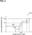
  • 4 ist ein Kennfeld, das eine Beziehung zwischen einem Kühlmitteldruck und einem Speisungs- bzw. Erregungsbetriebsdauerwert zeigt, das in einer Fahrzeugklimaanlage gemäß einem Ausführungsbeispiel verwendet wird. 4 FIG. 11 is a map showing a relationship between a refrigerant pressure and a feed-in duty value used in a vehicle air conditioner according to an embodiment. FIG.
  • 5 ist ein Ablaufdiagramm, das Schritte eines Prozesses zum Einstellen eines oberen Grenzwertes der Drehzahl einer Lüftervorrichtung zeigt, der durch eine Fahrzeugklimaanlage gemäß einem Ausführungsbeispiel ausgeführt wird. 5 FIG. 10 is a flowchart showing steps of a process of setting an upper limit value of the rotational speed of a fan device executed by a vehicle air conditioner according to an embodiment.
  • 6 ist ein Graph, der eine Beziehung zwischen einem Erregungsbetriebsdauerwert und Geräuschpegeln in einer Fahrzeugklimaanlage gemäß einem Ausführungsbeispiel zeigt. 6 FIG. 10 is a graph showing a relationship between an energization duty value and noise levels in a vehicle air conditioner according to an embodiment. FIG.
  • 7 ist ein Ablaufdiagramm, das Schritte eines Prozesses zum Einstellen eines oberen Grenzwertes der Drehzahl einer Lüftervorrichtung zeigt, der durch eine Fahrzeugklimaanlage gemäß einem weiteren Ausführungsbeispiel ausgeführt wird. 7 FIG. 10 is a flowchart showing steps of a process of setting an upper limit value of the rotational speed of a fan device that is executed by a vehicle air conditioner according to another embodiment.
  • 8 ist ein Ablaufdiagramm, das Schritte eines Prozesses zum Einstellen eines oberen Grenzwertes der Drehzahl einer Lüftervorrichtung zeigt, der durch eine Fahrzeugklimaanlage gemäß einem weiteren Ausführungsbeispiel ausgeführt wird. 8th FIG. 10 is a flowchart showing steps of a process of setting an upper limit value of the rotational speed of a fan device that is executed by a vehicle air conditioner according to another embodiment.

DETAILLIERTE BESCHREIBUNGDETAILED DESCRIPTION

Nachstehend wird ein Ausführungsbeispiel einer Fahrzeugklimaanlage beschrieben. Zunächst wird der Überblick der Fahrzeugklimaanlage des gegenwärtigen Ausführungsbeispiels beschrieben.An embodiment of a vehicle air conditioner will be described below. First, the outline of the vehicle air conditioner of the present embodiment will be described.

Wie in 1 gezeigt ist, umfasst eine Fahrzeugklimaanlage 10 des gegenwärtigen Ausführungsbeispiels ein Klimaanlagengehäuse 20 und eine Klimaanlageneinheit 30. Die Fahrzeugklimaanlage 10 ist innerhalb des Instrumentenpanels des Fahrzeugs bereitgestellt.As in 1 includes a vehicle air conditioning system 10 of the present embodiment, an air conditioning case 20 and an air conditioning unit 30 , The Vehicle air conditioning 10 is provided within the instrument panel of the vehicle.

Eine Luftpassage 21 ist innerhalb des Klimaanlagengehäuses 20 ausgebildet. Die Luftpassage 21 ist eine Passage zum Leiten von Klimaanlagenluft in den Fahrgastraum. Die Klimaanlagenluft ist eine Luft zum Anpassen der Temperatur innerhalb des Fahrgastraums. In der Luftpassage 21 strömt die Klimaanlagenluft in die durch den Pfeil W1 in der Zeichnung angegebene Richtung.An air passage 21 is inside the air conditioner housing 20 educated. The air passage 21 is a passage for directing air conditioning air into the passenger compartment. The air conditioning air is an air for adjusting the temperature within the passenger compartment. In the air passage 21 The air conditioning air flows in through the arrow W1 in the drawing indicated direction.

Eine Außenluftansaugöffnung 22 und eine Innenluftansaugöffnung 23 sind an einem Abschnitt stromaufwärts des Klimaanlagengehäuses 20 in der Luftströmungsrichtung W1 ausgebildet. Die Außenluftansaugöffnung 22 und die Innenluftansaugöffnung 23 sind als Abschnitte zum Einbringen von Luft in die Luftpassage 21 ausgebildet. Die Außenluftansaugöffnung 22 ist ein Abschnitt, der Außenluft, die die Luft außerhalb des Fahrgastraums ist, in die Luftpassage 21 einbringt. Die Innenluftansaugöffnung 23 ist ein Abschnitt, der Innenluft, die die Luft innerhalb des Fahrgastraums ist, in die Luftpassage 21 einbringt.An outside air intake opening 22 and an inside air intake opening 23 are at a section upstream of the air conditioner housing 20 in the air flow direction W1 educated. The outside air intake opening 22 and the inside air intake opening 23 are as sections for introducing air into the air passage 21 educated. The outside air intake opening 22 is a section of the outside air, which is the air outside the passenger compartment, into the air passage 21 brings. The inside air intake opening 23 is a section of the indoor air, which is the air inside the passenger compartment, into the air passage 21 brings.

Eine Enteiserausblasöffnung 24, eine Gesichtsausblasöffnung 25, und eine Fußausblasöffnung 26 sind in einem Abschnitt des Klimaanlagengehäuses 20 an der Seite stromabwärts in der Luftströmungsrichtung W1 ausgebildet. A deicer outlet 24 , a facial discharge opening 25 , and a foot outlet 26 are in a section of the air conditioning enclosure 20 at the downstream side in the air flow direction W1 educated.

Die Enteiserausblasöffnung 24 bläst die Klimaanlagenluft, die in das Klimaanlagengehäuse 20 strömt, in Richtung einer inneren Oberfläche einer Windschutzscheibe des Fahrzeugs. Die Gesichtsausblasöffnung 25 bläst die Klimaanlagenluft, die in dem Klimaanlagengehäuse 20 strömt, in Richtung eines Fahrers oder eines Passagiers auf einem Passagiersitz. Die Fußausblasöffnung 26 bläst die Klimaanlagenluft, die in dem Klimaanlagengehäuse 20 strömt, in Richtung des Fußes des Fahrers oder des Passagiers auf dem Passagiersitz.The de-icer blow-out opening 24 blows the air conditioning air into the air conditioning case 20 flows toward an inner surface of a windshield of the vehicle. The facial outlet 25 blows the air conditioning air in the air conditioning case 20 flows, towards a driver or a passenger on a passenger seat. The foot outlet 26 blows the air conditioning air in the air conditioning case 20 flows, towards the foot of the driver or passenger on the passenger seat.

Die Klimaanlageneinheit 30 erzeugt Klimaanlagenluft unter Verwendung der in die Luftpassage 21 aus der Außenluftansaugöffnung 22 oder der Innenluftansaugöffnung 23 eingebrachten Luft. Die Klimaanlageneinheit 30 umfasst eine Lüftervorrichtung 31, einen Verdampfer 44, und einen Heizkern 32.The air conditioning unit 30 generates air conditioning air using the air passage 21 from the outside air intake opening 22 or the Innenluftansaugöffnung 23 introduced air. The air conditioning unit 30 includes a fan device 31 , an evaporator 44 , and a heater core 32 ,

Die Lüftervorrichtung 31 ist an der Seite stromabwärts der Außenluftansaugöffnung 22 und der Innenluftansaugöffnung 23 in der Luftströmungsrichtung W1 angebracht. Die Lüftervorrichtung 31 rotiert, wenn diese erregt wird, um einen Luftstrom in der Luftpassage 21 zu erzeugen. Durch Anpassen des Ausmaßes von Strom, der durch die Lüftervorrichtung 31 fließt, wird das Luftvolumen der Klimaanlagenluft, die in der Luftpassage 21 strömt, angepasst.The fan device 31 is at the downstream side of the outside air intake port 22 and the inside air intake opening 23 in the air flow direction W1 appropriate. The fan device 31 rotates when it is energized to allow airflow in the air passage 21 to create. By adjusting the amount of current passing through the fan device 31 flows, the air volume of air conditioning air, which is in the air passage 21 flows, adjusted.

Der Verdampfer 44 ist an der Seite stromabwärts der Lüftervorrichtung 31 in der Luftströmungsrichtung W1 angebracht. Der Verdampfer 44 ist eine Komponente einer Kühlzyklusvorrichtung.The evaporator 44 is on the side downstream of the fan device 31 in the air flow direction W1 appropriate. The evaporator 44 is a component of a refrigeration cycle device.

Wie in 2 gezeigt ist, umfasst die Kühlzyklusvorrichtung 40 einen Kompressor bzw. Verdichter 41, einen Kondensator 42, ein Expansionsventil 43 und den Verdampfer 44. Der Kompressor 41, der Kondensator 42, das Expansionsventil 43 und der Verdampfer 44 sind in einem Zyklus über eine Kühlmittelpassage 45 verbunden.As in 2 is shown includes the refrigeration cycle device 40 a compressor or compressor 41 , a capacitor 42 , an expansion valve 43 and the evaporator 44 , The compressor 41 , the capacitor 42 , the expansion valve 43 and the evaporator 44 are in one cycle via a coolant passage 45 connected.

Der Kompressor 41 verdichtet und stößt das von dem Verdampfer 44 ausgestoßene Kühlmittel aus. Der Kompressor 41 ist ein sogenannter elektrischer Kompressor, der basierend auf eine Erregung bzw. mit Energiebeaufschlagen angetrieben wird. Der Kondensator 42 tauscht Wärme zwischen dem aus dem Kompressor 41 ausgestoßenen Kühlmittel und Außenluft, die Luft außerhalb des Fahrgastraums ist, aus, um Wärme abzustrahlen und das Kühlmittel zu kühlen. Anschließend stößt der Kondensator 42 das gekühlte Kühlmittel aus. Das Expansionsventil 43 expandiert und dekomprimiert das von dem Kondensator 42 ausgestoßene Kühlmittel, und stößt anschließend das dekomprimierte Kühlmittel aus. Der Verdampfer 44 tauscht Wärme zwischen dem aus dem Expansionsventil 43 ausgestoßenen Kühlmittel und der in der in 1 gezeigten Luftpassage 21 strömenden Klimaanlagenluft aus, um das Kühlmittel durch einen Verdampfungsprozess zu verdampfen. Der Verdampfer 44 weist eine Funktion des Kühlens der Klimaanlagenluft in der Luftpassage 21 unter Verwendung von Verdampfungswärme, wenn das Kühlmittel verdampft wird, sowie eine Funktion des Entfeuchtens der Klimaanlagenluft in der Luftpassage 21 auf.The compressor 41 compacts and pushes off the evaporator 44 ejected coolant from. The compressor 41 is a so-called electric compressor, which is driven based on an energization. The capacitor 42 exchanges heat between the compressor 41 discharged coolant and outside air, which is air outside the passenger compartment, to radiate heat and to cool the coolant. Then the condenser hits 42 the cooled coolant. The expansion valve 43 expands and decompresses that from the condenser 42 ejected coolant, and then ejects the decompressed refrigerant. The evaporator 44 exchanges heat between that from the expansion valve 43 ejected coolant and in the in 1 shown air passage 21 flowing air conditioning air to evaporate the coolant through an evaporation process. The evaporator 44 has a function of cooling the air conditioning air in the air passage 21 by using heat of vaporization when the refrigerant is vaporized, and a function of dehumidifying the air conditioning air in the air passage 21 on.

Der Heizkern 32 ist an der Seite stromabwärts des Verdampfers 44 in der Luftströmungsrichtung W1 angebracht. Der Heizkern 32 heizt die Klimaanlagenluft in der Luftpassage 21 unter Verwendung von Maschinenkühlwasser, das durch eine Maschine als eine Wärmequelle zirkuliert, auf.The heating core 32 is on the side downstream of the evaporator 44 in the air flow direction W1 appropriate. The heating core 32 heats the air conditioning air in the air passage 21 using engine cooling water circulating through a machine as a heat source.

Die Klimaanlageneinheit 30 umfasst weiterhin eine Innen-/Außenluft-Umschaltklappe 33, eine Luftmischklappe 34 und Ausblasöffnungs-Umschaltklappen 35. Die Innen-/Außenluft-Umschaltklappe 33 schaltet die in die Luftpassage 21 einzubringende Luft zwischen Außenluft und Innenluft durch Öffnen und Schließen der Außenluftansaugöffnung 22 und der Innenluftansaugöffnung 23 um. Die Luftmischklappe 34 passt das Verhältnis zwischen dem Luftvolumen, der durch den Heizkern 32 strömenden Luft und dem Luftvolumen der den Heizkern 32 umgehenden Luft an. Die Temperatur der Klimaanlagenluft wird durch Anpassen des Verhältnisses zwischen dem Luftvolumen der durch den Heizkern 32 strömenden Luft und dem Luftvolumen der den Heizkern 32 umgehenden Luft, das von dem Öffnungsgrad der Luftmischklappe 34 abhängt, angepasst. Die Ausblasöffnungsumschaltklappen 35 öffnen und schließen jeden der Enteiserausblasöffnung 34, der Gesichtsausblasöffnung 25 und der Fußausblasöffnung 26. In dem Klimaanalgengehäuse 20 erzeugte Klimaanlagenluft wird aus jenen der Ausblasanschlüssen 24 bis 26, die sich in einem geöffneten Zustand befinden, in den Fahrgastraum ausgeblasen.The air conditioning unit 30 further includes an inside / outside air switching door 33 , an air mix door 34 and exhaust port switching flaps 35 , The inside / outside air switching door 33 Turns them into the air passage 21 air to be introduced between outside air and inside air by opening and closing the outside air intake opening 22 and the inside air intake opening 23 around. The air mix door 34 adjusts the ratio between the volume of air passing through the heater core 32 flowing air and the air volume of the heater core 32 oncoming air. The temperature of the air conditioning air is adjusted by adjusting the ratio between the air volume through the heater core 32 flowing air and the air volume of the heater core 32 the air coming in from the opening degree of the air mix door 34 depends, adjusted. The exhaust port changeover doors 35 open and close each of the deicer outlet 34 , the face blowout opening 25 and the foot discharge opening 26 , In the air conditioning enclosure 20 generated air conditioning air is from those of the exhaust ports 24 to 26 , which are in an open state, blown into the passenger compartment.

Als nächstes wird unter Bezugnahme auf 2 ein Maschinenkühlsystem zum Kühlen der Maschine beschrieben. Wie in 2 gezeigt ist, umfasst ein Maschinenkühlsystem 50 einen Kühler 51 und eine Wasserpumpe 52.Next, referring to 2 a machine cooling system for cooling the machine is described. As in 2 includes an engine cooling system 50 a cooler 51 and a water pump 52 ,

Der Kühler 51 ist stromabwärts des Kondensators 42 in einer Luftströmungsrichtung W2 angebracht. Die Luftströmungsrichtung W2 gibt die Richtung an, in der Außenluft strömt. Der Kühler 51 kühlt Kühlwasser, das innerhalb des Kühlers 51 strömt, durch einen Wärmeaustausch zwischen dem Kühlwasser und der Außenluft, die außerhalb strömt. Der Kühler 51 ist mit einem Wassermantel 61 der Maschine 60 in einem Kreislauf über eine Kühlwasserpassage 53 verbunden. Die Kühlwasserpassage 53 weist eine Funktion des Zuführens des in dem Kühler 51 gekühlten Kühlwassers in dem Wassermantel 61, sowie eine Funktion des Rückführens des durch Absorbieren der Wärme der Maschine 60 in dem Wassermantel 61 aufgeheizten Kühlwassers an den Kühler 51 auf.The cooler 51 is downstream of the capacitor 42 in an air flow direction W2 appropriate. The air flow direction W2 indicates the direction in which outside air flows. The cooler 51 cools cooling water inside the cooler 51 flows through a heat exchange between the cooling water and the outside air flowing outside. The cooler 51 is with a water jacket 61 the machine 60 in a cycle via a cooling water passage 53 connected. The cooling water passage 53 has a function of supplying the in the radiator 51 cooled cooling water in the water jacket 61 , as well as a function of returning the by absorbing the heat of the machine 60 in the water jacket 61 heated cooling water to the radiator 51 on.

Die Wasserpumpe 52 ist in der Kühlwasserpassage 53 bereitgestellt. Die Wasserpumpe 52 zirkuliert das Kühlwasser in der Kühlwasserpassage 53 durch Druckbeaufschlagen des Kühlwassers, das durch die Kühlwasserpassage 53 strömt. Die Wasserpumpe 52 wird unter Verwendung einer Bewegungsenergie von der Maschine 60 angetrieben.The water pump 52 is in the cooling water passage 53 provided. The water pump 52 circulates the cooling water in the cooling water passage 53 by pressurizing the cooling water passing through the cooling water passage 53 flows. The water pump 52 is made using a motor power from the machine 60 driven.

Das Maschinenkühlsystem 50 umfasst ferner eine Lüftervorrichtung 70 zum Blasen von Außenluft zu dem Kondensator 42 und dem Kühler 51. Während das Fahrzeug fährt, wird Außenluft dem Kondensator 42 und dem Kühler 51 aufgrund von Wind relativ zu dem Fahrzeug zugeführt. Wenn die Fahrgeschwindigkeit des Fahrzeugs niedrig ist, oder wenn das Fahrzeug gestoppt ist, nimmt die Menge von externer Luft, die dem Kondensator 42 und dem Kühler 51 aufgrund von Wind relativ zu dem Fahrzeug zugeführt wird, ab. Unter solchen Umständen rotiert die Lüftervorrichtung 70, um einen Außenluftstrom in die durch den Pfeil W2 angegebene Richtung zu erzeugen, wodurch das Luftvolumen von dem Kondensator 42 und dem Kühler 51 zugeführten Außenluft beibehalten wird.The engine cooling system 50 further includes a fan device 70 for blowing outside air to the condenser 42 and the radiator 51 , While the vehicle is driving, outside air becomes the condenser 42 and the radiator 51 due to wind relative to the vehicle. When the driving speed of the vehicle is low, or when the vehicle is stopped, the amount of external air entering the condenser decreases 42 and the radiator 51 due to wind relative to the vehicle is supplied from. In such circumstances, the fan device will rotate 70 to get an outside airflow in through the arrow W2 to generate the specified direction, whereby the volume of air from the condenser 42 and the radiator 51 supplied outside air is maintained.

Als nächstes wird mit Bezugnahme auf 3 eine elektrische Konfiguration der Fahrzeugklimaanlage 10 des gegenwärtigen Ausführungsbeispiels beschrieben. Die Fahrzeugklimaanlage 10 umfasst einen Außenlufttemperatursensor 80, einen Innenlufttemperatursensor 81, einen Solarstrahlungssensor 82, einen Nach-Verdampfer-Temperatursensor 83, einen Kühlmitteldrucksensor 84, eine Klimaanlagenbedieneinheit 85, und eine Klimaanlagen-ECU (elektronische Steuerungseinheit) 86. Im gegenwärtigen Ausführungsbeispiel entspricht die Klimaanlagen-ECU 86 einer Steuerung.Next, referring to 3 an electrical configuration of the vehicle air conditioning 10 of the present embodiment. The vehicle air conditioner 10 includes an outside air temperature sensor 80 , an inside air temperature sensor 81 , a solar radiation sensor 82 , a post-evaporator temperature sensor 83 , a coolant pressure sensor 84 , an air conditioning control unit 85 , and an air conditioning ECU (electronic control unit) 86 , In the present embodiment, the air conditioning ECU corresponds 86 a controller.

Der Außenlufttemperatursensor 80 erfasst eine Außenlufttemperatur Tout, die die Temperatur außerhalb des Fahrgastraums ist, und gibt ein Signal entsprechend der erfassten Außenlufttemperatur Tout aus. Der Innenlufttemperatursensor 81 erfasst eine Innenlufttemperatur Tin, die die Temperatur innerhalb des Fahrgastraums ist, und gibt ein Signal entsprechend der erfassten Innenlufttemperatur Tin aus. Der Solarstrahlungssensor 82 erfasst eine Solarstrahlungsmenge As, und gibt ein Signal entsprechend der erfassten Solarstrahlungsmenge As aus. Der Nach-Verdampfer-Temperatursensor 83 erfasst eine Temperatur Te der Luft, die den Verdampfer 44 in der Luftpassage 21 passiert hat, und gibt ein Signal entsprechend der erfassten Nach-Verdampfer-Temperatur Te aus. Wie in 2 gezeigt ist, erfasst der Kühlmitteldrucksensor 84 einen Druck Pr des Kühlmittels unmittelbar, bevor dieses in den Kondensator 42 strömt, und gibt ein Signal entsprechend des erfassten Kühlmitteldrucks Pr aus. Der Kühlmitteldruck Pr ist ein Parameter, der einen Lastzustand des Kühlmittels in der Kühlzyklusvorrichtung 40 angibt. Die Klimaanlagenbedieneinheit 85 ist ein Abschnitt, der durch einen Fahrzeuginsassen bedient wird, wenn verschiedene Operationen der Fahrzeugklimaanlage 10 durchgeführt werden. Die Klimaanlagenbedieneinheit 85 gibt ein Signal entsprechend der Bedienung des Fahrzeuginsassen aus.The outside air temperature sensor 80 detects an outside air temperature Tout, which is the temperature outside the passenger compartment, and outputs a signal corresponding to the detected outside air temperature Tout. The indoor air temperature sensor 81 detects an inside air temperature Tin, which is the temperature inside the passenger compartment, and outputs a signal corresponding to the detected inside air temperature Tin. The solar radiation sensor 82 detects a solar radiation amount As, and outputs a signal corresponding to the detected solar radiation amount As. The post-evaporator temperature sensor 83 detects a temperature Te of the air, which is the evaporator 44 in the air passage 21 has passed, and outputs a signal corresponding to the detected post-evaporator temperature Te. As in 2 is shown, detects the coolant pressure sensor 84 a pressure Pr of the coolant immediately before this into the condenser 42 flows, and outputs a signal corresponding to the detected refrigerant pressure Pr. The refrigerant pressure Pr is a parameter indicating a load state of the refrigerant in the refrigeration cycle device 40 indicates. The air conditioning control unit 85 is a section operated by a vehicle occupant when various operations of the vehicle air conditioner 10 be performed. The air conditioning control unit 85 outputs a signal according to the operation of the vehicle occupant.

Die Klimaanlagen-ECU 86 steuert die Fahrzeugklimaanlage 10 umfassend. Die Klimaanlagen-ECU 86 besteht hauptsächlich aus einem oder mehreren Mikrocomputern mit einer CPU, einem Speicher, und dergleichen.The air conditioning ECU 86 controls the vehicle air conditioning 10 full. The air conditioning ECU 86 consists mainly of one or more microcomputers with a CPU, memory, and the like.

Ein Ausgangssignal von jedem des Außenlufttemperatursensors 80, des Innenlufttemperatursensor 81, des Solarstrahlungssensors 82, des Nach-Verdampfer-Temperatursensors 83, des Kühlmitteldrucksensors 84 und der Klimaanlagenbedieneinheit 85 wird in die Klimaanlagen-ECU 86 eingegeben. Basierend auf diesen Ausgangssignalen bezieht die Klimaanlagen-ECU 86 die Außenlufttemperatur Tout, die Innenlufttemperatur Tin, das Solarstrahlungsausmaß As, die Nach-Verdampfer-Temperatur Te, den Kühlmitteldruck Pr und Bedienerinformationen von der Klimaanlagenbedieneinheit 85. Anschließend, basierend auf diesen Informationen, steuert die Klimaanlagen-ECU 86 die Lüftervorrichtung 31, die Innen-/Außenluft-Umschaltklappe 33, die Luftmischklappe 34, die Ausblasöffnungsumschaltklappe 35 und den Kompressor 41. Die Klimaanlagen-ECU 86 steuert die Drehzahl des Kompressors 41 durch Steuern einer relativen Einschaltdauer der Menge von zu dem Kompressor 41 zugeführten Elektrizität über die Invertervorrichtung 87.An output signal from each of the outside air temperature sensor 80 , the indoor air temperature sensor 81 , the solar radiation sensor 82 , the post-evaporator temperature sensor 83 , the coolant pressure sensor 84 and the air conditioning control unit 85 gets into the air conditioning ECU 86 entered. Based on these output signals, the air conditioning ECU refers 86 the outside air temperature Tout, the inside air temperature Tin, the Solar radiation level As, post-evaporator temperature Te, coolant pressure Pr and operator information from the air conditioner control unit 85 , Subsequently, based on this information, the air conditioning ECU controls 86 the fan device 31 , the inside / outside air switching door 33 , the air mix door 34 , the exhaust port switching door 35 and the compressor 41 , The air conditioning ECU 86 Controls the speed of the compressor 41 by controlling a duty cycle of the amount of fuel to the compressor 41 supplied electricity via the inverter device 87 ,

Die Klimaanlagen-ECU 86 ist kommunikationsfähig mit einer Maschinen-ECU 92 über ein Fahrzeugnetzwerk 100 verbunden. Die Maschinen-ECU 92 steuert die Maschine 60 und die Lüftervorrichtung 70 umfänglich. Die Maschinen-ECU 92 besteht hauptsächlich aus einem Mikrocomputer mit einer CPU, einem Speicher, und dergleichen. Die Maschinen-ECU 92 empfängt Ausgangssignale von jedem eines Wassertemperatursensors 90 und eines Fahrzeuggeschwindigkeitssensors 91.The air conditioning ECU 86 is capable of communication with an engine ECU 92 via a vehicle network 100 connected. The engine ECU 92 controls the machine 60 and the fan device 70 extensively. The engine ECU 92 mainly consists of a microcomputer with a CPU, a memory, and the like. The engine ECU 92 receives output signals from each of a water temperature sensor 90 and a vehicle speed sensor 91 ,

Wie in 2 gezeigt ist, erfasst der Wassertemperatursensor 90 eine Temperatur Tc des Kühlwassers unmittelbar nachdem dieses aus dem Wassermantel 61 der Maschine 60 ausgestoßen wird, und gibt ein Signal entsprechend der erfassten Kühlwassertemperatur Tc aus. Der Fahrzeuggeschwindigkeitssensor 91 erfasst eine Geschwindigkeit Vc des Fahrzeugs, und gibt ein Signal entsprechend der erfassten Fahrzeuggeschwindigkeit Vc aus.As in 2 is shown, the water temperature sensor detected 90 a temperature Tc of the cooling water immediately after this from the water jacket 61 the machine 60 is discharged, and outputs a signal corresponding to the detected cooling water temperature Tc. The vehicle speed sensor 91 detects a speed Vc of the vehicle, and outputs a signal corresponding to the detected vehicle speed Vc.

Basierend auf den Ausgangssignalen dieser Sensoren 90, 91, bezieht die Maschinen-ECU 92 die Informationen der Kühlwassertemperatur Tc und der Fahrzeuggeschwindigkeit Vc. Die Maschinen-ECU 92 bezieht ebenso verschiedene Parameter, die zum Kühlen der Maschine 60 erforderlich sind, basierend auf Ausgangssignalen von verschiedenen Sensoren, die am Fahrzeug montiert sind. Ferner senden und empfangen die Maschinen-ECU 92 und die Klimaanlagen-ECU 86 verschiedene Informationen über das Fahrzeugnetzwerk 100. Die Maschinen-ECU 92 steuert die Maschine 60 und die Lüftervorrichtung 70, basierend auf diesen Informationen. Die Maschinen-ECU 92 steuert die Drehzahl der Lüftervorrichtung 70 durch Steuerung einer relativen Einschaltdauer des Ausmaßes von Strom, der durch die Lüftervorrichtung 70 über die Invertervorrichtung 93 fließt.Based on the output signals of these sensors 90 . 91 , refers to the engine ECU 92 the information of the cooling water temperature Tc and the vehicle speed Vc. The engine ECU 92 also refers to various parameters used to cool the machine 60 based on outputs from various sensors mounted on the vehicle. Further, the engine ECUs send and receive 92 and the air conditioning ECU 86 various information about the vehicle network 100 , The engine ECU 92 controls the machine 60 and the fan device 70 based on this information. The engine ECU 92 Controls the speed of the fan device 70 by controlling a duty cycle of the amount of current passing through the fan device 70 via the inverter device 93 flows.

Als nächstes wird die Operation der Klimaanlagen-ECU 86 und der Maschinen-ECU 92 detailliert beschrieben. Die Maschinen-ECU 92 bezieht Informationen des Kühlmitteldrucks Pr von der Klimaanlagen-ECU 86 über das Fahrzeugnetzwerk 100. Die Maschinen-ECU 92 berechnet einen Erregungsbetriebsdauerwert Df der Lüftervorrichtung 70, basierend auf dem bezogenen Kühlmitteldruck Pr und der durch den Wassertemperatursensor 90 erfassten Kühlwassertemperatur Tc.Next is the operation of the air conditioning ECU 86 and the engine ECU 92 described in detail. The engine ECU 92 relates coolant pressure Pr information from the air conditioning ECU 86 over the vehicle network 100 , The engine ECU 92 calculates an energization duty value Df of the fan device 70 , based on the related refrigerant pressure Pr and by the water temperature sensor 90 detected cooling water temperature Tc.

Insbesondere ist ein Kennfeld M10, das die Beziehung zwischen dem Kühlmitteldruck Pr und dem Erregungsbetriebsdauerwert Df, wie in 4 gezeigt, vorab in dem Speicher der Maschinen-ECU 92 gespeichert. In 4 gibt „Dmax“ den Maximalwert des Erregungsbetriebsdauerwerts an. Das Kennfeld M10 besteht aus einem Niedriggeschwindigkeitskennfeld M11, das durch eine durchgezogene Linie angegeben ist, und einem normalen Kennfeld M12, das durch eine abwechselnd lang und kurz gestrichelte Linie angegeben ist. Im Wesentlichen gilt in dem Niedriggeschwindigkeitskennfeld M11 und dem normalen Kennfeld M12, dass, wenn der Kühlmitteldruck Pr ansteigt, der Erregungsbetriebsdauerwert Df auf einen größeren Wert eingestellt wird. Weiterhin, in dem Niedriggeschwindigkeitskennfeld M11, wird der Erregungsbetriebsdauerwert Df auf einen Wert eingestellt, der größer ist als in dem normalen Kennfeld M12. Wenn die Fahrzeuggeschwindigkeit Vc größer oder gleich einer vorbestimmten Geschwindigkeit Vth1 ist, berechnet die Maschinen-ECU 92 den Erregungsbetriebsdauerwert Df aus dem Kühlmitteldruck Pr unter Verwendung des normalen Kennfeldes M12. Die vorbestimmte Geschwindigkeit Vth1 kann beispielsweise auf 20 [km/h] eingestellt sein. Weiterhin, wenn die Fahrzeuggeschwindigkeit Vc kleiner ist als die vorbestimmte Geschwindigkeit Vth1, berechnet die Maschinen-ECU 92 den Erregungsbetriebsdauerwert Df aus dem Kühlmitteldruck Pr unter Verwendung des Niedriggeschwindigkeitskennfeldes M11, in dem der Erregungsbetriebsdauerwert Df auf einen größeren Wert eingestellt ist, als im normalen Kennfeld M12. Dies liegt daran, dass, wenn die Fahrzeuggeschwindigkeit Vc kleiner ist als die vorbestimmte Geschwindigkeit Vth1, das Luftvolumen von Außenluft, das den Kondensator 42 und den Kühler 51 aufgrund von Wind relativ zu dem Fahrzeug zugeführt wird, abnimmt, und es daher erforderlich ist, die Drehzahl der Lüftervorrichtung 70 zu erhöhen.In particular, a map is M10 indicative of the relationship between the refrigerant pressure Pr and the energization duty value Df, as in FIG 4 shown in advance in the engine ECU memory 92 saved. In 4 "Dmax" indicates the maximum value of the energization duty value. The map M10 consists of a low speed map M11 indicated by a solid line and a normal map M12 , which is indicated by an alternate long and short dashed line. Essentially, in the low speed map M11 and the normal map M12 in that, as the refrigerant pressure Pr increases, the energization duty value Df is set to a larger value. Furthermore, in the low speed map M11 , the energization duty Df is set to a value larger than that in the normal map M12 , When the vehicle speed Vc is equal to or higher than a predetermined speed Vth1, the engine ECU calculates 92 the energization duty Df from the refrigerant pressure Pr using the normal map M12 , The predetermined speed Vth1 may be set to 20 [km / h], for example. Further, when the vehicle speed Vc is less than the predetermined speed Vth1, the engine ECU calculates 92 the energization duty value Df from the refrigerant pressure Pr using the low-speed map M11 in that the excitation duty value Df is set to a larger value than in the normal map M12 , This is because when the vehicle speed Vc is smaller than the predetermined speed Vth1, the air volume of outside air that is the condenser 42 and the radiator 51 due to wind relative to the vehicle is decreasing, and therefore it is necessary, the rotational speed of the fan device 70 to increase.

Basierend auf dem berechneten Erregungsbetriebsdauerwert Df, steuert die Maschinen-ECU 92 die relative Einschaltdauer des Erregungsausmaßes, das von der Invertervorrichtung 93 der Lüftervorrichtung 70 zugeführt wird. Wenn der Erregungsbetriebsdauerwert Df ansteigt, steigt das Erregungsausmaß der Lüftervorrichtung 70 an, so dass die Drehzahl der Lüftervorrichtung 70 ansteigt. Die Maschinen-ECU 92 steuert die Drehzahl der Ventiltorvorrichtung 70, basierend auf einer solchen Erregungssteuerung.Based on the calculated energization duty value Df, the engine ECU controls 92 the duty ratio of the amount of energization provided by the inverter device 93 the fan device 70 is supplied. As the energization duty Df increases, the amount of energization of the fan device increases 70 so that the speed of the fan device 70 increases. The engine ECU 92 controls the speed of the Ventililtorvorrichtung 70 based on such excitation control.

Weiterhin überwacht die Maschinen-ECU 92 die Kühlwassertemperatur Tc. Wenn die Kühlwassertemperatur Tc größer oder gleich einer vorbestimmten Temperatur wird, ungeachtet des Berechnungsergebnisses, basierend auf dem in 4 gezeigten Kennfeld M10, wird der Erregungsbetriebsdauerwert Df auf den Maximalwert Dmax eingestellt.Furthermore, the engine ECU monitors 92 the cooling water temperature Tc. When the cooling water temperature Tc becomes equal to or higher than a predetermined temperature irrespective of the calculation result based on the in 4 shown map M10 , the energization duty value Df is set to the maximum value Dmax.

Indessen berechnet die Klimaanlagen-ECU 86 eine Soll-Ausblastemperatur TAO, basierend auf einer eingestellten Temperatur Tset, die in die Klimaanlagenbedieneinheit 85 eingegeben wird, der Außenlufttemperatur Tout, der Innenlufttemperatur Tin und dem Solarstrahlungsausmaß As. Anschließend, basierend auf der berechneten Soll-Ausblastemperatur TAO, berechnet die Klimaanlagen-ECU 86 das Luftvolumen der Lüftervorrichtung 31 und den Öffnungsgrad der Luftmischklappe 34, und steuert die Lüftervorrichtung 31 und die Luftmischklappe 34, basierend auf diesen berechneten Werten.Meanwhile, the air conditioning ECU calculates 86 a desired blow-off temperature TAO, based on a set temperature Tset, in the air conditioning control unit 85 is input, the outside air temperature Tout, the inside air temperature Tin and the solar radiation amount As. Subsequently, based on the calculated target blow-out temperature TAO, the air-conditioning ECU calculates 86 the air volume of the fan device 31 and the degree of opening of the air mix door 34 , and controls the fan device 31 and the air mix door 34 based on these calculated values.

Zusätzlich berechnet die Klimaanlagen-ECU 86 eine Soll-Nach-Verdampfer-Temperatur TEO, basierend auf der Soll-Ausblastemperatur TAO. Die Soll-Nach-Verdampfer-Temperatur TEO ist ein Sollwert der Temperatur der Luft, die den Verdampfer 44 passiert hat. Die Klimaanlagen-ECU 86 berechnet eine Solldrehzahl NAC, die ein Sollwert der Drehzahl des Kompressors 41 ist, durch Durchführen einer rückgekoppelten Steuerung, die die durch den Nach-Verdampfer-Temperatursensor 83 erfassten Nach-Verdampfer-Temperatur Te in Richtung der Soll-Nach-Verdampfer-Temperatur TEO anpasst. Die Klimaanlagen-ECU 86 berechnet einen Erregungsbetriebsdauerwert Dc des Kompressors 41, um die Ist-Drehzahl NAC des Kompressors 41 in Richtung einer Soll-Drehzahl NC anzupassen. Die Klimaanlagen-ECU 86 steuert die relative Einschaltdauer des Ausmaßes von Strom, der von der Invertervorrichtung 87 dem Kompressor 41 zugeführt wird, basierend auf dem berechneten Erregungsbetriebsdauerwert Dc. Wenn der Erregungsbetriebsdauerwert Dc ansteigt, steigt das Erregungsausmaß des Kompressors 41 an, so dass die Drehzahl des Kompressors 41 ansteigt. Die Klimaanlagen-ECU 86 steuert die Drehzahl des Kompressors 41, basierend auf einer solchen Erregungssteuerung.In addition, the air conditioning ECU calculates 86 a target post-evaporator temperature TEO, based on the target blow-out temperature TAO. The target after-evaporator temperature TEO is a setpoint of the temperature of the air, which is the evaporator 44 happened. The air conditioning ECU 86 calculates a setpoint speed NAC, which is a setpoint of the speed of the compressor 41 by performing a feedback control similar to that provided by the post-evaporator temperature sensor 83 detected post-evaporator temperature Te in the direction of the target post-evaporator temperature TEO adapts. The air conditioning ECU 86 calculates an excitation duty value Dc of the compressor 41 to the actual speed NAC of the compressor 41 in the direction of a target speed NC adapt. The air conditioning ECU 86 controls the duty cycle of the amount of current supplied by the inverter device 87 the compressor 41 is supplied based on the calculated excitation duty value Dc. As the energization duty Dc increases, the amount of energization of the compressor increases 41 so that the speed of the compressor 41 increases. The air conditioning ECU 86 Controls the speed of the compressor 41 based on such excitation control.

Weiterhin stellt die Klimaanlagen-ECU 86 einen oberen Grenzwert Nmax der Drehzahl des Kompressors 41, basierend auf der Fahrzeuggeschwindigkeit Vc und dem Kühlmitteldruck Pr ein.Furthermore, the air conditioning ECU 86 an upper limit Nmax of the speed of the compressor 41 , based on the vehicle speed Vc and the refrigerant pressure Pr.

Als nächstes wird unter Bezugnahme auf 5 ein Prozess zum Einstellen des oberen Grenzwertes der Drehzahl Nmax durch die Klimaanlagen-ECU 86 detailliert beschrieben. Die Klimaanlagen-ECU 86 führt den in 5 gezeigten Prozess gemäß einer vorbestimmten Periode aus.Next, referring to 5 a process for setting the upper limit value of the rotational speed Nmax by the air conditioning ECU 86 described in detail. The air conditioning ECU 86 leads the in 5 shown process according to a predetermined period.

Wie in 5 gezeigt ist, bestimmt die Klimaanlagen-ECU 86 zunächst in Schritt S10, ob das Fahrzeug bei niedriger Geschwindigkeit fährt oder nicht. Insbesondere, wenn die Fahrzeuggeschwindigkeit Vc kleiner oder gleich einer vorbestimmten Geschwindigkeit Vth2 ist, bestimmt die Klimaanlagen-ECU 86, dass das Fahrzeug bei niedriger Geschwindigkeit fährt. Wenn weiterhin die Fahrzeuggeschwindigkeit Vc die vorbestimmte Geschwindigkeit Vth2 übersteigt, bestimmt die Klimaanlagen-ECU 86, dass das Fahrzeug bei mittlerer Geschwindigkeit oder hoher Geschwindigkeit fährt. Die vorbestimmte Geschwindigkeit Vth2 wird vorab beispielsweise experimentell bestimmt, so dass die Klimaanlagen-ECU 86 dazu fähig ist, zu bestimmen, ob das Fahrzeug bei niedriger Geschwindigkeit fährt oder nicht. Die vorbestimmte Geschwindigkeit Vth2 ist in dem Speicher der Klimaanlagen-ECU 86 gespeichert.As in 5 shown determines the air conditioning ECU 86 first in step S10 whether the vehicle is driving at low speed or not. Specifically, when the vehicle speed Vc is less than or equal to a predetermined speed Vth2, the air conditioning ECU determines 86 in that the vehicle is driving at low speed. Further, when the vehicle speed Vc exceeds the predetermined speed Vth2, the air conditioning ECU determines 86 in that the vehicle is running at medium speed or high speed. The predetermined speed Vth2 is previously determined experimentally, for example, so that the air conditioning ECU 86 is capable of determining whether the vehicle is running at low speed or not. The predetermined speed Vth2 is in the air conditioner ECU memory 86 saved.

Wenn in Schritt S10 eine negative Bestimmung getroffen wird, d. h., wenn das Fahrzeug bei mittlerer Geschwindigkeit oder hoher Geschwindigkeit fährt, stellt die Klimaanlagen-ECU 86 den oberen Grenzwert Nmax der Drehzahl des Kompressors 41 in Schritt S14 auf einen ersten oberen Grenzwert Nmax1 ein. Der erste obere Grenzwert Nmax1 ist auf den Maximalwert der Drehzahl des Kompressors 41 eingestellt, bei der es einer Person im Umfeld des Fahrzeugs oder dergleichen schwierig ist, das Betriebsgeräusch des Kompressors 41 als Lärm wahrzunehmen, während das Fahrzeug bei mittlerer Geschwindigkeit oder hoher Geschwindigkeit fährt. Der erste obere Grenzwert Nmax1 wird vorab beispielsweise experimentell erhalten, und ist in dem Speicher der Klimaanlagen-ECU 86 gespeichert.When in step S10 a negative determination is made, that is, when the vehicle is running at medium speed or high speed, the air conditioning ECU stops 86 the upper limit Nmax of the speed of the compressor 41 in step S14 to a first upper limit Nmax1. The first upper limit Nmax1 is at the maximum value of the speed of the compressor 41 set, in which it is difficult for a person around the vehicle or the like, the operating noise of the compressor 41 to perceive noise as the vehicle is traveling at medium speed or high speed. The first upper limit value Nmax1 is previously obtained experimentally, for example, and is in the memory of the air conditioning ECU 86 saved.

Wenn in Schritt S10 eine zustimmende Bestimmung getroffen wird, d. h., wenn das Fahrzeug bei niedriger Geschwindigkeit fährt, bestimmt die Klimaanlagen-ECU 86 in Schritt S11, ob die Drehzahl der Lüftervorrichtung 70 größer oder gleich einer vorbestimmten Drehzahl ist. Die vorbestimmte Drehzahl ist ein Wert, der eine Bestimmung darüber ermöglicht, ob die Lüftervorrichtung 70 bei einer Drehzahl rotiert oder nicht, bei der der Lärm des Kompressors 41 durch den Lärm der Lüftervorrichtung 70 übertönt werden kann.When in step S10 an affirmative determination is made, that is, when the vehicle is running at low speed, the air conditioning ECU determines 86 in step S11 , if the speed of the fan device 70 is greater than or equal to a predetermined speed. The predetermined speed is a value that allows a determination as to whether the fan device 70 rotated at a speed or not, at which the noise of the compressor 41 through the noise of the fan device 70 can be drowned out.

Insbesondere wird der Erregungsbetriebsdauerwert Df der Lüftervorrichtung 70, basierend auf dem Kühlmitteldruck Pr eingestellt, wie in 4 gezeigt ist. Daher korreliert die Drehzahl der Lüftervorrichtung 70 mit dem Kühlmitteldruck Pr. Durch diese Verwendung schätzt die Klimaanlagen-ECU 86 ab, dass die Drehzahl der Lüftervorrichtung 70 größer oder gleich der vorbestimmten Drehzahl ist, basierend auf dem Kühlmitteldruck Pr, der größer oder gleich dem vorbestimmten Druck Pth1 ist. Ferner schätzt die Klimaanlagen-ECU 86 ab, dass die Drehzahl der Lüftervorrichtung 70 kleiner ist als die vorbestimmte Drehzahl, basierend auf dem Kühlmitteldruck Pr, der kleiner ist als der vorbestimmte Druck Pth1. Der vorbestimmte Druck Pth1 ist vorab experimentell oder dergleichen auf einen Wert eingestellt, der eine Bestimmung darüber ermöglicht, ob die Drehzahl der Lüftervorrichtung 70 größer oder gleich der vorbestimmten Drehzahl ist oder nicht, und ist in dem Speicher der Klimaanlagen-ECU 86 gespeichert.Specifically, the energization duty value Df of the fan device becomes 70 , based on the coolant pressure Pr set as in 4 is shown. Therefore, the speed of the fan device is correlated 70 with the refrigerant pressure Pr. By this use, the air conditioning ECU estimates 86 from that the speed of the fan device 70 is greater than or equal to the predetermined rotational speed based on the coolant pressure Pr which is greater than or equal to the predetermined pressure Pth1. Furthermore, the air conditioning ECU estimates 86 from that the speed of the fan device 70 is less than the predetermined speed, based on the refrigerant pressure Pr, which is smaller than the predetermined pressure Pth1. The predetermined pressure Pth1 is previously set experimentally or the like to a value that enables a determination as to whether the rotational speed of the fan device 70 is greater than or equal to the predetermined speed, and is in the air conditioner ECU memory 86 saved.

Die Klimaanlagen-ECU 86 trifft in Schritt S11 eine negative Bestimmung, wenn der Kühlmitteldruck Pr kleiner ist als der vorbestimmte Druck Pth1. D. h., dass die Klimaanlagen-ECU 86 abschätzt, dass die Drehzahl der Lüftervorrichtung 70 kleiner ist als die vorbestimmte Drehzahl. In diesem Fall, in Schritt S12, stellt die Klimaanlagen-ECU 86 den oberen Grenzwert Nmax der Drehzahl des Kompressors 41 auf einen zweiten oberen Grenzwert Nmax2 ein. Der zweite obere Grenzwert Nmax2 ist auf einen Maximalwert der Drehzahl des Kompressors 41 eingestellt, bei der eine Person im Umfeld des Fahrzeugs oder dergleichen das Betriebsgeräusch des Kompressors 41 nicht als Lärm wahrnimmt, wenn das Fahrzeug gestoppt ist oder bei niedriger Geschwindigkeit fährt. Der zweite obere Grenzwert Nmax2 ist ein Wert kleiner als der erste obere Grenzwert Nmax1. Der zweite obere Grenzwert Nmax2 wird vorab beispielsweise experimentell erhalten, und ist in dem Speicher der Klimaanlagen-ECU 86 gespeichert.The air conditioning ECU 86 meets in step S11 a negative determination when the refrigerant pressure Pr is less than the predetermined pressure Pth1. That is, the air conditioning ECU 86 estimates that the speed of the fan device 70 is less than the predetermined speed. In this case, in step S12 , sets the air conditioning ECU 86 the upper limit Nmax of the speed of the compressor 41 to a second upper limit Nmax2. The second upper limit Nmax2 is at a maximum value of the speed of the compressor 41 set, in which a person around the vehicle or the like, the operating noise of the compressor 41 does not perceive as noise when the vehicle is stopped or at low speed. The second upper limit value Nmax2 is a value smaller than the first upper limit value Nmax1. The second upper limit value Nmax2 is preliminarily obtained, for example, experimentally, and is in the memory of the air conditioning ECU 86 saved.

Die Klimaanlagen-ECU 86 trifft in Schritt S11 eine positive Bestimmung, wenn der Kühlmitteldruck Pr größer oder gleich dem vorbestimmten Druck Pth1 ist. D. h., dass die Klimaanlagen-ECU 86 abschätzt, dass die Drehzahl der Lüftervorrichtung 70 größer oder gleich der vorbestimmten Drehzahl ist. In diesem Fall kann der Lärm des Kompressors 41 durch den Lärm der Lüftervorrichtung 70 übertönt werden. Daher, in Schritt S13, stellt die Klimaanlagen-ECU 86 den oberen Grenzwert der Drehzahl Nmax des Kompressors 41 auf einen dritten oberen Grenzwert Nmax3, der kleiner ist als der erste obere Grenzwert Nmax1 und größer ist als der zweite obere Grenzwert Nmax2, ein. Der dritte obere Grenzwert Nmax3 ist auf den Maximalwert der Drehzahl des Kompressors 41 eingestellt, bei der es einer Person im Umfeld des Fahrzeugs oder dergleichen schwierig ist, das Betriebsgeräusch des Kompressors 41 als Lärm wahrzunehmen, aufgrund dessen, dass dieses durch den Lärm der Lüftervorrichtung 70 übertönt wird. Der dritte obere Grenzwert Nmax3 wird vorab beispielsweise experimentell erhalten, und ist im Speicher der Klimaanlagen-ECU 86 gespeichert.The air conditioning ECU 86 meets in step S11 a positive determination when the refrigerant pressure Pr is equal to or higher than the predetermined pressure Pth1. That is, the air conditioning ECU 86 estimates that the speed of the fan device 70 is greater than or equal to the predetermined speed. In this case, the noise of the compressor 41 through the noise of the fan device 70 be drowned out. Therefore, in step S13 , sets the air conditioning ECU 86 the upper limit of the speed Nmax of the compressor 41 to a third upper limit Nmax3, which is smaller than the first upper limit Nmax1 and greater than the second upper limit Nmax2, a. The third upper limit Nmax3 is at the maximum value of the speed of the compressor 41 set, in which it is difficult for a person around the vehicle or the like, the operating noise of the compressor 41 perceived as noise due to the fact that this is due to the noise of the fan device 70 is drowned out. The third upper limit Nmax3 is preliminarily obtained, for example, experimentally, and is in the memory of the air conditioning ECU 86 saved.

Als nächstes wird ein Betriebsbeispiel der Fahrzeugklimaanlage 10 des gegenwärtigen Ausführungsbeispiels beschrieben. Wenn das Fahrzeug bei niedrige Geschwindigkeit fährt und der Kühlmitteldruck Pr größer oder gleich dem vorbestimmten Druck Pth1 ist, wie in 4 gezeigt ist, wird der Erregungsbetriebsdauerwert Df der Lüftervorrichtung 70 eingestellt, um größer oder gleich einem vorbestimmten Wert Df1 zu sein. Indessen, wie durch die durchgezogene Linie Nf in 6 gezeigt ist, verläuft der externe Lärmpegel der Lüftervorrichtung 70 ungefähr proportional zu dem Erregungsbetriebsdauerwert Df der Lüftervorrichtung 70. Daher, wenn der Erregungsbetriebsdauerwert Df größer oder gleich dem vorbestimmten Wert Df1 ist, wird der externe Lärmpegel der Lüftervorrichtung 70 größer oder gleich einem vorbestimmten Pegel Nf1.Next, an example of operation of the vehicle air conditioner will be described 10 of the present embodiment. When the vehicle is running at low speed and the refrigerant pressure Pr is equal to or higher than the predetermined pressure Pth1, as in FIG 4 is shown, the excitation duty value Df of the fan device 70 set to be greater than or equal to a predetermined value Df1. Meanwhile, as by the solid line Nf in 6 is shown, runs the external noise level of the fan device 70 approximately proportional to the excitation operating time value Df of the fan device 70 , Therefore, when the energization duty value Df is greater than or equal to the predetermined value df1 is, the external noise level of the fan device 70 greater than or equal to a predetermined level Nf1 ,

Wenn indessen der obere Grenzwert der Drehzahl Nmax des Kompressors 41 auf den zweiten oberen Grenzwert Nmax2 eingestellt ist, ist der Lärmpegel des Kompressors 41 kleiner oder gleich einem Soll-Lärmpegel Nc1. Der Soll-Lärmpegel Nc1 ist ein maximaler Lärmpegel, bei dem es einer Person im Umfeld des Fahrzeugs oder dergleichen schwierig ist, das Betriebsgeräusch des Kompressors 41 als Lärm wahrzunehmen, wenn das Fahrzeug gestoppt ist oder bei niedriger Geschwindigkeit fährt.If, however, the upper limit of the speed Nmax of the compressor 41 is set to the second upper limit Nmax2, is the noise level of the compressor 41 less than or equal to a target noise level Nc1 , The nominal noise level Nc1 is a maximum noise level, in which it is difficult for a person around the vehicle or the like, the operating noise of the compressor 41 as a noise when the vehicle is stopped or at low speed.

Weiterhin, wenn der externe Lärmpegel der Lüftervorrichtung 70 größer oder gleich dem vorbestimmten Pegel Nf1 ist, wird der obere Grenzwert Nmax der Drehzahl des Kompressors 41 auf den dritten oberen Grenzwert Nmax3 eingestellt, der größer ist als der zweite obere Grenzwert Nmax2. Aufgrund dessen ist der Maximalwert des Lärmpegels des Kompressors 41 der Lärmpegel Nc2, der größer ist als der Soll-Lärmpegel Nc1. Jedoch, in diesem Fall, weil der Lärmpegel der Lüftervorrichtung 70 größer ist als der maximale Lärmpegel Nc2 des Kompressors 41, wird der Lärm des Kompressors 41 durch den Lärm der Lüftervorrichtung 70 übertönt. Dies trifft wegen den folgenden Gründen zu.Furthermore, if the external noise level of the fan device 70 greater than or equal to the predetermined level Nf1 is, the upper limit Nmax the speed of the compressor 41 set to the third upper limit Nmax3, which is greater than the second upper limit Nmax2. Because of this, the maximum value of the noise level of the compressor is 41 the noise level Nc2 which is greater than the target noise level Nc1 , However, in this case, because the noise level of the fan device 70 is greater than the maximum noise level Nc2 of the compressor 41 , the noise of the compressor 41 through the noise of the fan device 70 drowned. This is true for the following reasons.

Weil das Betriebsgeräusch der Lüftervorrichtung 70, die die Außenluft zu dem Kondensator 42 und dem Kühler 51 bläst, ein vertrautes Geräusch ist, ist es unwahrscheinlich, dass sich eine Person im Umfeld des Fahrzeuges oder dergleichen unbehaglich fühlt. Andererseits, weil das Betriebsgeräusch des Kompressors 41 im Vergleich mit dem Betriebsgeräusch der Lüftervorrichtung 70 ein unangenehmes Geräusch ist, ist es wahrscheinlicher, dass eine Person im Umfeld des Fahrzeuges oder dergleichen einen Lärm wahrnimmt. Aufgrund dessen, wenn der Lärmpegel der Lüftervorrichtung 70 höher ist als der Lärmpegel des Kompressors 41, wird der Lärm des Kompressors 41 durch den Lärm der Lüftervorrichtung 70 übertönt, so dass es schwierig wird, dass das Betriebsgeräusch des Kompressors 41 als Lärm wahrgenommen wird.Because the operating noise of the fan device 70 that the outside air to the condenser 42 and the radiator 51 is a familiar sound, it is unlikely that a person feels uncomfortable around the vehicle or the like. On the other hand, because the operating noise of the compressor 41 in comparison with the operating noise of the fan device 70 is an unpleasant sound, it is more likely that a person perceives a noise in the vicinity of the vehicle or the like. Because of this, when the noise level of the fan device 70 is higher than the noise level of the compressor 41 , the noise of the compressor 41 through the noise of the fan device 70 drowned out, making it difficult to control the operating noise of the compressor 41 is perceived as noise.

Gemäß der Fahrzeugklimaanlage 10 des vorstehend beschriebenen gegenwärtigen Ausführungsbeispiels ist es möglich, die in den folgenden Punkten (1) und (2) beschriebenen Funktionen und Effekte zu erhalten.

  1. (1) Auch, wenn das Fahrzeug bei niedriger Geschwindigkeit fährt, kann die Drehzahl des Kompressors 41 bis zu einem dritten oberen Grenzwert Nmax3 erhöht werden, so dass die Kühlleistungsfähigkeit erhöht werden kann. Zusätzlich, weil der Lärm des Kompressors 41 durch den Lärm der Lüftervorrichtung 70 übertönt wird, ist es schwierig, dass eine Person im Umfeld des Fahrzeugs oder dergleichen den Lärm des Kompressors 41 wahrnimmt. Daher kann bzgl. Menschen im Umfeld des Fahrzeugs oder dergleichen eine Unannehmlichkeit reduziert werden. Ferner ist es unnötig, die Masse des Kompressors 41 zu erhöhen oder die Geräuschisolierungseigenschaften des Fahrzeugs zu verbessern, um den Lärm des Kompressors 41 zu reduzieren. Demzufolge ist es möglich, Kosten zu reduzieren.
  2. (2) Die Klimaanlagen-ECU 86 bestimmt, dass die Drehzahl der Lüftervorrichtung 70 kleiner ist als die vorbestimmte Drehzahl, basierend auf dem Kühlmitteldruck Pr, der kleiner ist als der vorbestimmte Druck Pth1. Weiterhin bestimmt die Klimaanlagen-ECU 86, dass die Drehzahl der Lüftervorrichtung 70 größer oder gleich der vorbestimmten Drehzahl ist, basierend darauf, dass der Kühlmitteldruck Pr größer oder gleich einem vorbestimmten Druck Pth1 ist. Aufgrund dessen ist es möglich, einfach die Drehzahl der Lüftervorrichtung 70 abzuschätzen, ohne, dass ein Sensor erforderlich ist, der direkt die Drehzahl der Lüftervorrichtung 70 misst.
According to the vehicle air conditioner 10 of the above-described present embodiment, it is possible to obtain the following in the following points ( 1 ) and (2) described functions and effects.
  1. (1) Also, when the vehicle is running at low speed, the speed of the compressor may be high 41 can be increased to a third upper limit Nmax3, so that the cooling performance can be increased. In addition, because of the noise of the compressor 41 through the noise of the fan device 70 is drowned out, it is difficult for a person around the vehicle or the like the noise of the compressor 41 perceives. Therefore, an inconvenience can be reduced with respect to people around the vehicle or the like. Furthermore, it is unnecessary, the mass of the compressor 41 To increase or improve the noise insulation properties of the vehicle to the noise of the compressor 41 to reduce. As a result, it is possible to reduce costs.
  2. (2) The air conditioning ECU 86 determines that the speed of the fan device 70 is less than the predetermined speed, based on the refrigerant pressure Pr, which is smaller than the predetermined pressure Pth1. Furthermore, the air conditioning ECU determines 86 in that the speed of the fan device 70 is greater than or equal to the predetermined speed based on that the refrigerant pressure Pr is equal to or higher than a predetermined pressure Pth1. Because of this, it is possible to simply change the speed of the fan device 70 estimate, without, that a sensor is necessary, which directly the speed of the fan device 70 measures.

Es sei angemerkt, dass das vorstehend beschrieben Ausführungsbeispiel wie folgt modifiziert werden kann.

  • - Der Kühlmitteldruck Pr und die Außenlufttemperatur Tout verlaufen proportional zueinander. Daher, wie in 7 gezeigt, in Schritt S11, kann die Klimaanlagen-ECU 86, als eine Alternative, einen Prozess des Bestimmens durchführen, ob die Außenlufttemperatur Tout größer oder gleich einer vorbestimmten Temperatur Tth1 ist oder nicht. D. h., dass die Klimaanlagen-ECU 86 abschätzt, dass die Drehzahl der Lüftervorrichtung 70 kleiner ist als die vorbestimmte Drehzahl, basierend auf der Außenlufttemperatur Tout, die kleiner ist als die vorbestimmte Temperatur Tth1. Ferner schätzt die Klimaanlagen-ECU 86 ab, dass die Drehzahl der Lüftervorrichtung 70 größer oder gleich der vorbestimmten Drehzahl ist, basierend darauf, dass die Außenlufttemperatur Tout größer oder gleich der vorbestimmten Temperatur Tth1 ist. Gemäß einer solchen Konfiguration kann in der Fahrzeugklimaanlage 10, anstatt des Kühlmitteldrucksensors 84, ein Kühlmitteldruckschalter verwendet werden, der ein Signal ausgibt, wenn ein beliebiger Kühlmitteldruck erreicht wird. Als eine Folge kann das Design der Fahrzeugklimaanlage 10 vereinfacht werden, und ebenso können Kosten reduziert werden.
  • - Gleichermaßen verlaufen der Kühlmitteldruck Pr und die Innenlufttemperatur Tin proportional zueinander. Daher, wie in 8 gezeigt ist, in Schritt S11, kann die Klimaanlagen-ECU 86, als eine Alternative, einen Prozess des Bestimmens durchführen, ob die Innenlufttemperatur Tin größer oder gleich einer vorbestimmten Temperatur Tth2 ist oder nicht. D. h., dass die Klimaanlagen-ECU 86 abschätzt, dass die Drehzahl der Lüftervorrichtung 70 kleiner ist als die vorbestimmte Drehzahl, basierend darauf, dass die Innenlufttemperatur Tin kleiner ist als die vorbestimmte Temperatur Tth2. Ferner schätzt die Klimaanlagen-ECU 86 ab, dass die Drehzahl der Lüftervorrichtung 70 größer oder gleich der vorbestimmten Drehzahl ist, basierend darauf, dass die Innenlufttemperatur Tin größer oder gleich der vorbestimmten Temperatur Tth2 ist. Aufgrund dessen kann in der Fahrzeugklimaanlage 10, anstatt des Kühlmitteldrucksensors 84, der Kühlmitteldruckschalter verwendet werden. Als Folge kann das Design der Fahrzeugklimaanlage 10 vereinfacht werden, und ebenso können Kosten reduziert werden.
It should be noted that the above-described embodiment may be modified as follows.
  • - The coolant pressure Pr and the outside air temperature Tout are proportional to each other. Therefore, as in 7 shown in step S11 , the air conditioning ECU 86 as an alternative, perform a process of determining whether the outside air temperature Tout is equal to or higher than a predetermined temperature Tth1 or not. That is, the air conditioning ECU 86 estimates that the speed of the fan device 70 is less than the predetermined speed, based on the outside air temperature Tout, which is smaller than the predetermined temperature Tth1. Furthermore, the air conditioning ECU estimates 86 from that the speed of the fan device 70 is greater than or equal to the predetermined speed based on that the outside air temperature Tout is equal to or higher than the predetermined temperature Tth1. According to such a configuration, in the vehicle air conditioner 10 instead of the coolant pressure sensor 84 , a refrigerant pressure switch may be used which outputs a signal when any refrigerant pressure is reached. As a result, the design of the vehicle air conditioner 10 can be simplified, and costs can also be reduced.
  • - Similarly, the refrigerant pressure Pr and the inner air temperature Tin are proportional to each other. Therefore, as in 8th is shown in step S11 , the air conditioning ECU 86 as an alternative, perform a process of determining whether or not the inside air temperature Tin is greater than or equal to a predetermined temperature Tth2. That is, the air conditioning ECU 86 estimates that the speed of the fan device 70 is less than the predetermined speed, based on that the inside air temperature Tin is smaller than the predetermined temperature Tth2. Furthermore, the air conditioning ECU estimates 86 from that the speed of the fan device 70 is greater than or equal to the predetermined speed based on that the inside air temperature Tin is greater than or equal to the predetermined temperature Tth2. Due to this, in the vehicle air conditioner 10 instead of the coolant pressure sensor 84 , the refrigerant pressure switch are used. As a result, the design of the vehicle air conditioning 10 can be simplified, and costs can also be reduced.

Die durch die Klimaanlagen-ECU 86 und der Maschinen-ECU 92 bereitgestellten Einrichtungen und/oder Funktionen können durch in einem materiellen Speicher gespeicherten Software, einen oder mehrere Computer, die diese Software ausführen, Software alleine, Hardware alleine, oder eine Kombination von Software und Hardware bereitgestellt werden. Wenn beispielsweise die Klimaanlagen-ECU 86 und die Maschinen-ECU 92 durch eine oder mehrere elektronische Schaltungen bereitgestellt sind, die Hardware darstellen, können diese elektronischen Schaltungen durch eine oder mehrere digitale Schaltungen umfassend eine Vielzahl von Logikschaltungen, oder eine oder mehrere Analogschaltungen bereitgestellt werden.

  • - Die vorliegende Offenbarung ist nicht auf die vorstehenden spezifischen Beispiele eingeschränkt. Es ist einem Fachmann ersichtlich, dass die vorstehend beschriebenen spezifischen Beispiele angemessen modifiziert werden können, und diese Modifikationen sind ebenfalls im Umfang der vorliegenden Offenbarung umfasst, solange diese Merkmale der vorliegenden Offenbarung aufweisen. Die Elemente, die Anordnung, die Zustände, die Form, etc., der vorstehend beschriebenen spezifischen Beispiele sind nicht auf die veranschaulichten beschränkt, und können angemessen modifiziert werden. Die Kombinationen von in jedem der vorstehend beschriebenen spezifischen Beispiele enthaltenen Elemente können angemessen modifiziert werden, solange keine technische Inkonsistenz auftritt.
The through the air conditioning ECU 86 and the engine ECU 92 The facilities and / or functions provided may be provided by software stored in a physical memory, one or more computers executing this software, software alone, hardware alone, or a combination of software and hardware. For example, if the air conditioning ECU 86 and the engine ECU 92 provided by one or more electronic circuits representing hardware, these electronic circuits may be provided by one or more digital circuits including a plurality of logic circuits, or one or more analog circuits.
  • The present disclosure is not limited to the above specific examples. It will be apparent to those skilled in the art that the specific examples described above may be modified as appropriate, and such modifications are also within the scope of the present disclosure as long as they have features of the present disclosure. The elements, arrangement, conditions, shape, etc., of the specific examples described above are not limited to those illustrated, and may be appropriately modified. The combinations of in each of the above may be appropriately modified as long as no technical inconsistency occurs.

ZITATE ENTHALTEN IN DER BESCHREIBUNG QUOTES INCLUDE IN THE DESCRIPTION

Diese Liste der vom Anmelder aufgeführten Dokumente wurde automatisiert erzeugt und ist ausschließlich zur besseren Information des Lesers aufgenommen. Die Liste ist nicht Bestandteil der deutschen Patent- bzw. Gebrauchsmusteranmeldung. Das DPMA übernimmt keinerlei Haftung für etwaige Fehler oder Auslassungen.This list of the documents listed by the applicant has been generated automatically and is included solely for the better information of the reader. The list is not part of the German patent or utility model application. The DPMA assumes no liability for any errors or omissions.

Zitierte PatentliteraturCited patent literature

  • JP 2016136720 [0001]JP 2016136720 [0001]
  • JP 4048968 B [0006]JP 4048968 B [0006]

Claims (4)

Fahrzeugklimaanlage, mit: einem Kompressor (41), der ein Kühlmittel verdichtet; einem Kondensator (42), der das von dem Kompressor ausgestoßene Kühlmittel durch Austausch von Wärme zwischen dem Kühlmittel und Luft kühlt; einem Expansionsventil (43), das das von dem Kondensator ausgestoßene Kühlmittel expandiert; einem Verdampfer (44), der Klimaanlagenluft, die in einen Fahrgastraum zu blasen ist, kühlt, durch Austausch von Wärme zwischen dem von dem Expansionsventil ausgestoßenen Kühlmittel und der Klimaanlagenluft; und einer Steuerung (86), die den Kompressor steuert, wobei die Steuerung konfiguriert ist, um einen oberen Grenzwert einer Drehzahl des Kompressors auf einen ersten oberen Grenzwert einzustellen, wenn eine Geschwindigkeit eines Fahrzeugs größer oder gleich einer vorbestimmten Geschwindigkeit ist, die Drehzahl des Kompressors auf einen zweiten oberen Grenzwert einzustellen, der kleiner ist als der erste obere Grenzwert, wenn die Geschwindigkeit des Fahrzeugs kleiner ist als die vorbestimmte Geschwindigkeit und eine Drehzahl einer Lüftervorrichtung (70), die dem Kondensator Luft zuführt, kleiner ist als eine vorbestimmte Drehzahl, und die Drehzahl des Kompressors auf einen dritten oberen Grenzwert einzustellen, der kleiner ist als der erste obere Grenzwert und größer ist als der zweite obere Grenzwert, wenn die Geschwindigkeit des Fahrzeugs kleiner ist als die vorbestimmte Geschwindigkeit und die Drehzahl der Lüftervorrichtung größer oder gleich der vorbestimmten Drehzahl ist. Vehicle air conditioning, with: a compressor (41) that compresses a refrigerant; a condenser (42) which cools the refrigerant discharged from the compressor by exchanging heat between the refrigerant and air; an expansion valve (43) which expands the refrigerant discharged from the condenser; an evaporator (44) that cools air conditioning air to be blown into a passenger compartment by exchanging heat between the refrigerant discharged from the expansion valve and the air conditioning air; and a controller (86) controlling the compressor, the controller configured to set an upper limit of a speed of the compressor to a first upper limit when a speed of a vehicle is greater than or equal to a predetermined speed, set the speed of the compressor to a second upper limit that is less than the first upper limit when the speed of the vehicle is less than the predetermined speed and a speed of a fan device (70) that supplies air to the condenser is less than one predetermined speed, and set the speed of the compressor to a third upper limit that is less than the first upper limit and greater than the second upper limit when the speed of the vehicle is less than the predetermined speed and the speed of the fan device is greater than or equal to the predetermined speed is. Fahrzeugklimaanlage gemäß Anspruch 1, weiterhin mit: einem Kühlmitteldrucksensor (84), der einen Druck des Kühlmittels erfasst, wobei die Steuerung konfiguriert ist, um abzuschätzen, dass die Drehzahl der Lüftervorrichtung kleiner ist als die vorbestimmte Drehzahl, basierend darauf, dass der Druck des Kühlmittels kleiner ist als ein vorbestimmter Druck, und abzuschätzen, dass die Drehzahl der Lüftervorrichtung größer oder gleich der vorbestimmten Drehzahl ist, basierend darauf, dass der Druck des Kühlmittels größer oder gleich dem vorbestimmten Druck ist.Vehicle air conditioning according to Claim 1 , further comprising: a coolant pressure sensor (84) that detects a pressure of the coolant, the controller configured to estimate that the rotational speed of the fan device is less than the predetermined rotational speed based on the pressure of the coolant being less than one predetermined pressure, and to estimate that the rotational speed of the fan device is greater than or equal to the predetermined rotational speed, based on that the pressure of the coolant is greater than or equal to the predetermined pressure. Fahrzeugklimaanlage gemäß Anspruch 1, weiterhin mit: einem Außenlufttemperatursensor (80), der eine Außenlufttemperatur erfasst, die eine Temperatur außerhalb des Fahrgastraums ist, wobei die Steuerung konfiguriert ist, um abzuschätzen, dass die Drehzahl der Lüftervorrichtung kleiner ist als die vorbestimmte Drehzahl, basierend darauf, dass die Außentemperatur kleiner ist als eine vorbestimmte Temperatur, und abzuschätzen, dass die Drehzahl der Lüftervorrichtung größer oder gleich der vorbestimmten Drehzahl ist, basierend darauf, dass die Außentemperatur größer oder gleich der vorbestimmten Temperatur ist.Vehicle air conditioning according to Claim 1 , further comprising: an outside air temperature sensor (80) that detects an outside air temperature that is a temperature outside the passenger compartment, the controller configured to estimate that the speed of the fan device is less than the predetermined speed based on the outside temperature is less than a predetermined temperature, and estimate that the rotational speed of the fan device is greater than or equal to the predetermined rotational speed based on the outer temperature being equal to or higher than the predetermined temperature. Fahrzeugklimaanlage gemäß Anspruch 1, weiterhin mit: einem Innentemperatursensor (81), der eine Innentemperatur erfasst, die eine Temperatur innerhalb des Fahrgastraums ist, wobei die Steuerung konfiguriert ist, um abzuschätzen, dass die Drehzahl der Lüftervorrichtung kleiner ist als die vorbestimmte Drehzahl, basierend darauf, dass die Innentemperatur kleiner ist als eine vorbestimmte Temperatur, und abzuschätzen, dass die Drehzahl der Lüftervorrichtung größer oder gleich der vorbestimmten Drehzahl ist, basierend darauf, dass die Innentemperatur größer oder gleich der vorbestimmten Temperatur ist.Vehicle air conditioning according to Claim 1 , further comprising: an inside temperature sensor (81) that detects an inside temperature that is a temperature inside the passenger compartment, the controller configured to estimate that the speed of the fan device is less than the predetermined speed based on the internal temperature is less than a predetermined temperature, and estimate that the rotational speed of the fan device is greater than or equal to the predetermined rotational speed based on the internal temperature being equal to or higher than the predetermined temperature.
DE112017003489.2T 2016-07-11 2017-06-21 VEHICLE AIR CONDITIONING Pending DE112017003489T5 (en)

Applications Claiming Priority (3)

Application Number Priority Date Filing Date Title
JP2016-136720 2016-07-11
JP2016136720A JP6680119B2 (en) 2016-07-11 2016-07-11 Vehicle air conditioner
PCT/JP2017/022908 WO2018012232A1 (en) 2016-07-11 2017-06-21 Vehicle air-conditioning device

Publications (1)

Publication Number Publication Date
DE112017003489T5 true DE112017003489T5 (en) 2019-04-25

Family

ID=60953062

Family Applications (1)

Application Number Title Priority Date Filing Date
DE112017003489.2T Pending DE112017003489T5 (en) 2016-07-11 2017-06-21 VEHICLE AIR CONDITIONING

Country Status (5)

Country Link
US (1) US10843530B2 (en)
JP (1) JP6680119B2 (en)
CN (1) CN109476209B (en)
DE (1) DE112017003489T5 (en)
WO (1) WO2018012232A1 (en)

Families Citing this family (6)

* Cited by examiner, † Cited by third party
Publication number Priority date Publication date Assignee Title
KR102563739B1 (en) * 2018-06-20 2023-08-17 한온시스템 주식회사 Vehicle electrical equipment cooling system
US11820302B2 (en) * 2018-12-11 2023-11-21 Toyota Motor Engineering & Manufacturing North America, Inc. Vehicle noise reduction for vehicle occupants
CN111660753A (en) * 2019-03-05 2020-09-15 上汽通用汽车有限公司 Automatic control system for pressure in automobile air conditioner pipe
CN110525171A (en) * 2019-08-30 2019-12-03 奇瑞商用车(安徽)有限公司 New-energy automotive air-conditioning refrigeration system VCU control method
CN110843456A (en) * 2019-10-16 2020-02-28 珠海格力电器股份有限公司 Control method and system of automobile air conditioner and computer readable storage medium
US11571947B2 (en) * 2019-11-14 2023-02-07 Ford Global Technologies, Llc Vehicle air control system

Citations (2)

* Cited by examiner, † Cited by third party
Publication number Priority date Publication date Assignee Title
JP4048968B2 (en) 2003-02-12 2008-02-20 株式会社デンソー Air conditioner for vehicles
JP2016136720A (en) 2015-01-20 2016-07-28 株式会社リコー Image processing apparatus, system, image processing method, calibration method, and program

Family Cites Families (10)

* Cited by examiner, † Cited by third party
Publication number Priority date Publication date Assignee Title
JP2003291638A (en) * 2002-04-05 2003-10-15 Nissan Motor Co Ltd Motor fan control device for vehicle
JP2003341335A (en) * 2002-05-27 2003-12-03 Nissan Motor Co Ltd Air-conditioning device for vehicle
JP4165330B2 (en) * 2003-04-16 2008-10-15 株式会社デンソー Air conditioner
JP4534496B2 (en) * 2004-01-22 2010-09-01 日産自動車株式会社 Control device for vehicle cooling fan
JP2006021711A (en) * 2004-07-09 2006-01-26 Honda Motor Co Ltd Air conditioner for vehicle
US7832221B2 (en) * 2006-10-20 2010-11-16 Ford Global Technologies, Llc Vehicle compressor control system and method
JP2011126409A (en) 2009-12-17 2011-06-30 Denso Corp Refrigerating cycle device for vehicle
JP2011245894A (en) 2010-05-24 2011-12-08 Suzuki Motor Corp Vehicle air-conditioning device
JP2011246083A (en) * 2010-05-31 2011-12-08 Suzuki Motor Corp Vehicle air-conditioning device
JP6711258B2 (en) * 2016-12-16 2020-06-17 株式会社デンソー Refrigeration cycle equipment

Patent Citations (2)

* Cited by examiner, † Cited by third party
Publication number Priority date Publication date Assignee Title
JP4048968B2 (en) 2003-02-12 2008-02-20 株式会社デンソー Air conditioner for vehicles
JP2016136720A (en) 2015-01-20 2016-07-28 株式会社リコー Image processing apparatus, system, image processing method, calibration method, and program

Also Published As

Publication number Publication date
US20190152298A1 (en) 2019-05-23
WO2018012232A1 (en) 2018-01-18
CN109476209A (en) 2019-03-15
CN109476209B (en) 2022-01-11
US10843530B2 (en) 2020-11-24
JP2018008541A (en) 2018-01-18
JP6680119B2 (en) 2020-04-15

Similar Documents

Publication Publication Date Title
DE112017003489T5 (en) VEHICLE AIR CONDITIONING
DE102014109524B4 (en) Method of controlling an automotive air conditioning system
DE102017108809A1 (en) TRACTION BATTERY COOLING SYSTEM WITH COOLANT PROPORTIONAL VALVE
DE102009031504B4 (en) Method of controlling an HVAC system
DE102009020836B4 (en) Method of operating and method of controlling a heating, ventilation and air conditioning system for improved vehicle fuel economy
DE102017108778A1 (en) Traction battery cooling system for an electrified vehicle
DE112011101851B4 (en) Air conditioning for one vehicle
DE102012102438B4 (en) Air conditioning control method using an air conditioning control device
DE60307932T2 (en) Device and method for controlling an electric motor driven blower of a motor vehicle
DE112011101770B4 (en) Air conditioning for one vehicle
DE112010002544B4 (en) Control method for a vehicle
DE102015113574A1 (en) WINDSHIELD FENDER REMOVAL SYSTEM AND METHOD
DE102004008912A1 (en) Battery cooling device with sufficient cooling capacity
DE112015005671T5 (en) Air conditioning for vehicle
EP2958763B1 (en) Method and system for preconditioning a heating and/or cooling unit in a motor vehicle
DE102010024854B4 (en) Air conditioning for a vehicle
DE112016004019T5 (en) Vehicle air conditioning device
DE102010000713A1 (en) Cooling air flow controlling method for condenser of air conditioning apparatus used for air conditioning cabin of passenger car, involves actuating radiator venetian blind in accordance with determined optimized setting of blind
DE102014118037A1 (en) Control method for an integrated cooling system
DE112017005310T5 (en) Vehicle air conditioning
DE102015111932B4 (en) Active damper and electric thermostat integration control method and control device for vehicle
US11021036B2 (en) Battery electric vehicle and method to cool a high voltage powertrain component of a battery electric vehicle
DE102010046027A1 (en) Air conditioning system for e.g. hybrid vehicle, has heater core arranged in housing, and controller reducing air blowing quantity of blower when system is stopped in comparison to air blowing quantity when system is operated
DE102013203907A1 (en) High Voltage Device Cooling System for Electric Vehicle and High Voltage Device Cooling Method for Electric Vehicle
DE102009056616B4 (en) Method for distributing heat in a coolant circuit of a vehicle

Legal Events

Date Code Title Description
R012 Request for examination validly filed
R016 Response to examination communication