DE112011102991B4 - Method and device for 3D measurement by detecting a predetermined pattern - Google Patents
Method and device for 3D measurement by detecting a predetermined pattern Download PDFInfo
- Publication number
- DE112011102991B4 DE112011102991B4 DE112011102991.8T DE112011102991T DE112011102991B4 DE 112011102991 B4 DE112011102991 B4 DE 112011102991B4 DE 112011102991 T DE112011102991 T DE 112011102991T DE 112011102991 B4 DE112011102991 B4 DE 112011102991B4
- Authority
- DE
- Germany
- Prior art keywords
- code
- sequence
- projection
- pattern
- codes
- Prior art date
- Legal status (The legal status is an assumption and is not a legal conclusion. Google has not performed a legal analysis and makes no representation as to the accuracy of the status listed.)
- Expired - Fee Related
Links
- 238000005259 measurement Methods 0.000 title claims abstract description 16
- 238000000034 method Methods 0.000 title claims description 25
- 238000005070 sampling Methods 0.000 claims abstract description 28
- 230000010365 information processing Effects 0.000 claims abstract description 10
- 238000013507 mapping Methods 0.000 claims abstract description 8
- 238000006243 chemical reaction Methods 0.000 claims abstract 2
- 238000001514 detection method Methods 0.000 claims description 29
- 238000003384 imaging method Methods 0.000 claims description 17
- 238000004590 computer program Methods 0.000 claims 1
- 238000012545 processing Methods 0.000 description 64
- 238000012937 correction Methods 0.000 description 44
- 238000004364 calculation method Methods 0.000 description 20
- 238000010586 diagram Methods 0.000 description 10
- 239000003086 colorant Substances 0.000 description 5
- 230000008569 process Effects 0.000 description 4
- 238000012795 verification Methods 0.000 description 4
- 238000007796 conventional method Methods 0.000 description 3
- 238000000605 extraction Methods 0.000 description 3
- 230000006870 function Effects 0.000 description 3
- 238000012986 modification Methods 0.000 description 3
- 230000004048 modification Effects 0.000 description 3
- 230000007423 decrease Effects 0.000 description 2
- 230000001419 dependent effect Effects 0.000 description 2
- 239000000463 material Substances 0.000 description 2
- 230000001133 acceleration Effects 0.000 description 1
- 230000008859 change Effects 0.000 description 1
- 239000000284 extract Substances 0.000 description 1
- 238000000691 measurement method Methods 0.000 description 1
- 238000003909 pattern recognition Methods 0.000 description 1
- 230000009467 reduction Effects 0.000 description 1
Images


Classifications
-
- G—PHYSICS
- G06—COMPUTING; CALCULATING OR COUNTING
- G06T—IMAGE DATA PROCESSING OR GENERATION, IN GENERAL
- G06T7/00—Image analysis
- G06T7/50—Depth or shape recovery
- G06T7/521—Depth or shape recovery from laser ranging, e.g. using interferometry; from the projection of structured light
-
- G—PHYSICS
- G06—COMPUTING; CALCULATING OR COUNTING
- G06V—IMAGE OR VIDEO RECOGNITION OR UNDERSTANDING
- G06V20/00—Scenes; Scene-specific elements
- G06V20/60—Type of objects
- G06V20/64—Three-dimensional objects
-
- G—PHYSICS
- G06—COMPUTING; CALCULATING OR COUNTING
- G06F—ELECTRIC DIGITAL DATA PROCESSING
- G06F11/00—Error detection; Error correction; Monitoring
- G06F11/07—Responding to the occurrence of a fault, e.g. fault tolerance
- G06F11/08—Error detection or correction by redundancy in data representation, e.g. by using checking codes
- G06F11/10—Adding special bits or symbols to the coded information, e.g. parity check, casting out 9's or 11's
Abstract
Bildinformationsverarbeitungsvorrichtung, die angepasst ist, eine dreidimensionale Vermessung eines Objekts unter Verwendung eines aufgenommenen Bilds durchzuführen, das durch Projektion eines Projektionsmusters auf das Objekt erhalten wird, wobei das Projektionsmuster erhalten wird durch Zuordnung eines Symbols, das sich von einem zu einem anderen Typ von Code einer Projektionscodefolge unterscheidet, zu jedem Code in einer Projektionscodefolge, in der eine Vielzahl von Typen von Codes zweidimensional angeordnet sind, wobei die Vorrichtung aufweist: eine Erlangungseinrichtung (105) zum Erlangen eines Abbildungsmusters durch Extrahieren von Symbolen aus dem aufgenommenen Bild; eine Umwandlungseinrichtung (106) zum Umwandeln von jedem Symbol in dem durch die Erlangungseinrichtung erlangten Abbildungsmuster in einen entsprechenden Code, um eine Abbildungscodefolge zu erlangen; eine Erzeugungseinrichtung (107) zum Erzeugen einer Informationscodefolge durch Erlangen einer vorbestimmten Anzahl von Codes aus der Abbildungscodefolge gemäß einem Abtastmuster, in dem Abtastpositionen der vorbestimmten Anzahl von Codes und eine Abfolge der Codes definiert sind, und Anordnen der erlangten Codes; und eine Messeinrichtung (109, 110) zum Durchführen einer dreidimensionalen Vermessung des Objekts durch Bestimmen einer Entsprechung zwischen der Informationscodefolge und der Projektionscodefolge basierend auf der Informationscodefolge und dem Abtastmuster, dadurch gekennzeichnet, dass die Erzeugungseinrichtung (107) angepasst ist, als das Abtastmuster zum Erzeugen der Informationscodefolge, ein Abtastmuster, das ermöglicht, die vorbestimmte Anzahl von Codes aus der Abbildungscodefolge unter Verwendung des Abtastmusters zu erlangen, aus einer Vielzahl von Typen von Abtastmustern auszuwählen, und die Messeinrichtung (109, 110) angepasst ist, als die Projektionscodefolge zum Bestimmen der Entsprechung, eine Projektionscodefolge zu ermitteln, die dem ausgewählten Abtastmuster entspricht, das zum Erzeugen der Informationscodefolge verwendet wird, und die mit der erzeugten Informationscodefolge übereinstimmt.An image information processing apparatus adapted to perform a three-dimensional measurement of an object using a captured image obtained by projecting a projection pattern on the object, the projection pattern being obtained by associating a symbol extending from one to another type of code Projection code sequence distinguishes, to each code in a projection code sequence, in which a plurality of types of codes are arranged two-dimensionally, the apparatus comprising: acquiring means (105) for obtaining an image pattern by extracting symbols from the picked-up image; conversion means (106) for converting each symbol in the image pattern acquired by the obtaining means into a corresponding code to obtain a mapping code string; generating means (107) for generating an information code string by obtaining a predetermined number of codes from the image code string according to a sampling pattern in which sampling positions of the predetermined number of codes and a sequence of the codes are defined, and arranging the obtained codes; and measuring means (109, 110) for performing a three-dimensional measurement of the object by determining a correspondence between the information code string and the projection code string based on the information code string and the scanning pattern, characterized in that the generating means (107) is adapted as the scanning pattern for generating the information code string, a scanning pattern enabling to obtain the predetermined number of codes from the image code string using the scanning pattern, selecting from among a plurality of types of scanning patterns, and the measuring means (109, 110) adapted as the projection code string for determining Corresponding to determine a projection code sequence corresponding to the selected scan pattern used to generate the information code sequence and coincident with the generated information code sequence.
Description
TECHNISCHES GEBIETTECHNICAL AREA
Die vorliegende Erfindung bezieht sich auf eine Bildinformationsverarbeitungsvorrichtung, die eine dreidimensionale Vermessung durch Erfassung eines vorbestimmten Musters aus einem Bild durchführt, das durch Projektion des vorbestimmten Musters aufgenommen wird, sowie ein Verfahren zum Steuern der Bildinformationsverarbeitungsvorrichtung.The present invention relates to an image information processing apparatus that performs a three-dimensional measurement by detecting a predetermined pattern from an image taken by projection of the predetermined pattern, and a method of controlling the image information processing apparatus.
HINTERGRUNDTECHNIKBACKGROUND ART
Vorrichtungen, die die dreidimensionale Form von Objekten ver-/messen, sind in verschiedenen Gebieten weit verbreitet, zum Beispiel zum Untersuchen von Teilen in Fabriken im industriellen Bereich oder zum Ver-/Messen der Form von lebenden Organismen im medizinischen Bereich. Insbesondere berührungslose Messverfahren sind in Fällen effektiv, in denen die Gefahr besteht, dass ein Zielobjekt durch Berührung mit einer Messvorrichtung deformiert oder beschädigt werden kann. Bei einer solchen berührungslosen dreidimensionalen Formvermessung ist eine Methode weit verbreitet, bei der ein Triangulationsverfahren unter Verwendung eines Bilds durchgeführt wird, das durch eine Bildaufnahmevorrichtung erhalten wird. Zum Beispiel beschreibt P. M. Griffin, L. S. Narashimhan und S. R. Yee: ”GENERATION OF UNIQUELY ENCODED LIGHT PATTERNS FOR RANGE DATA ACQUISITION”, Pattern Recognition, Vol. 25, Seiten 609 bis 616 (hierin nachstehend Literatur 1) ein Beispiel, bei dem eine dreidimensionale Formvermessung durchgeführt wird, indem ein Punktabfolgemuster, das durch seine Farbe gekennzeichnet ist, mit einem Projektor auf ein Objekt projiziert wird und das reflektierte Licht mit einer Kamera abgebildet wird.Devices that measure / measure the three-dimensional shape of objects are widely used in various fields, for example, to inspect parts in factories in the industrial field or to measure / measure the shape of living organisms in the medical field. In particular, non-contact measuring methods are effective in cases where there is a danger that a target object may be deformed or damaged by contact with a measuring device. In such non-contact three-dimensional shape measurement, there is a widely used method in which a triangulation method is performed by using an image obtained by an image pickup device. For example, PM Griffin, LS Narashimhan and SR Yee: "GENERATION OF UNIQUELY ENCODED LIGHT PATTERNS FOR RANGE DATA ACQUISITION", Pattern Recognition, Vol. 25, pages 609 to 616 (hereinafter Literature 1) describes an example in which a three-dimensional shape measurement is performed by projecting a dot-pattern, which is characterized by its color, with a projector on an object and the reflected light is imaged with a camera.
Nachstehend wird der Vorgang einer dreidimensionalen Vermessung, der in Literatur 1 dargelegt ist, im Speziellen beschrieben. Zunächst wird eine dreifarbige RGB-Punktabfolge, in der die Farbabfolge durch eine zweidimensionale Codefolge bzw. einen zweidimensionalen Codestring in Übereinstimmung mit einer mathematischen Vorschrift bestimmt ist, als ein Projektionsmusterbild mit einem Projektor auf ein Objekt projiziert. Ein Bild des Objekts, auf das das Projektionsmusterbild projiziert wird, wird mit einer Kamera aufgenommen, und eine in dem aufgenommenen Bild beobachtete Punktabfolge wird als eine Abbildungspunktabfolge herausgegriffen. Die Abfolge von benachbarten Farben in der herausgegriffenen Abbildungs-punktabfolge wird als eine Abbildungscodefolge bzw. ein Abbildungscodestring basierend auf einer vorbestimmten Codefolge bzw. einem vorbestimmten Codestring decodiert. Unter Verwendung der mathematischen Vorschrift der Codefolge bzw. des Codestrings des Projektionsmusterbilds wird die Entsprechung bzw. Korrespondenz zwischen Teilcodefolgen bzw. -codestrings von Abschnitten, die in der erlangtem Abbildungscodefolge bzw. dem erlangten Abbildungscodestring enthalten sind, und zweidimensionalen Positionen auf/in der Codefolge bzw. dem Codestring des Projektionsmusterbilds bestimmt. Es werden alle möglichen Teilcodefolgen bzw. -codestrings in der Abbildungscodefolge bzw. dem Abbildungscodestring herausgegriffen, es wird die Entsprechung bzw. Korrespondenz zwischen den Teilcodefolgen bzw. -codestrings und zweidimensionalen Positionen wie vorstehend beschrieben bestimmt, und es werden dreidimensionale Positionen von einzelnen Punkten basierend auf dem Prinzip der Triangulation erhalten. Unter Verwendung des vorstehend beschrieben Vorgangs wird eine dreidimensionale Formvermessung eines Objekts durchgeführt.Hereinafter, the operation of a three-dimensional survey set forth in
Bei dem vorstehend beschriebenen herkömmlichen Beispiel besteht jedoch das Problem, dass es abhängig von der Form des Objekts nicht möglich sein kann, die Entsprechung bzw. Korrespondenz mit Bezug auf ein Gebiet eines aufgenommenen Bilds zu bestimmen, in dem eine Teilcodefolge bzw. ein Teilcodestring einer ausreichenden Größe aus der Abbildungscodefolge bzw. dem Abbildungscodestring nicht herausgegriffen werden kann, so dass eine dreidimensionale Formvermessung nicht durchgeführt werden kann. Außerdem besteht das Problem, dass in einem Fall, in dem eine Abfolge von Punkten, die ursprünglich nicht benachbart zueinander sind, fälschlicherweise aus der Abbildungspunktabfolge herausgegriffen wird, oder in dem Fall, in dem eine Farbe in der Abbildungspunktabfolge infolge von Rauschen oder aus anderen Gründen als eine falsche Farbe erkannt wird, die Codefolge bzw. der Codestring mit einer falschen zweidimensionalen Position in Zusammenhang gebracht wird und ungenaue Ergebnisse einer dreidimensionalen Vermessung ausgegeben werden. Es ist allerdings möglich, eine solche fehlerhafte Entsprechung bzw. Korrespondenz zu erfassen, indem die Länge einer Teilcodefolge bzw. eines Teilcodestrings erhöht wird, die bzw. der bei der Entsprechungs- bzw. Korrespondenzbestimmung verwendet wird, aber anderseits ergibt sich das Problem, dass sich das Gebiet, in dem eine Teilcodefolge bzw. ein Teilcodestring aus der Abbildungscodefolge bzw. dem Abbildungscodestring nicht herausgegriffen werden kann, abhängig von der Form des Objekts sogar noch vergrößern kann.In the conventional example described above, however, there is the problem that depending on the shape of the object, it may not be possible to determine the correspondence with respect to an area of a captured image in which a partial code string of a sufficient one Size can not be selected from the image code sequence or the image code string, so that a three-dimensional shape measurement can not be performed. In addition, there is a problem that, in a case where a succession of points not initially adjacent to each other are erroneously picked out from the imaging point sequence, or in the case where a color in the imaging point sequence is due to noise or other reasons is recognized as an incorrect color, the code string or code string is associated with a wrong two-dimensional position, and inaccurate results of a three-dimensional survey are output. However, it is possible to detect such erroneous correspondence by increasing the length of a subcode string used in the correspondence determination, but on the other hand, the problem arises that the area in which a partial code string or a partial code string can not be extracted from the image code string or the image code string may even increase depending on the shape of the object.
Weitere Hintergrundtechnik ist etwa bekannt aus dem Artikel „REAL-TIME STRUCTURED LIGHT PATTERNS CODING WITH SUBPERFECT SUB-MAPS” von X. Maurice et al., Real-Time Image and Video Processing 2010, Proc. of SPIE, Vol. 7724, 2010, S. 77240E-1, in dem die Verwendung von codiertem strukturierten Licht zur 3D-Rekonstruction thematisiert ist, sowie der Druckschrift
KURZFASSUNG DER ERFINDUNGSUMMARY OF THE INVENTION
Die vorliegende Erfindung wurde in Anbetracht der vorstehend beschriebenen Probleme gemacht, und es wird gemäß einem Ausführungsbeispiel der Erfindung ein robusteres dreidimensionales Ver-/Messungsverfahren bereitgestellt, das eine fehlerhafte Bestimmung einer Entsprechung bzw. Korrespondenz reduziert und dennoch sogar eine dreidimensionale Ver-/Messung von verschiedenartigeren Formen von Objekten ermöglicht.The present invention has been made in view of the above-described problems, and according to an embodiment of the invention, there is provided a more robust three-dimensional metering method which reduces erroneous determination of correspondence, and yet even three-dimensional metering of different ones Allows forms of objects.
Gemäß einem Aspekt der vorliegenden Erfindung ist eine Bildinformationsverarbeitungsvorrichtung bereitgestellt, wie sie in Patentanspruch 1 dargelegt ist.According to one aspect of the present invention, there is provided an image information processing apparatus as set forth in
Auch ist gemäß einem weiteren Aspekt der vorliegenden Erfindung ein Verfahren zum Steuern einer Bildinformationsverarbeitungsvorrichtung bereitgestellt, wie es in Patentanspruch 11 dargelegt ist.Also, according to another aspect of the present invention, there is provided a method of controlling an image information processing apparatus as set out in claim 11.
Ferner ist gemäß einem weiteren Aspekt der vorliegenden Erfindung ein computerlesbares Speichermedium bereitgestellt, wie es in Patentanspruch 13 dargelegt ist.Further, according to another aspect of the present invention, there is provided a computer readable storage medium as set forth in
Etwaige Modifikationen und/oder Ausgestaltungen der vorgenannten Aspekte der vorliegenden Erfindung sind in den jeweiligen abhängigen Patentansprüchen dargelegt.Any modifications and / or embodiments of the aforementioned aspects of the present invention are set forth in the respective dependent claims.
Etwaige Modifikationen und/oder Ausgestaltungen der vorgenannten Aspekte der vorliegenden Erfindung sind in den jeweiligen abhängigen Patentansprüchen dargelegt.Any modifications and / or embodiments of the aforementioned aspects of the present invention are set forth in the respective dependent claims.
Weitere Merkmale der vorliegenden Erfindung werden aus der folgenden Beschreibung von beispielhaften Ausführungsbeispielen unter Bezugnahme auf die beigefügten Zeichnungen deutlich.Other features of the present invention will become apparent from the following description of exemplary embodiments with reference to the accompanying drawings.
KURZE BESCHREIBUNG VON ZEICHNUNGENBRIEF DESCRIPTION OF DRAWINGS
BESCHREIBUNG VON AUSFÜHRUNGSBEISPIELENDESCRIPTION OF EMBODIMENTS
Nachstehend wird hierin ein Beispiel eines bevorzugten Ausführungsbeispiels der vorliegenden Erfindung unter Bezugnahme auf die beigefügten Zeichnungen beschrieben.Hereinafter, an example of a preferred embodiment of the present invention will be described with reference to the accompanying drawings.
Eine Informationserlangungseinheit
Schritt S401: Die Mustererzeugungseinheit
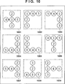
Die in
Die de Bruijn-Sequenz mit k = 3 und m = 3 (mit der Sequenzlänge 33 = 27), die in der u-Richtung bei dem vorliegenden Ausführungsbeispiel verwendet wird, ist eine nachstehend gezeigte Zahlenfolge:
Gleichermaßen ist die de Bruijn-Sequenz mit k = 3 und n = 2 (mit der Sequenzlänge 32 = 9), die in der v-Richtung bei dem vorliegenden Ausführungsbeispiel verwendet wird, nachstehend gezeigt:
Es sollte beachtet werden, dass die de Bruijn-Sequenzen (1) und (2), die bei dem vorliegenden Ausführungsbeispiel verwendet werden, keine Zyklizität zulassen und daher Längen aufweisen, die um m + k – 1 bzw. n + k – 1 länger sind als die ursprünglichen Sequenzlängen. (Der Fall, in dem eine Wiederholung in dem Muster vorliegt, wird nachstehend beschrieben.)It should be noted that the de Bruijn sequences (1) and (2) used in the present embodiment do not allow cyclicity and therefore have lengths longer by m + k-1 and n + k-1, respectively are as the original sequence lengths. (The case where there is a repetition in the pattern will be described below.)
Als Nächstes wird ein Verfahren zum Erzeugen einer Projektionscodefolge unter Verwendung der vorstehend beschriebenen beiden de Bruijn-Sequenzen beschrieben. Zunächst wird in der ersten Zeile in der u-Richtung die de Bruijn-Sequenz in der u-Richtung als die Projektionscodefolge verwendet, wie sie ist. In und nach der zweiten Zeile in der u-Richtung wird ein Ergebnis einer Addition der Werte der de Bruijn-Sequenz in der v-Richtung mit den Werten der Codefolge in einer Zeile direkt vor der interessierenden Zeile als die Codefolge verwendet. Hier wird das Ergebnis einer Addition k-stufig ausgedrückt, wodurch das Ergebnis durch 1 bis k dargestellt wird, und werden Überträge ignoriert. Zum Beispiel wird der erste Zahlenwert ”3” in der durch (2) gezeigten Sequenz zu jedem Wert in der Codefolge in der ersten Zeile (der Codefolge in der untersten Zeile) in
Die durch Verwendung des vorstehend beschriebenen Verfahrens erzeugte Projektionscodefolge hat die Eigenschaft, dass in einer Teilcodefolge, die durch ein Rechteck umgeben bzw. eingefasst ist, das sich an einer beliebigen Position innerhalb der Projektionscodefolge befindet und eine Größe von m × (n + 1) aufweist, eine Informationscodefolge einer Länge von m + n, die durch Abtastung einer vorbestimmten Zeile und einer vorbestimmten Spalte in einer festgelegten Reihenabfolge erhalten wird, exakt einmal in der Projektionscodefolge vorkommt. Diese Eigenschaft wird zur Bestimmung eines Abtastmerkmals in Schritt S408 und zur Codefehlererfassung/-korrektur in Schritt S410 verwendet, die nachstehend beschrieben werden.The projection code sequence generated by using the above-described method has the property that in a partial code string surrounded by a rectangle located at an arbitrary position within the projection code string and having a size of m × (n + 1) , an information code sequence of length m + n obtained by scanning a predetermined line and a predetermined column in a predetermined series order occurs exactly once in the projection code sequence. This property is used to determine a sampling feature in step S408 and code error detection / correction in step S410, which will be described below.
Eine Verarbeitung der folgenden Schritte wird möglich gemacht, indem ein Projektionsmusterbild erzeugt wird, in dem die Projektionscodefolge mit der vorstehend beschriebenen Eigenschaft unter Verwendung eines Punktbilds in drei Farben symbolisiert und eingebettet wird, wie es vorstehend beschrieben ist.Processing of the following steps is made possible by generating a projection pattern image in which the projection code string having the above-described property is symbolized and embedded using a dot image in three colors, as described above.
Schritt S402: Der Projektor
Schritt S403: Die Kamera
Schritt S404: Die Musterextraktionseinheit
Schritt S405: Die Informationserlangungseinheit
Als Nächstes werden Nachbarschaftsbeziehungen zwischen jedem Abbildungscode und benachbarten Abbildungscodes decodiert, die über, unter, links und rechts dieses Abbildungscodes liegen.
Die Nachbarschaftsbeziehungen zwischen jedem Abbildungscode und Abbildungscodes über, unter, links und rechts dieses Abbildungscodes werden gemäß dem vorstehend beschriebenen Vorgang wiederhergestellt, und die Ergebnisse einer Wiederherstellung werden in Einheiten von Abbildungscodes gehalten.The neighborhood relationships between each map code and map codes above, below, left and right of this map code are restored according to the above-described process, and the results of restoration are kept in units of map codes.
Schritt S406: Die Codeabtasteinheit
Schritt S407: Es wird beurteilt, ob das Ergebnis von Schritt S406 darin besteht, dass das Scanning bzw. die Durchsuchung abgeschlossen ist oder nicht. Falls das Scanning bzw. die Durchsuchung abgeschlossen ist, wird die vorliegende Verarbeitung beendet. Falls nicht, schreitet die Verarbeitung zu Schritt S408 voran. Das Scanning bzw. die Durchsuchung wird in einer solchen Art und Weise durchgeführt, dass der gleiche Ursprung nicht wiederholt eingestellt wird, und es wird angenommen, dass das Scanning bzw. die Durchsuchung abgeschlossen ist, sobald das Scanning bzw. die Durchsuchung durchgeführt ist, bis alle Abbildungscodefolgen als die Ursprünge eingestellt sind.Step S407: It is judged whether the result of step S406 is that the scanning is finished or not. If the scanning is completed, the present processing is ended. If not, the processing proceeds to step S408. The scanning is performed in such a manner that the same origin is not repeatedly set, and it is assumed that the scanning is completed as soon as the scanning is performed until all the image code sequences are set as the origins.
Schritt S408: Die Codeabtasteinheit
Schritt S801: Die Codeabtasteinheit
Außerdem wird ein Code, der einem anderen Punkt als der vorbestimmten Anzahl von Punkten in der vorstehend beschriebenen Teilpunktabfolge (eifern anderen Punkt als den vorstehend beschriebenen m + n Codes) entspricht, als ein redundanter Code verwendet, um einen Fehler in der Informationscodefolge zu erfassen. Zum Beispiel bezeichnen bei dem vorliegenden Ausführungsbeispiel die Abtastlaufnummern 1 bis 5 Informationscodefolgen, die zur Entsprechungsbestimmung verwendet werden und die Länge m + n = 5 aufweisen, und bezeichnen die anderen Laufnummern, nämlich die Laufnummern 6 bis 9, die sich von der Informationscodefolge unterscheiden, redundante Codes, die zur Codefehlererfassung/-korrektur verwendet werden. Die Informationscodefolgen werden aus/von unterschiedlichen Kombinationen von Codes der Abbildungscodefolge für jedes Abtastmerkmal abgetastet, wie es durch
Schritt S802: Die Codeabtasteinheit
Schritt S803: Die Codeabtasteinheit
Schritt S804: Die Codeabtasteinheit
Schritt S805: 1 wird zu der Abtastmerkmalsnummer P addiert, und die Verarbeitung kehrt zu Schritt S803 zurück.Step S805: 1 is added to the sampling feature number P, and the processing returns to step S803.
Schritt S806: Die Codeabtasteinheit
Schritt S807: 1 wird zu der Abtastlaufnummer N addiert, und die Verarbeitung kehrt zu Schritt S804 zurück.Step S807: 1 is added to the scan number N, and the processing returns to step S804.
Schritt S808: Die Codeabtasteinheit
Schritt S809: Die Codeabtasteinheit
Schritt S810: 1 wird zu der Abtastlaufnummer N addiert, und die Verarbeitung schreitet zu Schritt S808 voran.Step S810: 1 is added to the scan number N, and the processing proceeds to step S808.
Indem die Verarbeitung gemäß dem vorstehend beschriebenen Vorgang in Schritt S408 durchgeführt wird, wird eine Abtastung von der durch die Informationserlangungseinheit
Schritt S409: Die Codefehler-Erfassungs-/Korrektureinheit
Schritt S410: Die Codefehler-Erfassungs-/Korrektureinheit
Schritt S1101: Die Codefehler-Erfassungs-/Korrektureinheit
Um einen Hashwert zu berechnen, werden Differenzen zwischen der rechten Spalte und der linken Spalte in der Zeilenrichtung dieser Informationscodefolgen und redundanten Codes sequentiell berechnet. Bei dem vorliegenden Ausführungsbeispiel ist die Anzahl von Spalten gleich n + 1 = 3 und werden daher zwei Differenzwerte in jeder Zeile als Hashwerte berechnet. Es sollte beachtet werden, dass alle Ergebnisse von Differenzberechnungen k-stufig dargestellt werden. Bei dem vorliegenden Ausführungsbeispiel gilt k = 3 und sind die Hashwerte daher 0, 1 oder 2. Außerdem wird die Hashwertberechnung an einer Position nicht durchgeführt, an der es keine abgetastete Codefolge gibt, und wird eine Leerstelle an diese Position gesetzt.
Schritt S1102: Die Codefehler-Erfassungs-/Korrektureinheit
Schritt S1103: Die Codefehler-Erfassungs-/Korrektureinheit
Schritt S1104: Die Codefehler-Erfassungs-/Korrektureinheit
Schritt S1105: Die Codefehler-Erfassungs-/Korrektureinheit
Schritt S1106: Die Codefehler-Erfassungs-/Korrektureinheit
Falls nur der Hashwert in der linken Spalte unterschiedlich ist, wird angenommen, dass ein Fehler in dem Codewert auf der linken Seite der relevanten Zeile der abgetasteten Codefolge vorliegt, und wird dieser Codewert korrigiert. Eine Fehlerkorrektur kann durch Ersetzen des Fehlerwerts mit dem Wert der Differenz zwischen dem Codewert in der mittleren Spalte in der relevanten Zeile der abgetasteten Codefolge und dem Hashwert in der linken Spalte in einer anderen Zeile als der relevanten Zeile durchgeführt werden. Diese Differenzberechnung wird auch unter Verwendung der k-Stufigkeit durchgeführt, bei der es keinen Übertrag gibt, das heißt unter Verwendung des ternären Zahlensystems, bei dem die Antworten nur 1, 2 und 3 sind, bei dem vorliegenden Ausführungsbeispiel.If only the hash value in the left column is different, it is assumed that there is an error in the code value on the left side of the relevant line of the sampled code string, and this code value is corrected. An error correction may be performed by replacing the error value with the value of the difference between the code value in the middle column in the relevant row of the sampled code string and the hash value in the left column in a row other than the relevant row. This difference calculation is also performed using the k-step where there is no carry, that is, using the ternary number system in which the answers are only 1, 2, and 3 in the present embodiment.
Falls nur der Hashwert in der rechten Spalte unterschiedlich ist, wird angenommen, dass ein Fehler in dem Codewert auf der rechten Seite der relevanten Zeile der abgetasteten Codefolge vorliegt, und wird eine Korrektur auf die gleiche Art und Weise durchgeführt. Eine Fehlerkorrektur kann durch Ersetzen des Fehlerwerts mit dem Wert der Summe des Codewerts in der mittleren Spalte in der relevanten Zeile der abgetasteten Codefolge und des Hashwerts in der rechten Spalte in einer anderen Zeile als der relevanten Zeile in dem ternären Zahlensystem durchgeführt werden.If only the hash value in the right column is different, it is assumed that there is an error in the code value on the right side of the relevant line of the sampled code string, and a correction is made in the same manner. An error correction may be performed by replacing the error value with the value of the sum of the code value in the middle column in the relevant row of the sampled code string and the hash value in the right column in a row other than the relevant row in the ternary number system.
Falls die Hashwerte sowohl in der linken als auch in der rechten Spalte unterschiedlich sind, wird angenommen, dass ein Fehler in dem Codewert in der mittleren Spalte in der relevanten Zeile der abgetasteten Codefolge vorliegt, und wird eine Korrektur auf die gleiche Art und Weise durchgeführt. Eine Fehlerkorrektur kann durch Ersetzen des Fehlerwerts mit dem Wert der Differenz zwischen dem Codewert in der rechten Spalte in der relevanten Zeile der abgetasteten Codefolge und dem Hashwert in der rechten Spalte in einer anderen Zeile als der relevanten Zeile in dem ternären Zahlensystem durchgeführt werden.If the hash values are different in both the left and right columns, it is assumed that there is an error in the code value in the middle column in the relevant line of the sampled code string, and a correction is made in the same manner. Error correction can be performed by replacing the error value with the value of the difference between the code value in the right column in the relevant row of the sampled code string and the hash value in the right column in a row other than the relevant row in the ternary number system.
Bei dem in
Nach den vorstehend beschriebenen Berechnungen wird dieser Schritt S410 als erfolgreich betrachtet und beendet.After the above-described calculations, this step S410 is considered successful and terminated.
Indem die vorstehend beschriebenen Schritte S1101 bis S1106 ausgeführt werden, wird ein Codefehler in der abgetasteten Codefolge erfasst. Außerdem, falls der Codefehler korrigierbar ist, wird eine Codekorrektur durchgeführt. Es sollte beachtet werden, dass die Informationscodefolgen, mit Bezug auf welche die Verarbeitung in diesem Schritt S410 erfolgreich war, nachstehend als ”verifizierte Informationscodefolgen” bezeichnet werden. Die Verarbeitung schreitet zu Schritt S411 in
Schritt S411: Die Codefehler-Erfassungs-/Korrektureinheit
Schritt S412: Die Entsprechungsberechnungseinheit
Schritt S1401: Die Entsprechungsberechnungseinheit
Schritt S1402: Die Entsprechungsberechnungseinheit
Schritt S1403: Die Entsprechungsberechnungseinheit
Schritt S1404: Die Entsprechungsberechnungseinheit
Indem die Verarbeitung gemäß dem vorstehend beschriebenen Vorgang durchgeführt wird, bestimmt die Entsprechungsberechnungseinheit
Schritt S413: Die Entsprechungsberechnungseinheit
Schritt S414: Die Dreidimensionalform-Erlangungseinheit
Außerdem liegt der Messpunkt 
Da ein Schnittpunkt der durch Formel (3) dargestellten Schnittebene 
Falls die vorstehend beschriebenen Berechnungen auf alle entsprechungsbestimmten Abbildungscodefolgen angewandt werden, kann die Form des gesamten Objekts
Indem der vorstehend beschriebene Vorgang durchgeführt wird, ist es selbst mit Bezug auf ein solches Objekt, das eine diskontinuierliche Oberfläche wie etwa eine Grenze aufweist, welches mit dem herkömmlichen Verfahren dazu tendiert hat, zu einem fehlerhaften Ergebnis einer Entsprechungsbestimmung zu führen, möglich, eine fehlerhafte Bestimmung einer Entsprechung zu minimieren, indem eine Codefehlerkorrektur/-erfassung in Schritt S410 durchgeführt wird. Außerdem werden selbst mit Bezug auf ein Objekt mit einer komplizierten Form, für das es schwierig war, die Entsprechung zu bestimmen, da das herkömmliche Verfahren nur einen Typ von Abtastmerkmal verwendet, Gebiete vergrößert, in denen die Entsprechung bestimmt werden kann, indem versucht wird, Informationscodefolgen unter Verwendung einer Vielzahl von Typen von Abtastmerkmalen in Schritt S408 abzutasten. Aufgrund der vorgenannten Gründe ist es möglich, eine robustere dreidimensionale Ver-/Messung als mit dem herkömmlichen Verfahren durchzuführen.By performing the above-described operation, even with respect to such an object having a discontinuous surface such as a boundary which has tended to lead to an erroneous result of a correspondence determination with the conventional method, it is possible to erroneous one To minimize determination of correspondence by performing code error correction / detection in step S410. In addition, even with respect to an object having a complicated shape for which it was difficult to determine the correspondence, since the conventional method uses only one type of sampling feature, regions in which the correspondence can be determined by trying to enlarge it are enlarged. Scan information code sequences using a plurality of types of scanning features in step S408. Due to the above reasons, it is possible to perform a more robust three-dimensional measurement than with the conventional method.
Es sollte beachtet werden, dass die Mustererzeugungseinheit
Außerdem ist es nicht notwendigerweise erforderlich, dass ein Projektionsmusterbild durch die Mustererzeugungseinheit
Außerdem können in einigen Fällen Informationscodefolgen aus den meisten Gebieten unter Verwendung einer kleineren Anzahl von Abtastmerkmalen abhängig von der Form, der Größe und dem Oberflächenmaterial des Objekts
Außerdem gibt es gleichermaßen abhängig von der Form, der Größe und dem Oberflächenmaterial des Objekts
Außerdem ist bei dem vorliegenden Ausführungsbeispiel angenommen, dass die Anzahl von Typen von Symbolen zur Verwendung in dem Projektionsmusterbild auf drei eingestellt ist, nämlich rot, blau und grün, und dass die Größe des Rechtecks, das ein Abtastmerkmal umgibt bzw. einfasst, auf 3 × 3 eingestellt ist. Daher werden dreistellige de Bruijn-Sequenzen mit Untersequenzlängen von 2 und 3 als die de Bruijn-Sequenzen ausgewählt, die zum Erzeugen der Projektionscodefolge verwendet werden. Diese Zahlenwerte können auch auf geeignete Weise verwendet werden, und es können drei- oder mehrstellige de Bruijn-Sequenzen mit Untersequenzlängen von drei oder mehr verwendet werden, abhängig von dem Typ von Symbolen, die in dem Projektionsmusterbild verwendet werden können, oder den Eigenschaften des Objekts. Falls die Anzahl von zu verwendenden Symbolen erhöht werden kann, ist es möglich, die Codefehler-Korrektur-/Erfassungsfähigkeit abhängig von den ausgewählten de Bruijn-Sequenzen zu verbessern. Wahlweise ist es auch möglich, das abbildbare Gebiet durch Vergrößerung der Größe der gesamten Projektionscodefolge zu verbessern.In addition, in the present embodiment, it is assumed that the number of types of symbols for use in the projection pattern image is set to three, namely red, blue and green, and that the size of the rectangle surrounding a sampling feature is 3 × 3 is set. Therefore, three-digit de Bruijn sequences with subsequence lengths of 2 and 3 are selected as the de Bruijn sequences used to generate the projection code sequence. These numerical values may also be suitably used, and three or more de Bruijn sequences having subsequence lengths of three or more may be used, depending on the type of symbols that can be used in the projection pattern image or the properties of the object , If the number of symbols to be used can be increased, it is possible to improve the code error correction / detection capability depending on the selected de Bruijn sequences. Optionally, it is also possible to enhance the imageable region by increasing the size of the entire projection code sequence.
Außerdem, obwohl die Punktabfolge, in der rot, grün oder blau jedem Codewert entspricht und als das Symbol zur Verwendung in dem Projektionsmusterbild dient, bei dem vorliegenden Ausführungsbeispiel verwendet ist, ist die vorliegende Erfindung nicht darauf beschränkt. Es kann jeder Typ von Symbolen verwendet werden, solange eine unterscheidbare Eigenschaft wie etwa Farbe, Luminanz und Form entsprechend zu jedem Codewert eingestellt ist, so dass jeder Codewert unterschieden werden kann.
Außerdem kann, obwohl die Konfiguration, in der nur eine Projektionscodefolge basierend auf de Bruijn-Sequenzen verwendet wird, bei dem vorliegenden Ausführungsbeispiel angenommen ist, ein Projektionsmusterbild, in dem eine Projektionscodefolge wiederholt wird, in dem Fall verwendet werden, in dem die Änderung in einer Tiefenrichtung des Objekts hinreichend gering ist und Informationscodefolgen mit dem gleichen Wert niemals miteinander überlappen. Es sollte beachtet werden, dass in dem Fall, in dem eine Projektionscodefolge wiederholt wird, es notwendig ist, die Zyklizität mit Bezug auf zu verwendende de Brujin-Sequenzen zu berücksichtigen, so dass es notwendig ist, Sequenzen von ursprünglichen Sequenzlängen zu verwenden.In addition, although the configuration in which only one projection code sequence based on de Bruijn sequences is used is assumed in the present embodiment, a projection pattern image in which a projection code sequence is repeated may be used in the case where the change is in one Depth direction of the object is sufficiently low and information code sequences with the same value never overlap with each other. It should be noted that in the case where a projection code sequence is repeated, it is necessary to consider the cyclicity with respect to de Brujin sequences to be used, so that it is necessary to use sequences of original sequence lengths.
Die de Bruijn-Sequenz mit k = 3 und m = 3 (mit der Sequenzlänge 33 = 27), die in der u-Richtung bei diesem Beispiel zu verwenden ist, ist eine nachstehende Zahlenfolge:
Gleichermaßen ist die de Bruijn-Sequenz mit k = 3 und n = 2 (mit der Sequenzlänge 32 = 9), die in der v-Richtung bei diesem Beispiel zu verwenden ist, nachstehend gezeigt:
Wie es vorstehend beschrieben ist, ist es möglich, den abbildbaren Bereich durch Verwendung eines Projektionsmusterbilds zu erweitern, in dem eine Projektionscodefolge wiederholt wird.As described above, it is possible to expand the imageable region by using a projection pattern image in which a projection code sequence is repeated.
Außerdem ist in Schritt S1102 in Schritt S410 des vorliegenden Ausführungsbeispiels in dem Fall, in dem es nur eine Zeile von Hashwerten gibt, eine Codefehlererfassung unmöglich und wird daher beurteilt, dass kein Codefehler vorliegt, und wird die Verarbeitung beendet. Dies kann jedoch als erfolglos beurteilt werden, falls es gewünscht ist, eine fehlerhafte Entsprechung weiter zu reduzieren. Außerdem, da die Codefehler-Korrektur-/Erfassungsfähigkeit desto mehr verbessert ist je länger der redundante Code ist, kann die Länge des redundanten Codes, der erlangt werden konnte, als ein Maß von Zuverlässigkeit behandelt werden und als ein Kriterium verwendet werden, basierend auf dem beurteilt wird, ob das Ergebnis einer Entsprechungsbestimmung zu verwenden ist oder nicht.In addition, in step S1102 in step S410 of the present embodiment, in the case where there is only one line of hash values, code error detection is impossible, and therefore it is judged that there is no code error, and the processing is ended. However, this may be judged to be unsuccessful if it is desired to further reduce erroneous correspondence. In addition, since the code error correction / detection capability is more improved the longer the redundant code is, the length of the redundant code that could be obtained can be treated as a measure of reliability and used as a criterion based on the It is judged whether the result of a correspondence determination is to be used or not.
Außerdem ist es nicht notwendigerweise erforderlich, de Brujin-Sequenzen als die Projektionscodefolge zu verwenden, wie es bei dem vorliegenden Ausführungsbeispiel der Fall ist. In dem Fall, in dem nur zwei Typen von Symbolen verwendet werden können, zum Beispiel in dem Fall, in dem ein Projektionsmusterbild unter Verwendung eines monochromen Projektors projiziert wird, kann eine M-Sequenz, die aus zweistelligen Codes gebildet ist, die unter Verwendung von 0 und 1 ausgedrückt bzw. dargestellt werden, als die Projektionscodefolge verwendet werden. In dem Fall, in dem die M-Sequenz verwendet wird, kann die Projektionscodefolge auf die gleiche Art und Weise wie bei dem vorstehend beschriebenen Beispiel erzeugt werden, indem die Größe des Rechtecks, das ein Abtastmerkmal umgibt bzw. einfasst, auf m × (n + 1) eingestellt wird, zwei Typen von M-Sequenzen, nämlich M-Sequenzen der m-ten Ordnung und der n-ten Ordnung, in der u-Richtung und der v-Richtung ausgewählt werden, und eine Binärsumme berechnet wird. In dem Fall, in dem die M-Sequenz verwendet wird, sind es nur zwei Typen von Symbolen, die erforderlich sind, auch wenn die Abtastmerkmalsgröße relativ groß wird, und kann ein hochdichtes Projektionsmusterbild projiziert werden. Daher wäre es in einer Umgebung, in der wenige Codefehler auftreten, möglich, eine präzisere dreidimensionale Ver-/Messung durchzuführen.In addition, it is not necessarily required to use the de Brujin sequences as the projection code sequence as in the present embodiment. In the case where only two types of symbols can be used, for example, in the case where a projection pattern image is projected using a monochrome projector, an M-sequence composed of two-digit codes formed using 0 and 1 are expressed as the projection code sequences are used. In the case where the M sequence is used, the projection code sequence can be generated in the same manner as in the example described above by setting the size of the rectangle surrounding a sample feature to m × (n + 1), two types of M-sequences, namely M-order and n-th order M-sequences, in the u-direction and the v-direction are selected, and a binary sum is calculated. In the case where the M sequence is used, there are only two types of symbols required even if the sampling feature size becomes relatively large, and a high-density projection pattern image can be projected. Therefore, in an environment where few code errors occur, it would be possible to perform a more precise three-dimensional measurement.
Wie es vorstehend beschrieben ist, ist es gemäß dem vorliegenden Ausführungsbeispiel möglich, nicht nur eine fehlerhafte Bestimmung einer Entsprechung zu reduzieren, sondern auch mit einer breiteten Vielfalt von Objektformen umzugehen bzw. fertig zu werden, da Codefolgen erhalten werden können, mit Bezug auf die eine Codefehlerkorrektur möglich ist, während die Anzahl von Abbildungsmustern minimiert wird, die aus dem aufgenommenen Bild herausgegriffen werden.As described above, according to the present embodiment, it is possible not only to reduce erroneous determination of a correspondence, but also to cope with a wide variety of object shapes, since code sequences can be obtained with respect to the one Code error correction is possible while minimizing the number of image patterns extracted from the captured image.
Gemäß der vorliegenden Erfindung ist ein robusteres dreidimensionales Ver-/Messungsverfahren bereitgestellt, das eine fehlerhafte Bestimmung einer Entsprechung reduziert und auch eine dreidimensionale Ver-/Messung mit Bezug auf eine breitere Vielfalt von Formen von Objekten ermöglicht.In accordance with the present invention, a more robust three-dimensional measurement / measurement method is provided that reduces erroneous determination of a correspondence and also enables three-dimensional measurement with respect to a wider variety of shapes of objects.
Obwohl eine ausführliche Beschreibung des Ausführungsbeispiels vorstehend gegeben wurde, kann die vorliegende Erfindung zum Beispiel als ein System, eine Vorrichtung, ein Verfahren, ein Programm oder eine Speichermedium ausgeführt bzw. verkörpert werden. Im Speziellen kann die vorliegende Erfindung auf ein System angewandt werden, das aus einer Vielzahl von Vor- bzw. Einrichtungen besteht, oder auf eine Vorrichtung angewandt werden, die aus einer einzigen Einrichtung bzw. einem einzigen Bauelement besteht.For example, although a detailed description of the embodiment has been given above, the present invention may be embodied as a system, apparatus, method, program, or storage medium. In particular, the present invention may be applied to a system consisting of a plurality of devices, or applied to a device consisting of a single device.
Aspekte der vorliegenden Erfindung können auch durch einen Computer eines Systems oder einer Vorrichtung (oder Bauelemente wie etwa eine CPU oder MPU) realisiert werden, der ein auf einem Speicherbauelement aufgezeichnetes Programm ausliest und ausführt, um die Funktionen des vorstehend beschriebenen Ausführungsbeispiels durchzuführen, sowie durch ein Verfahren, dessen Schritte durch einen Computer eines Systems oder einer Vorrichtung durchgeführt werden, indem zum Beispiel ein auf einem Speicherbauelement aufgezeichnetes Programm ausgelesen und ausgeführt wird, um die Funktionen des vorstehend beschriebenen Ausführungsbeispiels durchzuführen. Zu diesem Zweck wird das Programm an dem Computer zum Beispiel über ein Netzwerk oder von einem Speichermedium verschiedener Typen bereitgestellt, das als das Speicherbauelement dient (z. B. ein computerlesbares Speichermedium).Aspects of the present invention can also be realized by a computer of a system or device (or devices such as a CPU or MPU) that reads out and executes a program recorded on a memory device to perform the functions of the above-described embodiment, as well A method whose steps are performed by a computer of a system or apparatus by, for example, reading out and executing a program recorded on a memory device to perform the functions of the above-described embodiment. For this purpose, the program is provided to the computer, for example, via a network or from a storage medium of various types serving as the storage device (eg, a computer-readable storage medium).
Während die vorliegende Erfindung unter Bezugnahme auf beispielhafte Ausführungsbeispiele beschrieben wurde, ist es selbstverständlich, dass die Erfindung nicht auf die offenbarten beispielhaften Ausführungsbeispiele beschränkt ist. Dem Umfang der folgenden Patentansprüche ist die breiteste Auslegung zuzugestehen, so dass alle derartigen Modifikationen und äquivalente Strukturen sowie Funktionen umfasst sind.While the present invention has been described with reference to exemplary embodiments, it is to be understood that the invention is not limited to the disclosed exemplary embodiments. The scope of the following claims is to be accorded the broadest interpretation so as to encompass all such modifications and equivalent structures as well as functions.
Claims (13)
Applications Claiming Priority (3)
| Application Number | Priority Date | Filing Date | Title |
|---|---|---|---|
| JP2010201341 | 2010-09-08 | ||
| JP2010-201341 | 2010-09-08 | ||
| PCT/JP2011/070312 WO2012033109A1 (en) | 2010-09-08 | 2011-08-31 | Method and apparatus for 3d-measurement by detecting a predetermined pattern |
Publications (2)
| Publication Number | Publication Date |
|---|---|
| DE112011102991T5 DE112011102991T5 (en) | 2013-08-14 |
| DE112011102991B4 true DE112011102991B4 (en) | 2016-09-22 |
Family
ID=44678000
Family Applications (1)
| Application Number | Title | Priority Date | Filing Date |
|---|---|---|---|
| DE112011102991.8T Expired - Fee Related DE112011102991B4 (en) | 2010-09-08 | 2011-08-31 | Method and device for 3D measurement by detecting a predetermined pattern |
Country Status (6)
| Country | Link |
|---|---|
| US (1) | US9117103B2 (en) |
| JP (1) | JP5854715B2 (en) |
| CN (1) | CN103098091B (en) |
| DE (1) | DE112011102991B4 (en) |
| GB (1) | GB2497031A (en) |
| WO (1) | WO2012033109A1 (en) |
Families Citing this family (22)
| Publication number | Priority date | Publication date | Assignee | Title |
|---|---|---|---|---|
| JP5132832B1 (en) * | 2011-07-11 | 2013-01-30 | キヤノン株式会社 | Measuring apparatus and information processing apparatus |
| JP2013124884A (en) | 2011-12-13 | 2013-06-24 | Canon Inc | Information processing apparatus, control method of information processing apparatus and program |
| JP2013206104A (en) * | 2012-03-28 | 2013-10-07 | Sony Corp | Information processing device, information processing method, and program |
| JP6065656B2 (en) | 2012-05-22 | 2017-01-25 | 株式会社リコー | Pattern processing apparatus, pattern processing method, and pattern processing program |
| TWI489079B (en) * | 2013-11-01 | 2015-06-21 | Young Optics Inc | Projection apparatus and depth measuring system |
| JP6254849B2 (en) | 2014-01-17 | 2017-12-27 | キヤノン株式会社 | Image processing apparatus and image processing method |
| US20160205360A1 (en) * | 2014-12-04 | 2016-07-14 | Stephen Allen | Systems and methods for facilitating placement of labware components |
| US9948920B2 (en) * | 2015-02-27 | 2018-04-17 | Qualcomm Incorporated | Systems and methods for error correction in structured light |
| DE102015205187A1 (en) * | 2015-03-23 | 2016-09-29 | Siemens Aktiengesellschaft | Method and device for the projection of line pattern sequences |
| US9846943B2 (en) | 2015-08-31 | 2017-12-19 | Qualcomm Incorporated | Code domain power control for structured light |
| FR3069941B1 (en) * | 2017-08-03 | 2020-06-26 | Safran | METHOD FOR NON-DESTRUCTIVE INSPECTION OF AN AERONAUTICAL PART AND ASSOCIATED SYSTEM |
| JP6880512B2 (en) * | 2018-02-14 | 2021-06-02 | オムロン株式会社 | 3D measuring device, 3D measuring method and 3D measuring program |
| EP3682980A1 (en) * | 2018-03-22 | 2020-07-22 | Austria Metall GmbH | Collar made of a coiled metal strip with a marking and use of this marking |
| JP7052564B2 (en) | 2018-05-29 | 2022-04-12 | オムロン株式会社 | Visual sensor system, control method and program |
| JP7035831B2 (en) | 2018-06-13 | 2022-03-15 | オムロン株式会社 | 3D measuring device, controller, and control method in 3D measuring device |
| JP7115057B2 (en) * | 2018-06-20 | 2022-08-09 | オムロン株式会社 | Measuring system and measuring method |
| JP7243513B2 (en) * | 2018-08-02 | 2023-03-22 | オムロン株式会社 | Measuring system and measuring method |
| US10867225B2 (en) | 2018-08-02 | 2020-12-15 | Omron Corporation | Measurement system and measurement method |
| JP2020201331A (en) * | 2019-06-07 | 2020-12-17 | オムロン株式会社 | Optical assembly for three-dimensional measuring apparatus and three-dimensional measuring apparatus including the same |
| JP7434761B2 (en) | 2019-09-05 | 2024-02-21 | オムロン株式会社 | Optical assembly for three-dimensional measuring device and three-dimensional measuring device equipped with the same |
| CN114762318A (en) * | 2019-12-05 | 2022-07-15 | 索尼集团公司 | Image processing apparatus, image processing method, and image projection system |
| TWI790783B (en) * | 2021-10-20 | 2023-01-21 | 財團法人工業技術研究院 | Encoded substrate, coordinate-positioning system and method thereof |
Citations (1)
| Publication number | Priority date | Publication date | Assignee | Title |
|---|---|---|---|---|
| US20080118143A1 (en) * | 2006-11-21 | 2008-05-22 | Mantis Vision Ltd. | 3D Geometric Modeling And Motion Capture Using Both Single And Dual Imaging |
Family Cites Families (6)
| Publication number | Priority date | Publication date | Assignee | Title |
|---|---|---|---|---|
| DE10232690A1 (en) | 2002-07-18 | 2004-02-12 | Siemens Ag | Method and device for three-dimensional detection of objects and use of the device and method |
| US8172407B2 (en) * | 2007-05-16 | 2012-05-08 | Honda Motor Co., Ltd. | Camera-projector duality: multi-projector 3D reconstruction |
| US8142023B2 (en) * | 2007-12-21 | 2012-03-27 | Honda Motor Co., Ltd. | Optimized projection pattern for long-range depth sensing |
| JP2010201341A (en) | 2009-03-03 | 2010-09-16 | Seiko Epson Corp | Droplet ejection device, and liquid-material feed pipe |
| CN101794461B (en) * | 2010-03-09 | 2011-12-14 | 深圳大学 | Three-dimensional modeling method and system |
| JP5576726B2 (en) | 2010-06-29 | 2014-08-20 | キヤノン株式会社 | Three-dimensional measuring apparatus, three-dimensional measuring method, and program |
-
2011
- 2011-08-31 GB GB1303958.1A patent/GB2497031A/en not_active Withdrawn
- 2011-08-31 US US13/820,560 patent/US9117103B2/en not_active Expired - Fee Related
- 2011-08-31 CN CN201180043428.9A patent/CN103098091B/en active Active
- 2011-08-31 DE DE112011102991.8T patent/DE112011102991B4/en not_active Expired - Fee Related
- 2011-08-31 WO PCT/JP2011/070312 patent/WO2012033109A1/en active Application Filing
- 2011-09-06 JP JP2011194412A patent/JP5854715B2/en not_active Expired - Fee Related
Patent Citations (1)
| Publication number | Priority date | Publication date | Assignee | Title |
|---|---|---|---|---|
| US20080118143A1 (en) * | 2006-11-21 | 2008-05-22 | Mantis Vision Ltd. | 3D Geometric Modeling And Motion Capture Using Both Single And Dual Imaging |
Non-Patent Citations (7)
| Title |
|---|
| J. Salvi et al.; "Pattern codifcation strategies in structured light systems"; Pattern Recognition 37, 2004, S. 827 - 849 * |
| J. Salvi et al.; "Pattern codifcation strategies in structured light systems"; Pattern Recognition 37, 2004, S. 827 – 849 |
| K. Claes et al.; "Robot positioning using structured light patterns suitable for self calibration and 3D tracking"; Proceedings of the 2007 International Conference on Advanced Robotics, Jeju, Korea, 2007 * |
| P.M. Griffin et al.; "Generation of Uniquely Encoded Light Patterns for Range Data Acquisition Pattern Recognition"; Vol. 25, No. 6, 1992, S. 609 - 616 * |
| P.M. Griffin et al.; "Generation of Uniquely Encoded Light Patterns for Range Data Acquisition Pattern Recognition"; Vol. 25, No. 6, 1992, S. 609 – 616 |
| X. Maurice et al.; "Real-time structured light patterns coding with subperfect submaps"; Real-Time Image and Video Processing 2010, Proc. of SPIE Vol. 7724, 2010, S. 77240E-1 - 8 * |
| X. Maurice et al.; "Real-time structured light patterns coding with subperfect submaps"; Real-Time Image and Video Processing 2010, Proc. of SPIE Vol. 7724, 2010, S. 77240E-1 – 8 |
Also Published As
| Publication number | Publication date |
|---|---|
| JP2012079294A (en) | 2012-04-19 |
| WO2012033109A1 (en) | 2012-03-15 |
| GB201303958D0 (en) | 2013-04-17 |
| CN103098091B (en) | 2015-12-09 |
| CN103098091A (en) | 2013-05-08 |
| DE112011102991T5 (en) | 2013-08-14 |
| JP5854715B2 (en) | 2016-02-09 |
| US9117103B2 (en) | 2015-08-25 |
| GB2497031A (en) | 2013-05-29 |
| US20130156268A1 (en) | 2013-06-20 |
Similar Documents
| Publication | Publication Date | Title |
|---|---|---|
| DE112011102991B4 (en) | Method and device for 3D measurement by detecting a predetermined pattern | |
| EP2469224B1 (en) | Method for intra-oral optical measurement of objects using a triangulation method | |
| JP4915859B2 (en) | Object distance deriving device | |
| DE69633908T2 (en) | ANTI-HANDZITTER DATA FORMAT READER AND METHOD | |
| DE60215810T2 (en) | METHOD AND DEVICE FOR TRANSFORMING AN IMAGE OF A BIOLOGICAL SURFACE | |
| DE102006041645B4 (en) | Method and device for orientation determination in an image | |
| DE2703158C3 (en) | Device for detecting the position of a pattern or character | |
| DE102016013274A1 (en) | IMAGE PROCESSING DEVICE AND METHOD FOR RECOGNIZING AN IMAGE OF AN OBJECT TO BE DETECTED FROM ENTRY DATA | |
| DE102004004528A1 (en) | Stereo image processing method for measuring parallax between stereo images to determine 3D position coordinates of image objects, wherein both parallax and a parallax reliability factor are determined | |
| DE112009000099T5 (en) | Image signatures for use in a motion-based three-dimensional reconstruction | |
| DE10123406A1 (en) | Detecting two-dimensional codes involves detecting unreliable image areas whose gray values are close to binarization threshold for particularly attention during error correction process | |
| DE112013005794T5 (en) | Three-dimensional scanner and operating procedure | |
| DE102015005267A1 (en) | Information processing apparatus, method therefor and measuring apparatus | |
| DE112011103452T5 (en) | Method for matching pixels of a distance representation | |
| WO2011041812A1 (en) | Method for acquiring three-dimensional images | |
| EP3775767B1 (en) | Method and system for measuring an object by means of stereoscopy | |
| DE102016100132B4 (en) | A method and apparatus for inspecting an object using machine vision | |
| DE102013112040A1 (en) | System and method for finding saddle-point like structures in an image and determining information therefrom | |
| DE3718620A1 (en) | METHOD AND DEVICE FOR DETERMINING THE TURNING ANGLE OF AN OBJECT PATTERN | |
| DE60129245T2 (en) | METHOD FOR DISCOVERING NEW BODY IN AN ILLUMINATED ENVIRONMENT | |
| EP3903478A2 (en) | Method and processing device for processing measured data of an image sensor | |
| DE112019007857T5 (en) | MOTION ANALYSIS SYSTEM AND MOTION ANALYSIS PROGRAM | |
| DE4143193A1 (en) | SYSTEM FOR MATHEMATICALLY DETECTING THREE-DIMENSIONAL SURFACES | |
| DE102012013079B4 (en) | Method and device for non-contact detection of a three-dimensional contour | |
| DE102009006089B4 (en) | Method of assigning pixels |
Legal Events
| Date | Code | Title | Description |
|---|---|---|---|
| R012 | Request for examination validly filed | ||
| R079 | Amendment of ipc main class |
Free format text: PREVIOUS MAIN CLASS: G06T0007000000 Ipc: G01B0011250000 |
|
| R016 | Response to examination communication | ||
| R018 | Grant decision by examination section/examining division | ||
| R020 | Patent grant now final | ||
| R119 | Application deemed withdrawn, or ip right lapsed, due to non-payment of renewal fee |