VERWANDTE ANMELDUNGENRELATED APPLICATIONS
Die vorliegende Anmeldung beansprucht den Nutzen der Priorität in Bezug auf die gleichzeitig anhängige vorläufige US-Patentanmeldung, laufende Nr. 61/285,849, eingereicht am 11.12.2009 von denselben Erfindern mit dem Titel „Multi-Driver Touch Panel”, die hiermit durch Bezugnahme vollständig aufgenommen wird.The present application claims the benefit of the priority with respect to co-pending US Provisional Patent Application Serial No. 61 / 285,849 filed on Dec. 11, 2009 by the same inventors entitled "Multi-Driver Touch Panel", which is hereby incorporated by reference in its entirety is recorded.
ALLGEMEINER STAND DER TECHNIKGENERAL PRIOR ART
Technisches GebietTechnical area
Die vorliegende Erfindung betrifft allgemein Berührungsschirmeinrichtungen und insbesondere kapazitive Berührungssysteme.The present invention relates generally to touch screen devices, and more particularly to capacitive touch systems.
Stand der TechnikState of the art
Zur Zeit werden Berührungsschirme in eingebetteten Systemen verwendet, wie etwa Smartphones, MP3-Playern, Tablet-Computern, Navigationssystemen, Geldautomaten (ATM) und anderen. Traditionell war die Herstellung von Berührungsschirmen äußerst kostspielig und deshalb für die meisten Anwendungen nicht praktikabel. Seither wurden jedoch kosteneffektivere Herstellungsprozesse entwickelt, und die Berührungsschirmtechnologie gewinnt in der Elektronikindustrie schnell an Beliebtheit. Tatsächlich werden viele herkömmliche HCl-Eingabeeinrichtungen (Human-Computer-Interface – Mensch-Computer-Schnittstelle) (z. B. Tastenfelder/Tastaturen, mechanische Tasten, Stellknöpfe usw.) mit Berührungsschirmen ersetzt. Deshalb wird erwartet, dass die Verwendung von Berührungsschirmen in eingebetteten Anwendungen in der vorhersehbaren Zukunft weiter zunehmen wird.At present, touch screens are used in embedded systems, such as smart phones, MP3 players, tablet computers, navigation systems, ATMs, and others. Traditionally, the manufacture of touchscreens has been extremely costly and therefore impractical for most applications. However, since then, more cost effective manufacturing processes have been developed, and touchscreen technology is rapidly gaining in popularity in the electronics industry. In fact, many conventional human-computer interface (HCI) input devices (e.g., keypads, mechanical buttons, knobs, etc.) are being replaced with touchscreens. Therefore, it is expected that the use of touchscreens in embedded applications will continue to increase in the foreseeable future.
Ein Berührungsschirmsystem umfasst typischerweise ein transparentes Berührungssensor-Panel, das in Verbindung mit einer zugrundeliegenden grafischen Anzeigeeinrichtung (z. B. Flüssigkristallanzeige) verwendet wird. Das Berührungssensor-Panel empfängt Benutzereingaben durch Detektieren des Orts eines Zielobjekts wie zum Beispiel eines Fingers, Stifts usw. Die Anzeigeeinrichtung projiziert grafische Ausgabebilder direkt durch das Berührungssensor-Panel der Gestalt, dass Mensch-Computer-Interaktion an der Berührungsoberfläche des Berührungssensor-Panel stattfindet.A touch screen system typically includes a transparent touch sensor panel used in conjunction with an underlying graphical display device (eg, liquid crystal display). The touch-sensor panel receives user inputs by detecting the location of a target object such as a finger, pen, etc. The display device projects output graphical images directly through the touch-sensor panel of the form that human-computer interaction occurs at the touch surface of the touch-sensor panel.
Eine Art von Berührungssensor-Panel, das resistive Touchpanel, wird heutzutage in vielen elektronischen Einrichtungen verwendet. Ein resistives Touchpanel besteht aus zwei leitfähigen Schichten, von denen sich eine unter Druck deformiert, wenn sie von einem Zielobjekt berührt wird. Wenn die deformierbare leitfähige Schicht die darunterliegende leitfähige Schicht kontaktiert, wird eine Widerstandsänderung zwischen den Schichten erzeugt. Eine Steuerung verwendet diese Widerstandsänderung, um den Ort der Berührung zu bestimmen.One type of touch-sensor panel, the resistive touch panel, is used today in many electronic devices. A resistive touch panel consists of two conductive layers, one of which deforms under pressure when it is touched by a target object. When the deformable conductive layer contacts the underlying conductive layer, a change in resistance between the layers is created. A controller uses this resistance change to determine the location of the touch.
Obwohl resistive Touchpanels immer noch vielfach verwendet werden, hat der Gesamtentwurf mehrere Probleme. Zum Beispiel muss die deformierbare leitfähige Schicht aus einem äußerst weichen Material konstruiert werden, um sich unter geringem Druck zu biegen. Folglich kann die deformierbare Schicht sehr leicht punktiert oder durch abrasive oder kaustische Reinigungsmittel beschädigt werden. Darüber hinaus kann die deformierbare Schicht letztendlich mit der Zeit ermüden und „gedehnt” werden, was zu Verlust der Berührungsempfindlichkeit führt. Als ein anderes Beispiel besitzen resistive Touchpanels typischerweise schlechte optische Qualität aufgrund der relativ geringen Transparenz der Materialien, aus denen die meisten deformierbaren Schichten hergestellt werden. Ein weiterer beitragender Faktor für die schlechte optische Qualität besteht darin, dass die deformierbare Schicht tendenziell Licht dispergiert, wenn sie deformiert wird, um dadurch zu bewirken, dass das darunterliegende Anzeigebild vorübergehend verzerrt erscheint.Although resistive touch panels are still widely used, the overall design has several problems. For example, the deformable conductive layer must be constructed of a very soft material to bend under low pressure. Consequently, the deformable layer can be very easily punctured or damaged by abrasive or caustic cleaning agents. In addition, the deformable layer can eventually become fatigued and "stretched" over time, resulting in loss of touch sensitivity. As another example, resistive touch panels typically have poor optical quality due to the relatively low transparency of the materials from which most deformable layers are made. Another contributing factor to the poor optical quality is that the deformable layer tends to disperse light when deformed, thereby causing the underlying display image to appear temporarily distorted.
Die oben erwähnten Probleme bei den resistiven Touchpanels sind für ihren Grundentwurf und -betrieb naturgemäß. Folglich haben sich Hersteller und Entwickler von resistiven Touchpanels weg und zu der Entwicklung kapazitiver Berührungssensor-Panels bewegt. Der Hauptvorteil kapazitiver Berührungssensor-Panels besteht darin, dass sie nicht mechanisch betätigt werden. Stattdessen lokalisieren sie Zielobjekte durch Erfassen der Anwesenheit ihrer elektrischen Ladung. Tatsächlich muss ein Zielobjekt nicht unbedingt mit dem kapazitiven Berührungssensor-Panel in Kontakt treten, um detektiert zu werden. Dadurch werden jegliche flexiblen oder beweglichen Teile effektiv überflüssig. Die Berührungsoberfläche eines kapazitiven Berührungssensor-Panel wird dementsprechend typischerweise durch eine starre transparente Platte (d. h. Glas) definiert, die wesentlich höhere Transparenz und deshalb optische Qualität als flexible Berührungsoberflächen aufweist. Ferner deformiert sich eine Glas-Berührungsoberfläche nicht und ist deshalb nicht empfindlich für Ermüdung mit der Zeit.The above-mentioned problems with resistive touch panels are inherent in their basic design and operation. As a result, manufacturers and developers of resistive touch panels have moved away and into the development of capacitive touch sensor panels. The main advantage of capacitive touch sensor panels is that they are not mechanically operated. Instead, they locate targets by detecting the presence of their electrical charge. In fact, a target does not necessarily have to contact the capacitive touch panel to be detected. This effectively eliminates any flexible or moving parts. Accordingly, the touch surface of a capacitive touch-sensor panel is typically defined by a rigid transparent plate (i.e., glass) that has significantly higher transparency and therefore optical quality than flexible touch surfaces. Further, a glass contacting surface does not deform and is therefore not susceptible to fatigue over time.
Ein kapazitives Berührungssystem umfasst typischerweise ein kapazitives Sensorpanel und eine Sensorsteuerung. Das Sensorpanel ist eine mehrschichtige Verbundstruktur, die aus einer ersten Glasplatte mit einer unteren Oberfläche, auf der eine erste leitfähige Schicht gebildet wird, und einer zweiten Glasplatte mit einer unteren Oberfläche, auf der eine zweite leitfähige Schicht gebildet wird, besteht. Die erste und zweite Glasplatte werden typischerweise in einer gestapelten Beziehung befestigt, der Gestalt, dass die erste leitfähige Schicht zwischen der unteren Oberfläche der ersten Platte und der oberen Oberfläche der zweiten Platte angeordnet wird. Ferner wird das Sensorpanel direkt über dem Bildschirm einer Anzeigeeinrichtung (z. B. LCD) befestigt, der Gestalt, dass die zweite leitfähige Schicht zwischen der unteren Oberfläche der zweiten Glasplatte und der oberen Oberfläche des Anzeigeschirms angeordnet wird. Die leitfähigen Schichten bestehen typischerweise aus einem transparenten leitfähigen Material, wie zum Beispiel Indiumzinnoxid (ITO), das durch geeignete Mittel (z. B. Sputter-Abscheidung) abgeschieden und in spezifischen Mustern geätzt wird. Das heißt, die erste leitfähige Schicht definiert typischerweise mehrere Sensorzeilen, die entlang einer y-Richtung angeordnet sind, und die zweite leitfähige Schicht definiert typischerweise mehrere Sensorspalten, die entlang einer x-Richtung angeordnet sind. Folglich definieren die Sensorzeilen und Sensorspalten zusammen einen zweidimensionalen xy-Sensorbereich. Die Sensorsteuerung ist zum Beispiel ein Mikrocontrollerchip, der elektrisch mit jeder der Sensorzeilen und -spalten gekoppelt ist, um so ihren kapazitiven Zustand zu überwachen. Ferner ist die Sensorsteuerung auch elektrisch mit der Hosteinrichtung gekoppelt, um so Kommunikation zwischen ihnen zu ermöglichen.A capacitive touch system typically includes a capacitive sensor panel and a sensor controller. The sensor panel is a multilayer composite structure consisting of a first glass plate having a bottom surface on which a first conductive layer is formed and a second glass plate having a bottom surface on which a second conductive layer is formed. The first and second glass plate will be typically mounted in a stacked relationship, such that the first conductive layer is disposed between the lower surface of the first plate and the upper surface of the second plate. Further, the sensor panel is mounted directly over the screen of a display device (eg, LCD), such that the second conductive layer is disposed between the lower surface of the second glass plate and the upper surface of the display screen. The conductive layers are typically made of a transparent conductive material, such as indium tin oxide (ITO), deposited by suitable means (e.g., sputter deposition) and etched in specific patterns. That is, the first conductive layer typically defines a plurality of sensor rows arranged along a y-direction, and the second conductive layer typically defines a plurality of sensor columns disposed along an x-direction. Thus, the sensor rows and sensor columns together define a two-dimensional xy sensor region. The sensor controller is, for example, a microcontroller chip that is electrically coupled to each of the sensor rows and columns so as to monitor its capacitive state. Further, the sensor controller is also electrically coupled to the host device so as to enable communication between them.
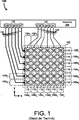
1 zeigt die Schaltkreise eines vorbekannten kapazitiven Berührungssystems 100 mit einem Sensorpanel 102 und einer Sensorsteuerung 104. Das Sensorpanel 102 umfasst mehrere Sensorzeilen 106 y–fy und mehrere Sensorspalten 108a x–fx, die entlang der y- bzw. x-Richtung nebeneinander gestellt sind. Jede der Sensorzeilen 106a y–fy umfasst ein diskretes Sensorelement 110, und jede der Sensorspalten 108a x–fx umfasst ein diskretes Sensorelement 112. Jedes Sensorelement 110 und 112 ist ein dünnes Muster aus ITO, das eine Reihe von verbundenen Rautenformen definiert, die sich völlig über die Berührungsoberfläche des Sensorpanel 102 in der x- bzw. y-Richtung erstrecken. Die Sensorsteuerung 104 umfasst eine erste Menge von Kanälen 114a y–fy und eine zweite Menge von Kanälen 116a x–fx. Jeder der Kanäle 114a y–fy ist über eine einer Menge von Signalleitungen 118 (z. B. Leiterbahnen, Drähte usw.) elektrisch mit dem Sensorelement 110 jeder jeweiligen der Sensorzeilen 106a y–fy verbunden. Ähnlich ist jeder der Kanäle 116a x–fx über eine einer Menge von Signalleitungen 120 elektrisch mit dem Sensorelement 112 jeder jeweiligen der Sensorspalten 108a x–fx verbunden. Während des Betriebs des Berührungssystems 100 wiederholt die Steuerung 104 kontinuierlich einen Zyklus des sequentiellen Scannens der Sensorzeilen 106a y–fy und -spalten 108a x–fx, um so die kapazitiven Zustände ihrer jeweiligen Sensorelemente 110 und 112 zu messen. Es gibt viele bekannte Verfahren zum Messen des kapazitiven Zustands eines Sensorelements, wie zum Beispiel Laden des Elements und Beobachten der Beruhigungszeit. Die Probemessung wird dann mit einem gespeicherten Wert verglichen, der den normalen kapazitiven Zustand der Elemente bei Abwesenheit eines Zielobjekts angibt. Wenn sich ein Zielobjekt einem bestimmten Bereich des Sensorpanels 102 nähert, bewirkt die natürliche Ladung des Zielobjekts, dass sich der kapazitive Zustand nahegelegener Sensorelemente 110 und 112 ändert. Algorithmen verarbeiten dann die kapazitive Änderung in den nahegelegenen Sensorelementen 110 und 112, um y- und x-Koordinaten zu erzeugen, die den Berührungsort angeben. Die Steuerung 104 führt diese Koordinaten dann der Host-Einrichtung zu, in der sie weiterer Verarbeitung unterzogen werden, um die Koordinaten auf die darunterliegende grafische Anzeigeeinrichtung abzubilden. 1 shows the circuits of a prior art capacitive touch system 100 with a sensor panel 102 and a sensor control 104 , The sensor panel 102 includes several sensor lines 106 y -f y and several sensor columns 108a x -f x juxtaposed along the y and x directions, respectively. Each of the sensor lines 106a y -f y comprises a discrete sensor element 110 , and each of the sensor columns 108a x -f x comprises a discrete sensor element 112 , Each sensor element 110 and 112 is a thin pattern of ITO that defines a series of connected diamond shapes that extend entirely across the touch surface of the sensor panel 102 extend in the x and y directions, respectively. The sensor control 104 includes a first set of channels 114a y -f y and a second set of channels 116a x -f x . Each of the channels 114a y -f y is over one of a set of signal lines 118 (eg, traces, wires, etc.) electrically to the sensor element 110 each of the respective sensor lines 106a y -f y connected. Similar is each of the channels 116a x -f x over one of a set of signal lines 120 electrically with the sensor element 112 each of the respective sensor columns 108a x -f x connected. During operation of the touch system 100 repeats the control 104 continuously one cycle of the sequential scanning of the sensor lines 106a y -f y and columns 108a x -f x , so the capacitive states of their respective sensor elements 110 and 112 to eat. There are many known methods for measuring the capacitive state of a sensor element, such as charging the element and observing the settling time. The sample measurement is then compared to a stored value indicating the normal capacitive state of the elements in the absence of a target object. When a target object reaches a certain area of the sensor panel 102 The natural charge of the target causes the capacitive state of nearby sensor elements to approach 110 and 112 changes. Algorithms then process the capacitive change in the nearby sensor elements 110 and 112 to generate y and x coordinates indicating the touch location. The control 104 then passes these coordinates to the host device, where they undergo further processing to map the coordinates to the underlying graphical display device.
Obwohl das vorbekannte kapazitive Berührungssystem 100 gegenüber resistiven Berührungssystemen Vorteile hat, gibt es weiterhin mehrere Probleme. Zum Beispiel weist ITO einen relativ hohen Widerstand auf, wodurch der Länge der Sensorelemente 110 und 112 Beschränkungen auferlegt werden. Mit zunehmendem Reihenwiderstand eines kapazitiven Sensorelements nimmt im Allgemeinen die Berührungsempfindlichkeit ab. Da der Reihenwiderstand proportional mit der Länge eines Elements zunimmt, müssen die Sensorelemente 110 und 112 relativ kurz sein, um einen annehmbaren Empfindlichkeitsgrad zu erzielen. Folglich eignet sich die Gestaltung des Berührungssystems 100 nicht für die Verwendung in Anwendungen, die große Anzeigeschirme verwenden. Obwohl der Reihenwiderstand durch Vergrößern der Fläche des Karomusters verringert werden kann, verringert dies die Sensorauflösung eines Sensorpanels. Außerdem kann der Reihenwiderstand durch Verwendung einer ITO-Schicht mit geringem Oberflächenwiderstand verringert werden, aber dadurch verringert sich die Transparenz der Sensorelemente, und die Sensorelemente werden sichtbar.Although the prior art capacitive touch system 100 There are still several problems with resistive contact systems. For example, ITO has a relatively high resistance, thereby increasing the length of the sensor elements 110 and 112 Restrictions are imposed. As the series resistance of a capacitive sensing element increases, touch sensitivity generally decreases. Since the series resistance increases proportionally with the length of an element, the sensor elements must 110 and 112 be relatively short to achieve an acceptable level of sensitivity. Consequently, the design of the touch system is suitable 100 not for use in applications that use large display screens. Although the series resistance can be reduced by increasing the area of the check pattern, this reduces the sensor resolution of a sensor panel. In addition, the series resistance can be reduced by using an ITO layer with low surface resistance, but this reduces the transparency of the sensor elements and makes the sensor elements visible.
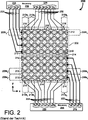
2 zeigt ein vorbekanntes kapazitives Berührungssystem 200, das sich an die durch den hohen Widerstand von ITO auferlegten Größen- und Auflösungsbeschränkungen wendet. Das System 200 umfasst ein Sensorpanel 202, eine erste Sensorsteuerung 204 und eine zweite Sensorsteuerung 206. Das Sensorpanel 202 umfasst mehrere Sensorzeilen 208a y–hy, die sich in der x-Richtung erstrecken. Das Sensorpanel 202 umfasst ferner mehrere Sensorspalten 210a x–gx, die sich in der y-Richtung erstrecken. Jede der Sensorzeilen 208a y–hy umfasst ein jeweiliges diskretes Sensorelement 212, und jede der Sensorspalten 210a x–gx umfasst zwei diskrete Sensorelemente 214 und 216. Die Sensorsteuerung 204 umfasst eine erste Menge von Kanälen 218a y–dy und eine zweite Menge von Kanälen 220a x–gx. Jeder der Kanäle 218a y–dy ist über eine jeweilige Menge von Signalleitungen 222 elektrisch mit einem jeweiligen Sensorelement 212 einer jeweiligen Zeile 208a y–hy verbunden. Ähnlich ist jeder der Kanäle 220 über eine jeweilige der Signalleitungen 224 elektrisch mit einem der ersten Sensorelemente 214 einer jeweiligen Sensorspalte 210a x–gx verbunden. Die Sensorsteuerung 206 umfasst eine erste Menge von Kanälen 226e y–hy und eine zweite Menge von Kanälen 228a x–gx. Jeder der Kanäle 226e y–hy ist über eine jeweilige der Signalleitungen 230 elektrisch mit einem jeweiligen Sensorelement 212 einer jeweiligen Zeile 208e y–hy verbunden. Ähnlich ist jeder der Kanäle 228a x–gx über eine jeweilige der Signalleitungen 232 elektrisch mit einem zweiten Sensorelement 216 einer jeweiligen der Sensorspalten 210a x–gx verbunden. Die Funktionsweise des Systems 200 ist der des Berührungssystems 100 ähnlich, mit der Ausnahme, dass das System 200 größere Schirmflächen unterstützen kann, weil jede der Sensorspalten 210a x–gx zwei Sensorelemente (d. h. die Sensorelemente 214 und 216) umfasst, statt einer einzigen Sensorspalte, die sich über die gesamte y-Distanz des Panels 202 erstreckt. Somit kann die y-Distanz des Panels 202 zweimal so lang wie die des Panel 102 sein. 2 shows a prior art capacitive touch system 200 , which addresses the size and resolution constraints imposed by ITO's high resistance. The system 200 includes a sensor panel 202 , a first sensor control 204 and a second sensor control 206 , The sensor panel 202 includes several sensor lines 208a y -h y extending in the x direction. The sensor panel 202 further includes a plurality of sensor gaps 210a x -g x extending in the y direction. Each of the sensor lines 208a y -h y comprises a respective discrete sensor element 212 , and each of the sensor columns 210a x -g x comprises two discrete sensor elements 214 and 216 , The sensor control 204 includes a first set of channels 218a y -d y and a second set of channels 220a x -g x . Each of the channels 218a y -d y is over a respective set of signal lines 222 electrical with a respective sensor element 212 a respective line 208a y -h y connected. Similar is each of the channels 220 via a respective one of the signal lines 224 electrically with one of the first sensor elements 214 a respective sensor column 210a x -g x connected. The sensor control 206 includes a first set of channels 226e y -h y and a second set of channels 228a x -g x . Each of the channels 226e y -h y is over a respective one of the signal lines 230 electrically with a respective sensor element 212 a respective line 208e y -h y connected. Similar is each of the channels 228a x -g x over a respective one of the signal lines 232 electrically with a second sensor element 216 a respective one of the sensor columns 210a x -g x connected. The functioning of the system 200 is that of the touch system 100 similar, except that the system 200 larger screen areas can support, because each of the sensor columns 210a x -g x two sensor elements (ie the sensor elements 214 and 216 ), instead of a single sensor column, extending over the entire y-distance of the panel 202 extends. Thus, the y-distance of the panel 202 twice as long as the panel 102 be.
Obwohl das System 200 eine größere Schirmfläche als das Berührungssystem 100 unterstützen kann, gibt es immer noch Probleme bei der Gestaltung. Zum Beispiel muss die x-Distanz des Panels 202 immer noch relativ kurz sein, weil jede der Sensorzeilen 208a y–hy nur ein einziges Sensorelement 212 umfasst, das sich über die gesamte x-Distanz erstreckt. Folglich lockert die Gestaltung des Systems 200 nur die Beschränkungen bezüglich der y-Länge des Panels 202 und deshalb existieren die Beschränkungen in der x-Richtung weiter. Als ein weiteres Beispiel weisen die Steuerungen 204 und 206 zusammen eine relativ große Anzahl von Kanälen auf (d. h. 218a y–dy, 220a x–gx, 226e y–hy und 228a x–gx), um die kapazitiven Zustände der Sensorelemente 212, 214 und 216 zu beschaffen. Anders ausgedrückt, weist das System 200 ein hohes Verhältnis von Kanal zu Sensorelement auf. Mit zunehmender Anzahl erforderlicher Kanäle und deshalb Kanalverbindungen nimmt natürlich die Gesamtzuverlässigkeit des Systems 200 ab. Darüber hinaus wird die Herstellung und Montage des Systems 200 durch die hohe Anzahl von Kanälen auch kostspielig, weil nur Steuerungen verwendet werden können, die hohe Kanalzahlen unterstützen.Although the system 200 a larger screen area than the touch system 100 there are still problems with the design. For example, the x-distance of the panel must be 202 still be relatively short, because each of the sensor lines 208a y -h y only a single sensor element 212 which extends over the entire x-distance. Consequently, the design of the system relaxes 200 only the restrictions on the y-length of the panel 202 and therefore the restrictions in the x-direction continue to exist. As another example, the controllers 204 and 206 together a relatively large number of channels (ie 218a y -d y , 220a x -g x , 226e y -h y and 228a x -g x ) to the capacitive states of the sensor elements 212 . 214 and 216 to get. In other words, the system rejects 200 a high ratio of channel to sensor element. As the number of channels required and therefore channel connections increases, so does the overall reliability of the system 200 from. In addition, the manufacture and installation of the system 200 because of the high number of channels also expensive, because only controllers can be used that support high channel numbers.
Es wird deshalb ein kapazitiver Berührungssystementwurf benötigt, der in Verbindung mit größeren Anzeigeschirmen verwendet werden kann. Außerdem wird ein kapazitiver Berührungssystementwurf benötigt, der die Berührungsempfindlichkeit verbessert, ohne die optische Klarheit aufzuopfern und/oder die Sensorauflösung zu verringern. Außerdem wird ein kapazitives Berührungssystem benötigt, das ein kleineres Verhältnis von Kanal zu Sensorelement aufweist. Außerdem wird ein kapazitives Berührungssystem benötigt, das eine höhere Zuverlässigkeit besitzt und dessen Herstellung weniger kostet.It therefore requires a capacitive touch system design that can be used in conjunction with larger display screens. In addition, a capacitive touch system design is needed that improves touch sensitivity without sacrificing optical clarity and / or reducing sensor resolution. In addition, a capacitive contact system is needed, which has a smaller ratio of channel to sensor element. In addition, a capacitive touch system is needed, which has a higher reliability and its production costs less.
KURZFASSUNGSHORT VERSION
Die vorliegende Erfindung überwindet die mit dem Stand der Technik verbundenen Probleme durch Bereitstellung eines kapazitiven Berührungssystems, das Folgendes umfasst: eine erste Steuerung mit mehreren Kanälen, eine erste Sensorzeile mit einem ersten diskreten Sensorelement und einem zweiten diskreten Sensorelement, eine zweite Sensorzeile mit einem ersten diskreten Sensorelement und einem zweiten diskreten Sensorelement, eine erste Sensorspalte, eine zweite Sensorspalte und eine erste Signalleitung, die einen Kanal der mehreren Kanäle der Steuerung elektrisch sowohl mit dem ersten als auch dem zweiten diskreten Sensorelement der ersten Sensorzeile koppelt.The present invention overcomes the problems associated with the prior art by providing a capacitive touch system comprising: a first multi-channel controller; a first sensor row having a first discrete sensor element and a second discrete sensor element; a second sensor line having a first discrete one Sensor element and a second discrete sensor element, a first sensor column, a second sensor column and a first signal line, which electrically couples a channel of the plurality of channels of the controller with both the first and the second discrete sensor element of the first sensor line.
Bei einer konkreten Ausführungsform umfasst das System ferner eine zweite Steuerung mit mehreren Kanälen. Bei einer konkreteren Ausführungsform umfasst das System ferner eine zweite Signalleitung, die einen ersten Kanal der zweiten Steuerung elektrisch sowohl mit dem ersten diskreten Sensorelement der zweiten Sensorzeile als auch dem zweiten diskreten Sensorelement der zweiten Sensorzeile koppelt. Bei einer noch konkreteren Ausführungsform umfasst die erste Sensorspalte ein erstes diskretes Sensorelement und ein zweites diskretes Sensorelement, die erste Steuerung umfasst einen zweiten Kanal, der über eine dritte Signalleitung elektrisch mit dem ersten diskreten Sensorelement der ersten Sensorspalte gekoppelt ist, und die zweite Steuerung umfasst einen zweiten Kanal, der elektrisch über eine vierte Signalleitung mit dem zweiten diskreten Sensorelement der erste Sensorspalte gekoppelt ist. Bei einer konkreteren Ausführungsform umfasst die zweite Sensorspalte ein erstes diskretes Sensorelement und ein zweites diskretes Sensorelement, die erste Steuerung umfasst einen dritten Kanal, der elektrisch über eine fünfte Signalleitung mit dem ersten diskreten Sensorelement der zweiten Sensorspalte gekoppelt ist, und die zweite Steuerung umfasst einen dritten Kanal, der elektrisch über eine sechste Signalleitung mit dem zweiten diskreten Sensorelement der zweiten Sensorspalte gekoppelt ist.In a particular embodiment, the system further includes a second multi-channel controller. In a more specific embodiment, the system further comprises a second signal line electrically coupling a first channel of the second controller to both the first discrete sensor element of the second sensor row and the second discrete sensor element of the second sensor row. In a more specific embodiment, the first sensor column includes a first discrete sensor element and a second discrete sensor element, the first controller includes a second channel electrically coupled to the first discrete sensor element of the first sensor column via a third signal line, and the second controller comprises one second channel, which is electrically coupled via a fourth signal line to the second discrete sensor element of the first sensor column. In a more specific embodiment, the second sensor column includes a first discrete sensor element and a second discrete sensor element, the first controller comprises a third channel electrically coupled to the first discrete sensor element of the second sensor column via a fifth signal line, and the second controller comprises a third one Channel, which is electrically coupled via a sixth signal line to the second discrete sensor element of the second sensor column.
Bei einer anderen konkreten Ausführungsform umfasst das System ferner eine zweite Steuerung mit einem ersten Kanal und einem zweiten Kanal, die erste Steuerung umfasst einen zweiten Kanal, die erste Sensorspalte umfasst ein erstes diskretes Sensorelement und ein zweites diskretes Sensorelement und die zweite Sensorspalte umfasst ein erstes diskretes Sensorelement und ein zweites diskretes Sensorelement. Bei einer konkreteren Ausführungsform ist der erste Kanal der ersten Steuerung elektrisch über eine erste Signalleitung sowohl mit dem ersten diskreten Sensorelement als auch dem zweiten diskreten Sensorelement der ersten Sensorzeile verbunden. Der erste Kanal der zweiten Steuerung ist elektrisch über eine zweite Signalleitung sowohl mit dem ersten diskreten Sensorelement als auch dem zweiten diskreten Sensorelement der zweiten Sensorzeile verbunden. Der zweite Kanal der ersten Steuerung ist elektrisch über eine dritte Signalleitung sowohl mit dem ersten diskreten Sensorelement als auch dem zweiten diskreten Sensorelement der ersten Sensorspalte verbunden. Der zweite Kanal der zweiten Steuerung ist elektrisch über eine vierte Signalleitung sowohl mit dem ersten diskreten Sensorelement als auch dem zweiten diskreten Sensorelement der zweiten Sensorspalte verbunden.In another specific embodiment, the system further comprises a second controller having a first channel and a second channel, the first controller comprises a second channel, the first sensor column comprises a first discrete sensor element and a second discrete sensor element, and the second sensor column comprises a first discrete one Sensor element and a second discrete sensor element. In a more concrete embodiment, the first channel of the first controller is electrically connected to both via a first signal line the first discrete sensor element and the second discrete sensor element of the first sensor line connected. The first channel of the second controller is electrically connected via a second signal line to both the first discrete sensor element and the second discrete sensor element of the second sensor line. The second channel of the first controller is electrically connected via a third signal line to both the first discrete sensor element and the second discrete sensor element of the first sensor column. The second channel of the second controller is electrically connected via a fourth signal line to both the first discrete sensor element and the second discrete sensor element of the second sensor column.
Bei einer anderen konkreteren Ausführungsform ist der erste Kanal der ersten Steuerung elektrisch über eine erste Signalleitung sowohl mit dem ersten als auch dem zweiten diskreten Sensorelement der ersten Sensorzeile gekoppelt, der zweite Kanal der ersten Steuerung ist elektrisch über eine zweite Signalleitung sowohl mit dem ersten als auch dem zweiten diskreten Sensorelement der zweiten Sensorzeile gekoppelt, der erste Kanal der ersten Steuerung ist elektrisch über eine dritte Signalleitung sowohl mit dem ersten als auch dem zweiten diskreten Sensorelement der ersten Sensorspalte gekoppelt und der zweite Kanal der zweiten Steuerung ist elektrisch über eine vierte Signalleitung sowohl mit dem ersten als auch dem zweiten diskreten Sensorelement der zweiten Sensorspalte gekoppelt.In another more concrete embodiment, the first channel of the first controller is electrically coupled to both the first and second discrete sensor elements of the first sensor line via a first signal line, the second channel of the first controller is electrically coupled to both the first and second signal lines coupled to the second discrete sensor element of the second sensor row, the first channel of the first controller is electrically coupled via a third signal line to both the first and the second discrete sensor element of the first sensor column and the second channel of the second controller is electrically connected both via a fourth signal line coupled to the first and the second discrete sensor element of the second sensor column.
Bei einer weiteren konkreten Ausführungsform umfasst die erste Sensorzeile ein erstes diskretes Sensorelement und ein zweites diskretes Sensorelement, die zweite Sensorzeile umfasst ein erstes diskretes Sensorelement und ein zweites diskretes Sensorelement, die erste Spalte umfasst ein erstes und zweites diskretes Sensorelement und die zweite Spalte umfasst ein erstes diskretes Sensorelement und ein zweites diskretes Sensorelement. Ferner umfasst die erste Steuerung einen ersten Kanal, einen zweiten Kanal, einen dritten Kanal und einen vierten Kanal. Der erste Kanal ist elektrisch über eine erste Signalleitung sowohl mit dem ersten als auch dem zweiten diskreten Sensorelement der ersten Sensorzeile gekoppelt, der zweite Kanal ist elektrisch über eine zweite Signalleitung sowohl mit dem ersten als auch dem zweiten diskreten Sensorelement der zweiten Sensorzeile gekoppelt, der dritte Kanal ist elektrisch über eine dritte Signalleitung sowohl mit dem ersten als auch dem zweiten diskreten Sensorelement der ersten Sensorspalte gekoppelt und der vierte Kanal ist elektrisch über eine vierte Signalleitung sowohl mit dem ersten als auch dem zweiten diskreten Sensorelement der zweiten Sensorspalte gekoppelt.In a further specific embodiment, the first sensor line comprises a first discrete sensor element and a second discrete sensor element, the second sensor line comprises a first discrete sensor element and a second discrete sensor element, the first column comprises a first and second discrete sensor element and the second column comprises a first discrete sensor element and a second discrete sensor element. Furthermore, the first controller comprises a first channel, a second channel, a third channel and a fourth channel. The first channel is electrically coupled via a first signal line to both the first and second discrete sensor elements of the first sensor row, the second channel is electrically coupled via a second signal line to both the first and second discrete sensor elements of the second sensor row, the third channel The channel is electrically coupled via a third signal line to both the first and second discrete sensor elements of the first sensor column, and the fourth channel is electrically coupled via a fourth signal line to both the first and second discrete sensor elements of the second sensor column.
Bei den beispielhaften Ausführungsformen werden die diskreten Sensorelemente aus einem transparenten leitfähigen Material, wie zum Beispiel Indiumzinnoxid, gebildet. Außerdem umfasst bei den beispielhaften Ausführungsformen jedes diskrete Sensorelement mehrere Rautenformen, die in Reihe geschaltet sind. Zusätzlich sind eine erste Menge von diskreten Sensorelementen und eine zweite Menge von diskreten Sensorelementen in einer überlagerten Beziehung angeordnet, wobei ein transparentes und elektrisch isolierendes Material zwischen den beiden Mengen (z. B. den Sensorzeilen und den Sensorspalten) von diskreten Sensorelementen angeordnet ist.In the exemplary embodiments, the discrete sensor elements are formed of a transparent conductive material, such as indium tin oxide. Additionally, in the exemplary embodiments, each discrete sensor element includes a plurality of diamond shapes connected in series. In addition, a first set of discrete sensor elements and a second set of discrete sensor elements are arranged in a superimposed relationship with a transparent and electrically insulating material disposed between the two sets (eg, the sensor rows and the sensor columns) of discrete sensor elements.
Bei den beispielhaften Ausführungsformen handelt es sich bei mindestens einigen Teilen der Sensorelemente um offenendige Elektroden, die elektrisch parallel mit den Kanälen der Steuerungen verbunden sind.In the exemplary embodiments, at least some portions of the sensor elements are open ended electrodes that are electrically connected in parallel with the channels of the controllers.
Gemäß einem Verfahren zum Detektieren einer Berührung werden der kapazitive Zustand des ersten diskreten Sensorelements und des zweiten diskreten Sensorelements der ersten Sensorzeile gleichzeitig an einem gemeinsamen Knoten gemessen.According to a method for detecting a touch, the capacitive state of the first discrete sensor element and the second discrete sensor element of the first sensor line are simultaneously measured at a common node.
KURZE BESCHREIBUNG DER ZEICHNUNGENBRIEF DESCRIPTION OF THE DRAWINGS
Die vorliegende Erfindung wird mit Bezug auf die folgenden Zeichnungen beschrieben, in denen gleiche Bezugszahlen im Wesentlichen ähnliche Elemente bezeichnen.The present invention will be described with reference to the following drawings in which like reference numerals denote substantially similar elements.
1 ist ein Diagramm eines vorbekannten kapazitiven Berührungssystems; 1 Fig. 12 is a diagram of a prior art capacitive touch system;
2 ist ein Diagramm eines anderen vorbekannten kapazitiven Berührungssystems; 2 Fig. 12 is a diagram of another prior art capacitive touch system;
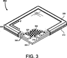
3 ist eine teilweise weggeschnittene perspektivische Ansicht eines kapazitiven Berührungssystems, das in eine Hosteinrichtung integriert gezeigt ist, gemäß einer Ausführungsform der vorliegenden Erfindung; 3 Fig. 12 is a partially cut away perspective view of a capacitive touch system shown integrated into a host device according to an embodiment of the present invention;
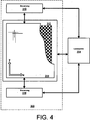
4 ist ein Blockdiagramm der elektrischen Kommunikation zwischen dem kapazitiven Berührungssystem von 3 und einer Leiterplatte der Hosteinrichtung; 4 is a block diagram of the electrical communication between the capacitive touch system of 3 and a circuit board of the host device;
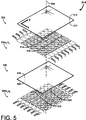
5 ist eine explodierte perspektivische Ansicht eines Sensorpanels des kapazitiven Berührungssystems von 3; 5 is an exploded perspective view of a sensor panel of the capacitive touch system of 3 ;
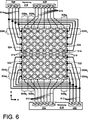
6 ist ein Diagramm der elektrischen Verbindungen zwischen einem Sensorpanel, einer ersten Steuerung und einer zweiten Steuerung; und 6 Fig. 12 is a diagram of the electrical connections between a sensor panel, a first controller, and a second controller; and
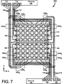
7 ist ein Diagramm der elektrischen Verbindungen zwischen einem Sensorpanel, einer alternativen ersten Steuerung und einer alternativen zweiten Steuerung gemäß einer anderen Ausführungsform der vorliegenden Erfindung. 7 FIG. 12 is a diagram of the electrical connections between a sensor panel, an alternative first controller, and an alternative second controller according to another embodiment of the present invention. FIG.
AUSFÜHRLICHE BESCHREIBUNGDETAILED DESCRIPTION
Die vorliegende Erfindung überwindet die mit dem Stand der Technik verbundenen Probleme, indem ein kapazitives Berührungssystem bereitgestellt wird, das größere Anzeigegrößen unterstützen kann. In der folgenden Beschreibung werden zahlreiche spezifische Einzelheiten dargelegt (z. B. Anzahl der Sensorzeilen und -spalten, spezifische Sensorelementmuster usw.), um ein umfassendes Verständnis der Erfindung zu gewährleisten. Für den Fachmann ist jedoch erkennbar, dass die Erfindung außerhalb dieser spezifischen Einzelheiten ausgeübt werden kann. In anderen Fällen wurden Einzelheiten wohlbekannter Sensordaten-Beschaffungspraktiken (z. B. Rauschfilterung, Signalverstärkung, Multiplexen, Eigenkapazitätsmessung usw.) und Komponenten weggelassen, um die vorliegende Erfindung so nicht unnötig zu verdecken.The present invention overcomes the problems associated with the prior art by providing a capacitive touch system that can support larger display sizes. In the following description, numerous specific details are set forth (eg, number of sensor rows and columns, specific sensor element patterns, etc.) to provide a thorough understanding of the invention. However, it will be apparent to those skilled in the art that the invention may be practiced outside of these specific details. In other instances, details of well-known sensor data acquisition practices (eg, noise filtering, signal amplification, multiplexing, self-capacitance measurement, etc.) and components have been omitted so as not to unnecessarily obscure the present invention.
3 zeigt eine perspektivische Ansicht eines kapazitiven Berührungssystems 300 gemäß einer Ausführungsform der vorliegenden Erfindung. In diesem Beispiel ist das kapazitive Berührungssystem 300 das primäre Benutzereingabe-/-ausgabesystem einer Hosteinrichtung 302, die eine kapazitive Berührungssystem-Hosteinrichtung repräsentiert (z. B. Tablet-Computer, PDA, MP3-Player, Mobiltelefon usw.). Die Host-Einrichtung 302 umfasst ferner eine Leiterplatte 304 und ein Gehäuse 306. Die Leiterplatte 304 repräsentiert die Hauptschaltkreise der Hosteinrichtung 302, die allgemeine Datenverarbeitungsinformationen ausführen, wie etwa Datenkommunikation, -verarbeitung, -speicherung usw. Das Gehäuse 306 umfasst eine Einfassung 308 und eine hintere Abdeckung 310, die von entgegengesetzten Seiten der Einrichtung 302 aus miteinander gekoppelt sind, um so die inneren Komponenten der Einrichtung 302 zu schützen, während außerdem direkte Interaktion zwischen einem Benutzer und dem kapazitiven Berührungssystem 300 gestattet wird. Für den Fachmann ist erkennbar, dass außer dem kapazitiven Berührungssystem 300 spezifische Einzelheiten in Bezug auf die Hosteinrichtung 302 abhängig von der Anwendung variieren werden und nicht besonders relevant für das Vorliegende sind. Die Leiterplatte 304 und das Gehäuse 306 sind deshalb nur von repräsentativer Beschaffenheit. 3 shows a perspective view of a capacitive touch system 300 according to an embodiment of the present invention. In this example, the capacitive touch system is 300 the primary user input / output system of a host device 302 representing a capacitive touch-system host device (e.g., tablet computer, PDA, MP3 player, mobile phone, etc.). The host facility 302 further includes a circuit board 304 and a housing 306 , The circuit board 304 represents the main circuits of the host device 302 which perform general data processing information such as data communication, processing, storage, etc. The housing 306 includes a border 308 and a back cover 310 that are from opposite sides of the institution 302 are coupled together so as to internal components of the device 302 while also providing direct interaction between a user and the capacitive touch system 300 is allowed. It will be appreciated by those skilled in the art that except for the capacitive touch system 300 specific details regarding the host device 302 vary depending on the application and are not particularly relevant to the present. The circuit board 304 and the case 306 are therefore only of a representative nature.
Das kapazitive Berührungssystem 300 umfasst eine grafische Anzeigeeinrichtung 312, ein kapazitives Sensorpanel 314 und zwei Steuerungen 316 und 318 (beide Steuerungen sind in 5 gezeigt). Die grafische Anzeigeeinrichtung 312 ist zum Beispiel eine Flüssigkristallanzeige (LCD) mit einer oberen Oberfläche 320, die einen Schirm 322 zum Anzeigen von grafischen Ausgabeinformationen definiert. Ferner ist die grafische Anzeigeeinrichtung 312 auf der Leiterplatte 304 angebracht und elektrisch mit dieser gekoppelt, um so Datenkommunikation zwischen ihnen zu ermöglichen. Das Sensorpanel 314 ist eine transparente kapazitive Berührungserfassungseinrichtung, die Benutzereingaben von einem Zielobjekt (z. B. Finger, Stift usw.) empfängt, indem die Anwesenheit seiner elektrischen Ladung an spezifischen Orten in einer zweidimensionalen xy-Region detektiert wird. Das Sensorpanel 314 und die grafische Anzeigeeinrichtung 312 sind in einer gestapelten Beziehung miteinander gekoppelt, wobei das Sensorpanel 314 auf der oberen Oberfläche 320 über dem Schirm 322 angebracht ist. Folglich werden grafische Ausgabeinformationen von dem Schirm 322 durch das Sensorpanel 314 angezeigt. Jede der Steuerungen 316 und 318 ist zum Beispiel ein Mikrocontrollerchip, der Sensordaten von einer jeweiligen verschiedenen Region des Sensorpanels 314 beschafft. Ferner sind die Steuerungen 316 und 318 elektrisch mit der Leiterplatte 304 gekoppelt, so dass Sensordaten, die den Ort des Zielobjekts angeben, zu den Verarbeitungsschaltkreisen der Leiterplatte 304 übermittelt und von diesen weiter verarbeitet werden können. Für den Fachmann ist erkennbar, dass die spezifischen Orte der Steuerungen 316 und 318 für die vorliegende Erfindung nicht besonders relevant sind. Die elektrischen Verbindungen zwischen den Steuerungen 316, 318 und dem Sensorpanel 314 sind jedoch besonders wichtig und werden deshalb nachfolgend im Einzelnen mit Bezug auf 6 besprochen.The capacitive touch system 300 includes a graphical display device 312 , a capacitive sensor panel 314 and two controllers 316 and 318 (both controls are in 5 shown). The graphic display device 312 For example, a liquid crystal display (LCD) having a top surface 320 holding a screen 322 Defined for displaying graphical output information. Further, the graphic display device is 312 on the circuit board 304 attached and electrically coupled to it so as to allow data communication between them. The sensor panel 314 is a transparent capacitive touch sensing device that receives user inputs from a target object (eg, finger, stylus, etc.) by detecting the presence of its electrical charge at specific locations in a two-dimensional xy region. The sensor panel 314 and the graphic display device 312 are coupled together in a stacked relationship with the sensor panel 314 on the upper surface 320 over the screen 322 is appropriate. As a result, graphic output information from the screen becomes 322 through the sensor panel 314 displayed. Each of the controls 316 and 318 For example, a microcontroller chip is the sensor data from a respective different region of the sensor panel 314 procured. Further, the controls 316 and 318 electrically with the circuit board 304 coupled, so that sensor data indicating the location of the target object to the processing circuitry of the circuit board 304 transmitted and processed by them. It will be apparent to those skilled in the art that the specific locations of the controllers 316 and 318 are not particularly relevant to the present invention. The electrical connections between the controllers 316 . 318 and the sensor panel 314 however, are particularly important and will therefore be discussed in detail below with reference to 6 discussed.
4 ist ein Blockdiagramm der elektrischen Kommunikation zwischen dem Berührungssystem 300 und einer Leiterplatte 304 der Hosteinrichtung 302. Wie gezeigt kommunizieren die Steuerung 316 und 318 mit dem Sensorpanel 314. Genauer gesagt beschafft jede der Steuerungen 316 und 318 Sensormessungen von einer anderen Region des Sensorpanel 314. Die Steuerungen 316 und 318 verarbeiten die Messungen und erzeugen Daten, die den Ort des Zielobjekts angeben. Dann werden die Daten in ein Format umgesetzt, das zu der Leiterplatte 304 übermittelt werden kann. Die Leiterplatte 304 empfängt die Positionsdaten von beiden Steuerungen 316 und 318 zur weiteren Verarbeitung. Die Leiterplatte 304 kommuniziert außerdem mit der grafischen Anzeigeeinrichtung 312, um Daten und Anweisungen bereitzustellen, die grafische Informationen angeben, die durch den Schirm 322 anzuzeigen sind. Obwohl es nicht gezeigt ist, würde typischerweise ein Anzeigetreiber Kommunikation zwischen der Leiterplatte 304 und der grafischen Anzeigeeinrichtung 312 ermöglichen. Die spezifischen mit der grafischen Anzeigeeinrichtung 312 und wie zuvor der Leiterplatte 304 assoziierten Einzelheiten sind für die vorliegende Erfindung nicht besonders relevant und werden somit nicht ausführlicher offenbart. 4 is a block diagram of the electrical communication between the touch system 300 and a circuit board 304 the host device 302 , As shown, the controller communicate 316 and 318 with the sensor panel 314 , More precisely, each of the controls procures 316 and 318 Sensor measurements from another region of the sensor panel 314 , The controls 316 and 318 process the measurements and generate data indicating the location of the target object. Then the data is converted into a format that is attached to the circuit board 304 can be transmitted. The circuit board 304 receives the position data from both controllers 316 and 318 for further processing. The circuit board 304 also communicates with the graphical display 312 to provide data and instructions that indicate graphical information passing through the screen 322 are to be displayed. Although not shown, typically a display driver would communicate between the circuit board 304 and the graphic display device 312 enable. The specific with the graphic display device 312 and as before the circuit board 304 associated details are for the present The invention is not particularly relevant and will therefore not be disclosed in more detail.
5 zeigt eine perspektivische Ansicht des Sensorpanels 314 entlang einer Achse 500 explodiert. Bei dieser konkreten Ausführungsform ist das Sensorpanel 314 eine transparente Verbundstruktur, die aus einem ersten Substrat 502, mehreren Sensorzeilen 504a y–hy, einem zweiten transparenten Substrat 506 und mehreren Sensorspalten 508a x–gx besteht. Wie gezeigt, ist das Substrat 502 über den Zeilen 504a y–hy angeordnet, die Zeilen 504a y–hy sind zwischen dem Substrat 502 und dem Substrat 506 angeordnet, das Substrat 506 ist zwischen den Zeilen 504a y–hy und den Spalten 508a x–gx angeordnet und die Spalten 508a x–gx sind unter dem Substrat 506 angeordnet. 5 shows a perspective view of the sensor panel 314 along an axis 500 exploded. In this particular embodiment, the sensor panel is 314 a transparent composite structure consisting of a first substrate 502 , several sensor lines 504a y -h y , a second transparent substrate 506 and several sensor columns 508a x -g x exists. As shown, the substrate is 502 over the lines 504a y -h y arranged the lines 504a y -h y are between the substrate 502 and the substrate 506 arranged the substrate 506 is between the lines 504a y -h y and the columns 508a x -g x arranged and the columns 508a x -g x are under the substrate 506 arranged.
Das Substrat 502 ist eine starre, transparente und elektrisch isolierende Struktur, wie zum Beispiel eine dünne Glasplatte. Ferner umfasst das Substrat 502 eine obere Oberfläche 510 und eine gegenüberliegende untere planare Oberfläche 512. Die obere Oberfläche 510 definiert eine planare Berührungsoberfläche, die während Benutzereingabeereignissen von einem Zielobjekt kontaktiert wird. Man beachte, dass zur Vermeidung von Verwirrung verschiedene Aspekte des Panels 314 mit Bezug auf eine zweidimensionale xy-Ebene, die auf der oberen Oberfläche 510 gezeigt ist, beschrieben werden.The substrate 502 is a rigid, transparent and electrically insulating structure, such as a thin glass plate. Furthermore, the substrate comprises 502 an upper surface 510 and an opposing lower planar surface 512 , The upper surface 510 defines a planar touch surface that is contacted by user input events from a target object. Note that to avoid confusion various aspects of the panel 314 with reference to a two-dimensional xy plane that is on the top surface 510 is shown.
Die Sensorzeilen 504a y–hy sind in der y-Richtung angeordnet und erstrecken sich in der x-Richtung über das Panel 314 der Gestalt, dass sich jede der Zeilen 504a y–hy an einem anderen y-Ort befindet. Jede der Sensorzeilen 504a y–hy umfasst ein erstes diskretes Sensorelement 514 und ein zweites diskretes Sensorelement 516, die sich von entgegengesetzten Richtungen aus zueinander erstrecken, der Gestalt, dass jedes eine andere Region derselben Zeile einnimmt. Obwohl jedes Paar von Sensorelementen 514 und 516 eine andere Region derselben Zeile einnimmt, sind sie ausgerichtet und entsprechen derselben y-Koordinate. Bei dieser konkreten Ausführungsform ist jedes der Sensorelemente 514 und 516 aus einem transparenten leitfähigen Material (z. B. ITO) zusammengesetzt, das auf dem Substrat 502 strukturiert wird, um eine Reihe von verbundenen Karoformen zu definieren, die entlang der x-Richtung angeordnet sind. Da die Sensorelemente 514 und 516 aus einem leitfähigen Material bestehen, besitzt jedes eine messbare Eigenkapazität, die sich bei Anwesenheiten eines Zielobjekts (z. B. eines Fingers, eines Stifts usw.) ändert.The sensor lines 504a y -h y are arranged in the y direction and extend across the panel in the x direction 314 the shape that is each of the lines 504a y -h y is in a different y-location. Each of the sensor lines 504a y -h y comprises a first discrete sensor element 514 and a second discrete sensor element 516 that extend from opposite directions to each other, the shape that each occupies a different region of the same line. Although every pair of sensor elements 514 and 516 If another region occupies the same line, they are aligned and correspond to the same y-coordinate. In this particular embodiment, each of the sensor elements 514 and 516 composed of a transparent conductive material (eg ITO), which is on the substrate 502 is patterned to define a series of connected caroforms arranged along the x-direction. Because the sensor elements 514 and 516 Each of them has a measurable intrinsic capacity which changes when a target object (eg, a finger, a stylus, etc.) is present.
Das Substrat 506 ist dem Substrat 502 insofern ähnlich, als dass es eine starre, transparente und elektrisch isolierende Struktur ist, wie zum Beispiel eine dünne Glasplatte. Ferner umfasst das Substrat 506 eine obere Oberfläche 518 und eine gegenüberliegende untere planare Oberfläche 520. Das Substrat 506 wirkt als isolierende Barriere zwischen den Sensorzeilen 504a y–hy und Sensorspalten 508a x–gx.The substrate 506 is the substrate 502 similar in that it is a rigid, transparent and electrically insulating structure, such as a thin glass plate. Furthermore, the substrate comprises 506 an upper surface 518 and an opposing lower planar surface 520 , The substrate 506 acts as an insulating barrier between the sensor lines 504a y -h y and sensor columns 508a x -g x .
Die Sensorspalten 508a x–gx sind entlang der x-Richtung beabstandet und erstrecken sich in der y-Richtung über das Panel 314, dergestalt, dass sich jede der Spalten 508a x–gx an einem anderen x-Ort befindet. Jede der Sensorspalten 508a x–gx umfasst ein erstes diskretes Sensorelement 522 und ein zweites diskretes Sensorelement 524, die sich von entgegengesetzten Richtungen aus zueinander erstrecken, dergestalt, dass jedes eine andere Region derselben Spalte einnimmt. Obwohl jedes Paar von Sensorelementen 522 und 524 eine andere Region derselben Spalte einnimmt, sind sie ausgerichtet, um derselben x-Koordinate zu entsprechen. Bei dieser konkreten Ausführungsform besteht jedes der Sensorelemente 522 und 524 aus einem transparenten leitfähigen Material (z. B. ITO), das auf dem Substrat 506 strukturiert wird, um eine Reihe von verbundenen Rautenformen zu definieren, die entlang der y-Richtung angeordnet sind. Wie die Sensorelemente 514 und 516 bestehen die Sensorelemente 522 und 524 auch aus einem leitfähigen Material und besitzen deshalb eine messbare Eigenkapazität, die sich bei Anwesenheit eines Zielobjekts ändert.The sensor columns 508a x -g x are spaced along the x-direction and extend across the panel in the y-direction 314 , so that each of the columns 508a x -g x is at a different x-location. Each of the sensor columns 508a x -g x comprises a first discrete sensor element 522 and a second discrete sensor element 524 extending from opposite directions to each other such that each occupies a different region of the same column. Although every pair of sensor elements 522 and 524 another region of the same column, they are aligned to correspond to the same x-coordinate. In this specific embodiment, each of the sensor elements 522 and 524 made of a transparent conductive material (eg ITO), which is on the substrate 506 is patterned to define a series of connected diamond shapes arranged along the y-direction. Like the sensor elements 514 and 516 consist of the sensor elements 522 and 524 also of a conductive material and therefore have a measurable intrinsic capacity, which changes in the presence of a target object.
Bei dieser konkreten Ausführungsform werden die Sensorzeilen 504 und Sensorspalten 508 durch Abscheiden einer ITO-Schicht direkt auf die untere Oberfläche 512 des Substrats 502 bzw. die untere Oberfläche 520 des Substrats 506 durch ein bestimmtes geeignetes Mittel, wie zum Beispiel Sputter-Abscheidung, gebildet. Dann wird die auf der Oberfläche 512 gebildete ITO-Schicht geätzt, um die Sensorelemente 514 und 516 zu definieren, und die auf der Oberfläche 520 gebildete ITO-Schicht wird geätzt, um die Sensorelemente 522 und 524 zu definieren. Nachdem die ITO-Schichten geätzt sind, werden die Substrate 502 und 506 in einer gestapelten Beziehung permanent aneinander gebondet, der Gestalt, dass die untere Oberfläche 512 des Substrats 502 mit darauf gebildeten Sensorzeilen 504 zum Beispiel über einen dazwischen angeordneten transparenten nichtleitfähigen Haftkleber (PSA) an die obere Oberfläche 518 des Substrats 506 gebondet wird. Ähnlich wird das Sensorpanel 314 dergestalt auf dem grafischen Display 312 angebracht, dass die untere Oberfläche 520 des Substrats 506 mit darauf gebildeten Sensorspalten 508 zum Beispiel über einen dazwischen angeordneten PSA an die obere Oberfläche 320 der grafischen Anzeigeeinrichtung 312 gebondet wird.In this particular embodiment, the sensor lines become 504 and sensor columns 508 by depositing an ITO layer directly on the lower surface 512 of the substrate 502 or the lower surface 520 of the substrate 506 formed by a certain suitable means, such as sputter deposition. Then that will be on the surface 512 formed ITO layer etched to the sensor elements 514 and 516 to define, and those on the surface 520 formed ITO layer is etched to the sensor elements 522 and 524 define. After the ITO layers are etched, the substrates become 502 and 506 permanently bonded together in a stacked relationship, the shape that the lower surface 512 of the substrate 502 with sensor lines formed thereon 504 for example via an interposed transparent non-conductive pressure sensitive adhesive (PSA) to the top surface 518 of the substrate 506 is bonded. The sensor panel becomes similar 314 in the same way on the graphic display 312 attached to the bottom surface 520 of the substrate 506 with sensor gaps formed thereon 508 for example, via an intermediate PSA to the upper surface 320 the graphical display device 312 is bonded.
6 ist ein Schaltbild der Schaltkreise zwischen dem Sensorpanel 314, der ersten Steuerung 316 und der zweiten Steuerung 318. Wie zuvor erwähnt, ist jede der Steuerungen 316 und 318 wirksam zum Steuern einer anderen Region des Berührungssensor-Panels 314. Genauer gesagt steuert die erste Steuerung 316 die Sensorzeilen 504a y–dy und jedes erste diskrete Sensorelement 522 der Sensorspalten 508a x–gx. Die Steuerung 318 steuert die Sensorzeilen 504e y–hy und jedes zweite diskrete Sensorelement 524 der Sensorspalten 508a x–gx. Die Steuerung 316 umfasst eine erste Menge von Kanälen 602a y–dy (eine Vielzahl von separaten Eingängen) und eine zweite Menge von Kanälen 604a x–gx (eine andere Vielzahl von separaten Eingängen). Ähnlich umfasst die Steuerung 318 eine erste Menge von Kanälen 606e y–hy und eine zweite Menge von Kanälen 608a x–gx. 6 is a circuit diagram of the circuits between the sensor panel 314 , the first controller 316 and the second controller 318 , As mentioned before, each of the controls 316 and 318 effective for controlling another region of the Touch sensor panels 314 , More precisely, the first controller controls 316 the sensor lines 504a y -d y and each first discrete sensor element 522 the sensor columns 508a x -g x . The control 318 controls the sensor lines 504e y -h y and every second discrete sensor element 524 the sensor columns 508a x -g x . The control 316 includes a first set of channels 602a y -d y (a plurality of separate inputs) and a second set of channels 604a x -g x (another variety of separate inputs). Similarly, the controller includes 318 a first set of channels 606e y -h y and a second set of channels 608a x -g x .
Die ersten Kanäle 602a y–dy der Steuerung 316 sind elektrisch über eine Menge von Signalleitungen 610 mit jeweiligen Sensorzeilen 504a y–dy verbunden. Genauer gesagt verbindet jede der Signalleitungen 610 einen der Kanäle 602a x–gx elektrisch mit dem ersten Sensorelement 514 und dem zweiten Sensorelement 516 einer jeweiligen der Zeilen 504a y–dy. Das heißt, der Kanal 602a y wird über eine erste der Signalleitungen 610 elektrisch mit beiden Sensorelementen 514 und 516 der jeweiligen Sensorzeile 504a y verbunden, Kanal 602b y wird über eine zweite der Signalleitungen 610 elektrisch mit beiden Sensorelementen 514 und 516 der jeweiligen Sensorzeile 504b y verbunden, Kanal 602c y wird über eine dritte der Signalleitungen 610 elektrisch mit beiden Sensorelementen 514 und 516 der jeweiligen Sensorzeilen 504c y verbunden und Kanal 602d y wird elektrisch über eine vierte der Signalleitungen 610 mit beiden Sensorelementen 514 und 516 der jeweiligen Sensorzeile 504d y verbunden. Dementsprechend teilen sich jedes Paar von Sensorelementen 514 und 516 der Sensorzeilen 504a y–dy einen gemeinsamen Knoten mit einem jeweiligen der Kanäle 602a y–dy.The first channels 602a y -d y of the controller 316 are electrical over a lot of signal lines 610 with respective sensor lines 504a y -d y connected. More specifically, each of the signal lines connects 610 one of the channels 602a x -g x electrically with the first sensor element 514 and the second sensor element 516 a respective one of the lines 504a y -d y . That is, the channel 602a y is via a first of the signal lines 610 electrically with both sensor elements 514 and 516 the respective sensor line 504a y connected, channel 602b y is via a second of the signal lines 610 electrically with both sensor elements 514 and 516 the respective sensor line 504b y connected, channel 602c y is via a third of the signal lines 610 electrically with both sensor elements 514 and 516 the respective sensor lines 504c y connected and channel 602d y becomes electrically via a fourth of the signal lines 610 with both sensor elements 514 and 516 the respective sensor line 504d y connected. Accordingly, each pair of sensor elements share 514 and 516 the sensor lines 504a y -d y a common node with a respective one of the channels 602a y -d y .
Die zweiten Kanäle 604a x–gx sind über eine Menge von Signalleitungen 612 elektrisch mit ersten Sensorelementen 522 der jeweiligen Sensorspalten 508a x–gx verbunden. Das heißt, Kanal 604a x ist elektrisch über eine erste der Signalleitungen 612 mit dem Sensorelement 522 der jeweiligen Sensorspalte 508a x verbunden, Kanal 604b x ist elektrisch über eine zweite der Signalleitungen 612 mit dem Sensorelement 522 der jeweiligen Sensorspalte 508b x verbunden, Kanal 604c x ist elektrisch über eine dritte der Signalleitungen 612 mit dem Sensorelement 522 der jeweiligen Sensorspalte 508c x verbunden, Kanal 604c x ist elektrisch über eine dritte der Signalleitungen 612 mit dem Sensorelement 522 der jeweiligen Sensorspalte 508c x verbunden, Kanal 604d x ist elektrisch über eine vierte der Signalleitungen 612 mit dem Sensorelement 522 der jeweiligen Sensorspalte 508d x verbunden, Kanal 604e x ist elektrisch über eine fünfte der Signalleitungen 612 mit dem Sensorelement 522 der jeweiligen Sensorspalte 508e x verbunden, Kanal 604f x ist elektrisch über eine sechste der Signalleitungen 612 mit dem Sensorelement 522 der jeweiligen Sensorspalte 508f x verbunden und Kanal 604g x ist elektrisch über eine siebte der Signalleitungen 612 mit dem Sensorelement 522 der jeweiligen Sensorspalte 508g x verbunden. Dementsprechend teilen sich die Kanäle 604a x–gx jeweils einen gemeinsamen Knoten mit einem jeweiligen der Sensorelemente 522.The second channels 604a x -g x are over a lot of signal lines 612 electrically with first sensor elements 522 the respective sensor columns 508a x -g x connected. That is, channel 604a x is electrically across a first of the signal lines 612 with the sensor element 522 the respective sensor column 508a x connected, channel 604b x is electrically via a second of the signal lines 612 with the sensor element 522 the respective sensor column 508b x connected, channel 604c x is electrically across a third of the signal lines 612 with the sensor element 522 the respective sensor column 508c x connected, channel 604c x is electrically across a third of the signal lines 612 with the sensor element 522 the respective sensor column 508c x connected, channel 604d x is electrically across a fourth of the signal lines 612 with the sensor element 522 the respective sensor column 508d x connected, channel 604e x is electrically across a fifth of the signal lines 612 with the sensor element 522 the respective sensor column 508e x connected, channel 604F x is electrically across a sixth of the signal lines 612 with the sensor element 522 the respective sensor column 508f x connected and channel 604g x is electrically across a seventh of the signal lines 612 with the sensor element 522 the respective sensor column 508g x connected. Accordingly, the channels divide 604a x -g x each have a common node with a respective one of the sensor elements 522 ,
Die ersten Kanäle 606e y–hy der Steuerung 318 sind über eine Menge von Signalleitungen 614 elektrisch mit jeweiligen Sensorzeilen 504e y–hy verbunden. Genauer gesagt verbindet jede der Signalleitungen 614 elektrisch einen der Kanäle 606e x–hx mit dem ersten Sensorelement 514 und dem zweiten Sensorelement 516 einer jeweiligen der Zeilen 504e y–hy. Das heißt, Kanal 606e y ist elektrisch über eine erste der Signalleitungen 614 mit beiden Sensorelementen 514 und 516 der jeweiligen Sensorzeile 504e y verbunden, Kanal 606f y ist elektrisch über eine zweite der Signalleitungen 614 mit beiden Sensorelementen 514 und 516 der jeweiligen Sensorzeile 504f y verbunden, Kanal 606g y ist elektrisch über eine dritte der Signalleitungen 614 mit beiden Sensorelementen 514 und 516 der jeweiligen Sensorzeile 504g y verbunden und Kanal 606h y ist elektrisch über eine vierte der Signalleitungen 614 mit beiden Sensorelementen 514 und 516 der jeweiligen Sensorzeile 504h y verbunden. Dementsprechend teilt sich jedes Paar von Sensorelementen 514 und 516 der Sensorzeilen 504e y–hy einen gemeinsamen Knoten mit einem jeweiligen der Kanäle 606e y–hy.The first channels 606e y -h y of the controller 318 are about a lot of signal lines 614 electrically with respective sensor lines 504e y -h y connected. More specifically, each of the signal lines connects 614 electrically one of the channels 606e x -h x with the first sensor element 514 and the second sensor element 516 a respective one of the lines 504e y -h y . That is, channel 606e y is electrically across a first of the signal lines 614 with both sensor elements 514 and 516 the respective sensor line 504e y connected, channel 606f y is electrically via a second of the signal lines 614 with both sensor elements 514 and 516 the respective sensor line 504f y connected, channel 606g y is electrically across a third of the signal lines 614 with both sensor elements 514 and 516 the respective sensor line 504g y connected and channel 606h y is electrically across a fourth of the signal lines 614 with both sensor elements 514 and 516 the respective sensor line 504h y connected. Accordingly, each pair of sensor elements splits 514 and 516 the sensor lines 504e y -h y one common node with a respective one of the channels 606e y -h y .
Die zweiten Kanäle 608a x–gx sind über eine Menge von Signalleitungen 616 elektrisch mit zweiten Sensorelementen 524 der jeweiligen Sensorspalten 508a x–gx verbunden. Das heißt, Kanal 608a x ist über eine erste der Signalleitungen 616 elektrisch mit dem Sensorelement 524 der jeweiligen Sensorspalte 508a x verbunden, Kanal 608b x ist über eine zweite der Signalleitungen 616 elektrisch mit dem Sensorelement 524 der jeweiligen Sensorspalte 508b x verbunden, Kanal 608c x ist über eine dritte der Signalleitungen 616 elektrisch mit dem Sensorelement 524 der jeweiligen Sensorspalte 508c x verbunden, Kanal 608c x ist über eine dritte der Signalleitungen 616 elektrisch mit dem Sensorelement 524 der jeweiligen Sensorspalte 508c x verbunden, Kanal 608d x ist über eine vierte der Signalleitungen 616 elektrisch mit dem Sensorelement 524 der jeweiligen Sensorspalte 508d x verbunden, Kanal 608e x ist über eine fünfte der Signalleitungen 616 elektrisch mit dem Sensorelement 524 der jeweiligen Sensorspalte 508e x verbunden, Kanal 608f x ist über eine sechste der Signalleitungen 616 elektrisch mit dem Sensorelement 524 der jeweiligen Sensorspalte 508f x verbunden und Kanal 608g x ist über eine siebte der Signalleitungen 616 elektrisch mit dem Sensorelement 524 der jeweiligen Sensorspalte 508g x verbunden. Dementsprechend teilen sich die Kanäle 608a x–gx jeweils einen gemeinsamen Knoten mit einem jeweiligen der Sensorelemente 524.The second channels 608a x -g x are over a lot of signal lines 616 electrically with second sensor elements 524 the respective sensor columns 508a x -g x connected. That is, channel 608a x is over a first of the signal lines 616 electrically with the sensor element 524 the respective sensor column 508a x connected, channel 608b x is over a second of the signal lines 616 electrically with the sensor element 524 the respective sensor column 508b x connected, channel 608c x is over a third of the signal lines 616 electrically with the sensor element 524 the respective sensor column 508c x connected, channel 608c x is over a third of the signal lines 616 electrically with the sensor element 524 the respective sensor column 508c x connected, channel 608d x is over a fourth of the signal lines 616 electrically with the sensor element 524 the respective sensor column 508d x connected, channel 608e x is over a fifth of the signal lines 616 electrically with the sensor element 524 the respective sensor column 508e x connected, channel 608f x is over a sixth of the signal lines 616 electrically with the sensor element 524 the respective sensor column 508f x connected and channel 608g x is over a seventh of the signal lines 616 electrically with the sensor element 524 the respective sensor column 508g x connected. Accordingly, the channels divide 608a x -g x each have a common node with a respective one of the sensor elements 524 ,
Während des Betriebs wird der kapazitive Zustand jeder einzelnen der Sensorzeilen 504a y–dy an einem jeweiligen der Kanäle 602a y–gy gemessen, der kapazitive Zustand jedes Sensorelements 522 der Spalten 508a x–gx wird an den jeweiligen Kanälen 604a x–gx gemessen, der kapazitive Zustand jeder einzelnen der Sensorzeilen 504e y–hy wird an einem jeweiligen der Kanäle 606e y–hy gemessen und der kapazitive Zustand jedes Sensorelements 524 der Spalten 508a x–gx wird an jeweiligen Kanälen 604a x–gx gemessen. Es folgt, dass, wenn ein Berührungsereignis auf der unteren Hälfte der Oberfläche 510 stattfindet, die an den Kanälen 602a y–dy und den Kanälen 604a x–gx erfassten Messungen einer y-Koordinate bzw. einer x-Koordinate entsprechen, die zusammen den Ort des Zielobjekts definieren. Wenn ein Berührungsereignis auf der oberen Hälfte der Oberfläche 510 stattfindet, entsprechen die an den Kanälen 606e y–hy und den Kanälen 608a x–gx erfassten Messungen einer y-Koordinate bzw. x-Koordinate, die den Zielobjektort angeben.During operation, the capacitive state of each one of the sensor lines becomes 504a y -d y at a respective one of the channels 602a y -g y measured, the capacitive state of each sensor element 522 the columns 508a x -g x will be on the respective channels 604a x -g x measured, the capacitive state of each of the sensor lines 504e y -h y is at a respective one of the channels 606e y -h y measured and the capacitive state of each sensor element 524 the columns 508a x -g x is on respective channels 604a x -g x measured. It follows that when a touch event on the lower half of the surface 510 taking place at the canals 602a y -d y and the channels 604a x -g x measurements correspond to a y-coordinate or an x-coordinate, which together define the location of the target object. If a touch event on the top half of the surface 510 takes place, correspond to the channels 606e y -h y and the channels 608a x -g x captured measurements of a y-coordinate or x-coordinate that indicate the target location.
Da sich jedes erste Sensorelement 514 einen gemeinsamen Knoten mit einem jeweiligen der zweiten Sensorelemente 516 teilt, wird an einem einzigen Kanal gleichzeitig der gesamte kapazitive Zustand eines Paars von Sensorelementen 514 und 516 gemessen. Diese Messung entspricht natürlich dem kapazitiven Zustand der Sensorzeile, in der sich das Paar von Sensorelementen befindet. Es versteht sich, dass dadurch die Sensorzeilen 504a y–hy zweimal so lang wie die der vorbekannten Sensorzeilen 208a y–hy sein können, ohne die Anzahl erforderlicher Steuerungskanäle zu vergrößern, optische Klarheit aufzuopfern, Berührungsempfindlichkeit zu verringern und/oder Sensorauflösung zu verringern. Tatsächlich kann das Sensorpanels 314 denselben Flächeninhalt wie den des Sensorpanels 202 unter Verwendung der halben Anzahl von Kanälen zur Messung von Sensorzeilenkapazität unterstützen.Since every first sensor element 514 a common node with a respective one of the second sensor elements 516 shares, on a single channel at the same time the entire capacitive state of a pair of sensor elements 514 and 516 measured. Of course, this measurement corresponds to the capacitive state of the sensor line in which the pair of sensor elements is located. It is understood that thereby the sensor lines 504a y -h y twice as long as that of the previously known sensor lines 208a y -h y without increasing the number of control channels required, sacrificing optical clarity, reducing touch sensitivity, and / or reducing sensor resolution. In fact, the sensor panels 314 the same area as the sensor panel 202 using half the number of channels to measure sensor line capacitance.
Durch Verringern der Anzahl der Steuerungskanäle in dem System 300 wird die Zuverlässigkeit verbessert, die Gestaltung der Steuerung vereinfacht und die Gesamtherstellungskosten werden im Vergleich zu vorbekannten kapazitiven Berührungsschirmsystemen verringert.By reducing the number of control channels in the system 300 the reliability is improved, the design of the control is simplified, and the overall manufacturing cost is reduced compared to prior art capacitive touch screen systems.
7 ist ein Schaltbild einer alternativen Ausführungsform 700 der vorliegenden Erfindung, wobei das Sensorpanel 314 elektrisch mit einer anderen ersten Steuerung 702 und zweiten Steuerung 704 verbunden gezeigt ist. Bei dieser konkreten Ausführungsform werden die Sensorzeilen 504a y–dy und Sensorspalten 508e x–gx durch die Steuerung 702 gesteuert/überwacht, während die Sensorzeilen 504e y–hy und die Sensorspalten 508a x–dx durch die Steuerung 704 gesteuert/überwacht werden. Die Steuerung 702 umfasst eine erste Menge von Kanälen 706a y–dy und eine zweite Menge von Kanälen 708e x–gx. Ähnlich umfasst die Steuerung 704 eine erste Menge von Kanälen 710e y–hy und eine zweite Menge von Kanälen 712a x–dx. 7 is a circuit diagram of an alternative embodiment 700 the present invention, wherein the sensor panel 314 electrically with another first controller 702 and second controller 704 is shown connected. In this particular embodiment, the sensor lines become 504a y -d y and sensor columns 508e x -g x by the controller 702 controlled / monitored while the sensor lines 504e y -h y and the sensor columns 508a x -d x by the controller 704 be controlled / monitored. The control 702 includes a first set of channels 706a y -d y and a second set of channels 708e x -g x . Similarly, the controller includes 704 a first set of channels 710e y -h y and a second set of channels 712a x -d x .
Die ersten Kanäle 706a y–dy sind elektrisch über eine Menge von Signalleitungen 714 mit jeweiligen Sensorzeilen 504a y–dy verbunden. Genauer gesagt verbindet jede der Signalleitungen 714 elektrisch einen der Kanäle 706a y–dy mit dem ersten Sensorelement 514 und dem zweiten Sensorelement 516 einer jeweiligen der Zeilen 504a y–dy. Das heißt, Kanal 706a y ist elektrisch über eine erste der Signalleitungen 714 mit beiden Sensorelementen 514 und 516 der jeweiligen Sensorzeile 504a y verbunden, Kanal 706b y ist elektrisch über eine zweite der Signalleitungen 714 mit beiden Sensorelementen 514 und 516 der jeweiligen Sensorzeile 504b y verbunden, Kanal 706c y ist elektrisch über eine dritte der Signalleitungen 714 mit beiden Sensorelementen 514 und 516 der jeweiligen Sensorzeile 504c y verbunden und Kanal 706d y ist elektrisch über eine vierte der Signalleitungen 714 mit beiden Sensorelementen 514 und 516 der jeweiligen Sensorzeile 504d y verbunden. Dementsprechend teilt sich jedes Paar von Sensorelementen 514 und 516 der Sensorzeilen 504a y–dy einen gemeinsamen Knoten mit einem jeweiligen der Kanäle 706a y–dy.The first channels 706a y -d y are electrical over a lot of signal lines 714 with respective sensor lines 504a y -d y connected. More specifically, each of the signal lines connects 714 electrically one of the channels 706a y -d y with the first sensor element 514 and the second sensor element 516 a respective one of the lines 504a y -d y . That is, channel 706a y is electrically across a first of the signal lines 714 with both sensor elements 514 and 516 the respective sensor line 504a y connected, channel 706b y is electrically via a second of the signal lines 714 with both sensor elements 514 and 516 the respective sensor line 504b y connected, channel 706c y is electrically across a third of the signal lines 714 with both sensor elements 514 and 516 the respective sensor line 504c y connected and channel 706d y is electrically across a fourth of the signal lines 714 with both sensor elements 514 and 516 the respective sensor line 504d y connected. Accordingly, each pair of sensor elements splits 514 and 516 the sensor lines 504a y -d y a common node with a respective one of the channels 706a y -d y .
Die zweiten Kanäle 708e x–gx der Steuerung 702 sind über eine Menge von Signalleitungen 716 elektrisch mit jeweiligen Sensorspalten 508e x–gx verbunden. Genauer gesagt verbindet jede der Signalleitungen 716 elektrisch einen der Kanäle 708e x–gx mit dem ersten Sensorelement 522 und dem zweiten Sensorelement 524 einer jeweiligen der Spalten 508e x–gx. Das heißt, Kanal 708e x ist elektrisch über eine erste der Signalleitungen 714 mit beiden Sensorelementen 522 und 524 der jeweiligen Sensorspalte 508e x verbunden, Kanal 708f x ist elektrisch über eine zweite der Signalleitungen 714 mit beiden Sensorelementen 522 und 524 der jeweiligen Sensorspalte 508f x verbunden, und Kanal 708g x ist elektrisch über eine dritte der Signalleitungen 714 mit beiden Sensorelementen 522 und 524 der jeweiligen Sensorspalte 508g x verbunden. Dementsprechend teilt sich jedes Paar von Sensorelementen 522 und 524 der Sensorspalten 508e x–gx einen gemeinsamen Knoten mit einem jeweiligen der Kanäle 708e x–gy.The second channels 708e x -g x of the controller 702 are about a lot of signal lines 716 electrically with respective sensor gaps 508e x -g x connected. More specifically, each of the signal lines connects 716 electrically one of the channels 708e x -g x with the first sensor element 522 and the second sensor element 524 a respective one of the columns 508e x -g x . That is, channel 708e x is electrically across a first of the signal lines 714 with both sensor elements 522 and 524 the respective sensor column 508e x connected, channel 708f x is electrically via a second of the signal lines 714 with both sensor elements 522 and 524 the respective sensor column 508f x connected, and channel 708g x is electrically across a third of the signal lines 714 with both sensor elements 522 and 524 the respective sensor column 508g x connected. Accordingly, each pair of sensor elements splits 522 and 524 the sensor columns 508e x -g x a common node with a respective one of the channels 708e x -g y .
Die ersten Kanäle 710e y–hy der Steuerung 704 sind elektrisch über eine Menge von Signalleitungen 718 mit jeweiligen Sensorzeilen 504e y–hy verbunden. Genauer gesagt verbindet jede der Signalleitungen 718 einen der Kanäle 710e y–hy elektrisch mit dem ersten Sensorelement 514 und dem zweiten Sensorelement 516 einer jeweiligen der Zeilen 504e y–hy. Das heißt, Kanal 710e y ist elektrisch über eine erste der Signalleitungen 718 mit beiden Sensorelementen 514 und 516 der jeweiligen Sensorzeile 504e y verbunden, Kanal 710f y ist elektrisch über eine zweite der Signalleitungen 718 mit beiden Sensorelementen 514 und 516 der jeweiligen Sensorzeile 504f y verbunden, Kanal 710g y ist elektrisch über eine dritte der Signalleitungen 718 mit beiden Sensorelementen 514 und 516 der jeweiligen Sensorzeile 504g y verbunden und Kanal 710h y ist elektrisch über eine vierte der Signalleitungen 718 mit beiden Sensorelementen 514 und 516 der jeweiligen Sensorzeile 504h y verbunden. Dementsprechend teilt sich jedes Paar von Sensorelementen 514 und 516 der Sensorzeilen 504e y–hy einen gemeinsamen Knoten mit einem jeweiligen der Kanäle 710e y–hy.The first channels 710e y -h y of the controller 704 are electrical over a lot of signal lines 718 with respective sensor lines 504e y -h y connected. More specifically, each of the signal lines connects 718 one of the channels 710e y -h y electrically with the first sensor element 514 and the second sensor element 516 a respective one of the lines 504e y -h y . That is, channel 710e y is electrically across a first of the signal lines 718 with both sensor elements 514 and 516 the respective sensor line 504e y connected, channel 710f y is electrically via a second of the signal lines 718 with both sensor elements 514 and 516 the respective sensor line 504f y connected, channel 710g y is electrically across a third of the signal lines 718 with both sensor elements 514 and 516 the respective sensor line 504g y connected and channel 710h y is electrically across a fourth of the signal lines 718 with both sensor elements 514 and 516 the respective sensor line 504h y connected. Accordingly, each pair of sensor elements splits 514 and 516 the sensor lines 504e y -h y a common node with a respective one of the channels 710e y -h y .
Die zweiten Kanäle 712a x–dx der Steuerung 704 sind elektrisch über eine Menge von Signalleitungen 720 mit jeweiligen Sensorspalten 508a x–dx verbunden. Genauer gesagt verbindet jede der Signalleitungen 720 einen der Kanäle 712a x–dx elektrisch mit dem ersten Sensorelement 522 und dem zweiten Sensorelement 524 einer jeweiligen der Spalten 508a x–dx. Das heißt, Kanal 712a x ist elektrisch über eine erste der Signalleitungen 720 mit beiden Sensorelementen 522 und 524 der jeweiligen Sensorspalte 508a x verbunden, Kanal 712b x ist elektrisch über eine zweite der Signalleitungen 720 mit beiden Sensorelementen 522 und 524 der jeweiligen Sensorspalte 508b x verbunden, Kanal 712c x ist elektrisch über eine dritte der Signalleitungen 720 mit beiden Sensorelementen 522 und 524 der jeweiligen Sensorspalte 508c x verbunden und Kanal 712d x ist elektrisch über eine vierte der Signalleitungen 720 mit beiden Sensorelementen 522 und 524 der jeweiligen Sensorspalte 508d x verbunden. Dementsprechend teilt sich jedes Paar von Sensorelementen 522 und 524 der Sensorspalten 508a x–dx einen gemeinsamen Knoten mit einem jeweiligen der Kanäle 712a x–dx.The second channels 712a x -d x of the controller 704 are electrical over a lot of signal lines 720 with respective sensor columns 508a x -d x connected. More specifically, each of the signal lines connects 720 one of the channels 712a x -d x electrically with the first sensor element 522 and the second sensor element 524 a respective one of the columns 508a x -d x . That is, channel 712a x is electrically across a first of the signal lines 720 with both sensor elements 522 and 524 the respective sensor column 508a x connected, channel 712b x is electrically via a second of the signal lines 720 with both sensor elements 522 and 524 the respective sensor column 508b x connected, channel 712c x is electrically across a third of the signal lines 720 with both sensor elements 522 and 524 the respective sensor column 508c x connected and channel 712d x is electrically across a fourth of the signal lines 720 with both sensor elements 522 and 524 the respective sensor column 508d x connected. Accordingly, each pair of sensor elements splits 522 and 524 the sensor columns 508a x -d x a common node with a respective one of the channels 712a x -d x .
Da sich jedes erste Sensorelement 514 einen gemeinsamen Knoten mit einem jeweiligen der zweiten Sensorelemente 516 teilt, wird an einem einzigen Kanal gleichzeitig der gesamte kapazitive Zustand eines Paars von Sensorelementen 514 und 516 gemessen. Gleichermaßen teilt sich jedes erste Sensorelement 522 einen gemeinsamen Knoten mit einem jeweiligen der zweiten Sensorelemente 522, so dass der gesamte kapazitive Zustand eines Paars von Sensorelementen 522 und 524 auch an einem einzigen Kanal gleichzeitig gemessen wird. Dementsprechend wird die Gesamtzahl der zur Messung des kapazitiven Zustands der Spalten 508a x–gx erforderlichen Kanäle effektiv auf die Hälfte der Gesamtzahl der zum Messen des kapazitiven Zustands der in 2 gezeigten vorbekannten Sensorspalten 210a x–gx erforderlichen Kanäle verringert. Nicht nur sind wesentlich weniger Kanäle erforderlich, sondern das Sensorpanel 314 kann auch mindestens dieselbe Berührungsempfindlichkeit, optische Klarheit und Berührungsauflösung auf einem signifikant größeren Schirm erzielen. Bei gleichen Schirmgrößen kann natürlich das Sensorpanel 314 optimiert werden, um signifikant höhere Empfindlichkeit, optische Klarheit und Berührungsauflösung als das vorbekannte Sensorpanel 202 zu erzielen.Since every first sensor element 514 a common node with a respective one of the second sensor elements 516 shares, on a single channel at the same time the entire capacitive state of a pair of sensor elements 514 and 516 measured. Likewise, each first sensor element splits 522 a common node with a respective one of the second sensor elements 522 , so that the entire capacitive state of a pair of sensor elements 522 and 524 also measured on a single channel at the same time. Accordingly, the total number used to measure the capacitive state of the columns 508a x -g x channels required effectively to half the total number of to measure the capacitive state of the 2 shown prior art sensor columns 210a x -g x required channels reduced. Not only are significantly fewer channels required, but the sensor panel 314 can also achieve at least the same touch sensitivity, optical clarity, and touch resolution on a significantly larger screen. For the same screen sizes, of course, the sensor panel 314 be optimized to significantly higher sensitivity, optical clarity and touch resolution than the prior art sensor panel 202 to achieve.
Obwohl es nicht gezeigt ist, könnten die Schaltkreise des Diagramms 700 gegebenenfalls so angeordnet werden, dass sich die Kanäle 706a y–dy und 710e y–hy auf der Steuerung 702 befinden und sich die Kanäle 712a x–dx und 708e x–gx auf der Steuerung 704 befinden. In einem solchen Fall wäre die Steuerung 702 für das Steuern aller Sensorzeilen 504a y–hy verantwortlich, während Steuerung 704 für das Steuern aller Sensorspalten 508a x–gx verantwortlich wäre. Die y-Koordinate des Berührungsorts würde somit von der Steuerung 702 und die x-Koordinate von der Steuerung 704 erzeugt.Although not shown, the circuits of the diagram could 700 if necessary, be arranged so that the channels 706a y -d y and 710e y -h y on the controller 702 are located and the channels 712a x -d x and 708e x -g x on the controller 704 are located. In such a case, the controller would be 702 for controlling all sensor lines 504a y -h y responsible while control 704 for controlling all sensor gaps 508a x -g x would be responsible. The y-coordinate of the touch location would thus be from the controller 702 and the x-coordinate from the controller 704 generated.
Die Beschreibung von konkreten Ausführungsformen der vorliegenden Erfindung ist nun abgeschlossen. Viele der beschriebenen Merkmale können ersetzt, verändert oder weggelassen werden, ohne von dem Schutzumfang der Erfindung abzuweichen. Zum Beispiel können anstelle von ITO alternative leitfähige Substrate (z. B. Aluminiumzinkoxid) verwendet werden. Als ein anderes Beispiel können alternative transparente isolierende (z. B. Polycarbonat-)Substrate die Glasplatten ersetzen. Als weiteres Beispiel kann, obwohl die Zeilen/Spalten der offenbarten Ausführungsformen jeweils in zwei diskrete Sensorelemente aufgeteilt sind, die Touchpanelgröße weiter erhöht werden, indem in jede Spalte oder Zeile drei oder mehr diskrete Sensorelemente aufgenommen werden. Diese und andere Abweichungen von den gezeigten konkreten Ausführungsformen werden dem Fachmann insbesondere im Hinblick auf die obige Offenbarung ersichtlich sein.The description of concrete embodiments of the present invention is now completed. Many of the described features may be substituted, altered, or omitted without departing from the scope of the invention. For example, instead of ITO, alternative conductive substrates (eg, aluminum zinc oxide) may be used. As another example, alternative transparent insulating (eg, polycarbonate) substrates may replace the glass plates. As another example, although the rows / columns of the disclosed embodiments are each divided into two discrete sensor elements, the touch panel size can be further increased by including three or more discrete sensor elements in each column or row. These and other deviations from the specific embodiments shown will be apparent to those skilled in the art in light of the above disclosure.