DE112008002891T5 - Optical mouse - Google Patents

Optical mouse Download PDF

Info

Publication number
DE112008002891T5
DE112008002891T5 DE112008002891T DE112008002891T DE112008002891T5 DE 112008002891 T5 DE112008002891 T5 DE 112008002891T5 DE 112008002891 T DE112008002891 T DE 112008002891T DE 112008002891 T DE112008002891 T DE 112008002891T DE 112008002891 T5 DE112008002891 T5 DE 112008002891T5
Authority
DE
Germany
Prior art keywords
light
tracking
tracking surface
optical mouse
image sensor
Prior art date
Legal status (The legal status is an assumption and is not a legal conclusion. Google has not performed a legal analysis and makes no representation as to the accuracy of the status listed.)
Withdrawn
Application number
DE112008002891T
Other languages
German (de)
Inventor
David Redmond Bohn
Mark Redmond Depue
Current Assignee (The listed assignees may be inaccurate. Google has not performed a legal analysis and makes no representation or warranty as to the accuracy of the list.)
Avago Technologies International Sales Pte Ltd
Original Assignee
Avago Technologies General IP Singapore Pte Ltd
Priority date (The priority date is an assumption and is not a legal conclusion. Google has not performed a legal analysis and makes no representation as to the accuracy of the date listed.)
Filing date
Publication date
Application filed by Avago Technologies General IP Singapore Pte Ltd filed Critical Avago Technologies General IP Singapore Pte Ltd
Publication of DE112008002891T5 publication Critical patent/DE112008002891T5/en
Withdrawn legal-status Critical Current

Links

Images

Classifications

    • GPHYSICS
    • G06COMPUTING; CALCULATING OR COUNTING
    • G06FELECTRIC DIGITAL DATA PROCESSING
    • G06F3/00Input arrangements for transferring data to be processed into a form capable of being handled by the computer; Output arrangements for transferring data from processing unit to output unit, e.g. interface arrangements
    • G06F3/01Input arrangements or combined input and output arrangements for interaction between user and computer
    • G06F3/03Arrangements for converting the position or the displacement of a member into a coded form
    • G06F3/033Pointing devices displaced or positioned by the user, e.g. mice, trackballs, pens or joysticks; Accessories therefor
    • G06F3/0354Pointing devices displaced or positioned by the user, e.g. mice, trackballs, pens or joysticks; Accessories therefor with detection of 2D relative movements between the device, or an operating part thereof, and a plane or surface, e.g. 2D mice, trackballs, pens or pucks
    • G06F3/03543Mice or pucks
    • GPHYSICS
    • G06COMPUTING; CALCULATING OR COUNTING
    • G06FELECTRIC DIGITAL DATA PROCESSING
    • G06F3/00Input arrangements for transferring data to be processed into a form capable of being handled by the computer; Output arrangements for transferring data from processing unit to output unit, e.g. interface arrangements
    • G06F3/01Input arrangements or combined input and output arrangements for interaction between user and computer
    • G06F3/03Arrangements for converting the position or the displacement of a member into a coded form
    • G06F3/0304Detection arrangements using opto-electronic means
    • G06F3/0317Detection arrangements using opto-electronic means in co-operation with a patterned surface, e.g. absolute position or relative movement detection for an optical mouse or pen positioned with respect to a coded surface

Abstract

Eine optische Maus (100), aufweisend:
eine Lichtquelle (202), die konfiguriert ist, um Licht, welches eine Wellenlänge in oder nahe einem blauen Bereich eines sichtbaren Lichtspektrums hat, in Richtung einer Tracking-Oberfläche (206) in einem schrägen Winkel zu der Tracking-Oberfläche (206) zu emittieren;
einen Bildsensor (216), welcher positioniert ist, um eine nicht-spiegelnde Reflexion des Lichts von der Tracking-Oberfläche (206) zu detektieren;
eine oder mehrere Linsen (214), konfiguriert, um ein scharf eingestelltes Bild der Tracking-Oberfläche (206) auf dem Bildsensor (216) bei der Wellenlänge in oder nahe dem blauen Bereich des sichtbaren Lichtspektrums, welches von der Lichtquelle (202) emittiert wird, zu bilden; und
einen Controller (218), welcher konfiguriert ist, um Bilddaten von dem Bildsensor (216) zu empfangen und um ein Tracking-Merkmal in den Bilddaten zu identifizieren.
An optical mouse (100) comprising:
a light source (202) configured to emit light having a wavelength in or near a blue region of a visible light spectrum toward a tracking surface (206) at an oblique angle to the tracking surface (206) ;
an image sensor (216) positioned to detect a non-specular reflection of the light from the tracking surface (206);
one or more lenses (214) configured to provide a focused image of the tracking surface (206) on the image sensor (216) at the wavelength in or near the blue region of the visible light spectrum emitted by the light source (202) , to build; and
a controller (218) configured to receive image data from the image sensor (216) and to identify a tracking feature in the image data.

Figure 00000001
Figure 00000001

Description

HINTERGRUNDBACKGROUND

Eine optische Computer Maus verwendet eine Lichtquelle und einen Bildsensor um eine Mausbewegung relativ zu einer darunter liegenden Tracking-Oberfläche zu detektieren, um einem Nutzer zu erlauben, eine Position eines virtuellen Zeigers auf einer Computer Anzeigevorrichtung zu manipulieren. Heutzutage werden zwei übliche Arten von Optische Maus Architekturen verwendet: Schräge Architekturen und spiegelnde Architekturen. Jede dieser Architekturen verwendet eine Lichtquelle, um Licht auf eine darunter liegende Tracking-Oberfläche zu lenken, und einen Bildsensor, um ein Bild der Tracking-Oberfläche zu erlangen. Eine Bewegung wird verfolgt, indem eine Serie von Bildern der Oberfläche erlangt wird und Änderungen in der Position/den Positionen von einem oder mehreren Oberflächen-Merkmalen in den Bildern mittels eines Controllers identifiziert werden.A optical computer mouse uses a light source and an image sensor to detect mouse movement relative to an underlying tracking surface, to allow a user a position of a virtual pointer to manipulate on a computer display device. nowadays become two usual ones Types of Optical Mouse Architectures Used: Slanted Architectures and reflective architectures. Each of these architectures uses a light source to direct light to an underlying tracking surface, and an image sensor to obtain an image of the tracking surface. A movement is tracked by acquiring a series of images of the surface will and changes in the position (s) of one or more surface features be identified in the images by means of a controller.

Eine schräge optische Maus lenkt Licht in Richtung der Tracking-Oberfläche in einem schrägen Winkel zu der Tracking-Oberfläche, und Licht, welches von der Tracking-Oberfläche weg gestreut wird, wird von einem Bilddetektor detektiert, welcher ungefähr senkrecht (normal) zu der Tracking-Oberfläche positioniert ist. Ein Kontrast der Oberflächenbilder wird verstärkt durch Schatten, die von Variationen in der Höhe der Oberfläche erzeugt werden, was es ermöglicht, dass Tracking-Merkmale auf der Oberfläche unterschieden werden können. Schräge optische Mäuse tendieren dazu auf rauen Oberflächen, wie zum Beispiel Papier und Hanfhüllen, gut zu funktionieren, weil es genug nicht-spiegelnde Streuung gibt. A slope Optical mouse deflects light towards the tracking surface in one oblique angle to the tracking interface, and light scattered away from the tracking surface detected by an image detector which is approximately perpendicular (normal) to the Positioned tracking surface is. A contrast of the surface pictures becomes reinforced through shadows, which creates variations in the height of the surface become what it enables that tracking features on the surface can be distinguished. Oblique optical mice tend on rough surfaces, such as paper and hemp covers, to work well, because there is enough non-specular scattering.

Jedoch kann eine schräge optische Maus nicht so gut auf glänzenden (shiny) Oberflächen, wie zum Beispiel Weißwandtafel, glatte Keramik-Kachel, Marmor, poliertes/gestrichenes Metall etc., funktionieren, weil das meiste des einfallenden Lichts unter einem spiegelnden Winkel wegreflektiert wird, und wenig Licht den Detektor erreicht.however can be an oblique Optical mouse does not work so well on glossy (shiny) surfaces, such as Example whiteboard, smooth ceramic tile, marble, polished / painted metal etc., work because most of the incoming light is under one reflective mirror is reflected off, and little light the detector reached.

ZUSAMMENFASSUNGSUMMARY

Dementsprechend werden hierin Ausführungsformen von optischen Mäusen beschrieben, die konfiguriert sind, um auf einer breiten Sammlung von Oberflächen den Standort gut zu verfolgen. In einer offenbarten Ausführungsform, weist eine optische Maus auf eine Lichtquelle, die konfiguriert ist, um Licht, welches eine Wellenlänge in oder nahe einem blauen Bereich eines sichtbaren Lichtspektrums hat, in Richtung einer Tracking-Oberfläche in einem schrägen Winkel zu der Tracking-Oberfläche zu emittieren, einen Bildsensor, welcher positioniert ist, um eine nicht-spiegelnde Reflexion des Lichts von der Tracking-Oberfläche zu detektieren, und eine oder mehrere Linsen, konfiguriert, um ein scharf eingestelltes Bild der Tracking-Oberfläche auf dem Bildsensor bei der Wellenlänge in oder nahe dem blauen Bereich des sichtbaren Lichtspektrums, welches von der Lichtquelle emittiert wird, zu bilden. Ferner weist die optische Maus einen Controller auf, welcher konfiguriert ist, um Bilddaten von dem Bildsensor zu empfangen und um ein Tracking-Merkmal in den Bilddaten zu identifizieren.Accordingly These are embodiments herein of optical mice described that are configured to work on a wide collection of surfaces to follow the location well. In a disclosed embodiment, points an optical mouse at a light source that is configured is to light which is a wavelength in or near a blue one Area of a visible light spectrum, towards a tracking surface at an oblique angle to the tracking interface to emit an image sensor positioned to a to detect non-specular reflection of the light from the tracking surface and one or more lenses, configured to be in focus Image of the tracking interface on the image sensor at the wavelength in or near the blue Area of the visible light spectrum coming from the light source is emitted to form. Furthermore, the optical mouse has one Controller configured to receive image data from the image sensor to receive and to identify a tracking feature in the image data.

Diese Zusammenfassung ist gegeben um eine Auswahl von Konzepten in einer vereinfachten Form zu geben, die ferner nachstehend in der ausführlichen Beschreibung beschrieben werden. Diese Zusammenfassung ist weder dafür gedacht, Hauptmerkmale oder wesentliche Merkmale des beanspruchten Gegenstandes zu identifizieren, noch ist sie dafür gedacht verwendet zu werden, um den Umfang des beanspruchten Gegenstandes zu beschränken. Außerdem ist der beanspruchte Gegenstand nicht auf Implementierungen beschränkt, die beliebige oder alle Nachteile beheben, die in irgendeinem Teil dieser Offenbarung angemerkt sind.These Summary is given to a selection of concepts in one simplified form, which is further detailed below Description will be described. This summary is neither meant for, Main features or essential features of the claimed subject matter nor is it intended to be used to identify to limit the scope of the claimed subject matter. Besides that is the claimed subject matter is not limited to implementations that fix any or all of the disadvantages in any part of this Disclosure are noted.

KURZE BESCHREIBUNG DER ZEICHNUNGENBRIEF DESCRIPTION OF THE DRAWINGS

1 zeigt eine Ausführungsform einer optischen Maus. 1 shows an embodiment of an optical mouse.

2 zeigt eine Ausführungsform einer optischen Architektur für die Maus von 1. 2 shows an embodiment of a mouse optical architecture of 1 ,

3 zeigt eine schematische Darstellung, welche die Reflexion und die Transmission von Licht illustriert, welches auf eine transparente dielektrische Platte trifft. 3 shows a schematic diagram illustrating the reflection and the transmission of light which strikes a transparent dielectric plate.

4 zeigt ein schematisches Modell einer Tracking-Oberfläche als eine Kollektion von dielektrischen Platten. 4 Figure 12 shows a schematic model of a tracking surface as a collection of dielectric plates.

5 illustriert eine Eindringtiefe eines Strahls von Licht, welches auf eine metallische Oberfläche trifft. 5 illustrates a penetration depth of a beam of light which strikes a metallic surface.

6 zeigt ein Diagramm eines Vergleichs eines Reflexionsvermögens eines weißen Papiers mit und ohne optischen Aufheller. 6 shows a diagram of a comparison of a reflectance of a white paper with and without optical brightener.

7 zeigt eine graphische Darstellung einer Variation eines Brechungsindexes von Polykarbonat als eine Funktion der Wellenlänge. 7 Figure 4 is a graph of a variation of a refractive index of polycarbonate as a function of wavelength.

8 zeigt einen Vergleich von Modulationstransferfunktionen (modulation transfer functions) für eine Rotlichtmaus und für verschiedene Szenarios des Umrüstens einer Rotlichtmaus mit einer blauen Lichtquelle. 8th shows a comparison of modulation transfer functions for a red light mouse and for various scenarios of retrofitting a red light mouse with a blue light source.

9 zeigt eine schematische Darstellung eines optischen Systems, welches für rotes Licht optimiert ist. 9 shows a schematic representation of an optical system which is optimized for red light.

10 zeigt eine schematische Darstellung eines für rotes Licht optimierten optischen Systems, welches mit einer blauen Lichtquelle verwendet wird. 10 shows a schematic representation of a red light optimized optical system, which is used with a blue light source.

11 zeigt eine schematische Darstellung eines Rotlicht optischen Systems, welches modifiziert ist, um ein Blaulichtbild auf einen Bildsensor scharf abzubilden (zu fokussieren). 11 shows a schematic representation of a red light optical system, which is modified to focus a blue light image on an image sensor (focus).

12 zeigt eine schematische Darstellung eines optischen Systems, welches für blaues Licht optimiert ist. 12 shows a schematic representation of an optical system which is optimized for blue light.

13 zeigt ein Flussdiagram, welches ein Verfahren zum Bewegungsverfolgen (motion tracking) einer optischen Maus über einer Tracking-Oberfläche darstellt. 13 FIG. 10 is a flowchart illustrating a method of motion tracking an optical mouse over a tracking surface. FIG.

DETAILLIERTE BESCHREIBUNGDETAILED DESCRIPTION
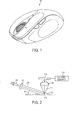
1 zeigt eine Ausführungsform einer optischen Maus 100, und 2 illustriert eine Ausführungsform einer optischen Architektur 200 für die optische Maus 100. Die optische Architektur 200 weist eine Lichtquelle 202 auf, die konfiguriert ist, einen Lichtstrahl 204 in Richtung einer Tracking-Oberfläche 206 zu emittieren, so dass der Lichtstrahl 204 an einer Stelle 210 auf die Oberfläche trifft. Der Lichtstrahl 204 hat eine Auftreffwinkel θ in Bezug zu einer Ebene der Tracking-Oberfläche 206. Die optische Architektur 100 kann ferner eine kollimierende Linse 211 aufweisen, welche zwischen der Lichtquelle 202 und der Tracking-Oberfläche 206 angeordnet ist, um den Lichtstrahl 204 zu kollimieren. Obwohl 1 eine portable Maus darstellt, wird es verstanden werden, dass die dargestellte Architektur in jeder anderen geeigneten Maus verwendet werden kann. 1 shows an embodiment of an optical mouse 100 , and 2 illustrates an embodiment of an optical architecture 200 for the optical mouse 100 , The optical architecture 200 has a light source 202 on which is configured a light beam 204 towards a tracking surface 206 to emit, so that the light beam 204 at one point 210 hits the surface. The light beam 204 has an incident angle θ with respect to a plane of the tracking surface 206 , The optical architecture 100 may further include a collimating lens 211 which is between the light source 202 and the tracking interface 206 is arranged to the light beam 204 to collapse. Even though 1 represents a portable mouse, it will be understood that the illustrated architecture can be used in any other suitable mouse.

Die Lichtquelle 202 ist konfiguriert, um Licht in einem blauen Bereich oder nahe eines blauen Bereiches des sichtbaren Spektrums zu emittieren. Die Ausdrücke ”in einem blauen Bereich oder nahe eines blauen Bereiches des sichtbaren Spektrums” sowie ”blau”, ”Blaulicht”, ”Blaulichtquelle” und ähnliche, wie sie hierin verwendet werden, beschreiben Licht, welches eine oder mehrere Emissionslinien oder -bänder in oder nahe einem blauen Bereich eines sichtbaren Lichtspektrums, zum Beispiel in einem Bereich von 400–490 nm, aufweist. Diese Ausdrücke können ebenso Licht innerhalb des nahen UV bis zum nahen grünen Bereich beschreiben, welches in der Lage ist, die Vorteile eines optischen Aufhellers, der empfindlich auf blaues Licht ist, wie nachstehend in größerem Detail beschrieben, zu aktivieren oder anderweitig zu auszunutzen.The light source 202 is configured to emit light in a blue region or near a blue region of the visible spectrum. The terms "in a blue region or near a blue region of the visible spectrum" and "blue", "blue light", "blue light source" and the like, as used herein, describe light having one or more emission lines or bands in or near a blue region of a visible light spectrum, for example in a range of 400-490 nm. These terms may also describe light within the near UV to near green range that is capable of activating or otherwise exploiting the benefits of an optical brightener that is sensitive to blue light, as described in greater detail below.

In verschiedenen Ausführungsformen kann die Lichtquelle 202 konfiguriert sein um inkohärentes Licht oder kohärentes Licht auszugeben, und kann einen oder mehrere Laser, LEDs, OLEDs (organic light emitting devices), schmalbandige LEDs oder jede andere geeignete Licht emittierende Vorrichtung verwenden. Ferner kann die Lichtquelle 202 konfiguriert sein, um Licht zu emittieren, welches in der Erscheinung blau ist, oder kann konfiguriert sein, um Licht zu emittieren, welches für einen Beobachter eine andere Erscheinung als blau hat. Zum Beispiel können weiße LED Lichtquellen ein blaues LED Plättchen (blue LED die) (aufweisend zum Beispiel InGaN) entweder in Kombination mit LEDs von anderen Farben, oder in Kombination mit einem Szintillator oder Leuchtstoff (phosphor) wie zum Beispiel Cer dotiertes Yttrium-Aluminium-Granat oder in Kombination mit anderen Strukturen verwenden, die andere Wellenlängen von Licht emittieren, um Licht zu produzieren, dass für einen Nutzer weiß erscheint. In noch einer anderen Ausführungsform weist die Lichtquelle 202 eine gewöhnliche Breitband-Lichtquelle in Kombination mit einem Bandpassfilter auf, welcher blaues Licht passieren lässt. Solche Lichtquellen fallen innerhalb die Bedeutung von ”Blaulicht” und ”Blaulichtquelle”, wie sie hierin verwendet werden, aufgrund des Vorhandenseins von blauen Wellenlängen in dem Licht, welches von diesen Strukturen emittiert wird.In various embodiments, the light source 202 be configured to output incoherent or coherent light, and may use one or more lasers, LEDs, organic light emitting devices (OLEDs), narrow band LEDs, or any other suitable light emitting device. Furthermore, the light source 202 be configured to emit light that is blue in appearance, or may be configured to emit light that has an appearance other than blue to an observer. For example, white LED light sources may include a blue LED die (comprising, for example, InGaN) either in combination with LEDs of other colors, or in combination with a scintillator or phosphor such as cerium-doped yttrium-aluminum. Use garnet or in combination with other structures that emit other wavelengths of light to produce light that appears white to a user. In yet another embodiment, the light source 202 an ordinary broadband light source in combination with a bandpass filter that lets blue light pass through. Such light sources fall within the meaning of "blue light" and "blue light source" as used herein due to the presence of blue wavelengths in the light emitted by these structures.

Fortsetzend mit 2, ein gewisser Teil des einfallenden Lichtstrahls 204 wird von der Tracking-Oberfläche 212 reflektiert, wie bei 212 angezeigt, und wird durch eine Linse 214 auf einen Bildsensor 216 abgebildet. Wie in 2 dargestellt, ist die Lichtquelle positioniert, so dass der einfallende Lichtstrahl einen schrägen Winkel relativ zu der Tracking-Oberfläche hat, und der Bildsensor 216 ist positioniert, um eine nicht-spiegelnde Reflexion 206 des einfallenden Lichtstahls 204 zu detektieren. Die Verwendung eines einfallenden Lichtstrahls 204 mit einem schrägen Winkel relativ zu der Tracking-Oberfläche ermöglicht, dass Schatten, die durch die Wechselwirkung von dem einfallenden Lichtstrahl 204 mit Merkmalen der Tracking-Oberfläche gebildet werden, als Tracking-Merkmale detektiert werden. Wie vorstehend beschrieben, kann die Verwendung einer blauen Lichtquelle mit einer schrägen optischen Architektur Vorteile gegenüber der Verwendung von anderen Farben von Licht in einer schrägen optischen Maus bieten, welche Vorteile helfen, die Leistungsfähigkeit auf einer Vielfalt von Tracking-Oberflächen zu verbessern.Continuing with 2 , a certain part of the incoming beam of light 204 gets from the tracking interface 212 reflected, as in 212 displayed, and is through a lens 214 on an image sensor 216 displayed. As in 2 As shown, the light source is positioned so that the incident light beam has an oblique angle relative to the tracking surface, and the image sensor 216 is positioned to provide a non-specular reflection 206 of the incident light beam 204 to detect. The use of an incident light beam 204 At an oblique angle relative to the tracking surface, that shade allows for the interaction of the incident light beam 204 formed with features of the tracking surface, are detected as tracking features. As described above, the use of a blue light source having an oblique optical architecture can provide advantages over the use of other colors of light in an oblique optical mouse, which benefits to improve performance on a variety of tracking surfaces.

Fortsetzend mit 2, der Bildsensor 216 ist konfiguriert um einem Controller 218 Bilddaten zur Verfügung zu stellen. Der Controller 218 ist konfiguriert, um eine Mehrzahl von zeitlich aufeinanderfolgenden Rahmen (frames) von Bilddaten von dem Bildsensor 216 zu erfassen, um die Bilddaten zu prozessieren, um ein oder mehrere Tracking-Merkmale in der Mehrzahl von zeitlich aufeinander folgenden Bildern der Tracking-Oberfläche zu lokalisieren und um Änderungen in der Position/den Positionen von der Mehrzahl von zeitlich aufeinander folgenden Bildern der Tracking-Oberfläche nach zu verfolgen, um die Bewegung der optischen Maus 100 nach zu verfolgen. Das Lokalisieren und das Nachverfolgen von Oberflächenmerkmalen kann auf jede geeignete Art und Weise durchgeführt werden, und wird hierin nicht weiter im Detail beschrieben.Continuing with 2 , the image sensor 216 is configured around a controller 218 To provide image data. The controller 218 is configured to include a plurality of temporally successive frames of image data from the image sensor 216 to capture the image data per to locate one or more tracking features in the plurality of temporally successive images of the tracking surface and to track changes in the position / positions of the plurality of temporally successive images of the tracking surface Movement of the optical mouse 100 to track. The localization and tracking of surface features may be performed in any suitable manner, and will not be described in further detail herein.

Der einfallende Lichtstrahl 204 kann konfiguriert sein, um jeden geeigneten Winkel mit der Tracking-Oberfläche 206 zu haben. Im Allgemeinen ist in einer schrägen Architektur der einfallende Lichtstrahl 204 konfiguriert, um einen relativ flachen Winkel in Bezug zu der Normalen der Tracking-Oberfläche zu haben. Beispiele von geeigneten Winkeln schließen ein, sind aber nicht beschränkt auf, Winkel in einem Bereich von 0 bis 45 Grad relativ zu einer Ebene der Tracking-Oberfläche. Es wird eingesehen werden, dass dieser Bereich von Winkeln dargelegt ist zum Zweck eines Beispiels und dass andere geeignete Winkel außerhalb dieses Bereiches verwendet werden können.The incident light beam 204 Can be configured to any suitable angle with the tracking surface 206 to have. In general, in an oblique architecture, the incident light beam 204 configured to have a relatively shallow angle relative to the normal of the tracking surface. Examples of suitable angles include, but are not limited to, angles in a range of 0 to 45 degrees relative to a plane of the tracking surface. It will be appreciated that this range of angles is set forth for purposes of example and that other suitable angles outside this range may be used.

Der Bildsensor 216 kann konfiguriert sein, um Licht bei jedem geeigneten Winkel relativ zu der Normalen der Tracking-Oberfläche zu detektieren. Im Allgemeinen wird die Intensität des reflektierten Lichts zunehmen, wenn der Bildsensor 216 näher an dem Reflexions-Spiegelwinkel positioniert ist. Für eine Lichtquelle, die einen Strahl bei einem Winkel innerhalb des oben angegebenen Bereichs relativ zu der Ebene der Tracking-Oberfläche emittiert, beinhalten geeignete Detektorwinkel, sind aber nicht beschränkt auf, Winkel von 0 bis +/–10 Grad von der Normalen der Tracking-Oberfläche.The image sensor 216 may be configured to detect light at any suitable angle relative to the normal of the tracking surface. In general, the intensity of the reflected light will increase when the image sensor 216 is positioned closer to the reflection mirror angle. For a light source that emits a beam at an angle within the above specified range relative to the plane of the tracking surface, suitable detector angles include, but are not limited to, angles from 0 to +/- 10 degrees from the normal of the tracking. Surface.

Wie oben dargelegt, kann die Verwendung einer Lichtquelle, die Licht in oder nahe einem blauen Bereich des sichtbaren Spektrums emittiert, unerwartete Vorteile gegenüber roten und infraroten Lichtquellen bieten, die üblicherweise in LED- und Lasermäusen verwendet werden. Diese Vorteile mögen nicht wahrgenommen worden sein aufgrund von anderen Faktoren, die zu der Wahl von roten und infraroten Lichtquellen im Vergleich zu blauen Lichtquellen geführt haben könnten. Zum Beispiel mögen gegenwärtig verfügbare blaue Lichtquellen höherer Raten von Leistungsverbrauch und höher Kosten als gegenwärtig verfügbare rote und infrarote Lichtquellen haben, so dass dies wegführt von der Wahl von blauen Lichtquellen als eine Lichtquelle in einer optischen Maus. Jedoch, wie oben beschrieben, bietet blaues Licht verglichen mit Licht von längeren Wellenlängen vielfältige Vorteile wie zum Beispiel einen besseren Kontrast, eine höher Reflexionsintensität, eine geringere Eindringtiefe, etc.As As outlined above, the use of a light source can be light emitted in or near a blue region of the visible spectrum, unexpected advantages provide red and infrared light sources commonly used in LED and laser mice become. These benefits do not like have been perceived due to other factors contributing to the Choice of red and infrared light sources compared to blue Led light sources could have. For example like currently available blue light sources higher Rates of power consumption and higher costs than currently available red ones and have infrared light sources so that this leads away from the choice of blue light sources as a light source in an optical mouse. However, as described above, blue light provides compared to Light from longer Wavelengths manifold advantages such as a better contrast, a higher reflection intensity, a lower penetration depth, etc.

Die Vorteile, die von blauem Licht, so wie hierin definiert, angeboten werden, entstehen zumindest teilweise aus der Natur der physikalischen Wechselwirkung von blauem Licht mit reflektierenden Oberflächen verglichen mit rotem oder infrarotem Licht. Zum Beispiel hat blaues Licht eine höhere Intensität der Reflexion von dielektrischen Oberflächen als rotes und infrarotes Licht. 3 illustriert die Reflexion eines einfallenden Lichtstrahls 302 von einer dielektrischen Platte 304, die aus einem Material hergestellt ist, das transparent für sichtbares Licht ist, die eine Dicke d hat und die einen Brechungsindex n hat. Wie illustriert, wird ein Teil des einfallenden Lichtstrahls 302 von einer Frontseite 306 der Platte weg reflektiert, und ein Teil des Lichts wird durch das Innere der Platte 304 hindurch transmittiert. Das transmittierte Licht trifft auf die Rückseite 308 der Platte, wo ein Teil des Lichts durch die Rückseite 308 hindurch transmittiert wird und ein Teil zurück reflektiert wird in Richtung zu der Frontseite 306. Licht, welches auf die Frontseite einfällt, wird erneut teilweise reflektiert und teilweise transmittiert und so weiter.The advantages offered by blue light as defined herein arise, at least in part, from the nature of the physical interaction of blue light with reflective surfaces as compared to red or infrared light. For example, blue light has a higher intensity of reflection from dielectric surfaces than red and infrared light. 3 illustrates the reflection of an incident light beam 302 from a dielectric plate 304 made of a material transparent to visible light having a thickness d and having a refractive index n. As illustrated, becomes a part of the incident light beam 302 from a front 306 the plate is reflected away, and part of the light passes through the interior of the plate 304 transmitted through. The transmitted light hits the back 308 the plate, where part of the light through the back 308 is transmitted through and a part is reflected back towards the front 306 , Light incident on the front is again partially reflected and partially transmitted, and so on.

Das Licht in dem Strahl von einfallendem Licht 302 hat eine Vakuum Wellenlänge λ. Der Reflexionskoeffizient oder die Reflexionsamplitude, durch r bezeichnet, und der Transmissionskoeffizient oder die Transmissionsamplitude, durch t bezeichnet, an der Frontseite 306 der Platte 304 sind wie folgt: r = (1 – n) / (1 + n) t = 2 / (1 + n) The light in the beam of incident light 302 has a vacuum wavelength λ. The reflection coefficient or the reflection amplitude, denoted by r, and the transmission coefficient or the transmission amplitude, denoted by t, at the front side 306 the plate 304 are as follows: r = (1-n) / (1 + n) t = 2 / (1 + n)

An der Rückseite 308 der Platte sind der entsprechende Reflexionskoeffizient, durch r' bezeichnet, und der Transmissionskoeffizient, durch t' bezeichnet, wie folgt: r' = (1 – n) / (1 + n) t' = 2n / (1 + n) At the back 308 the plate is the corresponding reflection coefficient, denoted by r ', and the transmission coefficient, denoted by t', as follows: r '= (1-n) / (1 + n) t '= 2n / (1 + n)

Es wird angemerkt, dass die Reflexionskoeffizienten und Transmissionskoeffizienten oder Amplituden nur von dem Brechungsindex der Platte 304 abhängen. Wenn der einfallende Lichtstrahl auf die Oberfläche unter einem Winkel mit Bezug zu der Normalen trifft, sind gemäß den Fresnel Gleichungen die Amplitudengleichungen ebenso Funktionen des Winkels.It is noted that the reflection coefficients and transmission coefficients or amplitudes only depend on the refractive index of the plate 304 depend. When the incident light beam strikes the surface at an angle with respect to the normal, according to the Fresnel equations, the amplitude equations are also functions of the angle.

Eine Phasenverschiebung φ, die durch den Brechungsindex der Platte 304 bewirkt wird, der unterschiedlich ist von der Luft, welche die Platte 304 umgibt, ist wie folgt gegeben: φ = 2πnd / λ A phase shift φ caused by the refractive index of the plate 304 is effected, which is different from the air, which the plate 304 surrounds, is given as follows: φ = 2πnd / λ

Eine Berücksichtigung der Transmissionsphasenverschiebung und ein Summieren der Amplituden von allen partiellen Reflexionen und Transmissionen ergeben die folgenden Ausdrücke für die insgesamten Reflexions- und Transmissionskoeffizienten oder Amplituden der Platte:

Figure 00090001
A consideration of the transmissions phase shifting and summing the amplitudes of all the partial reflections and transmissions gives the following expressions for the total reflection and transmission coefficients or amplitudes of the disk:
Figure 00090001

Bei dem Grenzfall einer geringen Plattendicke d reduziert sich die Gleichung der reflektierten Amplitude auf eine einfachere Form:

Figure 00090002
In the limiting case of a small plate thickness d, the equation of the reflected amplitude reduces to a simpler form:
Figure 00090002

Bei diesem Grenzfall führt das reflektierte Licht das einfallende Lichtfeld um 90 Grad in der Phase an und seine Amplitude ist proportional sowohl zu 1/λ und zu dem dielektrischen Polarisationskoeffizient (n2 – 1). Die 1/λ Abhängigkeit der Streuamplitude repräsentiert, dass die Intensität des von einer dünnen dielektrischen Platte reflektierten Lichts proportional zu dem Quadrat der Amplitude ist. Daher ist die Intensität der reflektierten Lichts größer für kürzere Wellenlängen als für längere Wellenlängen von Licht.In this limiting case, the reflected light introduces the incident light field 90 degrees in phase and its amplitude is proportional to both 1 / λ and the dielectric polarization coefficient (n 2 -1). The 1 / λ dependence of the scattering amplitude represents that the intensity of the light reflected from a thin dielectric plate is proportional to the square of the amplitude. Therefore, the intensity of the reflected light is greater for shorter wavelengths than for longer wavelengths of light.

Von dem Standpunkt einer optischen Maus, unter Bezugnahme auf 4, und wie oben mit Bezug auf 3 beschrieben, kann die Tracking-Oberfläche modelliert werden als aufweisend eine große Anzahl von reflektierenden Elementen in der Form einer dielektrischen Platte, wobei jede entsprechend der lokalen Höhe und der Steigung der Oberfläche orientiert ist. Jede von diesen dielektrischen Platten reflektiert einfallendes Licht; manchmal befindet sich das reflektierte Licht innerhalb der numerischen Apertur der abbildenden Linse und ist daher durch die Linse gefangen, und andere Male wird das Licht nicht von der Linse gefangen, was zu einen dunklen Tracking-Merkmal an dem Detektor führt. Ein Betrieb in Blau bei 470 nm führt zu einer Erhöhung der Intensität des reflektierten Lichts in den hellen Merkmalen um ein Maß 8502/4702 ≈ 3,3 im Vergleich zu infrarotem Licht, welches eine Wellenlänge von 850 nm hat, und einen Faktor von 6302/4702 ≈ 1,8 im Vergleich zu rotem Licht, welches eine Wellenlänge von 630 nm hat. Dies führt zu einer Kontrastverbesserung in den Blaulichtbildern an dem Detektor, weil helle Merkmale auf dem Detektor heller sind als sie in korrespondierenden roten oder infraroten Bildern erscheinen. Diese Bilder mit höherem Kontrast erlauben die akzeptable Identifikation und ein robusteres Nachverfolgen von Tracking-Merkmalen mit geringeren Lichtquellenintensitäten, und können daher die Leistungsfähigkeit der Nachverfolgung (tracking performance) im Vergleich zu infraroten oder roten Lichtmäusen auf einer Vielfalt von Oberflächen verbessern, wobei ebenso der Leistungsverbrauch reduziert und eine Batterielebenddauer erhöht wird.From the standpoint of an optical mouse, with reference to 4 , and as above with respect to 3 As described, the tracking surface may be modeled as having a large number of reflective elements in the form of a dielectric plate, each oriented according to the local height and the slope of the surface. Each of these dielectric plates reflects incident light; sometimes the reflected light is within the numerical aperture of the imaging lens and is therefore trapped by the lens, and at other times the light is not captured by the lens, resulting in a dark tracking feature on the detector. An operation in blue at 470 nm leads to an increase in the intensity of reflected light in the bright features by an amount 850 2/470 2 ≈ 3.3 in comparison to infrared light having a wavelength of 850 nm, and a factor of 630 2/470 2 ≈ 1.8 in comparison to a red light having a wavelength of 630 nm. This results in a contrast enhancement in the blue light images at the detector because bright features on the detector are brighter than they appear in corresponding red or infrared images. These higher contrast images allow acceptable identification and robust tracking of tracking features with lower light source intensities, and thus can improve tracking performance over infrared or red light mice on a variety of surfaces, as well as power consumption reduced and a battery life is increased.

5 illustriert einen anderen Vorteil der Verwendung von blauem Licht im Vergleich zu rotem oder infraroten Licht in einer optischen Maus, insofern die Eindringtiefe von blauem Licht geringer ist geringer als die von rotem oder infrarotem Licht. Im Allgemeinen dringt das elektrische Feld der Strahlung, die auf eine Oberfläche trifft, in die Oberfläche zu einem gewissen Maß ein. 5 zeigt eine einfache Illustrierung der Amplitude eines elektrischen Feldes innerhalb einer metallischen Platte als Funktion der Tiefe. Wie illustriert, fällt das elektrische Feld des einfallenden Lichtstrahls exponentiell innerhalb des Metalls mit einem charakteristischen e-fachen Abstand ab, der proportional zu der Wellenlänge ist. Unter Berücksichtigung der Wellenlängenabhängigkeit kann sich infrarotes Licht um einen Faktor 1,8 weiter in ein metallisches Material erstrecken als blaues Licht. Kurze Eindringtiefen treten ebenso auf, wenn blaues Licht genauso auf nicht-metallische, dielektrische Oberflächen auftrifft; die exakte Eindringtiefe hängt von den Materialeingenschaften ab. 5 illustrates another advantage of using blue light compared to red or infrared light in an optical mouse in that the depth of penetration of blue light is less than that of red or infrared light. In general, the electric field of the radiation striking a surface penetrates into the surface to some extent. 5 shows a simple illustration of the amplitude of an electric field within a metallic plate as a function of depth. As illustrated, the electric field of the incident light beam exponentially drops within the metal at a characteristic e-fold distance that is proportional to the wavelength. Taking into account the wavelength dependence, infrared light can extend further by a factor of 1.8 into a metallic material than blue light. Short penetration depths also occur when blue light impinges equally on non-metallic dielectric surfaces; the exact penetration depth depends on the material properties.

Die geringere Eindringtiefe von blauem Licht verglichen mit rotem oder infraroten Licht kann von dem Standpunkt von optischen Navigationsanwendungen aus verschiedenen Gründen vorteilhaft sein. Zunächst können die Bildkorrelierungsverfahren, die von dem Controller verwendet werden um Tracking-Merkmalen zu folgen, Bilder erfordern, die sich in einer eins zu eins Übereinstimmung mit der darunter liegenden Navigationsoberfläche befinden. Licht, welches von verschiedenen Tiefen innerhalb der Oberfläche reflektiert wird, kann die Korrelationsberechnung durcheinander bringen. Ferner führt Licht, welches in das Material abzweigt (leak), dazu, dass weniger Licht den Bilddetektor erreicht.The lower penetration depth of blue light compared to red or Infrared light may be from the standpoint of optical navigation applications for various reasons be beneficial. First can the image correlation method used by the controller In order to follow tracking features, pictures will be required that are in a one to one match with the underlying navigation surface. Light, which can be reflected from different depths within the surface mess up the correlation calculation. Furthermore, light, which leads into the material (leak), causing less light to enter the image detector reached.

Zusätzlich ist die geringere Eindringtiefe wünschenswert weil sie zu einem geringeren Übersprechen zwischen angrenzenden und fast benachbarten Pixeln und einer höheren Modulationstransferfunktion (modulation transfer function – MTF) an dem Bildsensor führen kann. Um diese Effekte zu verstehen betrachte man den Unterschied zwischen einem infraroten Photon mit langer Wellenlänge und einem blauen Photon mit kurzer Wellenlänge, die auf einen Silizium CMOS Detektor treffen. Die Absorption eines Photons in einem Halbleiter ist abhängig von der Wellenlänge. Die Absorption ist stark für kurzwelliges Licht, nimmt aber ab für lange Wellenlängen sowie die Bandlückenenergie angenähert wird. Bei einer geringen Absorption laufen langwellige Photonen weiter innerhalb des Halbleiters, und die entsprechende elektrische Ladung, die innerhalb des Materials erzeugt wird, muss, um gesammelt zu werden, weiter laufen als die entsprechende Ladung, die von einem kurzwelligen blauen Photon erzeugt wurde. Mit der größeren Laufstrecke können Ladungsträger von dem langwelligen Licht diffundieren und sich innerhalb des Materials mehr ausbreiten als die (Ladungsträger von den) blauen Photonen. Daher kann die Ladung, die innerhalb eines Pixels erzeugt wurde, ein Täuschungssignal in einem benachbarten Pixel herbeiführen, was zu einem Übersprechen und zu einer MFT Reduzierung in dem elektro-optischen System führt.In addition, the lower penetration depth is desirable because it can result in less crosstalk between adjacent and near-adjacent pixels and a higher modulation transfer function (MTF) on the image sensor. To understand these effects, consider the difference between a long wavelength infrared photon and a short wavelength blue photon striking a silicon CMOS detector. The absorption of a photon in a semiconductor depends on the wavelength. The absorption is strong for short-wave light, but decreases for long wavelengths as well as the bandgap energy is approximated. At low absorption, long wavelength photons continue to travel within the semiconductor, and the corresponding electrical charge generated within the material must travel further than the corresponding charge generated by a short wavelength blue photon to be collected. With the larger running distance charge carriers can diffuse from the long-wave light and spread within the material more than the (charge carriers of the) blue photons. Therefore, the charge generated within a pixel may induce a deception signal in an adjacent pixel, resulting in crosstalk and MFT reduction in the electro-optic system.

Als noch ein anderer Vorteil für die Verwendung von blauem Licht verglichen mit anderen Lichtquellen ist blaues Licht fähig kleinere Tracking-Merkmale aufzulösen als infrarotes oder rotes Licht. Im Allgemeinen ist das kleinste Merkmal, welches ein optisches bildgebendes System auflösen kann, durch Beugung begrenzt. Das Kriterium von Rayleigh gibt an, dass die Größe d eines Oberflächen-Merkmals, welches von einem angrenzenden Objekt der gleichen Größe unterschieden werden kann, durch die Beziehung
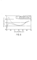
 d ≥ λ / NA gegeben ist, wobei λ die Wellenlänge des einfallenden Lichts und NA die numerische Apertur des bildgebenden Systems ist. Die Proportionalität zwischen d und λ zeigt an, dass mit blauem Licht kleinere Oberflächen-Merkmale auflösbar sind als mit Licht von längeren Wellenlängen. Zum Beispiel kann eine blaue Maus, die bei λ = 470 nm mit f/1 Optiken betrieben wird, Merkmale herunter bis zu einer Größe von ungefähr bei 2λ ≈ 940 nm abbilden. Für einen infraroten VCSEL (vertical-cavity surface-emitting laser), der bei 850 nm betrieben wird, vergrößert sich die minimale Merkmalsgröße, die abgebildet werden kann, auf 1,7 μm (1,7 Mikrometer). Deshalb mag die Verwendung von blauem Licht erlauben, dass kleinere Tracking-Merkmale mit geeigneten Bildsensoren und optischen Komponenten abgebildet werden.As yet another advantage to the use of blue light compared to other light sources, blue light is capable of resolving smaller tracking features than infrared or red light. In general, the smallest feature that an optical imaging system can resolve is limited by diffraction. Rayleigh's criterion indicates that the size d of a surface feature that can be distinguished from an adjacent object of the same size is represented by the relationship d ≥ λ / NA where λ is the wavelength of the incident light and NA is the numerical aperture of the imaging system. The proportionality between d and λ indicates that with blue light, smaller surface features are resolvable than with light of longer wavelengths. For example, a blue mouse operated at λ = 470 nm with f / 1 optics can map features down to a size of approximately at 2λ≈940 nm. For an infrared vertical cavity surface-emitting laser operating at 850 nm, the minimum feature size that can be imaged increases to 1.7 μm (1.7 microns). Therefore, the use of blue light may allow smaller tracking features to be imaged with suitable image sensors and optical components.

Blaues Licht mag ebenso ein höheres Reflexionsvermögen haben als andere Wellenlängen von Licht auf verschiedenartigen spezifischen Oberflächen. Zum Beispiel zeigt 6 einen Graph des Reflexionsvermögens von weißem Papier mit und ohne optischen Aufheller über das sichtbare Spektrum. Ein ”optischer Aufheller” ist ein fluoreszierender Farbstoff, der zu vielen Arten von Papier hinzugefügt ist, um das Papier weiß und ”sauber” erscheinen zu lassen. 6 zeigt, dass weißes Papier mit einem optischen Aufheller in und nahe einem blauen Bereich eines sichtbaren Lichtspektrums vergleichsweise mehr reflektiert als in einigen anderen Bereichen des Spektrums. Deshalb kann die Verwendung von Licht in oder nahe einem blauen Bereich eines sichtbaren Spektrums als Mauslichtquelle zu synergistischen Effekten führen, wenn sie auf Oberflächen verwendet wird, die optische Aufheller enthalten, genauso wie (auf) anderen wie fluoreszierende oder reflexionsverbesserte Tracking-Oberflächen, wodurch die Maus Performance auf solchen Oberflächen in einem sogar größeren Ausmaß verbessert wird als auf anderen Oberflächen.Blue light may also have a higher reflectance than other wavelengths of light on various specific surfaces. For example, shows 6 a graph of the reflectivity of white paper with and without optical brightener over the visible spectrum. An "optical brightener" is a fluorescent dye that is added to many types of paper to make the paper appear white and "clean". 6 shows that white paper with an optical brightener in and near a blue region of a visible light spectrum reflects comparatively more than in some other regions of the spectrum. Therefore, the use of light in or near a blue region of a visible spectrum as a mouse light source can produce synergistic effects when used on surfaces containing optical brighteners, as well as other such as fluorescent or reflection enhanced tracking surfaces, thereby reducing the surface area Mouse performance on such surfaces is improved to an even greater extent than on other surfaces.

Solche Effekte können Vorteile in verschiedenartigen Benutzungsszenarios bieten. Zum Beispiel ist eine übliche Nutzerumgebung für eine portable Maus ein Konferenzraum. Viele Konferenzraumtische sind aus Glas hergestellt, was im Allgemeinen eine schlechte Oberfläche für die Perfomance einer optischen Maus ist. Um die Maus-Perfomance auf transparenten Oberflächen wie zum Beispiel Glas zu verbessern, können Nutzer ein Blatt Papier über der transparenten Oberfläche zur Verwendung als provisorisches Mauspad platzieren. Deshalb können, wenn das Papier einen optischen Aufheller aufweist, synergistische Effekte in der Performance der Maus verglichen zu der Nutzung von anderen Oberflächen erreicht werden, was einen reduzierten Stromverbrauch und damit eine bessere Batterielebensdauer für eine batteriebetriebene Maus ermöglicht.Such Effects can To provide benefits in a variety of usage scenarios. For example is a common one User environment for a portable mouse a conference room. Many conference room tables are made of glass, which is generally a poor surface for the performance an optical mouse. To the mouse performance on transparent surfaces For example, to enhance glass, users can place a piece of paper over the transparent one surface for use as a temporary mouse pad. Therefore, if the paper has an optical brightener, synergistic effects in the performance of the mouse compared to the use of others Reached surfaces which results in a reduced power consumption and thus a better one Battery life for a battery powered mouse allows.

Ähnliche synergistische Effekte in der Performance können erreicht werden durch ein Behandeln oder ein Vorbereiten von anderen Oberflächen um helligkeitsverstärkende Eigenschaften zu haben, so wie eine größere Reflektivität, fluoreszierende oder phosphoreszierende Emission etc., wenn (die Oberfläche) Licht in oder nahe einem blauen Bereich des sichtbaren Spektrums ausgesetzt ist. Zum Beispiel können ein Mauspad oder andere zweckbestimmte Oberflächen zur Verwendung von Maus-Tracking einen Helligkeitsverstärker wie zum Beispiel ein Material mit hoher Reflektivität in dem blauen Bereich aufweisen und/oder ein Material, das einfallendes Licht absorbiert und im blauen Bereich fluoresziert oder phosphoresziert. Wenn mit einer Blaulichtmaus verwendet kann solch ein Material einen größeren Kontrast liefern als Oberflächen ohne eine solche reflektierende oder fluoreszierende Oberfläche und kann dadurch zu einer guten Nachverfolgungsperformance, zu einem geringen Stromverbrauch etc. führen.Similar synergistic effects in the performance can be achieved by treating or preparing other surfaces for brightness enhancing properties to have, as a greater reflectivity, fluorescent or phosphorescent emission, etc., when (the surface) light exposed in or near a blue region of the visible spectrum is. For example, you can a mouse pad or other dedicated surface for using mouse tracking a brightness amplifier such as a material with high reflectivity in the have blue area and / or a material that is incidental Absorbed light and fluorescent or phosphorescent in the blue region. When used with a blue light mouse, such a material can make one greater contrast deliver as surfaces without such a reflective or fluorescent surface and This can lead to a good follow-up performance, to a Low power consumption, etc. lead.

Im dem Fall einer schrägen Lasermaus, kann die Verwendung von blauem kohärenten Licht im Vergleich zu der Verwendung von rotem oder infrarotem kohärenten Licht Vorteile betreffend die Specklegröße bieten. Weil die Specklegröße proportional zu der Wellenlänge ist, erzeugt blaues kohärentes Licht kleinere Speckle als entweder eine rote oder infrarote Laserlichtquelle. In einigen Ausführungsformen von Lasermäusen ist es wünschenswert die am kleinsten möglichen Speckle zu haben, da Speckle eine schädliche Rauschquelle sein können und die Tracking-Performance verschlechtern können. Ein blauer Laser hat eine relativ kleine Specklegröße und daher werden mehr blaue Speckle die Fläche eines gegebenen Pixels besetzen als mit einem roten oder einem infraroten Laser. Dies kann ein Ausmitteln des Speckle-Rauschens in dem Bildern erleichtern, was zu einem besseren Nachverfolgen führt.In the case of an oblique laser mouse, the use of blue coherent light in the ver similar to the use of red or infrared coherent light, offer advantages regarding speckle size. Because the speckle size is proportional to the wavelength, blue coherent light produces smaller speckles than either a red or infrared laser light source. In some embodiments of laser mice, it is desirable to have the smallest possible speckle, as speckles can be a detrimental noise source and can degrade tracking performance. A blue laser has a relatively small speckle size and therefore more blue speckles will occupy the area of a given pixel than with a red or an infrared laser. This can facilitate averaging out the speckle noise in the image, resulting in better tracking.
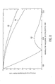
Die Vorteile des Verwendens einer blauen Lichtquelle mögen nicht vollständig realisiert werden durch eine einfache Konversion oder durch ein Nachrüsten einer Rotlichtmaus mit einer blauen Lichtquelle. Zum Beispiel zeigt 7 eine graphische Darstellung des Brechungsindex von einem beispielhaften Linsenmaterial (Polykarbonat) als eine Funktion der Wellenlänge. Aus dieser Figur ist ersichtlich, dass der Brechungsindex indirekt proportional zu der Wellenlänge des Lichts ist. Deshalb ist der Brechungsindex für blaues Licht größer als für rotes Licht. Die Brechungsindizes von anderen Materialien als Polykarbonat können mit der Wellenlänge zu einem unterschiedlichen Ausmaß als Polykarbonat variieren, haben aber eine ähnliche indirekte Proportionalität. Als ein Ergebnis dieser Eigenschaft wird ein Blaulichtbild durch eine Linse an einem unterschiedlichen Punkt scharfgestellt als ein Rotlichtbild. Deshalb kann abhängig von optischen Systemparametern wie zum Beispiel der Tiefenschärfe (depth of focus) eine solche Differenz eine substantielle Bildunschärfe verursachen und kann deshalb zu einer schlechten Bewegungsnachverfolgung (motion tracking) führen.The benefits of using a blue light source may not be fully realized by a simple conversion or by retrofitting a red light mouse with a blue light source. For example, shows 7 a plot of the refractive index of an exemplary lens material (polycarbonate) as a function of wavelength. It can be seen from this figure that the refractive index is indirectly proportional to the wavelength of the light. Therefore, the refractive index is greater for blue light than for red light. The refractive indices of materials other than polycarbonate may vary with wavelength to a different extent than polycarbonate, but have a similar indirect proportionality. As a result of this characteristic, a blue-light image is focused by a lens at a different point than a red-light image. Therefore, depending on optical system parameters such as depth of focus, such a difference can cause substantial image blurring, and therefore may result in poor motion tracking.

Andere nachteilige Effekte können gleichermaßen aus dieser Eigenschaft von Licht entstehen. Zum Beispiel kann ein Bildkontrast verschlechtert werden durch die Verwendung einer blauen Lichtquelle in einer Maus, die für rotes Licht konfiguriert ist. 8 zeigt einen Vergleich von der Modulationstransferfunktion für einoptisches System, welches für die Verwendung mit rotem Licht einer Wellenlänge von 630 nm optimiert ist, bei der optimalen Lichtquellenwellenlänge 800 und ebenso unter zwei unterschiedlichen Nachrüstszenarios für Blaulichtquellen. Zunächst zeigt 8 bei 802 die Modulationstransferfunktion für das Rotlicht optische System, welches mit blauem Licht, das eine Wellenlänge von 470 nm hat, und ohne weitere Anpassungen verwendet wird. Als nächstes zeigt 8 bei 804 die Modulationstransferfunktion für das Rotlicht optische System, welches mit 470 nm blauem Licht verwendet wird und wobei das System angepasst worden ist, so dass ein Blaulichtbild statt ein Rotlichtbild auf dem Bildsensor scharf abgebildet wird. Wie dargestellt ist die Modulationstransferfunktion wesentlich kleiner für die einfache Substitution einer Blaulichtquelle in ein Rotlicht optisches System verglichen mit der Verwendung von rotem Licht, um nähert sich Null an bei verschiedenen räumlichen Frequenzen. Als Ergebnis wird viel Kontrast verloren, wenn ein blaues Licht in eine Rotlichtmaus substituiert wird. Das kann zu einer unakzeptablen Verschlechterung der Performance führen. Ebenso kann sogar die Anpassung des optischen Systems, um das Blaulichtbild auf dem Bildsensor einer Rotlicht optischen Maus scharf abzubilden, zu einem reduzierten Kontrast führen, wie bei 804 gezeigt.Other adverse effects can equally arise from this property of light. For example, image contrast may be degraded by the use of a blue light source in a mouse configured for red light. 8th FIG. 10 shows a comparison of the modulation transfer function for an optical system optimized for use with 630 nm wavelength red light at the optimum light source wavelength 800 and also under two different retrofit scenarios for blue light sources. First shows 8th at 802 the modulation transfer function for the red light optical system which is used with blue light having a wavelength of 470 nm and without further adjustments. Next shows 8th at 804 the modulation transfer function for the red light optical system used with 470 nm blue light, and wherein the system has been adjusted so that a blue light image is sharply imaged on the image sensor rather than a red light image. As shown, the modulation transfer function is significantly smaller for the simple substitution of a blue light source into a red light optical system compared to the use of red light, approaching zero at different spatial frequencies. As a result, much contrast is lost when a blue light is substituted into a red light mouse. This can lead to unacceptable performance degradation. Likewise, even adjusting the optical system to sharply image the blue light image on the image sensor of a red light optical mouse may result in reduced contrast, as in FIG 804 shown.

Andere Eigenschaften außer dem Kontrast können betroffen sein durch das Nachrüsten des Rotlicht optischen Systems mit einer Blaulichtmaus. Zum Beispiel kann solch eine Nachrüstung die Vergrößerung eines auf dem Bildsensor scharf abgebildeten Bildes verändern und kann ebenso optische Aberrationen einführen. Die Vergrößerung beeinträchtigt die Performance in einer optischen Maus, da sie eine Auflösung (Dots pro Inch) und die maximale Geschwindigkeit und Beschleunigung bestimmt, die durch die Maus verfolgbar ist. Diese Konzepte sind qualitativ in den 9 bis 11 illustriert. Zuerst zeigt 9 das scharfe Abbilden eines Bildes von einer Tracking-Oberfläche 902 (die sich in der Objektebene befindet) auf einen Bildsensor 904 (der sich in der Bildebene befindet) in einem Rotlicht optischen System, welches rotes Licht verwendet, das eine Wellenlänge von 630 nm und eine bi-konvexe Linse 906 hat, die konfiguriert ist, um ein Bild auf dem Bildsensor zu verkleinern und scharf abzubilden. Der Abstand von der Tracking-Oberfläche zu einer ersten Oberfläche 908 der Linse beträgt 10,6 mm, und der Abstand von einer zweiten Linsenoberfläche 910 zu dem Bildsensor beträgt 6,6 mm. Ferner beträgt der Radius der Krümmung der ersten Linsenoberfläche 4,0 mm, und der Radius der Krümmung der zweiten Linsenoberfläche beträgt –6,0 mm. Die Bildvergrößerung beträgt –0,6 (–6,6 mm/10,6 mm). Wie illustriert, reproduziert die Verwendung von rotem Licht mit dem Rotlicht optimierten optischen System treu das ”F” Bild auf der Bildebene bei einer gewünschten Vergrößerung. Es wird anerkannt werden, dass die bi-konvexe Linse 906 eine oder mehrere tatsächlich Linse, genauso gut wie andere optische Elemente repräsentieren kann, die in dem Linsensystem enthalten sind.Other features besides contrast may be affected by retrofitting the red light optical system with a blue light mouse. For example, such retrofitting may alter the magnification of an image sharply imaged on the image sensor and may also introduce optical aberrations. The magnification affects the performance in an optical mouse because it determines a resolution (dots per inch) and the maximum speed and acceleration that can be tracked by the mouse. These concepts are qualitative in the 9 to 11 illustrated. First shows 9 the sharp imaging of an image from a tracking surface 902 (which is in the object plane) on an image sensor 904 (which is in the image plane) in a red light optical system using red light having a wavelength of 630 nm and a bi-convex lens 906 configured to reduce and sharply image an image on the image sensor. The distance from the tracking surface to a first surface 908 the lens is 10.6 mm, and the distance from a second lens surface 910 to the image sensor is 6.6 mm. Further, the radius of curvature of the first lens surface is 4.0 mm, and the radius of curvature of the second lens surface is -6.0 mm. The image magnification is -0.6 (-6.6 mm / 10.6 mm). As illustrated, the use of red light with the red-light optimized optical system faithfully reproduces the "F" image on the image plane at a desired magnification. It will be appreciated that the bi-convex lens 906 one or more actually lens, as well as other optical elements that are included in the lens system.

Als nächstes zeigt 10 das gleiche optische System, welches mit blauem Licht, das eine Wellenlänge von 470 nm hat, beleuchtet wird. Wie gesehen werden kann, ist das Bild aufgrund des höheren Brechungsindexes bei dieser Wellenlänge nicht auf dem Bildsensor 904 scharf abgebildet. Dies verursacht, dass das ”F” als ein verschwommener Spot auf dem Bildsensor 904 erscheint, was zu einer schlechten Bewegungsverfolgung durch die Maus führen kann.Next shows 10 the same optical system illuminated with blue light having a wavelength of 470 nm. As can be seen, due to the higher refractive index at this wavelength, the image is not on the image sensor 904 sharply depicted. This causes the "F" as a blurry spot on the image sensor 904 appears, what a poor motion tracking by the mouse.

11 zeigt das gleiche optische System, welches mit 470 nm blauem Licht beleuchtet ist, wobei aber der Bildsensor 906 auf einen Abstand von 6,1 mm von der zweiten Linsenoberfläche 910 verschoben worden ist, um das Blaulichtbild scharf auf dem Bildsensor abzubilden. Obwohl das zu einem scharfen Bild führt, hat sich die Vergrößerung der Maus um ungefähr 8% auf 0,58 verkleinert (–6,1 mm/10,6 mm). Dies führt zu einer Reduzierung der Auflösung (dpi oder Dots pro Inch) der Maus und potentiell zu einer verschlechterten Tracking-Performance. 11 shows the same optical system which is illuminated with 470 nm blue light, but the image sensor 906 at a distance of 6.1 mm from the second lens surface 910 has been moved to image the blue light image sharply on the image sensor. Although this results in a sharp image, the magnification of the mouse has decreased by about 8% to 0.58 (-6.1 mm / 10.6 mm). This leads to a reduction of the resolution (dpi or dots per inch) of the mouse and potentially to a deteriorated tracking performance.

Als nächstes zeigt 12 ein optisches System, welche konfiguriert ist, um ein Blaulichtbild auf einem Bildsensor scharf abzubilden. Verglichen mit dem in den 9 bis 10 gezeigten Rotlicht optischen System, sind die Radien der Krümmung der bi-konvexen Linse sowie der Abstand von dem Bildsensor zu der zweiten Linsenoberfläche für 470 nm Licht optimiert, um die gleiche Vergrößerung und Gesamtlänge zu erhalten wie das Rotlicht optische System. Wie dargestellt, beträgt der Abstand von der Tracking-Oberfläche 1202 (Objektebene) zu der Oberfläche der ersten Linse 1204 10,5 mm, und der Abstand von der zweiten Linsenoberfläche 1206 zu der Bildebene 1208 beträgt 6,7 mm. Ferner sind die Radien der Krümmung der ersten und zweiten Linsenoberflächen 4,3 mm bzw. 6,1 mm. Mit diesen Grundmaßen werden die gleiche Vergrößerung und Gesamtlänge beibehalten verglichen mit dem oben in 9 dargestellten Rotlicht optischen System, obwohl ein scharfes Blaulichtbild auf dem Bilddetektor 1208 abgebildet wird.Next shows 12 an optical system configured to sharply image a blue light image on an image sensor. Compared with that in the 9 to 10 shown red light optical system, the radii of curvature of the bi-convex lens and the distance from the image sensor to the second lens surface for 470 nm light are optimized to obtain the same magnification and overall length as the red light optical system. As shown, the distance from the tracking surface is 1202 (Object plane) to the surface of the first lens 1204 10.5 mm, and the distance from the second lens surface 1206 to the picture plane 1208 is 6.7 mm. Further, the radii of curvature of the first and second lens surfaces are 4.3 mm and 6.1 mm, respectively. With these basic dimensions, the same magnification and overall length are retained as compared to the one above 9 illustrated red light optical system, though a sharp blue light image on the image detector 1208 is shown.

Wie in diesen Figuren illustriert, bewahrt ein bloßes Ändern der Position des Bildsensors zu der Blaulicht Bildebene nicht die Vergrößerung, den Kontrast und andere Bildeigenschaften eines Rotlicht optischen Systems, wenn es mit einem blauen Licht benutzt wird. Stattdessen beeinflussen die Linsenformen und die Abstände zwischen verschiedenen optischen Elementen ebenso gewünschte Performance Charakteristiken. Es wird anerkannt werden, dass die spezifischen Dimensionen und Abstände, die in den 9 bis 12 gezeigt sind, zum Zweck eines Beispiels gezeigt sind und dass ein Blaulicht optisches System jede geeignete Konfiguration, die anders ist als die gezeigte, haben kann.As illustrated in these figures, merely changing the position of the image sensor to the blue light image plane does not preserve the magnification, contrast and other image characteristics of a red light optical system when used with a blue light. Instead, the lens shapes and spacings between different optical elements also affect desired performance characteristics. It will be recognized that the specific dimensions and distances used in the 9 to 12 are shown for purposes of example and that a blue light optical system may have any suitable configuration other than that shown.

In Anbetracht der oben beschriebenen physikalischen Eigenschaften kann die Verwendung von blauem Licht verschiedene Vorteile gegenüber der Verwendung von rotem oder infrarotem Licht in einer optischen Maus bieten. Zum Beispiel kann die höhere Reflektivität und die geringere Eindringtiefe von blauem Licht verglichen mit rotem oder infrarotem Licht die Verwendung einer Lichtquelle mit geringerer Intensität ermöglichen, wodurch möglicherweise die Batterielebensdauer erhöht wird. Dies kann insbesondere vorteilhaft sein, wenn eine Maus auf einem weißen Papier mit einem hinzugefügten Helligkeitsverstärker betrieben wird, da die Intensität einer Fluoreszenz des Helligkeitsverstärkers in dem blauen Bereich des sichtbaren Spektrums stark sein kann. Außerdem mögen die kürzere Kohärenzlänge und kleinere Beugungsgrenzen von blauem Licht verglichen mit rotem Licht von einer optisch äquivalenten (d. h. Linsen, f-Zahl, Bildsensor, etc.) Lichtquelle sowohl längere Bildmerkmal-Korrelationslängen und feinere aufzulösende Oberflächen-Merkmale erlauben, und mögen deshalb einer Blaulicht Maus ermöglichen, auf einer größeren Vielfalt von Oberflächen verwendet zu werden. Beispiele von Oberflächen, die als Tracking-Oberflächen für eine blaue optische Maus verwendet werden können, beinhalten, sind aber nicht beschränkt auf, Papieroberflächen, Textiloberflächen, Keramik, Marmor, Holz, Metall, Granit, Kacheln (tile), Edelstahl, und Teppiche einschließlich Berber und tiefe grobe Wolle (deep shag).In Considering the physical properties described above The use of blue light has several advantages over use of red or infrared light in an optical mouse. For example, the higher reflectivity and the lower penetration of blue light compared to red or infrared light using a light source lower intensity enable, possibly the battery life increases becomes. This can be particularly beneficial when using a mouse a white one Paper with an added one brightness amplifier is operated as the intensity a fluorescence of the brightness amplifier in the blue area of the visible spectrum can be strong. Also like the shorter coherence length and smaller diffraction limits of blue light compared to red light of an optically equivalent (i.e. H. Lenses, f-number, image sensor, etc.) light source both longer image feature correlation lengths and finer be resolved Surface features allow, and like therefore allow a blue light mouse, on a bigger variety used by surfaces to become. Examples of surfaces, as tracking surfaces for one Blue Optical Mouse can be used, but are included not limited on, paper surfaces, Textile surfaces, Ceramic, marble, wood, metal, granite, tile, stainless steel, and carpets including Berber and deep coarse wool (deep shag).

Ferner kann in einigen Ausführungsformen ein Bildsensor, wie zum Beispiel ein CMOS Sensor, der speziell konfiguriert ist, um eine hohe Sensitivität (d. h. Quantenausbeute) in dem blauen Bereich des sichtbaren Spektrums zu haben, in Kombination mit einer Blaulichtquelle verwendet werden. Dies mag sogar die Verwendung von Lichtquellen mit geringerer Leistung ermöglichen und kann deshalb helfen die Lebensdauer der Batterie weiter zu erhöhen.Further may be in some embodiments Image sensor, such as a CMOS sensor, specially configured is to have a high sensitivity (i.e. H. Quantum yield) in the blue region of the visible spectrum to be used in combination with a blue light source. This may even be the use of lower power light sources enable and therefore can help to further increase the life of the battery.

Fortsetzend mit den Figuren zeigt 13 ein Flussdiagramm, welches eine Ausführungsform eines Verfahrens 1300 zum Verfolgen einer Bewegung einer optischen Maus über eine Oberfläche darstellt. Das Verfahren 1300 weist auf bei 1302 ein Lenken eines einfallenden Strahls von Licht, welches von einer blauen Lichtquelle, wie hierin definiert, in Richtung einer Tracking-Oberfläche unter einem schrägen Winkel zu der Tracking-Oberfläche emittiert wird, bei 1304 ein Bilden eines scharfen Bildes der Tracking-Oberfläche auf einem Bildsensor bei der blauen Wellenlänge, die von der Lichtquelle emittiert wurde, und dann bei 1306 ein Detektieren einer Mehrzahl von zeitlich aufeinander folgenden Bildern der Tracking-Oberfläche mittels eines Bildsensors, welcher konfiguriert ist, um ein Bild der Oberfläche zu detektieren. Als nächstes weist das Verfahren 1300 auf bei 1306 ein Lokalisieren eines Tracking-Merkmals in der Mehrzahl von zeitlich aufeinander folgenden Bildern der Tracking-Oberfläche, und dann bei 1310 ein Verfolgen von Änderungen in der Lokalisierung eines Tracking-Merkmals in der Mehrzahl von Bildern. Ein (x, y) Signal kann dann von der optischen Maus für eine Computervorrichtung bereitgestellt werden, zur Verwendung der Computervorrichtung zum Lokalisieren eines Zeigers (cursor) oder eines anderen Anzeigers auf einem Anzeigeschirm.Continuing with the figures shows 13 a flow chart, which is an embodiment of a method 1300 to track a movement of an optical mouse over a surface. The procedure 1300 points to 1302 directing an incident beam of light emitted from a blue light source, as defined herein, toward a tracking surface at an oblique angle to the tracking surface 1304 forming a sharp image of the tracking surface on an image sensor at the blue wavelength emitted by the light source and then at 1306 detecting a plurality of temporally successive images of the tracking surface by means of an image sensor configured to detect an image of the surface. Next, the method 1300 on at 1306 locating a tracking feature in the plurality of temporally successive images of the tracking surface, and then at 1310 tracking changes in the location of a tracking feature in the plurality of images. An (x, y) signal can then be provided by the optical mouse to a computing device, to use the computing device to locate a cursor or a cursor other indicator on a display screen.

Es wird verstanden werden dass die hier beschriebenen Konfigurationen und/oder Denkansätze der Natur nach beispielhaft sind, und dass diese spezifischen Ausführungsformen und Beispiele nicht in einem beschränkenden Sinn betrachtet werden dürfen, weil eine Vielzahl von Variationen möglich sind. Der Gegenstand der vorliegenden Offenbarung schließt alle neuen und nicht naheliegenden Kombinationen und Unterkombinationen der verschiedenen Prozesse, Systeme und Konfigurationen und andere hierin offenbarte Merkmale, Funktionen, Handlungen und/oder Eigenschaften sowie beliebige und alle Äquivalente davon ein.It will be understood that the configurations described here and / or thinking of the Nature after example, and that these specific embodiments and examples should not be considered in a limiting sense allowed to, because a lot of variations are possible. The object The present disclosure includes all novel and non-obvious Combinations and subcombinations of the different processes, Systems and configurations and other features disclosed herein Functions, actions and / or properties as well as any and all all equivalents one of them.

ZusammenfassungSummary

Verschiedene Ausführungsformen von optischen Mäusen werden offenbart. Eine Ausführungsform weist auf eine Lichtquelle, die konfiguriert ist, um Licht, welches eine Wellenlänge in oder nahe einem blauen Bereich eines sichtbaren Lichtspektrums hat, in Richtung einer Tracking-Oberfläche in einem schrägen Winkel zu der Tracking-Oberfläche zu emittieren, einen Bildsensor, welcher positioniert ist, um eine nicht-spiegelnde Reflexion des Lichts von der Tracking-Oberfläche zu detektieren, und eine oder mehrere Linsen, konfiguriert, um ein scharf eingestelltes Bild der Tracking-Oberfläche auf dem Bildsensor bei der Wellenlänge in oder nahe dem blauen Bereich des sichtbaren Lichtspektrums, welches von der Lichtquelle emittiert wird, zu bilden. Ferner weist die optische Maus einen Controller auf, welcher konfiguriert ist, um Bilddaten von dem Bildsensor zu empfangen und um ein Tracking-Merkmal in den Bilddaten zu identifizieren.Various embodiments of optical mice are revealed. An embodiment indicates a light source that is configured to receive light a wavelength in or near a blue region of a visible light spectrum has, in the direction of a tracking surface at an oblique angle to the tracking interface to emit an image sensor positioned to a to detect non-specular reflection of the light from the tracking surface and one or more lenses, configured to be in focus Image of the tracking interface on the image sensor at the wavelength in or near the blue Area of the visible light spectrum coming from the light source is emitted to form. Furthermore, the optical mouse has one Controller configured to receive image data from the image sensor to receive and to identify a tracking feature in the image data.

Claims (20)

Eine optische Maus (100), aufweisend: eine Lichtquelle (202), die konfiguriert ist, um Licht, welches eine Wellenlänge in oder nahe einem blauen Bereich eines sichtbaren Lichtspektrums hat, in Richtung einer Tracking-Oberfläche (206) in einem schrägen Winkel zu der Tracking-Oberfläche (206) zu emittieren; einen Bildsensor (216), welcher positioniert ist, um eine nicht-spiegelnde Reflexion des Lichts von der Tracking-Oberfläche (206) zu detektieren; eine oder mehrere Linsen (214), konfiguriert, um ein scharf eingestelltes Bild der Tracking-Oberfläche (206) auf dem Bildsensor (216) bei der Wellenlänge in oder nahe dem blauen Bereich des sichtbaren Lichtspektrums, welches von der Lichtquelle (202) emittiert wird, zu bilden; und einen Controller (218), welcher konfiguriert ist, um Bilddaten von dem Bildsensor (216) zu empfangen und um ein Tracking-Merkmal in den Bilddaten zu identifizieren.An optical mouse ( 100 ), comprising: a light source ( 202 ) configured to direct light having a wavelength in or near a blue region of a visible light spectrum towards a tracking surface ( 206 ) at an oblique angle to the tracking surface ( 206 ) to emit; an image sensor ( 216 ) which is positioned to provide a non-specular reflection of the light from the tracking surface (FIG. 206 ) to detect; one or more lenses ( 214 ), configured to take a focused image of the tracking surface ( 206 ) on the image sensor ( 216 ) at the wavelength in or near the blue region of the visible light spectrum emitted by the light source ( 202 ) is emitted; and a controller ( 218 ) configured to capture image data from the image sensor ( 216 ) and to identify a tracking feature in the image data. Die optische Maus gemäß Anspruch 1, wobei die Lichtquelle konfiguriert ist, um Licht zu emittieren, welches eine Wellenlänge innerhalb eines Bereiches von 400 nm bis 490 nm aufweist.The optical mouse according to claim 1, wherein the light source is configured to emit light having a wavelength within a range of 400 nm to 490 nm. Die optische Maus gemäß Anspruch 1, wobei die Lichtquelle konfiguriert ist, um Licht von einer Wellenlänge zu emittieren, welche Fluoreszenz oder Phosphoreszenz bewirkt, die von einem Helligkeitsverstärker (brightness enhancer) in der Tracking-Oberfläche emittiert werden soll.The optical mouse according to claim 1, wherein the light source is configured to emit light of one wavelength, which fluorescence or phosphorescence caused by a brightness enhancer (brightness enhancer) in the tracking interface should be emitted. Die optische Maus gemäß Anspruch 3, wobei die Lichtquelle konfiguriert ist, um einen Lichtstrahl zu bilden, welcher einen Winkel zwischen 0 und 45 Grad in Bezug zu einer Normalen der Tracking-Oberfläche hat.The optical mouse according to claim 3, wherein the light source is configured to form a light beam, which is a Angle between 0 and 45 degrees with respect to a normal of the tracking surface has. Die optische Maus gemäß Anspruch 1, wobei der Bildsensor positioniert ist, um Licht in einem Bereich von +/–10 Grad in Bezug zu einer Normalen der Tracking-Oberfläche zu detektieren.The optical mouse according to claim 1, wherein the image sensor is positioned to light in a range of +/- 10 degrees with respect to a normal of the tracking surface. Die optische Maus gemäß Anspruch 1, wobei die optische Maus eine tragbare Maus ist.The optical mouse according to claim 1, wherein the optical mouse Mouse is a portable mouse. Die optische Maus gemäß Anspruch 1, wobei die Lichtquelle eine Licht emittierende Diode aufweist, welche konfiguriert ist, blaues Licht zu emittieren.The optical mouse according to claim 1, wherein the light source has a light-emitting diode which is configured emit blue light. Die optische Maus gemäß Anspruch 1, wobei die Lichtquelle eine Licht emittierende Diode aufweist, welche konfiguriert ist, weißes Licht zu emittieren.The optical mouse according to claim 1, wherein the light source has a light-emitting diode which is configured white To emit light. Die optische Maus gemäß Anspruch 1, wobei der Detektor ein CMOS Bildsensor ist, welcher konfiguriert ist, eine hohe Sensitivität für blaues Licht zu haben.The optical mouse of claim 1, wherein the detector a CMOS image sensor that is configured is a high sensitivity for blue To have light. Eine optische Maus (100), aufweisend: eine Lichtquelle (202), die konfiguriert ist, um Licht, welches eine Wellenlänge zwischen 400 und 490 nm hat, in Richtung einer Tracking-Oberfläche (206) in einem Winkel zwischen 0 und 45 Grad relativ zu einer Ebene der Tracking-Oberfläche (206) zu emittieren; einen Bildsensor (216), welcher bei einem Winkel zwischen –10 und 10 Grad relativ zu einer Normalen der Tracking-Oberfläche positioniert ist; eine oder mehrere Linsen (214), konfiguriert, um ein scharf eingestelltes Bild der Tracking-Oberfläche (206) auf dem Bildsensor (216) bei der Wellenlänge des Lichts, welches von der Lichtquelle (202) emittiert wird, zu bilden; und einen Controller (218), welcher konfiguriert ist, um Bilddaten von dem Bildsensor (216) zu empfangen und um ein Tracking-Merkmal in den Bilddaten zu identifizieren.An optical mouse ( 100 ), comprising: a light source ( 202 ) configured to emit light having a wavelength between 400 and 490 nm in the direction of a tracking surface ( 206 ) at an angle between 0 and 45 degrees relative to a plane of the tracking surface ( 206 ) to emit; an image sensor ( 216 ) positioned at an angle between -10 and 10 degrees relative to a normal of the tracking surface; one or more lenses ( 214 ), configured to take a focused image of the tracking surface ( 206 ) on the image sensor ( 216 ) at the wavelength of the light emitted by the light source ( 202 ) is emitted; and a controller ( 218 ) configured to capture image data from the image sensor ( 216 ) and to identify a tracking feature in the image data. Die optische Maus gemäß Anspruch 10, wobei der Bildsensor ein CMOS Bildsensor ist, welcher konfiguriert ist, eine hohe Sensitivität für das Licht zu haben, welches von der Lichtquelle emittiert wird.The optical mouse of claim 10, wherein the image sensor a CMOS image sensor that is configured is a high sensitivity to the light to have, which is emitted from the light source. Die optische Maus gemäß Anspruch 10, wobei die optische Maus eine tragbare Maus ist.The optical mouse according to claim 10, wherein the optical Mouse is a portable mouse. Die optische Maus gemäß Anspruch 10, wobei die Lichtquelle eine Licht emittierende Diode aufweist, welche konfiguriert ist, eines von weißem Licht und blauem Licht zu emittieren.The optical mouse of claim 10, wherein the light source has a light-emitting diode which is configured one of white Emit light and blue light. Die optische Maus gemäß Anspruch 10, wobei die Lichtquelle einen Laser aufweist.The optical mouse of claim 10, wherein the light source has a laser. Die optische Maus gemäß Anspruch 10, wobei die Lichtquelle eine breitbandige Quelle und einen Bandpass-Filter aufweist.The optical mouse of claim 10, wherein the light source a broadband source and a bandpass filter. Ein Verfahren (1300) zum Verfolgen einer Bewegung einer optischen Maus, aufweisend: Lenken eines einfallenden Strahls von Licht, welches eine Wellenlänge in oder nahe einem blauen Bereich eines sichtbaren Lichtspektrums hat, in Richtung einer Tracking-Oberfläche in einem schrägen Winkel relativ zu der Tracking-Oberfläche (1302); Bilden eines scharfen Bildes der Tracking-Oberfläche auf einem Bildsensor, welcher positioniert ist, um eine nicht-spiegelnde Reflexion des Lichts von der Tracking-Oberfläche zu detektieren (1304); Erfassen einer Mehrzahl von zeitlich aufeinanderfolgenden Bildern der Tracking-Oberfläche (1306); Lokalisieren eines Tracking-Merkmals in der Mehrzahl von zeitlich aufeinander folgenden Bildern der Tracking-Oberfläche (1308); und Verfolgen von Änderungen in der Lokalisierung des Tracking-Merkmals über die Mehrzahl von zeitlich aufeinanderfolgenden Bildern der Tracking-Oberfläche (1310).A procedure ( 1300 ) for tracking movement of an optical mouse, comprising: directing an incident beam of light having a wavelength in or near a blue region of a visible light spectrum toward a tracking surface at an oblique angle relative to the tracking surface ( 1302 ); Forming a sharp image of the tracking surface on an image sensor which is positioned to detect a non-specular reflection of the light from the tracking surface ( 1304 ); Capture a plurality of temporally successive images of the tracking surface ( 1306 ); Locate a tracking feature in the plurality of temporally successive images of the tracking surface ( 1308 ); and tracking changes in the location of the tracking feature over the plurality of temporally successive images of the tracking surface ( 1310 ). Das Verfahren gemäß Anspruch 16, wobei das Lenken eines einfallenden Strahls von Licht in Richtung einer Tracking-Oberfläche aufweist ein Lenken des einfallenden Strahls von Licht in Richtung einer Tracking-Oberfläche, welche einen Helligkeitsverstärker (brightness enhancer) aufweist.The method of claim 16, wherein the Directing an incident beam of light toward a tracking surface one Directing the incident beam of light toward a tracking surface which a brightness amplifier (brightness enhancer). Das Verfahren gemäß Anspruch 16, wobei das Lenken eines einfallenden Strahls von Licht in Richtung der Tracking-Oberfläche aufweist ein Lenken eines einfallenden Strahls von Licht mit einer Wellenlänge in einem Bereich von 400 bis 490 nm.The method of claim 16, wherein the Directing an incident beam of light toward the tracking surface one Directing an incident beam of light having a wavelength in one Range from 400 to 490 nm. Das Verfahren gemäß Anspruch 16, wobei das Erfassen einer Mehrzahl von zeitlich aufeinanderfolgenden Bildern der Tracking-Oberfläche aufweist ein Detektieren von Licht, welches von der Oberfläche bei einem Winkel in einem Bereich zwischen –10 und 10 Grad von einer Normalen der Tracking-Oberfläche.The method of claim 16, wherein the Capturing a plurality of temporally successive images the tracking surface having detecting light coming from the surface an angle in a range between -10 and 10 degrees from a normal the tracking surface. Das Verfahren gemäß Anspruch 16, wobei das Lenken des einfallenden Strahls von Licht in Richtung der Tracking-Oberfläche aufweist ein Lenken des einfallenden Strahls von Licht in Richtung der Tracking-Oberfläche bei einem Winkel in einem Bereich zwischen 0 und 45 Grad relativ zu einer Ebene der Tracking-Oberfläche.The method of claim 16, wherein the Directing the incident beam of light toward the tracking surface one Directing the incident beam of light toward the tracking surface an angle in a range between 0 and 45 degrees relative to a level of the tracking surface.
DE112008002891T 2007-12-20 2008-11-19 Optical mouse Withdrawn DE112008002891T5 (en)

Applications Claiming Priority (3)

Application Number Priority Date Filing Date Title
US11/960,755 US20090160773A1 (en) 2007-12-20 2007-12-20 Optical mouse
US11/960,755 2007-12-20
PCT/US2008/083946 WO2009085437A2 (en) 2007-12-20 2008-11-19 Optical mouse

Publications (1)

Publication Number Publication Date
DE112008002891T5 true DE112008002891T5 (en) 2011-01-20

Family

ID=40787994

Family Applications (1)

Application Number Title Priority Date Filing Date
DE112008002891T Withdrawn DE112008002891T5 (en) 2007-12-20 2008-11-19 Optical mouse

Country Status (9)

Country Link
US (1) US20090160773A1 (en)
EP (1) EP2243068A2 (en)
JP (1) JP2011508313A (en)
CN (1) CN103443747A (en)
CA (1) CA2706344A1 (en)
DE (1) DE112008002891T5 (en)
GB (1) GB2468085A (en)
TW (1) TW200928889A (en)
WO (1) WO2009085437A2 (en)

Families Citing this family (6)

* Cited by examiner, † Cited by third party
Publication number Priority date Publication date Assignee Title
KR100921814B1 (en) * 2007-04-26 2009-10-16 주식회사 애트랩 Pointing device and movement control method thereof
US8525777B2 (en) * 2009-08-25 2013-09-03 Microsoft Corporation Tracking motion of mouse on smooth surfaces
US8416191B2 (en) * 2009-09-30 2013-04-09 Avago Technologies Ecbu Ip (Singapore) Pte. Ltd. Large depth of field navigation input devices and methods
TWI497099B (en) * 2013-04-19 2015-08-21 Pixart Imaging Inc Motion detecting device and the method for dynamically adjusting image sensing area thereof
TWI479374B (en) * 2013-05-09 2015-04-01 Pixart Imaging Inc Optical navigation device and method controlling multiple optical mechanisms of optical navigation device
US11036284B2 (en) * 2018-09-14 2021-06-15 Apple Inc. Tracking and drift correction

Family Cites Families (51)

* Cited by examiner, † Cited by third party
Publication number Priority date Publication date Assignee Title
US5703356A (en) * 1992-10-05 1997-12-30 Logitech, Inc. Pointing device utilizing a photodetector array
US5578813A (en) * 1995-03-02 1996-11-26 Allen; Ross R. Freehand image scanning device which compensates for non-linear movement
US5786804A (en) * 1995-10-06 1998-07-28 Hewlett-Packard Company Method and system for tracking attitude
US5644129A (en) * 1996-02-02 1997-07-01 Exxon Research & Engineering Company Direct analysis of paraffin and naphthene types in hydrocarbon
US6111563A (en) * 1997-10-27 2000-08-29 Hines; Stephen P. Cordless retroreflective optical computer mouse
US6906699B1 (en) * 1998-04-30 2005-06-14 C Technologies Ab Input unit, method for using the same and input system
US5994710A (en) * 1998-04-30 1999-11-30 Hewlett-Packard Company Scanning mouse for a computer system
AU2001244573A1 (en) * 2000-03-31 2001-10-15 Yuugen Kaisha K.G Mouse with storage section for cord and the like
US6618038B1 (en) * 2000-06-02 2003-09-09 Hewlett-Packard Development Company, Lp. Pointing device having rotational sensing mechanisms
KR20020050787A (en) * 2000-12-21 2002-06-27 이형도 Optical mouse
KR100399639B1 (en) * 2000-12-22 2003-09-29 삼성전기주식회사 Optical mouse
US6655778B2 (en) * 2001-10-02 2003-12-02 Hewlett-Packard Development Company, L.P. Calibrating system for a compact optical sensor
US6764158B2 (en) * 2001-10-02 2004-07-20 Hewlett-Packard Development Company, L.P. Compact optical sensing system
TWI263942B (en) * 2001-12-05 2006-10-11 Em Microelectronic Marin Sa Method and sensing device for motion detection in an optical pointing device, such as an optical mouse
US6894262B2 (en) * 2002-01-15 2005-05-17 Hewlett-Packard Development Company L.P. Cluster-weighted modeling for media classification
US6750955B1 (en) * 2002-03-14 2004-06-15 Ic Media Corporation Compact optical fingerprint sensor and method
US7133031B2 (en) * 2002-10-31 2006-11-07 Microsoft Corporation Optical system design for a universal computing device
US7158659B2 (en) * 2003-04-18 2007-01-02 Avago Technologies Ecbu Ip (Singapore) Pte. Ltd. System and method for multiplexing illumination in combined finger recognition and finger navigation module
US7321359B2 (en) * 2003-07-30 2008-01-22 Avago Technologies Ecbu Ip (Singapore) Pte. Ltd. Method and device for optical navigation
US7116427B2 (en) * 2003-10-30 2006-10-03 Avago Technologies Ecbu Ip (Singapore) Pte. Ltd. Low power consumption, broad navigability optical mouse
EP1503275A3 (en) * 2003-07-30 2006-08-09 Agilent Technologies Inc Method and device for optical navigation
KR100683248B1 (en) * 2003-10-29 2007-02-15 주식회사 애트랩 Method of sub-pixel motion calculation and Sensor for chasing a position using this method
US7209502B2 (en) * 2004-02-12 2007-04-24 Avago Technologies Ecbu Ip (Singapore) Pte. Ltd. Open loop laser power control for optical navigation devices and optical systems
US7221356B2 (en) * 2004-02-26 2007-05-22 Microsoft Corporation Data input device and method for detecting an off-surface condition by a laser speckle size characteristic
US7439954B2 (en) * 2004-04-15 2008-10-21 Logitech Europe S.A. Multi-light-source illumination system for optical pointing devices
US7358958B2 (en) * 2004-05-05 2008-04-15 Avago Technologies Ecbu Ip Pte Ltd Method for locating a light source relative to optics in an optical mouse
US7042575B2 (en) * 2004-05-21 2006-05-09 Silicon Light Machines Corporation Speckle sizing and sensor dimensions in optical positioning device
US7420542B2 (en) * 2004-05-25 2008-09-02 Avago Technologies Ecbu Ip Pte Ltd Apparatus for capturing and analyzing light and method embodied therein
TWI252420B (en) * 2004-09-09 2006-04-01 Sunplus Technology Co Ltd Structure improvement of optical mouse
US7126586B2 (en) * 2004-09-17 2006-10-24 Microsoft Corporation Data input devices and methods for detecting movement of a tracking surface by detecting laser doppler self-mixing effects of a frequency modulated laser light beam
US7222989B2 (en) * 2004-12-16 2007-05-29 Kye Systems Corporation Computer peripheral device arranged to emit a homogeneous light
US7503658B2 (en) * 2005-01-20 2009-03-17 Hewlett-Packard Development Company, L.P. Projector
US7214955B2 (en) * 2005-04-08 2007-05-08 Avago Technologies Imaging Ip (Singapore) Pte.Ltd Media recognition using a single light detector
US7399953B2 (en) * 2005-05-06 2008-07-15 Avago Technologies Ecbu Ip Pte Ltd Light source control in optical pointing device
US20060256086A1 (en) * 2005-05-12 2006-11-16 Tong Xie Integrated optical mouse
US20060262094A1 (en) * 2005-05-23 2006-11-23 Yuan-Jung Chang Optical mouse having a dual light source and a method thereof
KR100720503B1 (en) * 2005-06-07 2007-05-22 동부일렉트로닉스 주식회사 CMOS image sensor and method for manufacturing the same
US20060279545A1 (en) * 2005-06-13 2006-12-14 Jeng-Feng Lan Sensor chip for laser optical mouse and related laser optical mouse
US7898524B2 (en) * 2005-06-30 2011-03-01 Logitech Europe S.A. Optical displacement detection over varied surfaces
US7399954B2 (en) * 2005-08-16 2008-07-15 Avago Technologies Ecbu Ip Pte Ltd System and method for an optical navigation device configured to generate navigation information through an optically transparent layer and to have skating functionality
TWI318695B (en) * 2005-09-13 2009-12-21 Lite On Technology Corp Optical module of a light source module and a sensor module positioned on a frame
US7664139B2 (en) * 2005-09-16 2010-02-16 Cisco Technology, Inc. Method and apparatus for using stuffing bytes over a G.709 signal to carry multiple streams
US7733329B2 (en) * 2005-10-19 2010-06-08 Avago Technologies Ecbu Ip (Singapore) Pte. Ltd. Pattern detection using an optical navigation device
US8063881B2 (en) * 2005-12-05 2011-11-22 Cypress Semiconductor Corporation Method and apparatus for sensing motion of a user interface mechanism using optical navigation technology
US8471191B2 (en) * 2005-12-16 2013-06-25 Cypress Semiconductor Corporation Optical navigation system having a filter-window to seal an enclosure thereof
US7737948B2 (en) * 2005-12-20 2010-06-15 Cypress Semiconductor Corporation Speckle navigation system
US20070146327A1 (en) * 2005-12-27 2007-06-28 Yuan-Jung Chang Optical mouse and an optical structure of the optical mouse
US8077147B2 (en) * 2005-12-30 2011-12-13 Apple Inc. Mouse with optical sensing surface
US20090102793A1 (en) * 2007-10-22 2009-04-23 Microsoft Corporation Optical mouse
US8847888B2 (en) * 2007-12-18 2014-09-30 Microsoft Corporation Optical mouse with limited wavelength optics
US20090160772A1 (en) * 2007-12-20 2009-06-25 Microsoft Corporation Diffuse optics in an optical mouse

Also Published As

Publication number Publication date
GB201010252D0 (en) 2010-07-21
US20090160773A1 (en) 2009-06-25
TW200928889A (en) 2009-07-01
WO2009085437A3 (en) 2009-09-03
EP2243068A2 (en) 2010-10-27
GB2468085A (en) 2010-08-25
CA2706344A1 (en) 2009-07-09
CN103443747A (en) 2013-12-11
WO2009085437A2 (en) 2009-07-09
JP2011508313A (en) 2011-03-10

Similar Documents

Publication Publication Date Title
DE112008002859T5 (en) Optical mouse
DE102006030260B4 (en) Optical displacement detection over different surfaces
US8847888B2 (en) Optical mouse with limited wavelength optics
DE112008002891T5 (en) Optical mouse
DE112017004806T5 (en) OPTICAL SYSTEM FOR COLLECTION OF DISTANCE INFORMATION IN A FIELD
DE102008014600A1 (en) Optical mouse lighting systems with prism for almost vertical incidence
DE112008003221T5 (en) Diffuse optic in an optical mouse
WO2015081362A1 (en) Optical input surface
DE4421243A1 (en) Device for inputting a fingerprint
DE102014002788A1 (en) Multifunctional optical micro-sensor system
WO2019144997A1 (en) Device for directly optically recording skin prints and documents
DE3714305C2 (en) Device and method for scanning surfaces with beam-generating devices which generate a first and a second illumination beam with different polarizations
WO2017190919A1 (en) Illumination module for angle-selective illumination
DE102016104383A1 (en) Method and optoelectronic lighting device for illuminating a face of a person and camera and mobile terminal
DE102005014525B4 (en) Device for determining spatial coordinates of object surfaces
DE102008010945B4 (en) pointing device
DE102011079190B4 (en) Optical navigation system, device for filtering light for optical navigation, and method for optical navigation
DE102007027553A1 (en) Optical pointing device e.g. optical mouse, for use as peripheral for personal computer, has light detector detecting intensity of speckle lights, where speckle lights are overlapped on each other at light detector by aperture
DE112018005682T5 (en) OPTICAL ELEMENTS WITH FOCUS REGION FOR HIGH-PERFORMANCE OPTICAL SCANNERS
WO2005100926A1 (en) Device for checking banknotes
EP0563178A1 (en) Fingerprint imaging
DE3919893A1 (en) Method and device for contactless measurement of deformations (distortions) on surfaces
DE102007029440A1 (en) Method and device for detecting a surface of an object
DE102017104379A1 (en) OPTOELECTRONIC PARTICLE SENSOR
DE112020005808T5 (en) TARGET LIGHT ASSEMBLIES FOR USE IN BAR CODE READERS AND RELATED METHODS AND SYSTEMS

Legal Events

Date Code Title Description
R119 Application deemed withdrawn, or ip right lapsed, due to non-payment of renewal fee

Effective date: 20120601