DE10218552B4 - Torque control method for multi-stage fuel injection internal combustion engines - Google Patents
Torque control method for multi-stage fuel injection internal combustion engines Download PDFInfo
- Publication number
- DE10218552B4 DE10218552B4 DE10218552.2A DE10218552A DE10218552B4 DE 10218552 B4 DE10218552 B4 DE 10218552B4 DE 10218552 A DE10218552 A DE 10218552A DE 10218552 B4 DE10218552 B4 DE 10218552B4
- Authority
- DE
- Germany
- Prior art keywords
- torque
- fuel injection
- injection
- basic fuel
- reference value
- Prior art date
- Legal status (The legal status is an assumption and is not a legal conclusion. Google has not performed a legal analysis and makes no representation as to the accuracy of the status listed.)
- Expired - Fee Related
Links
Images


Classifications
-
- F—MECHANICAL ENGINEERING; LIGHTING; HEATING; WEAPONS; BLASTING
- F02—COMBUSTION ENGINES; HOT-GAS OR COMBUSTION-PRODUCT ENGINE PLANTS
- F02D—CONTROLLING COMBUSTION ENGINES
- F02D41/00—Electrical control of supply of combustible mixture or its constituents
- F02D41/30—Controlling fuel injection
- F02D41/38—Controlling fuel injection of the high pressure type
- F02D41/40—Controlling fuel injection of the high pressure type with means for controlling injection timing or duration
- F02D41/402—Multiple injections
-
- F—MECHANICAL ENGINEERING; LIGHTING; HEATING; WEAPONS; BLASTING
- F02—COMBUSTION ENGINES; HOT-GAS OR COMBUSTION-PRODUCT ENGINE PLANTS
- F02D—CONTROLLING COMBUSTION ENGINES
- F02D2200/00—Input parameters for engine control
- F02D2200/02—Input parameters for engine control the parameters being related to the engine
- F02D2200/10—Parameters related to the engine output, e.g. engine torque or engine speed
- F02D2200/1002—Output torque
- F02D2200/1004—Estimation of the output torque
-
- F—MECHANICAL ENGINEERING; LIGHTING; HEATING; WEAPONS; BLASTING
- F02—COMBUSTION ENGINES; HOT-GAS OR COMBUSTION-PRODUCT ENGINE PLANTS
- F02D—CONTROLLING COMBUSTION ENGINES
- F02D2250/00—Engine control related to specific problems or objectives
- F02D2250/18—Control of the engine output torque
-
- F—MECHANICAL ENGINEERING; LIGHTING; HEATING; WEAPONS; BLASTING
- F02—COMBUSTION ENGINES; HOT-GAS OR COMBUSTION-PRODUCT ENGINE PLANTS
- F02D—CONTROLLING COMBUSTION ENGINES
- F02D41/00—Electrical control of supply of combustible mixture or its constituents
- F02D41/30—Controlling fuel injection
- F02D41/38—Controlling fuel injection of the high pressure type
- F02D41/40—Controlling fuel injection of the high pressure type with means for controlling injection timing or duration
- F02D41/402—Multiple injections
- F02D41/403—Multiple injections with pilot injections
-
- F—MECHANICAL ENGINEERING; LIGHTING; HEATING; WEAPONS; BLASTING
- F02—COMBUSTION ENGINES; HOT-GAS OR COMBUSTION-PRODUCT ENGINE PLANTS
- F02D—CONTROLLING COMBUSTION ENGINES
- F02D41/00—Electrical control of supply of combustible mixture or its constituents
- F02D41/30—Controlling fuel injection
- F02D41/38—Controlling fuel injection of the high pressure type
- F02D41/40—Controlling fuel injection of the high pressure type with means for controlling injection timing or duration
- F02D41/402—Multiple injections
- F02D41/405—Multiple injections with post injections
-
- Y—GENERAL TAGGING OF NEW TECHNOLOGICAL DEVELOPMENTS; GENERAL TAGGING OF CROSS-SECTIONAL TECHNOLOGIES SPANNING OVER SEVERAL SECTIONS OF THE IPC; TECHNICAL SUBJECTS COVERED BY FORMER USPC CROSS-REFERENCE ART COLLECTIONS [XRACs] AND DIGESTS
- Y02—TECHNOLOGIES OR APPLICATIONS FOR MITIGATION OR ADAPTATION AGAINST CLIMATE CHANGE
- Y02T—CLIMATE CHANGE MITIGATION TECHNOLOGIES RELATED TO TRANSPORTATION
- Y02T10/00—Road transport of goods or passengers
- Y02T10/10—Internal combustion engine [ICE] based vehicles
- Y02T10/40—Engine management systems
Landscapes
- Engineering & Computer Science (AREA)
- Chemical & Material Sciences (AREA)
- Combustion & Propulsion (AREA)
- Mechanical Engineering (AREA)
- General Engineering & Computer Science (AREA)
- Electrical Control Of Air Or Fuel Supplied To Internal-Combustion Engine (AREA)
- Combined Controls Of Internal Combustion Engines (AREA)
Abstract
Drehmomentsteuerverfahren für Verbrennungsmotoren, welche Kraftstoffeinspritzungen in jedem Mehrstufeneinspritzzyklus durchführen, mit den folgenden Schritten:
Berechnen (S2) von Basiskraftstoffeinspritzmengen (Q) der Einspritzungen in dem Mehrstufeneinspritzzyklus auf der Grundlage von Verbrennungsmotorparametern;
Berechnen (S3) eines effektiven Drehmoments (Te) des Verbrennungsmotors aus den Basiskraftstoffeinspritzmengen (Q);
Berechnen (S5) einer Drehmomentdifferenz ΔT zwischen dem effektiven Drehmoment (Te) und einem von dem Verbrennungsmotor angeforderten Drehmoment (Tr); und
Korrigieren (S5–S16) der Basiskraftstoffeinspritzmengen (Q) der Einspritzungen entsprechend der Drehmomentdifferenz (ΔT),
dadurch gekennzeichnet, dass
das effektive Drehmoment (Te) als Summe von Drehmomenten berechnet wird, die auf der Grundlage von den Basiskraftstoffeinspritzmengen (Qm, Qpre) der Einspritzungen in jedem Mehrstufeneinspritzzyklus berechnet werden.Torque control method for internal combustion engines that perform fuel injections in each multi-stage injection cycle, comprising the following steps:
Calculating (S2) basic fuel injection quantities (Q) of the injections in the multi-stage injection cycle based on engine parameters;
Calculating (S3) an effective torque (Te) of the internal combustion engine from the basic fuel injection quantities (Q);
Calculating (S5) a torque difference ΔT between the effective torque (Te) and a torque requested by the engine (Tr); and
Correcting (S5-S16) the basic fuel injection quantities (Q) of the injections according to the torque difference (ΔT),
characterized in that
the effective torque (Te) is calculated as the sum of torques calculated based on the basic fuel injection quantities (Qm, Qpre) of the injections in each multi-stage injection cycle.
Description
Die vorliegende Erfindung betrifft ein Drehmomentsteuerverfahren für Verbrennungsmotoren gemäß den Merkmalen des Oberbegriffs von Patentanspruch 1 bzw. 3, das eine Vielzahl von Einspritzungen in einem Mehrstufeneinspritzzyklus durchführt.The present invention relates to a torque control method for internal combustion engines according to the features of the preamble of
Automobile haben verschiedenartige Fahrzeugfortbewegungssteuervorrichtungen, wie z. B. ein Tempomatsystem (Cruise Control System) und ein automatisches Bremssystem. Verbrennungsmotoren bei Fahrzeugen müssen gesteuert werden, um verschiedene Drehmomente zu erzeugen, da diese Steuervorrichtungen verschiedene Verbrennungsmotordrehmomente in Abhängigkeit von den Fahrzeugfahrbedingungen erfordern. Des weiteren müssen die Verbrennungsmotoren gesteuert werden, um Abgasemissionen und die Kraftstoffwirtschaftlichkeit zu verbessern.Automobiles have various types of vehicle travel control devices such. As a cruise control system (Cruise Control System) and an automatic braking system. Internal combustion engines on vehicles need to be controlled to produce different torques, as these control devices require different engine torques depending on vehicle driving conditions. Furthermore, the internal combustion engines must be controlled to improve exhaust emissions and fuel economy.
Es wird daher vorgeschlagen, Verbrennungsmotoren Kraftstoff in einem Mehrstufenkraftstoffeinspritzzyklus mit einer Vielzahl von Einspritzungen zuzuführen. Dieser Zyklus weist eine Voreinspritzung, eine Haupteinspritzung und eine Nacheinspritzung auf. Jedoch unterscheiden sich die Raten des Beitrags von diesen Einspritzungen für das Verbrennungsmotordrehmoment und die Gesamtmenge des eingespritzten Kraftstoffs in einem Mehrstufeneinspritzzyklus entspricht nicht dem Drehmoment des Verbrennungsmotors. Daher ist es schwierig, dass das von den Fahrzeugbewegungssteuervorrichtungen angeforderte Drehmoment mit dem tatsächlich durch den Verbrennungsmotor erzeugten Drehmoment übereinstimmt.It is therefore proposed to supply fuel to internal combustion engines in a multi-stage fuel injection cycle with a plurality of injections. This cycle has a pilot injection, a main injection and a post-injection. However, the contribution rates differ from these engine torque injections, and the total amount of injected fuel in a multi-stage injection cycle does not correspond to the engine torque. Therefore, it is difficult for the torque requested by the vehicle motion control devices to coincide with the torque actually generated by the engine.
Die
Es ist daher die Aufgabe der vorliegenden Erfindung, ein Drehmomentsteuerverfahren für Mehrstufenkraftstoffeinspritzverbrennungsmotoren zu schaffen, das in der Lage ist, die Entsprechung zwischen jeder Kraftstoffeinspritzmenge in dem Mehrstufenkraftstoffeinspritzzyklus und dem Drehmoment zu verbessern.It is therefore an object of the present invention to provide a torque control method for multi-stage fuel injection internal combustion engines capable of improving the correspondence between each fuel injection amount in the multi-stage fuel injection cycle and the torque.
Diese Aufgabe wird mit einem Drehmomentsteuerverfahren mit den Merkmalen des Patentanspruchs 1 bzw. 3 gelöst. Vorteilhafte Weiterbildungen der Erfindung sind Gegenstand der Unteransprüche.This object is achieved with a torque control method having the features of
Gemäß der vorliegenden Erfindung wird eine Kraftstoffeinspritzmenge jeder Einspritzung in einem Mehrstufenkraftstoffeinspritzzyklus in ein Drehmoment umgewandelt und wird jede Kraftstoffeinspritzmenge auf der Grundlage eines Unterschieds zwischen einem angeforderten Drehmoment und einem effektiven Drehmoment korrigiert, der auf der Grundlage einer Basiskraftstoffeinspritzmenge berechnet wird.According to the present invention, a fuel injection amount of each injection in a multi-stage fuel injection cycle is converted into torque, and each fuel injection amount is corrected based on a difference between a requested torque and an effective torque calculated based on a basic fuel injection amount.
Die vorstehend genannte Aufgabe und Vorteile der vorliegenden Erfindung werden aus der folgenden genauen Beschreibung unter Bezugnahme auf die beigefügten Zeichnungen erkennbar.The above object and advantages of the present invention will become apparent from the following detailed description made with reference to the accompanying drawings.
Ein Drehmomentsteuerverfahren gemäß der vorliegenden Erfindung wird unter Bezugnahme auf ein Ausführungsbeispiel beschrieben. In diesem Ausführungsbeispiel ist, obwohl nicht gezeigt, jedes Kraftstoffeinspritzventil für einen Zylinder eines Mehrzylinderdieselverbrennungsmotors montiert und wird elektrisch durch eine elektronische Steuereinheit dreimal fur eine Voreinspritzung, eine Haupteinspritzung und eine Nacheinspritzung in einem Mehrstufenkraftstoffeinspritzzyklus für eine Verbrennung angetrieben. Die Drehmomentsteuerung wird durch die elektronische Steuereinheit durchgeführt, wie in den
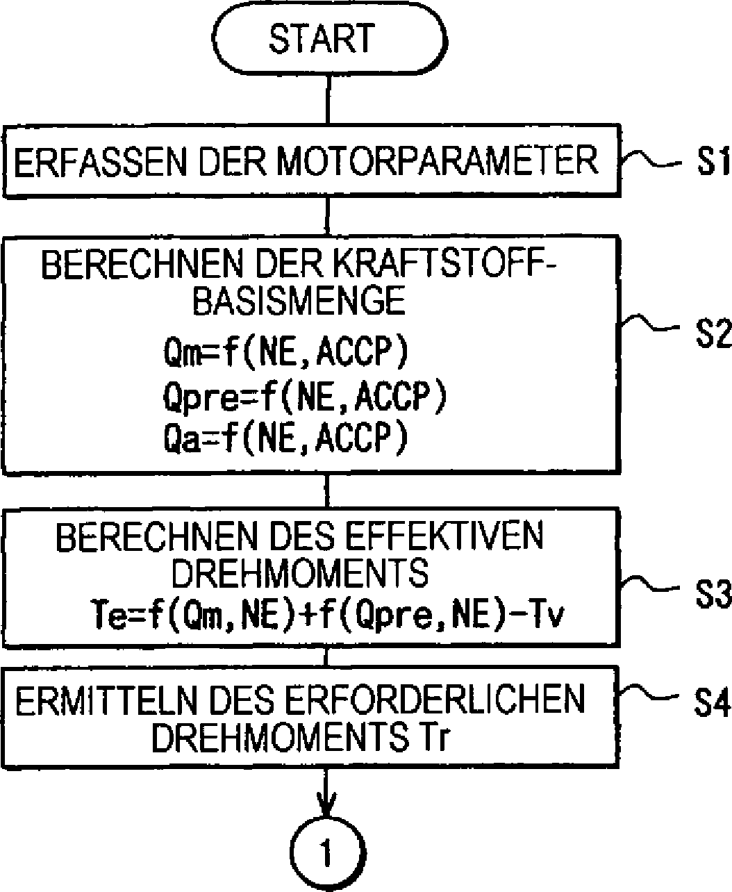
Unter Bezugnahme auf
Die Kraftstoffeinspritzmenge Q in einem Mehrstufenkraftstoffeinspritzzyklus wird in ein effektives Drehmoment Te umgewandelt. Insbesondere wird dieses effektive Drehmoment Te als Te = f(Qm, NE) + f(Qpre, NE) – Tv durch Subtrahieren eines Drehmomentsverlusts Tv von einer Summe des Drehmoments f(Qm, NE), das im Ansprechen auf die Haupteinspritzung erzeugt wird und des Drehmoments f(Qpre, NE), das im Ansprechen auf die Voreinspritzung erzeugt wird. Dieses effektive Drehmoment Te ist eine Schätzung des Drehmoments, das der Verbrennungsmotor mit der Zufuhr der berechneten Kraftstoffeinspritzmenge erzeugen wird. Der Drehmomentverlust Tv wird als das Drehmoment definiert, das auf Grund von Kolbenreibung in dem Verbrennungsmotor und dergleichen erzeugt wird. Das effektive Drehmoment Te kann durch weiteres Addieren eines Drehmoments f(Qpos, NE) geschätzt werden, das im Ansprechen auf die Nacheinspritzung erzeugt wird.The fuel injection amount Q in a multi-stage fuel injection cycle is converted into an effective torque Te. Specifically, this effective torque Te is expressed as Te = f (Qm, NE) + f (Qpre, NE) -Tv by subtracting a torque loss Tv from a sum of the torque f (Qm, NE) generated in response to the main injection the torque f (Qpre, NE) generated in response to the pilot injection. This effective torque Te is an estimate of the torque that the engine will produce with the supply of the calculated fuel injection amount. The torque loss Tv is defined as the torque generated due to piston friction in the internal combustion engine and the like. The effective torque Te may be estimated by further adding a torque f (Qpos, NE) generated in response to the post-injection.
Dann wird ein erforderliches Drehmoment Tr bei Schritt S4 ermittelt. Dieses erforderliches Drehmoment Tr kann durch Aufnehmen von Drehmomentwerten von verschiedenartigen elektronischen Steuereinheiten ermittelt werden, die die Fahrzeugfortbewegung und nicht die Kraftstoffeinspritzung steuern.Then, a required torque Tr is determined at step S4. This required torque Tr can be determined by taking torque values from various electronic control units that control vehicle travel rather than fuel injection.
Als nächstes wird bei Schritt S5 in
Bei Schritt S6 wird geprüft, ob die Drehmomentdifferenz ΔT, um welches das effektive Drehmoment Te erhöht werden soll, niedriger als ein Drehmomenterhöhungsgrenzwert dT ist. Wenn ΔT < dT (JA) gilt, wird auch dann, wenn das effektive Drehmoment Te um die volle Menge der Differenz ΔT erhöht wird, angenommen, dass kein Drehmomenterhöhungsstoß (Verbrennungsmotorbeschleunigungsstoß) verursacht wird. Daher wird die Gesamtmenge der Drehmomentdifferenz ΔT auf die entsprechende Kraftstoffeinspritzmenge zum Kompensieren des unzureichenden Drehmoments bei Schritt S7 umgewandelt.At step S6, it is checked whether the torque difference ΔT by which the effective torque Te is to be increased is lower than a torque increase threshold dT. If ΔT <dT (YES), even if the effective torque Te is increased by the full amount of the difference ΔT, it is assumed that no torque increase shock (engine acceleration shock) is caused. Therefore, the total amount of the torque difference ΔT is converted to the corresponding fuel injection amount for compensating for the insufficient torque at step S7.
Bei diesem Schritt S7 wird insbesondere eine Drehmomentsbeitragsmenge ΔTpre, um welche die Voreinspritzung einen Beitrag leisten wird, als ΔTpre = f(Ne, ACCP) × ΔT = K × ΔT durch Verwenden der Drehmomentumwandlungsdatenabbildung (Kennfeld) berechnet, welche Konstanten K als eine Funktion von Ne und ACCP definiert. Eine Drehmomentkorrekturmenge ΔTm, durch welche die Haupteinspritzung einen Beitrag leistet, wird als ΔTm = ΔT – ΔTpre berechnet. Die Haupteinspritzungskraftstoffkorrekturmenge ΔQm und die Voreinspritzungskraftstoffkorrekturmenge ΔQpre wird als ΔQm = f(NE, ΔTm) beziehungsweise ΔQpre = f(NE, ΔTpre) berechnet. Diese Korrekturmengen ΔQm und ΔQpre sind Teile einer Einpritzkorrekturmenge ΔQ. Des weiteren kann eine Drehmomentbeitragsmenge ΔTpos, durch welche die Voreinspritzung einen Beitrag leisten wird, auf ähnliche Weise wie ΔTpos berechnet werden, und kann eine Voreinspritzkraftstoffkorrekturmenge ΔQpos als ΔQpos = f(NE = ΔTpos) berechnet werden. Diese Werte können durch Verwenden von jeweiligen Datenabbildungen (Kennfeldern) ähnlich zu denjenigen ermittelt werden, die in
Wenn ΔT > dT (NEIN) bei Schritt S6 gilt, wird angenommen, dass, wenn das effektive Drehmoment Te um die vollständige Menge der Differenz ΔT erhöht wird, ein Drehmamenterhöhungsstoß (Verbrennungsmotorbeschleunigungsstoß) verursacht werden wird. Daher werden die Haupteinspritzungskorrekturmenge ΔQm und die Voreinspritzungskorrekturmenge ΔQpre auf jeweilige Korrekturgrenzwerte ΔQm beziehungsweise ΔQpre bei Schritt S8 begrenzt.If ΔT> dT (NO) at step S6, it is assumed that when the effective torque Te is increased by the full amount of the difference ΔT, a torque increase shock (engine acceleration shock) will be caused. Therefore, the main injection correction amount ΔQm and the pilot injection correction amount ΔQpre are limited to respective correction thresholds ΔQm and ΔQpre, respectively, at step S8.
Wenn ΔT < –R' bei Schritt S5 ist, was bedeutet, dass das effektive Drehmoment Te übermäßig ist, schreitet das Verfahren zu Schritt S10 weiter, um das effektive Drehmoment Te zu verringern. Der Schritt S10 und die nachfolgenden Schritte S11 und S12 werden auf die ähnliche Weise wie bei den Schritten S6, S7 beziehungsweise S8 durchgeführt. Jedoch wird dieses Verfahren bei den Schritten S10, S11 und S12 zum Verringern des Drehmoments durchgeführt.If ΔT <-R 'at step S5, which means that the effective torque Te is excessive, the process proceeds to step S10 to decrease the effective torque Te. Step S10 and subsequent steps S11 and S12 are performed in the similar manner as in steps S6, S7, and S8, respectively. However, this process is performed at steps S10, S11 and S12 for decreasing the torque.
Dann werden bei den Schritten S13 und S14 die Basiskraftstoffeinspritzmengen Qm und Qpre, die für die Haupteinspritzung und die Voreinspritzung bei Schritt S2 berechnet werden, mit den Korrekturmengen ΔQm und ΔQpre korrigiert, die bei den Schritten S7, S8, S11 und S12 berechnet werden, als Qm = Qm ± ΔQm beziehungsweise Qpre = Qpre ± ΔQpre. Die Nacheinspritzungskraftstoffmenge Qpos kann als Qpos = Qpos ± ΔQpos im folgenden Schritt S13 berechnet werden.Then, at steps S13 and S14, the basic fuel injection amounts Qm and Qpre calculated for the main injection and the pilot injection at step S2 are corrected with the correction amounts ΔQm and ΔQpre calculated at steps S7, S8, S11 and S12 Qm = Qm ± ΔQm or Qpre = Qpre ± ΔQpre. The post-injection fuel amount Qpos may be calculated as Qpos = Qpos ± ΔQpos in the following step S13.
Dann werden bei Schritt S15 verschiedenartige Kraftstoffeinspritzsteuerwerte (Anweisungswerte an die Einspritzvorrichtung) aus der vorstehend genannten Verbrennungsmotordrehzahl NE, der Haupteinspritzmenge Qm, dem Kraftstoffdruck Pc, der Voreinspritzmenge Qpre, der Nacheinspritzmenge Qpos und dergleichen berechnet. Insbesondere werden zum Steuern der Mehrstufenkraftstoffeinspritzung, wie in
Diese verschiedenartigen Steuerwerte Tmon, Tmoff, Tpreon, Tpreoff, Tposon und Tposoff werden bei Schritt S16 zum Steuern von Betätigungszeitpunkten der Kraftstoffeinspritzventile gesetzt, wie in
Gemäß dem vorstehend genannten Drehmomentsteuerverfahren wird eine Drehmomentkorrektur für jede Einspritzmengenberechnung in einem Mehrstufeneinspritzzyklus durch Verwenden von jeweiligen Drehmomentumwandlungsdatenabbildungen durchgeführt. Das heißt, dass die Drehmomentkorrektur auf der Grundlage von Raten des Drehmomentbeitrags von jeder Einspritzung in einem Mehrstufeneinspritzzyklus erhalten wird. Eine Entsprechung zwischen der Kraftstoffeinspritzmenge und dem Drehmoment wird verbessert und die Entsprechung zwischen der Verbrennungsmotorsteuerung und anderen Fahrzeugfortbewegungssteuerungen wird verbessert. Somit wird die Steuerbarkeit des Fahrzeugs verbessert.According to the above-mentioned torque control method, torque correction is performed for each injection quantity calculation in a multi-stage injection cycle by using respective torque conversion data maps. That is, the torque correction is obtained based on rates of torque contribution from each injection in a multi-stage injection cycle. A correspondence between the fuel injection amount and the torque is improved, and the correspondence between the engine control and other vehicle travel control is improved. Thus, the controllability of the vehicle is improved.
Das Drehmomentsteuerverfahren für Verbrennungsmotoren, die eine Voreinspritzung, eine Haupteinspritzung und eine Nacheinspritzung in einem Mehrstufeneinspritzzyklus durchführen können, ist somit hier offenbart, wobei die Basiskraftstoffeinspritzmenge Q jeder Einspritzung in dem Mehrstufeneinspritzzyklus berechnet wird S2, und das effektive Drehmoment Te des Verbrennungsmotors aus der Basiskraftstoffeinspritzmenge Q berechnet wird S3. Die Drehmomentdifferenz ΔT zwischen dem effektiven Drehmoment Te und dem erforderlichen Drehmoment Tr wird berechnet S5. Die Basiskraftstoffeinspritzmenge Q jeder Einspritzung wird in Entsprechung mit der Drehmomentdifferenz ΔT berechnet S5–S16.The torque control method for internal combustion engines that can perform a pilot injection, main injection, and post injection in a multi-stage injection cycle is thus disclosed herein, wherein the basic fuel injection amount Q of each injection in the multi-stage injection cycle is calculated S2, and the effective torque Te of the internal combustion engine is calculated from the basic fuel injection amount Q becomes S3. The torque difference ΔT between the effective torque Te and the required torque Tr is calculated S5. The basic fuel injection amount Q of each injection is calculated in accordance with the torque difference ΔT S5-S16.
Claims (7)
Applications Claiming Priority (2)
| Application Number | Priority Date | Filing Date | Title |
|---|---|---|---|
| JP2001132486A JP4314752B2 (en) | 2001-04-27 | 2001-04-27 | Torque control device for multi-stage injection engine and torque control method thereof |
| JPP132486/01 | 2001-04-27 |
Publications (2)
| Publication Number | Publication Date |
|---|---|
| DE10218552A1 DE10218552A1 (en) | 2002-10-31 |
| DE10218552B4 true DE10218552B4 (en) | 2015-09-10 |
Family
ID=18980492
Family Applications (1)
| Application Number | Title | Priority Date | Filing Date |
|---|---|---|---|
| DE10218552.2A Expired - Fee Related DE10218552B4 (en) | 2001-04-27 | 2002-04-25 | Torque control method for multi-stage fuel injection internal combustion engines |
Country Status (2)
| Country | Link |
|---|---|
| JP (1) | JP4314752B2 (en) |
| DE (1) | DE10218552B4 (en) |
Families Citing this family (18)
| Publication number | Priority date | Publication date | Assignee | Title |
|---|---|---|---|---|
| WO2003085249A1 (en) * | 2002-04-08 | 2003-10-16 | Robert Bosch Gmbh | Method for monitoring an internal combustion engine |
| JP2003343331A (en) | 2002-05-24 | 2003-12-03 | Denso Corp | Injection rate control device for internal combustion engine |
| DE10252988B3 (en) * | 2002-11-14 | 2004-06-09 | Siemens Ag | Method for determining the injection quantity of an internal combustion engine |
| DE10346970B3 (en) * | 2003-10-09 | 2004-11-18 | Siemens Ag | Controlling internal combustion engine involves determining fuel quantity base value from load parameter, corrected with value dependent on fuel pressure in feed device and nozzle needle displacement |
| EP1526267A3 (en) | 2003-10-21 | 2010-07-28 | Continental Automotive GmbH | Method and device for compensating the drift of an injector for an internal combustion engine with direct injection |
| DE102004025406B4 (en) * | 2004-05-24 | 2015-11-12 | Volkswagen Ag | Method for injection control of an internal combustion engine and correspondingly designed engine control |
| DE102004048008A1 (en) * | 2004-10-01 | 2006-04-06 | Robert Bosch Gmbh | Method for operating an internal combustion engine |
| US7895827B2 (en) * | 2006-09-28 | 2011-03-01 | GM Global Technology Operations LLC | Method and apparatus for controlling engine operation during regeneration of an exhaust aftertreatment system |
| FR2910549A1 (en) * | 2006-12-21 | 2008-06-27 | Renault Sas | Injector drift correcting method for e.g. diesel engine of vehicle, involves determining drift correction value of injector to be added to nominal set point value by utilizing indicated average torque estimation for cylinders |
| FR2910550A1 (en) * | 2006-12-21 | 2008-06-27 | Renault Sas | Injector drift correction method for e.g. motor vehicle's direct injection oil engine, involves comparing actual injected and set point fuel quantities, and determining correction to be carried out to set point by using torque estimation |
| FR2910547B1 (en) * | 2006-12-21 | 2009-01-30 | Renault Sas | METHOD FOR ESTIMATING THE TORQUE OF A VEHICLE ENGINE PROVIDED BY INJECTION PATTERN COMPRISING Q INJECTIONS |
| FR2917460A1 (en) * | 2007-06-12 | 2008-12-19 | Renault Sas | Indicated average torque correcting method for e.g. petrol engine, involves controlling quantity of fuel to be injected based on comparison result between setting torque value and indicated average torque |
| DE102007061732A1 (en) * | 2007-12-20 | 2009-06-25 | Robert Bosch Gmbh | Internal combustion engine operating method for motor vehicle, involves plausibilizing parameter determined in function level to control engine and another parameter determined in function monitoring level to monitor engine's function |
| FR2935750A1 (en) * | 2008-09-10 | 2010-03-12 | Renault Sas | Fuel quantity correcting system for direct or indirect injection type diesel engine of motor vehicle, has controller whose database has cartographic quantity compared with real quantity to correct real quantity when quantities are different |
| JP5854203B2 (en) * | 2011-11-04 | 2016-02-09 | 三菱自動車工業株式会社 | Fuel injection control device for internal combustion engine |
| JP5854204B2 (en) * | 2011-11-14 | 2016-02-09 | 三菱自動車工業株式会社 | Fuel injection control device for internal combustion engine |
| EP2754879A1 (en) * | 2013-01-15 | 2014-07-16 | Robert Bosch GmbH | Method and device for operating an internal combustion engine |
| BR112019000044B1 (en) * | 2016-07-13 | 2023-01-17 | Nissan Motor Co., Ltd | ENGINE CONTROL METHOD AND ENGINE CONTROL DEVICE |
Citations (4)
| Publication number | Priority date | Publication date | Assignee | Title |
|---|---|---|---|---|
| DE19632650C1 (en) * | 1996-08-13 | 1998-03-12 | Siemens Ag | Method for suppressing torque jumps when operating an internal combustion engine |
| DE19712143A1 (en) * | 1997-03-22 | 1998-09-24 | Bosch Gmbh Robert | Control procedure for internal combustion engine |
| DE19749815A1 (en) * | 1997-11-11 | 1999-05-12 | Bosch Gmbh Robert | Device and method for determining the amount of fuel injected |
| DE10019466A1 (en) * | 1999-04-20 | 2000-11-02 | Honda Motor Co Ltd | Ignition timing control system for internal combustion engine corrects ignition timing if difference between required fuel injection end timing and certain timing is less than threshold |
-
2001
- 2001-04-27 JP JP2001132486A patent/JP4314752B2/en not_active Expired - Lifetime
-
2002
- 2002-04-25 DE DE10218552.2A patent/DE10218552B4/en not_active Expired - Fee Related
Patent Citations (4)
| Publication number | Priority date | Publication date | Assignee | Title |
|---|---|---|---|---|
| DE19632650C1 (en) * | 1996-08-13 | 1998-03-12 | Siemens Ag | Method for suppressing torque jumps when operating an internal combustion engine |
| DE19712143A1 (en) * | 1997-03-22 | 1998-09-24 | Bosch Gmbh Robert | Control procedure for internal combustion engine |
| DE19749815A1 (en) * | 1997-11-11 | 1999-05-12 | Bosch Gmbh Robert | Device and method for determining the amount of fuel injected |
| DE10019466A1 (en) * | 1999-04-20 | 2000-11-02 | Honda Motor Co Ltd | Ignition timing control system for internal combustion engine corrects ignition timing if difference between required fuel injection end timing and certain timing is less than threshold |
Also Published As
| Publication number | Publication date |
|---|---|
| JP4314752B2 (en) | 2009-08-19 |
| JP2002327637A (en) | 2002-11-15 |
| DE10218552A1 (en) | 2002-10-31 |
Similar Documents
| Publication | Publication Date | Title |
|---|---|---|
| DE10218552B4 (en) | Torque control method for multi-stage fuel injection internal combustion engines | |
| EP1660766B1 (en) | Method for controlling the transition of a direct-injection spark-ignition engine | |
| DE102017008362B4 (en) | Control or regulating device for a vehicle, method for controlling or regulating the driving force transmission path, and computer program product | |
| DE19912506A1 (en) | Control system for automatic drive for controlling at least one clutch using oil pressure of automatic gear box connected with engine output shaft which engages or disengages to carry out gear change | |
| DE10231143B4 (en) | Method for controlling the valve lift of discretely adjustable intake valves of a multi-cylinder internal combustion engine | |
| DE19631986A1 (en) | Control unit for vehicle direct injection IC petrol engine | |
| DE10046597B4 (en) | Control system for direct injection engines | |
| DE102008003581A1 (en) | Exhaust gas temperature reducing method for engine i.e. petrol engine, of motor vehicle, involves reducing exhaust gas temperature by shifting ignition angle of engine before upper dead center for performing advance ignition | |
| DE102019107775A1 (en) | Control unit and method for operating a hybrid drive with a drag torque-reduced internal combustion engine | |
| EP1649153B1 (en) | Method and device for controlling the transition between normal operation and overrun fuel cut-off operation of an otto engine operated with direct fuel injection | |
| EP0764778B1 (en) | Control method for the fuel injection of a diesel engine | |
| EP1190167B1 (en) | Method and device for operating an internal combustion engine with direct gas injection | |
| DE102012000697B4 (en) | Method for reducing particulate emissions of an engine in transient mode | |
| EP1412630A1 (en) | Method and device for operating a drive engine of a vehicle | |
| DE102006005701B4 (en) | Method and device for operating a drive unit, computer program product and computer program | |
| DE10249098A1 (en) | Method and device for controlling a drive unit with an internal combustion engine | |
| DE10058354B4 (en) | Method and device for controlling the drive unit of a vehicle | |
| DE102004013812A1 (en) | Method for operating a hybrid motor vehicle | |
| DE102008054773A1 (en) | Retarded ignition angle limiting value correcting method for otto engine, involves determining irregular operation measure, and correcting retarded ignition angle limiting value by control ignition angle based on measure | |
| DE10042842B4 (en) | Method and device for starting the engine in internal combustion engines operated with gasoline direct injection, in particular with a plurality of cylinder banks | |
| DE69920074T2 (en) | Electronic fuel injection device for diesel engine | |
| DE10233578B4 (en) | Method and device for controlling the drive unit of a vehicle | |
| DE69803641T2 (en) | Torque control device for an internal combustion engine mounted on a motor vehicle | |
| DE102020116456A1 (en) | Method for operating a drive unit of a motor vehicle | |
| DE102016108914B4 (en) | Method and system for supplying fuel to an engine |
Legal Events
| Date | Code | Title | Description |
|---|---|---|---|
| 8110 | Request for examination paragraph 44 | ||
| 8125 | Change of the main classification |
Ipc: F02D 41/00 AFI20051017BHDE |
|
| R016 | Response to examination communication | ||
| R079 | Amendment of ipc main class |
Free format text: PREVIOUS MAIN CLASS: F02D0041000000 Ipc: F02D0041400000 |
|
| R079 | Amendment of ipc main class |
Free format text: PREVIOUS MAIN CLASS: F02D0041000000 Ipc: F02D0041400000 Effective date: 20140805 |
|
| R016 | Response to examination communication | ||
| R018 | Grant decision by examination section/examining division | ||
| R084 | Declaration of willingness to licence | ||
| R020 | Patent grant now final | ||
| R119 | Application deemed withdrawn, or ip right lapsed, due to non-payment of renewal fee |