DE102019114532A1 - Block and block arrangement - Google Patents
Block and block arrangement Download PDFInfo
- Publication number
- DE102019114532A1 DE102019114532A1 DE102019114532.5A DE102019114532A DE102019114532A1 DE 102019114532 A1 DE102019114532 A1 DE 102019114532A1 DE 102019114532 A DE102019114532 A DE 102019114532A DE 102019114532 A1 DE102019114532 A1 DE 102019114532A1
- Authority
- DE
- Germany
- Prior art keywords
- head
- foot
- recess
- connecting element
- base body
- Prior art date
- Legal status (The legal status is an assumption and is not a legal conclusion. Google has not performed a legal analysis and makes no representation as to the accuracy of the status listed.)
- Ceased
Links
Images


Classifications
-
- A—HUMAN NECESSITIES
- A63—SPORTS; GAMES; AMUSEMENTS
- A63H—TOYS, e.g. TOPS, DOLLS, HOOPS OR BUILDING BLOCKS
- A63H33/00—Other toys
- A63H33/04—Building blocks, strips, or similar building parts
- A63H33/10—Building blocks, strips, or similar building parts to be assembled by means of additional non-adhesive elements
- A63H33/108—Building blocks, strips, or similar building parts to be assembled by means of additional non-adhesive elements with holes
-
- A—HUMAN NECESSITIES
- A63—SPORTS; GAMES; AMUSEMENTS
- A63H—TOYS, e.g. TOPS, DOLLS, HOOPS OR BUILDING BLOCKS
- A63H33/00—Other toys
- A63H33/04—Building blocks, strips, or similar building parts
- A63H33/10—Building blocks, strips, or similar building parts to be assembled by means of additional non-adhesive elements
- A63H33/107—Building blocks, strips, or similar building parts to be assembled by means of additional non-adhesive elements using screws, bolts, nails, rivets, clamps
-
- A—HUMAN NECESSITIES
- A63—SPORTS; GAMES; AMUSEMENTS
- A63H—TOYS, e.g. TOPS, DOLLS, HOOPS OR BUILDING BLOCKS
- A63H33/00—Other toys
- A63H33/04—Building blocks, strips, or similar building parts
- A63H33/10—Building blocks, strips, or similar building parts to be assembled by means of additional non-adhesive elements
- A63H33/12—Perforated strips or the like assembled by rods, bolts, or the like
Landscapes
- Connection Of Plates (AREA)
Abstract
Die Erfindung betrifft einen Baustein (1, 26, 27, 28, 29, 30) mit einem Grundkörper (2) und mit einem Verbindungselement (3) mit einem Kopfabschnitt (14). Der Kopfabschnitt (14) ragt auf einer Kopfseite (4) des Grundkörpers (2) über eine Kopffläche (6) des Grundkörpers (2) hinaus. Der Baustein (1, 26, 27, 28, 29, 30) kann mit dem Kopfabschnitt (14) mit einer auf einer der Kopfseite (4) gegenüberliegenden Fußseite (5) angeordneten und in eine Fußfläche (7) hineinragenden Fußausnehmung (17) eines weiteren Grundkörpers (2) in Eingriff gebracht werden. Das Verbindungselement (3) ist lösbar an dem Grundkörper (2) des Bausteins (1, 26, 27, 28, 29, 30) festgelegt. Der Kopfabschnitt (14) weist eine zu einem distalen Endbereich (15) hin verjüngende konische Formgebung auf. Eine Formgebung der Fußausnehmung (17) ist an die Formgebung des Kopfabschnitts (14) angepasst.
Description
Die Erfindung betrifft einen Baustein mit einem Grundkörper und mit einem Verbindungselement mit einem Kopfabschnitt, wobei der Kopfabschnitt auf einer Kopfseite des Grundkörpers über eine Kopffläche des Grundkörpers hinausragt, wobei der Baustein mit dem Kopfabschnitt mit einer auf einer der Kopfseite gegenüberliegenden Fußseite angeordneten und in eine Fußfläche hineinragenden Fußausnehmung eines weiteren Grundkörpers in Eingriff gebracht werden kann und wobei das Verbindungselement lösbar an dem Grundkörper des Bausteins festgelegt ist.The invention relates to a building block with a base body and with a connecting element with a head portion, wherein the head portion protrudes on a head side of the base body over a head surface of the base body, wherein the block with the head portion arranged with a lying on one side of the head side foot and in a foot surface protruding Fußausnehmung another body can be brought into engagement and wherein the connecting element is releasably fixed to the main body of the block.
Aus der Praxis sind verschiedenartige miteinander verbindbare Bausteine bekannt. In der Druckschrift
In der Druckschrift
Daher wird es als eine Aufgabe der vorliegenden Erfindung angesehen, einen Baustein so auszugestalten, dass die oben beschriebenen Nachteile beseitigt werden.Therefore, it is considered to be an object of the present invention to design a device in such a way that the disadvantages described above are eliminated.
Diese Aufgabe wird erfindungsgemäß dadurch gelöst, dass der Kopfabschnitt eine zu einem distalen Endbereich hin verjüngende konische Formgebung aufweist und wobei eine Formgebung der Fußausnehmung an die Formgebung des Kopfabschnitts angepasst ist. Bei einer derartigen Ausgestaltung kann der Baustein mit dem konisch geformten Kopfabschnitt des an dem Grundkörper des Bauteils lösbar festgelegten Verbindungselements in der Fußausnehmung eines weiteren Bausteins festgelegt werden. Der Grundkörper des Bausteins kann mit seiner Fußseite auf einem Untergrund angeordnet werden. Das Verbindungselement kann an dem Grundkörper lösbar festgelegt werden und danach ein weiterer Grundkörper mit seiner Fußseite auf der Kopfseite des auf dem Untergrund angeordneten Grundkörpers angeordnet und mit dem in die Fußausnehmung eingreifenden Kopfabschnitt des Verbindungselement befestigt werden. Somit können mehrere Bausteine übereinander angeordnet und miteinander verbunden auf dem Untergrund aufgebaut werden. Ohne Verbindungselement weist der Grundkörper eine bündig abschließende Kopffläche auf.This object is achieved in that the head portion has a conical shape tapering towards a distal end portion and wherein a shape of the Fußausnehmung is adapted to the shape of the head portion. In such an embodiment, the block with the conically shaped head portion of the releasably secured to the main body of the component connecting element in the Fußausnehmung another block can be defined. The main body of the block can be arranged with its foot on a substrate. The connecting element can be releasably secured to the base body and then arranged a further base body with its base side on the head side of the base body arranged on the ground and fixed with the engaging in the foot recess head portion of the connecting element. Thus, several blocks can be arranged one above the other and connected to each other on the ground. Without a connecting element, the main body has a flush final head surface.
Der Baustein kann so dimensioniert sein, dass der Baustein sich als Baustein für ein tragbares Steckspielsystem zum Spielen und Bauen für Kinder und für Erwachsene eignet. Alternativ kann der Baustein auch so dimensioniert sein, dass der Baustein sich als Baustein für ein Konstruktionssystem zum Aufbau beispielsweise von Sitzmöbeln eignet. Es ist auch möglich und erfindungsgemäß optional vorgesehen, dass der Baustein so dimensioniert ist, dass der Baustein sich als Baustein eines Konstruktionssystems für Gebäude eignet.The device may be sized to make the device a building block for a portable gaming and play system for children and adults. Alternatively, the module can also be dimensioned so that the module is suitable as a building block for a construction system for the construction of, for example, seating furniture. It is also possible and optionally provided according to the invention that the module is dimensioned so that the module is suitable as a building block of a construction system for buildings.
Der Grundkörper und gegebenenfalls das Verbindungselement sind insbesondere bei einer Ausgestaltung als tragbares Steckspielsystem in vorteilhafter Weise aus einem leichten Werkstoff gefertigt. Vorzugsweise sind der Grundkörper und gegebenenfalls das Verbindungselement aus einem schwer entflammbaren Werkstoff gefertigt. Vorteilhafterweise ist eine Oberfläche des Werkstoffs des Grundkörpers und des Verbindungselements so ausgestaltet, dass der Grundkörper und das Verbindungselement miteinander verklebbar sind. Der Grundkörper und das Verbindungselement können aus einem aus Erdöl gefertigten, synthetischen Kunststoff wie beispielsweise Polyethylen, Polypropylen, Polyester, Polycarbonat, Polyacetat, Polyamid, Polystyrol, Polyvinylalkohol, Polymethylmethacrylat, Acrylnitril-Butadien-Styrol oder einer Kombination daraus gefertigt sein. Es ist auch möglich und erfindungsgemäß optional vorgesehen, dass der Grundkörper und das Verbindungselement aus einem nicht-erdölbasierten Bio-Kunststoff, insbesondere aus nachwachsenden Rohstoffen wie beispielsweise Bio-Polyester, Bio-Polyesteramid, Polylactid, Polyhydroxybuttersäure, Polyethylenterephthalat, thermoplastischer Stärke oder einer Kombination daraus gefertigt sind. Der Grundkörper und das Verbindungselement können auch aus einer Kombination aus dem synthetischen Kunststoff und dem Biokunststoff gefertigt sein.The base body and, where appropriate, the connecting element are advantageously made of a lightweight material, in particular in one embodiment as a portable plug play system. Preferably, the base body and optionally the connecting element are made of a flame-retardant material. Advantageously, a surface of the material of the base body and the connecting element is designed so that the base body and the connecting element can be bonded together. The main body and the connector may be made of a petroleum-made synthetic resin such as polyethylene, polypropylene, polyester, polycarbonate, polyacetate, polyamide, polystyrene, polyvinyl alcohol, polymethyl methacrylate, acrylonitrile-butadiene-styrene, or a combination thereof. It is also possible and optionally provided according to the invention for the base body and the connecting element to be made from a non-petroleum-based bio-plastic, in particular from renewable raw materials such as, for example, organic polyester, biopolyesteramide, polylactide, polyhydroxybutyric acid, polyethylene terephthalate, thermoplastic starch or a combination thereof are made. The base body and the connecting element can also be made of a combination of the synthetic plastic and the bioplastic.
Im Falle des Konstruktionssystems für Gebäude können der Grundkörper und das Verbindungselement auch aus einem mineralischen Werkstoff wie Beton gefertigt sein. Das Verbindungselement kann darüber hinaus aus Stahlbeton gefertigt sein, um Scherkräfte besser aufnehmen zu können. Die Bausteine können als Hohlsteine oder massiv ausgebildet sein. Die Kanten des Grundkörpers und gegebenenfalls des Verbindungselements können abgerundet oder angefast sein.In the case of the construction system for buildings, the base body and the connecting element may also be made of a mineral material such as concrete. In addition, the connecting element can be made of reinforced concrete in order to absorb shear forces better. The blocks can be designed as hollow stones or solid. The edges of the body and possibly the connecting element may be rounded or chamfered.
Gemäß einer vorteilhaften Ausgestaltung des Bausteins ist vorgesehen, dass der Grundkörper eine auf der Kopfseite angeordnete Kopfausnehmung aufweist, wobei das Verbindungselement mit einem Fußabschnitt in der Kopfausnehmung lösbar festgelegt ist, wobei der Fußabschnitt eine sich zu einem distalen Endbereich des Fußabschnitts hin verjüngende konische Formgebung aufweist und wobei die Formgebung der Kopfausnehmung an die Formgebung des Fußabschnitts angepasst ist. Somit kann das Befestigungselement schnell und einfach mit dem Fußabschnitt in der Kopfausnehmung lösbar festlegbar sein. According to an advantageous embodiment of the module, it is provided that the base body has a head recess arranged on the head, wherein the connecting element is releasably secured with a foot portion in the head recess, wherein the foot portion has a tapered to a distal end portion of the foot portion conical shape and wherein the shape of the head recess is adapted to the shape of the foot portion. Thus, the fastener can be quickly and easily releasably secured to the foot portion in the head recess.
In vorteilhafter Weise ist vorgesehen, dass das Verbindungselement entlang einer Verbindungselementachse symmetrisch ausgebildet ist. Mit dem symmetrischen, doppelkonischen Verbindungselement kann ein Verbinden mehrerer Grundkörper mit einer an das symmetrische Verbindungselement angepassten konischen Fuß- und Kopfausnehmung erleichtert sein. Der Grundkörper kann sowohl mit seiner Kopf- als auch mit seiner Fußseite auf dem Untergrund angeordnet werden. Das symmetrische, doppelkonische Verbindungselement kann mit einer seiner Abschnitte schnell und einfach in die dem Untergrund gegenüberliegende Ausnehmung eingeführt werden und ist somit lösbar an dem Grundkörper festgelegt. Ein weiterer Grundkörper kann mit seiner Kopf- als auch mit seiner Fußseite auf dem auf dem Untergrund angeordneten Grundkörper angeordnet werden. Der über die dem Untergrund abgewandte Oberfläche des auf dem Untergrund angeordneten Grundkörpers herausragende konische Abschnitt des Verbindungselements kann somit in die dem Grundkörper zugewandte konische Ausnehmung des weiteren Grundkörpers eingreifen, um den weiteren Grundkörper an dem auf dem Untergrund angeordneten Grundkörper festzulegen.It is advantageously provided that the connecting element is formed symmetrically along a connecting element axis. With the symmetrical, double-conical connecting element connecting a plurality of base body can be facilitated with a matched to the symmetrical connecting element conical foot and head recess. The main body can be arranged with its head as well as with its foot on the ground. The symmetrical, double-conical connecting element can be quickly and easily inserted into one of its sections in the base of the opposite recess and is thus releasably fixed to the body. Another base body can be arranged with its head as well as with its foot on the base body arranged on the ground. The on the background facing away from the surface of the surface arranged on the base body outstanding conical portion of the connecting element can thus engage in the base body facing conical recess of the other body to set the other body to the arranged on the ground body.
Bei einer vorteilhaften Umsetzung des Erfindungsgedankens ist vorgesehen, dass die Kopffläche und die Fußfläche zueinander parallel liegen und eine Kopfausnehmungsachse der Kopfausnehmung und eine Fußausnehmungsachse der Fußausnehmung senkrecht zu der Kopffläche liegen und wobei die Kopfausnehmungsachse und die Fußausnehmungsachse eine Hauptachse des Grundkörpers senkrecht schneiden. Die Hauptachse des Grundkörpers liegt zwischen der Kopffläche und Fußfläche und erstreckt sich parallel zu der Kopffläche.In an advantageous implementation of the inventive concept, it is provided that the head face and the foot face are parallel to each other and a Kopfausnehmungsachse the Kopfausnehmung and Fußausnehmungsachse the Fußausnehmung perpendicular to the top surface and wherein the Kopfausnehmungsachse and Fußausnehmungsachse intersect a major axis of the body perpendicular. The main axis of the main body lies between the head surface and foot surface and extends parallel to the head surface.
In vorteilhafter Weise ist vorgesehen, dass die Kopfausnehmungsachse und die Fußausnehmungsachse in einer gemeinsamen Ausnehmungsachse liegen. Im Falle eines symmetrischen Verbindungselements kann der Grundkörper entlang der Ausnehmungsachse symmetrisch ausgebildet sein. Um den Grundkörper einfacher fertigbar auszugestalten ist vorzugsweise vorgesehen, dass die Kopfausnehmung und die Fußausnehmung mit der gemeinsamen Ausnehmungsachse an gegenüberliegenden Stirnseiten der Kopfausnehmung und der Fußausnehmung aneinander angrenzen, so dass eine von der Kopfseite bis zu der Fußseite durchgehende Verbindungsausnehmung gebildet ist.It is advantageously provided that the head recess axis and the foot recess axis lie in a common recess axis. In the case of a symmetrical connecting element, the base body may be formed symmetrically along the Ausnehmungsachse. In order to design the base body in a manner that is easier to manufacture, it is preferably provided that the head recess and the foot recess adjoin one another with the common recess axis on opposite end faces of the head recess and the foot recess, so that a connecting recess extending from the head side to the foot side is formed.
In vorteilhafter Weise ist vorgesehen, dass der in der Kopfausnehmung angeordnete Fußabschnitt eines Verbindungselements an einem Kopfabschnitt eines anderen angrenzenden Verbindungselements lösbar festlegbar ist. Der Kopfabschnitt kann beispielsweise einen an eine Gewindeausnehmung des Fußabschnitts angepassten Gewindestift aufweisen, so dass die zwei Verbindungselemente an dem Grundkörper durch Verschrauben formschlüssig festlegbar sind. Somit kann eine Vielzahl von übereinander angeordneten Grundkörpern mit den miteinander verschraubten Grundkörpern aneinander festgelegt werden.It is advantageously provided that the foot section of a connecting element arranged in the head recess can be releasably secured to a head section of another adjacent connecting element. The head section may, for example, have a threaded pin adapted to a threaded recess of the foot section, so that the two connecting elements can be fixed in a form-fitting manner to the base body by screwing. Thus, a plurality of superimposed main bodies can be fixed to each other with the basic bodies screwed together.
Bei einer vorteilhaften Umsetzung des Erfindungsgedankens ist vorgesehen, dass der Grundkörper durch sich jeweils von der Kopffläche bis zu der Fußfläche erstreckende Seitenflächen begrenzt ist, wobei die Seitenflächen die Kopffläche und die Fußfläche in einem rechten Winkel schneiden. Somit können die Grundkörper mehrerer Bausteine nebeneinander auf dem Untergrund mit aneinander anliegenden Seitenflächen angeordnet werden.In an advantageous implementation of the inventive concept, it is provided that the base body is delimited by side surfaces extending from the top surface to the bottom surface, wherein the side surfaces intersect the top surface and the bottom surface at a right angle. Thus, the main body of several building blocks can be arranged side by side on the ground with adjoining side surfaces.
Vorzugsweise ist vorgesehen, dass in einem entlang der Hauptachse zwischen einem jeweiligen Ende des Grundkörpers und einem Schnittpunkt der mit dem jeweiligen Ende des Grundkörpers benachbarten Ausnehmungsachse mit der Hauptachse ausgebildeten Grundkörperendbereich des Grundkörpers ein minimaler Abstand der Seitenflächen zu der Ausnehmungsachse annähernd konstant ist, wobei ein jeder der Grundkörperendbereiche von mindestens drei Seitenflächen begrenzt ist.Preferably, it is provided that in a along the main axis between a respective end of the base body and an intersection of the respective end of the base body adjacent Ausnehmungsachse formed with the main axis Grundkörperendbereich the body minimum distance of the side surfaces to the Ausnehmungsachse is approximately constant, each one the Grundkörperendbereiche of at least three side surfaces is limited.
In vorteilhafter Weise ist vorgesehen, dass der Grundkörper als gerades Prisma mit einer achteckigen Grundfläche ausgebildet ist. Bei einer derartigen Ausgestaltung des Erfindungsgedankens kann der Grundkörper in jedem der zwei Endbereiche von fünf Seitenflächen begrenzt sein, wobei sich angrenzende Seitenflächen in einem Winkel von 45 Grad schneiden. Ein solcher Grundkörper kann mit einer der Seitenflächen benachbart zu einer Seitenfläche eines weiteren Grundkörpers unter einem Winkel zwischen den Hauptachsen der zwei Grundkörper von 0 Grad, 45 Grad, 90 Grad und 135 Grad anordenbar sein.Advantageously, it is provided that the base body is designed as a straight prism with an octagonal base. In such an embodiment of the inventive concept, the main body may be delimited in each of the two end regions of five side surfaces, wherein adjacent side surfaces intersect at an angle of 45 degrees. Such a body may be locatable with one of the side surfaces adjacent to a side surface of another body at an angle between the major axes of the two bodies of 0 degrees, 45 degrees, 90 degrees, and 135 degrees.
Bei einer vorteilhaften Umsetzung des Erfindungsgedankens ist vorgesehen, dass ein Halbkonuswinkel zwischen der Verbindungselementachse und einer auf einer Mantelfläche des Fußabschnitts und/oder des Kopfabschnitts liegenden und die Verbindungselementachse schneidenden Linie bei einer daran angepassten Formgebung der Kopfausnehmung und/oder der Fußausnehmung so gewählt ist, dass der Halbkonuswinkel 0,001 bis 1 Grad kleiner, vorzugsweise 0,001 bis 0,5 Grad kleiner und besonders bevorzugt 0,001 bis 0,2 Grad kleiner ist als der Arkustangens einer Haftreibungszahl für eine Materialkombination des Grundkörpers und des Verbindungselements. Somit kann bei einem in die Kopfausnehmung beziehungsweise in die Fußausnehmung eingeführten Fußabschnitt beziehungsweise Kopfabschnitt gerade noch keine Selbsthemmung auftreten, so dass der jeweilige Abschnitt sich nicht in der jeweiligen Ausnehmung verklemmt ohne gegebenenfalls zu leicht aus der jeweiligen Ausnehmung zu fallen.In an advantageous implementation of the inventive concept it is provided that a half-cone angle between the connecting element axis and one on a lateral surface of the foot section and / or the head section and the connecting element axis intersecting line is selected with an adapted shaping of the head recess and / or the Fußausnehmung that the half-cone angle is 0.001 to 1 degree smaller, preferably 0.001 to 0.5 degrees smaller and more preferably 0.001 to
Die Erfindung betrifft auch eine Bausteinanordnung mit mindestens zwei wie vorangehend beschriebenen Bausteinen.The invention also relates to a device arrangement with at least two components as described above.
Bei der Bausteinanordnung mit den mindestens zwei Bausteinen ist in vorteilhafter Weise vorgesehen, dass die Grundkörper der zwei Bausteine mit dem Verbindungselement miteinander verbindbar sind. Der Grundkörper eines ersten Bausteins ist mit seiner Fußfläche an der Kopffläche eines zweiten Bausteins angeordnet mit dem Kopfabschnitt des zweiten Bausteins in die Fußausnehmung des Grundkörpers des ersten Bausteins eingreifend verbindbar.In the device arrangement with the at least two components, it is advantageously provided that the base bodies of the two components can be connected to one another by means of the connection element. The main body of a first module is arranged with its foot surface on the top surface of a second module arranged engaging with the head portion of the second module in the Fußausnehmung of the main body of the first module.
Bei der Bausteinanordnung mit den mindestens zwei Bausteinen ist vorzugsweise vorgesehen, dass die Grundkörper der zwei Bausteine zwei entlang der Hauptachse in einem Versetzungsabstand voneinander beabstandete Fußausnehmungen und/oder Kopfausnehmungen aufweisen, so dass die Grundkörper der zwei Bausteine um den Versetzungsabstand versetzt mit dem Verbindungselement miteinander verbindbar sind. Somit kann bei einer Vielzahl von Bausteinen aus den um den Versetzungsabstand versetzt verbundenen Bausteinen beispielsweise eine Wand aufgebaut werden.In the block arrangement with the at least two components, it is preferably provided that the base bodies of the two components have two foot recesses and / or head recesses spaced apart along the main axis at a dislocation distance, so that the base bodies of the two components can be connected to one another by the offset distance with the connection element are. Thus, in the case of a plurality of components, for example, a wall can be built up from the components offset by the offset distance.
Bei einer Bausteinanordnung mit mindestens drei Bausteinen ist in vorteilhafter Weise vorgesehen, dass die Grundkörper zweier Bausteine mit den die jeweiligen Grundkörperendbereiche begrenzenden Seitenflächen in einer Bausteinanordnung aneinander angeordnet mit einem an den zwei Grundkörpern mit jeweils einem Verbindungselement verbundenen Grundkörper eines dritten Bausteins in ihrer Bausteinausrichtung fixierbar sind. Bei dem in jedem der zwei Endbereiche von fünf Seitenflächen begrenzten und mit sich angrenzenden Seitenflächen in einem Winkel von 45 Grad schneidenden Grundkörper können die Bausteine in der Bausteinausrichtung von 0 Grad, 45 Grad, 90 Grad und 135 Grad zueinander angeordnet fixiert sein. Dadurch ergeben sich im Vergleich zu quaderförmig ausgestalteten Bausteinen mehr mögliche Bausteinausrichtungen. Dies kann beispielsweise bei dem Steckspielsystem die Kreativität von mit dem Steckspielsystem spielenden Personen anregen.In the case of a block arrangement having at least three components, it is advantageously provided that the base bodies of two components can be fixed in their component alignment with the side surfaces delimiting the respective base end regions in a block arrangement with a base body of a third component connected to the two base bodies with one connection element each , With the base body intersected in each of the two end regions of five side surfaces and adjoining side surfaces at a 45 degree angle, the devices may be fixed in the device alignment of 0 degrees, 45 degrees, 90 degrees, and 135 degrees to each other. This results in more possible device alignments compared to parallelepiped designed blocks. This can, for example, in the plug-in game system stimulate the creativity of playing with the plug and play system people.
Vorzugsweise ist vorgesehen, dass die Bausteinanordnung Abschlusselemente aufweist, wobei die Abschlusselemente in die Kopfausnehmung und/oder in die Fußausnehmung einsteckbar sind und welche eingesteckt mit der Kopffläche und/oder der Fußfläche bündig abschließen. Die Abschlusselemente können an die konische Formgebung der Verbindungselemente angepasst sein. Es ist auch möglich und erfindungsgemäß vorgesehen, dass die Abschlusselemente mit den miteinander lösbar festlegbaren Verbindungselementen verbindbar sind. Es ist möglich und erfindungsgemäß optional vorgesehen, dass die Bausteinanordnung, insbesondere bei dem Konstruktionssystem zum Aufbau von Sitzmöbeln, mit seiner Fußfläche mit der Kopffläche der Bausteine verbindbare Sitzelemente mit einem mindestens bereichsweise an seiner Kopffläche angeordneten, gepolsterten Polsterteil aufweist. Um insbesondere den mit dem tragbaren Steckspielsystem spielenden Personen weitere kreative Möglichkeiten beim Spielen mit dem Steckspielsystem zu ermöglichen, ist in vorteilhafter Weise vorgesehen, dass die Bausteinanordnung mit seiner jeweiligen Fußfläche an der Kopfseite der Bausteine verbindbare Designelemente mit einem an seiner Kopfseite angeordneten Designteil wie beispielsweise einem Turm, einer Kirchturmspitze, oder dergleichen aufweist.It is preferably provided that the module arrangement has termination elements, wherein the termination elements can be inserted into the head recess and / or into the foot recess and which, when inserted, are flush with the top surface and / or the bottom surface. The end elements can be adapted to the conical shape of the connecting elements. It is also possible and provided according to the invention that the closing elements can be connected to the fasteners which can be fastened together releasably. It is possible and according to the invention optionally provided that the block assembly, in particular in the construction system for the construction of seating furniture, with its foot surface with the head surface of the blocks connectable seat elements having a at least partially arranged on its top surface, padded upholstered part. In order to enable in particular the players playing with the portable plug-in game system further creative possibilities when playing with the plug-in game system, it is advantageously provided that the device assembly with its respective foot surface on the head side of the building blocks connectable design elements with a arranged on its head side design part such as a Tower, a spire, or the like.
Bei der Bausteinanordnung mit den Grundkörpern mit den zwei entlang der Hauptachse in dem Versetzungsabstand voneinander beabstandeten, in den Endbereichen angeordneten Fußausnehmungen ist vorzugsweise vorgesehen, dass die Bausteinanordnung Verlängerungssteine mit zwei entlang einer Hauptachse in Endbereichen angeordnete, in einem Verlängerungsabstand beabstandete Fußausnehmungen aufweist, wobei der Verlängerungsabstand größer ist als der Versetzungsabstand. Vorteilhafterweise ist eine Länge der Verlängerungssteine, gemessen entlang der Hauptachse der Verlängerungssteine, doppelt so groß wie eine Länge der Bausteine gemessen entlang deren Hauptachse. Es ist möglich und erfindungsgemäß optional vorgesehen, dass die Verlängerungssteine in einem zwischen den Endbereichen angeordneten Mittelbereich insbesondere fußseitig eine konkave Bogenausnehmung aufweisen, so dass der Verlängerungsstein bogenförmig ausgestaltet sein kann.In the building block assembly having the bases with the two foot recesses spaced along the major axis at the offset distance from one another in the end regions, it is preferred that the building block assembly comprise extension blocks having two foot recesses spaced along a major axis in end regions, the extension distance is greater than the offset distance. Advantageously, a length of extension stones measured along the major axis of the extension stones is twice as long as a length of the devices measured along their major axis. It is possible and optionally provided according to the invention that the extension stones have a concave arc recess, in particular at the foot end, in a middle region arranged between the end regions, so that the extension stone can be configured arcuate.
Nachfolgend werden einige Ausführungsbeispiele des Erfindungsgedankens näher erläutert, die in der Zeichnung dargestellt sind. Es zeigen:
-
1 eine schematische Darstellung eines Bausteins, -
2 und3 jeweils schematische Darstellungen einer Bausteinanordnung, und -
4 eine schematische Darstellung eines Teilschnitts eines in1 gezeigten Grundkörpers.
-
1 a schematic representation of a building block, -
2 and3 in each case schematic representations of a block arrangement, and -
4 a schematic representation of a partial section of a in1 shown basic body.
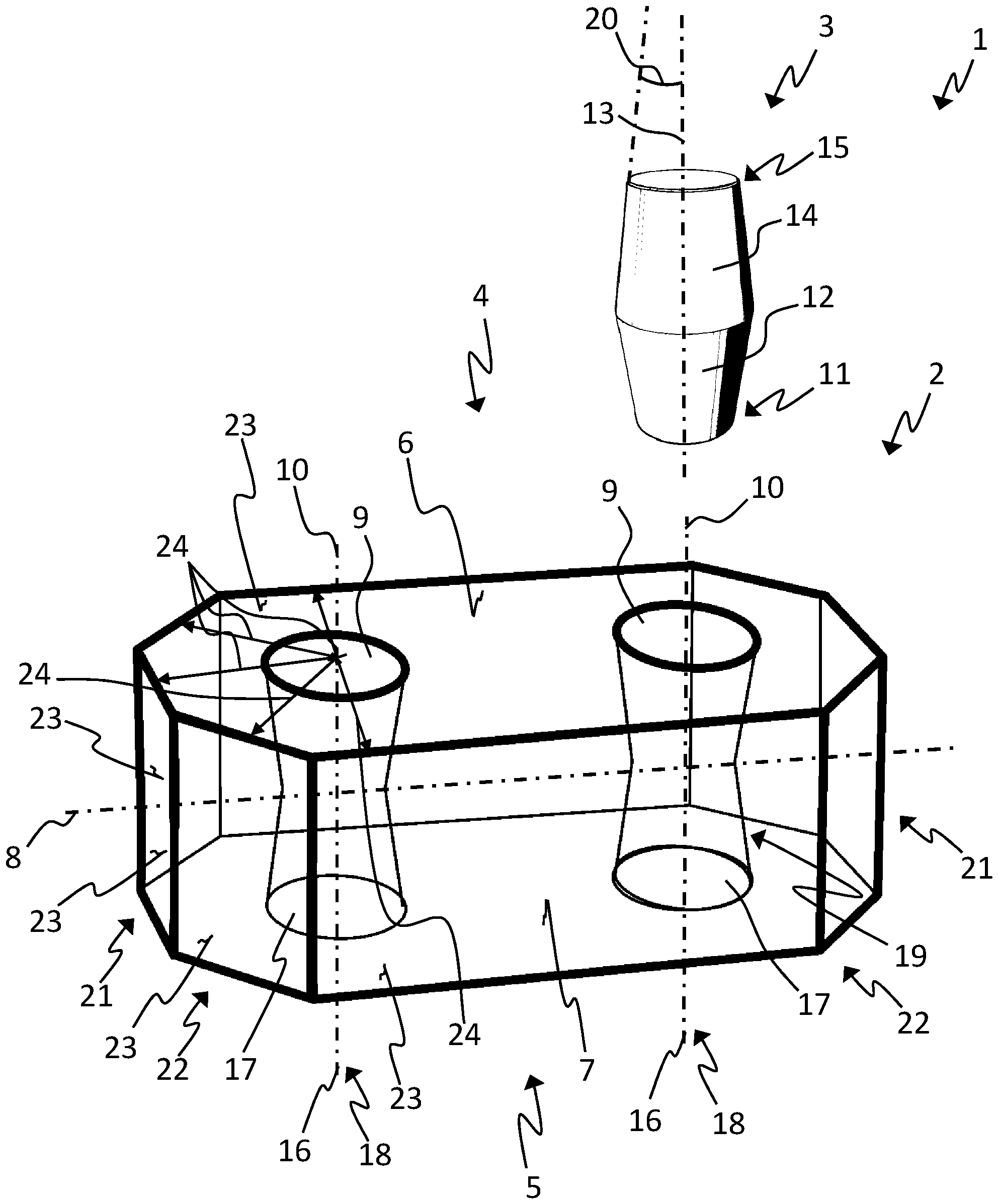
In
Der hier dargestellte Grundkörper
Der Grundkörper
In
In
In
Bezugszeichenliste LIST OF REFERENCE NUMBERS
- 1, 26, 27, 28, 29, 301, 26, 27, 28, 29, 30
- Bausteinbuilding block
- 22
- Grundkörperbody
- 33
- Verbindungselementconnecting element
- 44
- Kopfseitehead
- 55
- Fußseitefoot side
- 66
- Kopfflächehead face
- 77
- Fußflächefoot surface
- 88th
- Hauptachsemain axis
- 99
- Kopfausnehmunghead recess
- 1010
- KopfausnehmungsachseKopfausnehmungsachse
- 11,11
- 15 Distale Endbereiche15 distal end areas
- 1212
- Fußabschnittfoot section
- 1313
- VerbindungselementachseConnecting element axis
- 1414
- Kopfabschnittheader
- 1616
- FußausnehmungsachseFußausnehmungsachse
- 1717
- Fußausnehmungfoot recess
- 1818
- Ausnehmungsachsecavity axis
- 1919
- Verbindungsausnehmungconnecting recess
- 2020
- HalbkonuswinkelHalf cone angle
- 2121
- EndeThe End
- 2222
- GrundkörperendbereichGrundkörperendbereich
- 2323
- Seitenflächenfaces
- 2424
- Minimaler AbstandMinimum distance
- 2525
- Bausteinanordnungchip layout
- 3131
- Versetzungsabstandoffset distance
- 3232
- GewindestiftSet screw
- 3333
- Gewindeausnehmungthreaded recess
- 3434
- Abschlusselementtermination element
ZITATE ENTHALTEN IN DER BESCHREIBUNG QUOTES INCLUDE IN THE DESCRIPTION
Diese Liste der vom Anmelder aufgeführten Dokumente wurde automatisiert erzeugt und ist ausschließlich zur besseren Information des Lesers aufgenommen. Die Liste ist nicht Bestandteil der deutschen Patent- bzw. Gebrauchsmusteranmeldung. Das DPMA übernimmt keinerlei Haftung für etwaige Fehler oder Auslassungen.This list of the documents listed by the applicant has been generated automatically and is included solely for the better information of the reader. The list is not part of the German patent or utility model application. The DPMA assumes no liability for any errors or omissions.
Zitierte PatentliteraturCited patent literature
- US 3005282 A [0002]US 3005282 A [0002]
- GB 2471670 [0003]GB 2471670 [0003]
Claims (15)
Priority Applications (1)
| Application Number | Priority Date | Filing Date | Title |
|---|---|---|---|
| DE102019114532.5A DE102019114532A1 (en) | 2019-05-29 | 2019-05-29 | Block and block arrangement |
Applications Claiming Priority (1)
| Application Number | Priority Date | Filing Date | Title |
|---|---|---|---|
| DE102019114532.5A DE102019114532A1 (en) | 2019-05-29 | 2019-05-29 | Block and block arrangement |
Publications (1)
| Publication Number | Publication Date |
|---|---|
| DE102019114532A1 true DE102019114532A1 (en) | 2019-08-14 |
Family
ID=67399726
Family Applications (1)
| Application Number | Title | Priority Date | Filing Date |
|---|---|---|---|
| DE102019114532.5A Ceased DE102019114532A1 (en) | 2019-05-29 | 2019-05-29 | Block and block arrangement |
Country Status (1)
| Country | Link |
|---|---|
| DE (1) | DE102019114532A1 (en) |
Cited By (1)
| Publication number | Priority date | Publication date | Assignee | Title |
|---|---|---|---|---|
| NL2029893B1 (en) * | 2021-11-24 | 2023-06-15 | Eve Blox Beheer B V | Modular toy construction system and method of assembling such toy construction system |
Citations (2)
| Publication number | Priority date | Publication date | Assignee | Title |
|---|---|---|---|---|
| US3005282A (en) | 1958-01-28 | 1961-10-24 | Interlego Ag | Toy building brick |
| GB2471670A (en) | 2009-07-04 | 2011-01-12 | Stanley Canning | Interlocking toy building blocks |
-
2019
- 2019-05-29 DE DE102019114532.5A patent/DE102019114532A1/en not_active Ceased
Patent Citations (2)
| Publication number | Priority date | Publication date | Assignee | Title |
|---|---|---|---|---|
| US3005282A (en) | 1958-01-28 | 1961-10-24 | Interlego Ag | Toy building brick |
| GB2471670A (en) | 2009-07-04 | 2011-01-12 | Stanley Canning | Interlocking toy building blocks |
Cited By (1)
| Publication number | Priority date | Publication date | Assignee | Title |
|---|---|---|---|---|
| NL2029893B1 (en) * | 2021-11-24 | 2023-06-15 | Eve Blox Beheer B V | Modular toy construction system and method of assembling such toy construction system |
Similar Documents
| Publication | Publication Date | Title |
|---|---|---|
| DE3114693A1 (en) | DESIGN TOY | |
| DE1750969B1 (en) | CONNECTING DEVICE FOR CONNECTING TUBE-SHAPED PARTS | |
| DE1478289A1 (en) | Kit, especially for playing | |
| DE1988924U (en) | COMPONENT, IN PARTICULAR FOR BOAT GRATING, FLOATING BRIDGES, FORMWORK AND THE LIKE. | |
| WO2007049097A2 (en) | Linking system for producing a link between building elements | |
| DE102019114532A1 (en) | Block and block arrangement | |
| DE2646007A1 (en) | ANCHORING DOWEL | |
| DE69530226T2 (en) | INSULATING COMPONENT OR BLOCK. | |
| DE2822946A1 (en) | FASTENING DEVICE, IN PARTICULAR FOR CONNECTING PIPE END FOR FRAME | |
| DE9319646U1 (en) | Brick system | |
| DE19953904C1 (en) | Kit for the erection of garden structures has a base plate on a ground anchor supporting a mounting tube section to take an inserted structure tube and be locked in place | |
| DE19531658B4 (en) | Support device for a cableway | |
| DE1076007B (en) | Component for building toys | |
| DE10325407B3 (en) | Building block system used for constructing furniture, facades, and buildings or as a wall element or toy comprises a volume body, preferably a cube, composed of partial elements, preferably by form-locking joints | |
| DE1805769A1 (en) | Circuit building block support elements | |
| DE2241787A1 (en) | PILE CONNECTION | |
| DE3142934A1 (en) | Bar element composed of a plurality of individual bars for building systems | |
| DE102006024070A1 (en) | Wire frame with connector e.g. for connecting single wire frame panels, linked adjacent to each other and have wire mesh panels with lattice formed with crossing points of rods firmly linked together which together form grid box | |
| AT370475B (en) | COMPONENT AND CONNECTIONS OF SUCH COMPONENTS | |
| DE2111971B2 (en) | Component made of plastic for the production of flat or three-dimensional structures | |
| DE202008010523U1 (en) | Building blocks for T-shaped wall sections | |
| DE2101483A1 (en) | Plug-in profiles for roof construction | |
| DE9312416U1 (en) | Building element made of expanded materials | |
| DE1951076A1 (en) | Duebel device for connecting boards | |
| DE102004012235B4 (en) | Dismountable house models |
Legal Events
| Date | Code | Title | Description |
|---|---|---|---|
| R012 | Request for examination validly filed | ||
| R082 | Change of representative |
Representative=s name: HABERMANN INTELLECTUAL PROPERTY PARTNERSCHAFT , DE |
|
| R230 | Request for early publication | ||
| R002 | Refusal decision in examination/registration proceedings | ||
| R003 | Refusal decision now final |