DE102018106295B4 - Method for producing an assembly for an operating element - Google Patents
Method for producing an assembly for an operating element Download PDFInfo
- Publication number
- DE102018106295B4 DE102018106295B4 DE102018106295.8A DE102018106295A DE102018106295B4 DE 102018106295 B4 DE102018106295 B4 DE 102018106295B4 DE 102018106295 A DE102018106295 A DE 102018106295A DE 102018106295 B4 DE102018106295 B4 DE 102018106295B4
- Authority
- DE
- Germany
- Prior art keywords
- spring element
- plastic melt
- plastic
- injection mold
- procedure according
- Prior art date
- Legal status (The legal status is an assumption and is not a legal conclusion. Google has not performed a legal analysis and makes no representation as to the accuracy of the status listed.)
- Active
Links
- 238000004519 manufacturing process Methods 0.000 title claims abstract description 23
- 239000004033 plastic Substances 0.000 claims abstract description 93
- 238000002347 injection Methods 0.000 claims abstract description 64
- 239000007924 injection Substances 0.000 claims abstract description 64
- 238000000034 method Methods 0.000 claims description 26
- 238000001746 injection moulding Methods 0.000 claims description 13
- 229910000639 Spring steel Inorganic materials 0.000 claims description 4
- 238000001125 extrusion Methods 0.000 claims description 4
- 239000000463 material Substances 0.000 claims description 2
- 238000009434 installation Methods 0.000 description 5
- 238000005452 bending Methods 0.000 description 3
- 238000001514 detection method Methods 0.000 description 3
- 238000010276 construction Methods 0.000 description 2
- 230000000694 effects Effects 0.000 description 2
- 239000011159 matrix material Substances 0.000 description 2
- 239000002184 metal Substances 0.000 description 2
- 229920000642 polymer Polymers 0.000 description 2
- 238000007493 shaping process Methods 0.000 description 2
- 238000005538 encapsulation Methods 0.000 description 1
- 238000005516 engineering process Methods 0.000 description 1
- 238000011156 evaluation Methods 0.000 description 1
- 239000002991 molded plastic Substances 0.000 description 1
- 238000000465 moulding Methods 0.000 description 1
- 230000010355 oscillation Effects 0.000 description 1
- 238000004080 punching Methods 0.000 description 1
- 238000007789 sealing Methods 0.000 description 1
- 239000007787 solid Substances 0.000 description 1
- 230000006641 stabilisation Effects 0.000 description 1
- 238000011105 stabilization Methods 0.000 description 1
Images


Classifications
-
- B—PERFORMING OPERATIONS; TRANSPORTING
- B29—WORKING OF PLASTICS; WORKING OF SUBSTANCES IN A PLASTIC STATE IN GENERAL
- B29C—SHAPING OR JOINING OF PLASTICS; SHAPING OF MATERIAL IN A PLASTIC STATE, NOT OTHERWISE PROVIDED FOR; AFTER-TREATMENT OF THE SHAPED PRODUCTS, e.g. REPAIRING
- B29C45/00—Injection moulding, i.e. forcing the required volume of moulding material through a nozzle into a closed mould; Apparatus therefor
- B29C45/16—Making multilayered or multicoloured articles
- B29C45/1615—The materials being injected at different moulding stations
-
- B—PERFORMING OPERATIONS; TRANSPORTING
- B29—WORKING OF PLASTICS; WORKING OF SUBSTANCES IN A PLASTIC STATE IN GENERAL
- B29L—INDEXING SCHEME ASSOCIATED WITH SUBCLASS B29C, RELATING TO PARTICULAR ARTICLES
- B29L2031/00—Other particular articles
- B29L2031/46—Knobs or handles, push-buttons, grips
Landscapes
- Engineering & Computer Science (AREA)
- Manufacturing & Machinery (AREA)
- Mechanical Engineering (AREA)
- Injection Moulding Of Plastics Or The Like (AREA)
- Moulds For Moulding Plastics Or The Like (AREA)
Abstract
Verfahren zum Herstellen einer Baugruppe (1) für ein Bedienelement aufweisend eine haptische Rückmeldung bei einer Betätigung durch einen Benutzer, dadurch gekennzeichnet, dass zur Herstellung der Baugruppe (1)- zunächst ein Vorspritzling (7, 7') gebildet wird, indem ein Federelement (3, 3') in ein erstes Spritzgießwerkzeug (10) eingelegt wird und zumindest ein erstes Ende (4) des Federelements (3, 3'), welches zur Verbindung mit einem Trägerelement (2) vorgesehen ist, mit einer ersten Kunststoffschmelze (9) umspritzt wird, wobei der Vorspritzling (7, 7') vorzugsweise nach dem Aushärten der ersten Kunststoffschmelze (9) weiterverarbeitet wird, und- in einem weiteren Schritt der Vorspritzling (7, 7') in ein zweites Spritzgießwerkzeug (17) eingelegt wird und danach das mit der ersten Kunststoffschmelze (9) umspritzte erste Ende (4) des Federelements (3, 3') mit einer zweiten Kunststoffschmelze (21) umspritzt wird, wobei spätestens nach einem Aushärten der zweiten Kunststoffschmelze (21) das erste mit Kunststoffschmelze (9) umspritzte Ende (4) des Federelements (3, 3') mit der zweiten Kunststoffschmelze (21) stoffschlüssig verbunden ist, wobei die zweite, insbesondere ausgehärtete Kunststoffschmelze (21) zumindest teilweise als Trägerelement (2) ausgebildet ist, wobei die Baugruppe (1) das zumindest teilweise von Kunststoff umspritzte Federelement (3, 3') und das Trägerelement (2) umfasst, die miteinander stoffschlüssig verbunden sind.Method for producing an assembly (1) for an operating element, comprising a haptic feedback when actuated by a user, characterized in that for the manufacture of the assembly (1) - first a pre-molded part (7, 7 ') is formed by a spring element ( 3, 3 ') is inserted into a first injection mold (10) and at least a first end (4) of the spring element (3, 3'), which is provided for connection to a carrier element (2), with a first plastic melt (9) is overmolded, the pre-molded part (7, 7 ') preferably being further processed after the first plastic melt (9) has hardened, and - in a further step, the pre-molded part (7, 7') is inserted into a second injection mold (17) and then the first end (4) of the spring element (3, 3 ') overmolded with the first plastic melt (9) is overmolded with a second plastic melt (21), at the latest after the second plastic melt has hardened elze (21) the first end (4) of the spring element (3, 3 ') overmolded with plastic melt (9) is integrally connected to the second plastic melt (21), the second, in particular hardened plastic melt (21) at least partially as a carrier element ( 2), the assembly (1) comprising the spring element (3, 3 ') at least partially overmolded with plastic and the carrier element (2), which are integrally connected to one another.
Description
Die Erfindung betrifft ein Verfahren zum Herstellen einer Baugruppe für ein Bedienelement aufweisend eine haptische Rückmeldung bei einer Betätigung durch einen Benutzer.The invention relates to a method for producing an assembly for an operating element having haptic feedback when actuated by a user.
Aus dem Stand der Technik ist ein mit einem haptischen Feedback versehenes Bedienelement mit einem Trägerelement bekannt. Das Trägerelement und das Bedienelement werden mit Hilfe von Federelementen mittelbar oder unmittelbar miteinander verbunden. Diese Federelemente werden mit Schrauben an das Trägerelement angeschraubt und bilden gemeinsam mit dem Trägerelement eine Baugruppe. Nachteilig ist jedoch, dass ein zusätzlicher Arbeitsschritt notwendig ist, nämlich das Anschrauben des Federelements an das Trägerelement. Des Weiteren sind die Schrauben zusätzliche Bauteile, die die Konstruktion unnötiger Weise teurer machen. Ferner muss der Bauraum am Bedienelement und/oder Trägerelement, welcher für die Federelemente vorgesehen ist, mit relativ großen Einbautoleranzen versehen werden, weil sich beispielsweise die als dünnwandige Blattfedern ausgebildeten Federelemente beim Festziehen der Schrauben unelastisch verformen können.A control element with a carrier element that is provided with haptic feedback is known from the prior art. The support element and the control element are connected to one another indirectly or directly with the aid of spring elements. These spring elements are screwed onto the carrier element with screws and form an assembly together with the carrier element. However, it is disadvantageous that an additional step is necessary, namely screwing the spring element onto the carrier element. Furthermore, the screws are additional components that make the construction unnecessarily expensive. Furthermore, the installation space on the control element and / or support element which is provided for the spring elements must be provided with relatively large installation tolerances because, for example, the spring elements designed as thin-walled leaf springs can deform inelastically when the screws are tightened.
Aus diesem Grund ist man im Stand der Technik dazu übergegangen, die Federelemente zu umspritzen. Das Umspritzen von Bauelementen, insbesondere Federelementen ist hinlänglich bekannt. Allerdings treten beim Umspritzen von dünnwandigen Bauelementen, insbesondere Blattfedern, die beispielsweise als Stanzteile und Biegeteile ausgebildet sind, Probleme auf.For this reason, the prior art has started to overmold the spring elements. The encapsulation of components, in particular spring elements, is well known. However, problems occur when encapsulating thin-walled components, in particular leaf springs, which are designed, for example, as stamped parts and bent parts.
Die Blattfedern werden direkt in ein Spritzgießwerkzeug, insbesondere in eine Formhälfte oder Spritzgießform eingelegt und mit Kunststoffschmelze umspritzt, wobei die Kunststoffschmelze nach dem Aushärten als Trägerelement ausgebildet ist. Allein schon das Positionieren und Fixieren des dünnwandigen Federelements in dem Spritzgießwerkzeug führt zu Problemen. Dabei ist die Hauptentformungsrichtung des Werkzeugs senkrecht zurThe leaf springs are placed directly in an injection mold, in particular in a mold half or injection mold, and overmolded with plastic melt, the plastic melt being designed as a carrier element after curing. The positioning and fixing of the thin-walled spring element in the injection mold alone leads to problems. The main demoulding direction of the tool is perpendicular to
Haupterstreckungsebene des Trägers, also parallel zur Haupterstreckung des Federelements. Daher muss das Federelement mit Hilfe eines Schiebers gehalten und stabilisiert werden. Die Haltekraft des Schiebers ist nur ein Bruchteil der Schließkraft des Werkzeugs, sodass beim Spritzgießvorgangs auf das freie Ende des Federelements ein hoher Druck wirkt. Dies führt zu dem Nachteil, dass die Positionierung und Stabilisierung mit Hilfe des Schiebers zu erhöhten Toleranzen führt, insbesondere wenn das sehr dünnwandige Federelement beispielsweise eine Dicke von 0,1-0,2 mm aufweist.Main extension plane of the carrier, that is parallel to the main extension of the spring element. Therefore, the spring element must be held and stabilized with the help of a slide. The holding force of the slide is only a fraction of the closing force of the tool, so that a high pressure acts on the free end of the spring element during the injection molding process. This leads to the disadvantage that the positioning and stabilization with the aid of the slide leads to increased tolerances, in particular if the very thin-walled spring element has a thickness of 0.1-0.2 mm, for example.
Ferner führt der hohe Druck beim Spritzgießvorgang dazu, dass das Federelement an den Stellen, wo keine Unterstützung durch den Schieber vorliegt eine plastische Verformung erfahren kann. Auch besteht die Gefahr, dass das dünnwandige Federelement in der Kunststoffschmelze mit dem Aushärten dieser Undefiniert verspannt wird, und somit auch die Form des Federelements negativ beeinflusst wird.Furthermore, the high pressure during the injection molding process means that the spring element can undergo plastic deformation at the points where there is no support from the slide. There is also the danger that the thin-walled spring element in the plastic melt will be braced as it is undefined, and thus the shape of the spring element will also be negatively influenced.
Des Weiteren kann das freie Ende des Federelements mit dem Bedienelement, insbesondere mit einem aus Kunststoff ausgebildeten Gehäuse des Bedienelements verbunden, insbesondere verschnappt werden. Bei starken Vibrationen parallel zur Haupterstreckung des Federelements kann es aufgrund der geringen Dicke des Federelements zu Beschädigungen im Bereich der Verbindung mit dem Gehäuse kommen. Dabei schneidet das scharfe und dünnwandige Federelement wie ein Messer in den Kunststoff des Gehäuses ein und beschädigt dieses.Furthermore, the free end of the spring element can be connected, in particular snapped, to the control element, in particular to a plastic housing of the control element. In the case of strong vibrations parallel to the main extent of the spring element, the small thickness of the spring element can cause damage in the area of the connection to the housing. The sharp and thin-walled spring element cuts into the plastic of the housing like a knife and damages it.
Beim Umspritzen von dünnwandigen Bauteilen, wie beispielsweise Blattfedern besteht daher die Gefahr, dass die Federelemente während des Umspritzens deformiert werden und /oder in dem Bedienelement nicht richtig positioniert werden können. Daher werden die Bauräume in dem Bedienelement, welche zur Anordnung der Federelemente vorgesehen sind, mit höheren Toleranzen versehen. Wenn die umspritzten Federelemente nun in die entsprechenden Bauräume des Bedienelements eingesetzt werden, kann es vorkommen, dass die Federelemente teilweise locker bzw. schwimmend in den Bauräumen gelagert sind. Dies wirkt sich dann besonders negativ auf die haptischen Eigenschaften des Bedienelements aus, welches bei einer Berührung von einem Benutzer in Schwingung versetzt wird.When overmoulding thin-walled components, such as leaf springs, there is therefore a risk that the spring elements will be deformed during the overmolding and / or cannot be correctly positioned in the operating element. Therefore, the installation spaces in the control element, which are provided for the arrangement of the spring elements, are provided with higher tolerances. If the overmolded spring elements are now inserted into the corresponding installation spaces of the control element, it can happen that the spring elements are partially loosely or floatingly supported in the installation spaces. This then has a particularly negative effect on the haptic properties of the control element, which is set in motion by a user when touched.
Formgebende Verfahren zur Herstellung einer Baugruppe, bei denen jeweils eine erste Komponente in dem formgebenden Verfahren umformt wird, sind aus der
Daher ist es die Aufgabe der Erfindung, ein Verfahren zum Herstellen einer Baugruppe für ein Bedienelement bereitzustellen, welches kostengünstig und einfach durchzuführen ist und die haptischen Eigenschaften des Bedienelements verbessert.It is therefore the object of the invention to provide a method for producing an assembly for an operating element which is inexpensive and simple to carry out and which improves the haptic properties of the operating element.
Die Aufgabe wird gelöst durch ein Verfahren zum Herstellen einer Baugruppe mit den Merkmalen des Patentanspruchs 1. Dabei ist vorgesehen, dass zur Herstellung der Baugruppe zunächst ein Vorspritzling gebildet wird, indem ein Federelement in ein erstes Spritzgießwerkzeug eingelegt wird und zumindest ein erstes Ende des Federelements, welches zur Verbindung mit einem Trägerelement vorgesehen ist, mit einer ersten Kunststoffschmelze umspritzt wird, wobei der Vorspritzling vorzugsweise nach dem Aushärten der ersten Kunststoffschmelze weiterverarbeitet wird, und in einem weiteren Schritt der Vorspritzling in ein zweites Spritzgießwerkzeug eingelegt wird und danach das mit der ersten Kunststoffschmelze umspritzte erste Ende des Federelements mit einer zweiten Kunststoffschmelze umspritzt wird, wobei spätestens nach einem Aushärten der zweiten Kunststoffschmelze das erste mit Kunststoffschmelze umspritzte Ende des Federelements mit der zweiten Kunststoffschmelze stoffschlüssig verbunden ist, wobei die zweite, insbesondere ausgehärtete Kunststoffschmelze zumindest teilweise als Trägerelement ausgebildet ist, wobei die Baugruppe das zumindest teilweise von Kunststoff umspritzte Federelement und das Trägerelement umfasst, die miteinander stoffschlüssig verbunden sind.The object is achieved by a method for producing an assembly having the features of patent claim 1. It is provided that for the manufacture of the assembly a preform is first formed by inserting a spring element into a first injection mold and at least a first end of the spring element, which is provided for connection to a carrier element, extrusion-coated with a first plastic melt is, the pre-molded part is preferably processed further after the curing of the first plastic melt, and in a further step the pre-molded part is placed in a second injection mold and then the first end of the spring element overmolded with the first plastic melt is overmolded with a second plastic melt, at the latest after after the second plastic melt has hardened, the first end of the spring element overmolded with plastic melt is integrally connected to the second plastic melt, the second, in particular hardened plastic melt being at least partially designed as a carrier element, the assembly comprising the at least partially overmolded plastic spring element and the carrier element, that are cohesively connected.
Das Bedienelement, insbesondere für Kraftfahrzeuge, kann als berührempfindliches Eingabeteil ausgebildet sein. Der Begriff „berührempfindliches Eingabeteil“ ist weit auszulegen. Dabei handelt es sich im Allgemeinen um ein Teil des Eingabegeräts, das eine dem Bediener zugewandte Eingabefläche definiert, auf der eine Berührung durch ein Eingabeorgan oder einen Finger eines Bedieners durch eine Sensorik detektiert wird, bevorzugt ortsauflösend detektiert wird. Bevorzugt handelt es sich bei dem berührempfindlichen Eingabeteil um ein Touchpad, d.h. ein anzeigeloses Eingabeteil mit ortsauflösender Detektion einer Berührung auf einer zum Eingabeteil gehörigen Eingabefläche oder ein Touchscreen, d.h. ein Eingabeteil mit ortsauflösender Detektion einer Berührung auf einer zum Eingabeteil gehörigen Eingabefläche, wobei im letzteren Fall der Eingabefläche ferner eine elektronische Anzeige, insbesondere eine elektronische Pixelmatrixanzeige zugeordnet ist.The control element, in particular for motor vehicles, can be designed as a touch-sensitive input part. The term “touch-sensitive input part” should be interpreted broadly. In general, this is a part of the input device that defines an input surface facing the operator, on which touch by an input element or an operator's finger is detected by a sensor system, preferably detected in a location-resolving manner. The touch-sensitive input part is preferably a touchpad, i.e. a displayless input part with spatially resolving detection of a touch on an input surface belonging to the input part or a touchscreen, i.e. an input part with spatially resolving detection of a touch on an input surface belonging to the input part, wherein in the latter case the input surface is further assigned an electronic display, in particular an electronic pixel matrix display.
Beispielsweise sind der Eingabefläche ein oder mehrere Sensoren zur Detektion einer Berührung und/oder einer Druckkraft auf der Eingabefläche zugeordnet. Beispielsweise handelt es sich um mehrere in einer Matrix angeordnete Elektroden und eine zugehörige Auswerteinheit zur ortsauflösenden Berührungsdetektion und/oder einen oder mehrere Kraftsensoren zur Detektion der durch die Betätigung bewirkten Druckkraft, wie einen oder mehrere kapazitive Kraftsensoren.For example, one or more sensors for detecting a touch and / or a pressure force on the input surface are assigned to the input surface. For example, there are several electrodes arranged in a matrix and an associated evaluation unit for spatially resolving contact detection and / or one or more force sensors for detecting the pressure force caused by the actuation, such as one or more capacitive force sensors.
Bei dem Federelement kann es sich beispielsweise um eine Blattfeder handeln, welche mit Hilfe eines Stanzwerkzeugs hergestellt wurde. Das Federelement ist dabei vorzugsweise aus einem Metall ausgebildet, welches eine Dicke von beispielsweise 0,1-0,25 mm aufweist.The spring element can be a leaf spring, for example, which was produced with the aid of a punching tool. The spring element is preferably made of a metal which has a thickness of 0.1-0.25 mm, for example.
Mit Hilfe des erfindungsgemäßen Verfahrens kann in vorteilhafter Weise sichergestellt werden, dass das umspritzt Federelement positionsgenau und ohne eine Verbiegung in das zweite Spritzgießwerkzeug eingelegt werden kann. Durch den ersten Spritzgießvorgang wird das erste Ende des Federelements verstärkt, sodass bei dem nachfolgenden zweiten Spritzgießvorgang ein Verbiegen des Federelements ausgeschlossen ist. Ein zusätzlicher vorteilhafter Effekt entsteht dadurch, dass aufgrund der erhöhten Dicke des ersten Endes des Federelements, welches durch den ersten Spritzgießvorgang mittels der ersten Kunststoffschmelze hergestellt wurde, die genauere Positionierung im zweiten Spritzgießwerkzeug stattfinden kann. Des Weiteren kann sowohl bei dem ersten Spritzgießwerkzeug, als auch bei dem zweiten Spritzgießwerkzeug auf einen Schieber zum Halten und Positionieren des Federelements verzichtet werden, wodurch die Herstellungskosten der Spritzgießwerkzeuge verringert werden. Durch das erfindungsgemäße Verfahren kann weiter gewährleistet werden, dass weder beim ersten Spritzgießvorgang, noch beim zweiten Spritzgießvorgang das Federelement deformiert, verbogen und verspannt wird. Durch die Baugruppe, welche durch das erfindungsgemäße Verfahren hergestellt wird, ist somit in vorteilhafter Weise dafür gesorgt, dass die haptischen Eigenschaften des Bedienelements verbessert werden. Ferner werden die Konstruktionskosten zur Herstellung der Baugruppe, insbesondere des Bedienelements verringert, weil auf zusätzlich Arbeitsschritte, wie beispielsweise ein Verschrauben des Federelements verzichtet werden kann.With the aid of the method according to the invention, it can be ensured in an advantageous manner that the extrusion-coated spring element can be inserted in the exact position and without bending into the second injection mold. The first injection molding process reinforces the first end of the spring element, so that bending of the spring element is ruled out in the subsequent second injection molding process. An additional advantageous effect arises from the fact that, due to the increased thickness of the first end of the spring element, which was produced by the first injection molding process by means of the first plastic melt, the more precise positioning can take place in the second injection mold. Furthermore, a slide for holding and positioning the spring element can be dispensed with both in the first injection mold and in the second injection mold, thereby reducing the production costs of the injection molds. The method according to the invention can furthermore ensure that the spring element is not deformed, bent and clamped neither in the first injection molding process nor in the second injection molding process. The assembly, which is produced by the method according to the invention, thus advantageously ensures that the haptic properties of the control element are improved. Furthermore, the construction costs for producing the assembly, in particular the control element, are reduced because additional work steps, such as screwing the spring element, can be dispensed with.
Nach einer bevorzugten Ausführung des erfindungsgemäßen Verfahrens ist vorgesehen, dass das erste Ende des Federelements und/oder das zweite Ende des Federelements zumindest eine Ausnehmung aufweist, durch welche die erste Kunststoffschmelze bei der Herstellung des Vorspritzlings hindurchfließt bzw. hindurchströmt. Diese Maßnahme dient in vorteilhafter Weise dazu, um beim Umspritzens des Federelements eine formschlüssige Verbindung der Kunststoffschmelze mit dem Federelement mit Hinterschnitten zu gewährleisten. Dabei können die Ausnehmungen beispielsweise als runde oder kreisförmige Löcher ausgebildet sein. Diese Ausnehmungen können sowohl am ersten Ende des Federelements, als auch am zweiten Ende des Federelements angeordnet sein.According to a preferred embodiment of the method according to the invention, it is provided that the first end of the spring element and / or the second end of the spring element has at least one recess through which the first plastic melt flows or flows during the production of the preform. This measure advantageously serves to ensure a positive connection of the plastic melt to the spring element with undercuts when the spring element is molded around. The recesses can be designed, for example, as round or circular holes. These recesses can be arranged both at the first end of the spring element and at the second end of the spring element.
Nach einer weiteren bevorzugten Ausführung des erfindungsgemäßen Verfahrens ist vorgesehen, dass ein zweites Ende des Federelements, welches vorzugsweise diametral gegenüber dem ersten Ende angeordnet ist, ebenfalls mit der ersten Kunststoffschmelze in dem ersten Spritzgießwerkzeug umspritzt wird. Es ist sinnvoll, die Ausnehmungen am Federelement dort anzuordnen, wo das Federelement mit Kunststoffschmelze umspritzt werden soll, um eine formschlüssige Verbindung zwischen dem Federelement und der, insbesondere ausgehärteten Kunststoffschmelze bereitzustellen. Die vorzugsweise an den beiden Enden ausgehärtete erste Kunststoffschmelze kann eine Dicke von beispielsweise 1,5 mm aufweisen. Somit ist die Führung und Positionierung des Vorspritzlings in dem zweiten Spritzgießwerkzeug einfacher durchzuführen, weil in dem zweiten Spritzgießwerkzeug auf einen schmalen Schlitz zur Positionierung des dünnwandigen Federelements verzichtet werden kann. Aufgrund der mit der ersten Kunststoffschmelze aufgedickten Enden des Federelements kann der Schlitz des zweiten Spritzgießwerkzeugs zur Positionierung des Vorspritzlings vergrößert werden, wodurch die Montage des Vorspritzlings in dem zweiten Spritzgießwerkzeug erleichtert wird.According to a further preferred embodiment of the method according to the invention, it is provided that a second end of the spring element, which is preferably arranged diametrically opposite the first end, is also extrusion-coated with the first plastic melt in the first injection mold. It makes sense to arrange the recesses on the spring element where the spring element is to be encapsulated with plastic melt in order to provide a positive connection between the spring element and the, in particular hardened, plastic melt. The one that is preferably hardened at both ends first plastic melt can have a thickness of, for example, 1.5 mm. The guiding and positioning of the pre-molded part in the second injection molding tool is thus easier to carry out because a narrow slot for positioning the thin-walled spring element can be dispensed with in the second injection molding tool. Due to the ends of the spring element thickened with the first plastic melt, the slot of the second injection molding tool for positioning the pre-molded part can be enlarged, whereby the assembly of the pre-molded part in the second injection molding tool is facilitated.
Die Weiterverarbeitung des Vorspritzlings kann vereinfacht werden, wenn nach einer bevorzugten Ausführung des erfindungsgemäßen Verfahrens vorgesehen ist, dass spätestens nach dem Aushärten der Kunststoffschmelze des Vorspritzlings das erste Ende des Federelements einen ersten Kunststoffabschnitt aufweist und das zweite Ende des Federelements einen zweiten Kunststoffabschnitt aufweist.The further processing of the pre-molded part can be simplified if, according to a preferred embodiment of the method according to the invention, it is provided that at the latest after the plastic melt of the pre-molded part has hardened, the first end of the spring element has a first plastic section and the second end of the spring element has a second plastic section.
Nach einer weiteren bevorzugten Ausführung des Verfahrens kann vorgesehen sein, dass der zweite Kunststoffabschnitt einen Verbindungsabschnitt, vorzugsweise eine Aussparung oder Kerbe, aufweist, der durch das erste Spritzgießwerkzeug erzeugt wurde und zur Verbindung mit einem Rastelement, insbesondere einen Schnapphaken dient. Mit Hilfe des aus Kunststoff ausgebildeten Verbindungsabschnitts kann ein Rastelement, welches vorzugsweise am Bedienelement oder an einem dem Bedienelement zugeordneten Gehäuse angeordnet ist, sicher mit dem Federelement verbunden werden und gleichzeitig werden die haptischen Eigenschaften des Bedienelements verbessert. Das Federelement, welches den mit Kunststoff ausgebildeten Verbindungsabschnitt aufweist, sorgt in vorteilhafter Weise dafür, dass eine Beschädigung des Bedienelements und/oder des Gehäuses des Bedienelements durch das scharfkantige Federelement auch bei Vibrationen des Federelements, die durch eine Betätigung des Bedienelements hervorgerufen werden, in horizontaler Richtung ausgeschlossen ist. Es werden sozusagen die aus Metall ausgebildeten messerscharfen Kanten des Federelements durch den aus Kunststoff ausgebildeten Verbindungsabschnitt abgerundet und/oder entschärft.According to a further preferred embodiment of the method, it can be provided that the second plastic section has a connecting section, preferably a recess or notch, which was produced by the first injection mold and is used for connection to a latching element, in particular a snap hook. With the aid of the connecting section made of plastic, a latching element, which is preferably arranged on the control element or on a housing assigned to the control element, can be securely connected to the spring element and at the same time the haptic properties of the control element are improved. The spring element, which has the connecting section formed with plastic, advantageously ensures that damage to the operating element and / or the housing of the operating element by the sharp-edged spring element also occurs horizontally in the event of vibrations of the spring element that are caused by actuation of the operating element Direction is excluded. The razor-sharp edges of the spring element made of metal are rounded off and / or defused by the connecting section made of plastic.
Die Herstellung der Baugruppe kann durch das erfindungsgemäße Verfahren vereinfacht werden und prozesssicherer gestaltet werden, wenn das erste Spritzgießwerkzeug mindestens zwei Formhälften aufweist, in welches das Federelement zur Herstellung des Vorspritzlings eingelegt wird.The production of the assembly can be simplified by the method according to the invention and can be made more reliable if the first injection molding tool has at least two mold halves into which the spring element for producing the preform is inserted.
Die Herstellung der Braugruppe kann weiter vereinfacht werden, wenn das zweite Spritzgießwerkzeug mindestens zwei Formhälften aufweist, wobei in eine Formhälfte der Vorspritzling angeordnet wird. Dabei kann der Vorspritzling sicher und einfach in dem zweiten Spritzgießwerkzeug positioniert werden.The production of the brewing group can be further simplified if the second injection mold has at least two mold halves, the pre-molded part being arranged in one mold half. The pre-molded part can be positioned safely and easily in the second injection mold.
Nach einer weiteren bevorzugten Ausführung des erfindungsgemäßen Verfahrens kann vorgesehen sein, dass die beiden Formhälften des zweiten Spritzgießwerkzeugs einen Durchflusskanal bilden, durch welchen die zweite Kunststoffschmelze hindurchströmt und/oder hineinströmt. Der Durchflusskanal dient dabei zur Herstellung des Trägerelements und gleichzeitig wird beim Hindurchströmen der zweiten Kunststoffschmelze der Vorspritzling mit dem Trägerelement stoffschlüssig verbunden. Somit wird gleichzeitig das Trägerelement formtechnisch hergestellt und eine Verbindung mit dem Vorspritzlings, insbesondere mit dem Federelement sichergestellt.According to a further preferred embodiment of the method according to the invention, it can be provided that the two mold halves of the second injection mold form a flow channel through which the second plastic melt flows and / or flows into. The flow channel serves to produce the carrier element and, at the same time, the preform is connected to the carrier element in a materially integral manner as the second plastic melt flows through it. Thus, the carrier element is simultaneously produced in terms of molding technology and a connection with the pre-molded part, in particular with the spring element, is ensured.
Damit der Bereich zwischen dem ersten Ende und dem zweiten Ende des Federelements frei von der zweiten Kunststoffschmelze bleibt und somit das Federelement seine elastischen Eigenschaften weiter beibehält, kann vorgesehen sein, dass die zur Anordnung des Vorspritzlings ausgebildete Formhälfte des zweiten Spritzgießwerkzeugs einen Kanal aufweist, in welchen der Vorspritzling eingelegt wird, wobei der Vorspritzling den Kanal, insbesondere einen mittleren Kanalabschnitt des Kanals, gegenüber dem Durchflusskanal abdichtet.So that the area between the first end and the second end of the spring element remains free of the second plastic melt and thus the spring element continues to retain its elastic properties, it can be provided that the mold half of the second injection mold, which is designed to arrange the preform, has a channel in which the pre-molded part is inserted, the pre-molded part sealing the channel, in particular a central channel section of the channel, from the flow channel.
Die Komplexität des ersten Spritzgießwerkzeugs kann verringert werden, wenn das Federelement horizontal und/oder liegend in das erste Spritzgießwerkzeug eingelegt wird, so dass eine Breitseite des Federelements im Wesentlichen parallel zu den Oberflächen der Formhälften des ersten Spritzgießwerkzeugs angeordnet ist. Folglich kann bei dem ersten Spritzgießwerkzeug auch auf einen Schieber zum Halten, Positionieren und Fixieren des dünnwandigen Federelements verzichtet werden. Da das Federelement liegend im ersten Spritzgießwerkzeug angeordnet ist, ist somit eine Verbiegung des dünnwandigen Federelements ausgeschlossen.The complexity of the first injection mold can be reduced if the spring element is inserted horizontally and / or lying horizontally in the first injection mold, so that a broad side of the spring element is arranged essentially parallel to the surfaces of the mold halves of the first injection mold. Consequently, a slide for holding, positioning and fixing the thin-walled spring element can also be dispensed with in the first injection mold. Since the spring element is arranged horizontally in the first injection mold, bending of the thin-walled spring element is thus ruled out.
Eine schnellere Herstellung des Vorspritzlings kann gewährleistet werden, wenn das erste Spritzgießwerkzeug einen ersten Einspritzkanal zu Herstellung des ersten Kunststoffabschnitts und einen zweiten Einspritzkanal zur Herstellung des zweiten Kunststoffabschnitts aufweist. Somit kann folglich das erste Ende und das zweite Ende des Federelements nahezu gleichzeitig mit der ersten Kunststoffschmelze umspritzt werden.A faster production of the preform can be ensured if the first injection mold has a first injection channel for producing the first plastic section and a second injection channel for producing the second plastic section. Consequently, the first end and the second end of the spring element can be encapsulated with the first plastic melt almost simultaneously.
Die stoffschlüssige Verbindung zwischen dem Vorspritzling, insbesondere zwischen dem ersten Ende des Federelements und dem Trägerelement kann sehr fest und sicher ausgestaltet werden, wenn die erste Kunststoffschmelze und die zweite Kunststoffschmelze aus demselben Material ausgebildet sind.The integral connection between the pre-molded part, in particular between the first end of the spring element and the carrier element, can be made very firm and secure, if the first plastic melt and the second plastic melt are formed from the same material.
Nach einer weiteren bevorzugten Ausführung des erfindungsgemäßen Verfahrens kann vorgesehen sein, dass das Federelement als Blattfeder ausgebildet ist, wobei die Blattfeder einen Federstahl umfasst, welcher eine Dicke D von 0,15mm bis 0,25mm aufweist. Überraschenderweise hat sich gezeigt, dass bei einer Dicke D von 0,15 mm bis 0,25 mm des Federelements einerseits die haptischen Eigenschaften des Bedienelements verbessert werden konnten, und andererseits eine problemlose, sichere, kostengünstige und einwandfreie Weiterverarbeitung des Federelements mit Hilfe des ersten Spritzgießwerkzeugs und des zweiten Spritzgießwerkzeugs möglich ist.According to a further preferred embodiment of the method according to the invention it can be provided that the spring element is designed as a leaf spring, the leaf spring comprising a spring steel which has a thickness D of 0.15 mm to 0.25 mm. Surprisingly, it has been shown that with a thickness D of 0.15 mm to 0.25 mm of the spring element, on the one hand the haptic properties of the control element could be improved, and on the other hand problem-free, safe, inexpensive and flawless further processing of the spring element with the aid of the first injection mold and the second injection mold is possible.
Der Vorspritzling kann einfach und sicher hergestellt werden, wenn das Federelement in das erste Spritzgießwerkzeug eingelegt wird, wobei eine Hauptentformungsrichtung des ersten Spritzgießwerkzeugs senkrecht zu einer Haupterstreckungsrichtung des Federelements ausgebildet ist.The pre-molded part can be produced simply and safely when the spring element is inserted into the first injection mold, a main demolding direction of the first injection mold being perpendicular to a main direction of extension of the spring element.
Die Erfindung betrifft ferner eine Baugruppe umfassend mindestens ein Trägerelement und ein umspritztes Federelement in einer der zuvor beschriebenen Ausführungsformen.The invention further relates to an assembly comprising at least one carrier element and an overmolded spring element in one of the previously described embodiments.
Das erfindungsgemäße Verfahren zur Herstellung der Baugruppe wird anhand eines Ausführungsbeispiels näher beschrieben. Die Figuren zeigen:
-
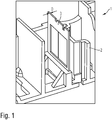
1 eine erfindungsgemäße Baugruppe aufweisend ein Trägerelement und ein umspritztes Federelement gemäß der ersten Ausführungsform, -
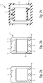
2a das Federelement gemäß einer ersten Ausführungsform, -
2b das mit einem Kunststoff umspritzte Federelement gemäß der ersten Ausführungsform, -
2c ein mit einem Kunststoff umspritztes Federelement gemäß einer zweiten Ausführungsform, -
3A ein erstes Spritzgießwerkzeug mit geöffneten Formhälften zur Herstellung eines Vorspritzlings, -
3B das erste Spritzgießwerkzeug mit geschlossenen Formhälften während der Herstellung des Vorspritzlings, -
4A ein zweites Spritzgießwerkzeug mit geschlossenen Formhälften während der Herstellung der Baugruppe, und -
4B das zweite Spritzgießwerkzeug mit geöffneten Formhälften nach der Herstellung der Baugruppe.
-
1 an assembly according to the invention comprising a carrier element and an overmolded spring element according to the first embodiment, -
2a the spring element according to a first embodiment, -
2 B the spring element overmolded with a plastic according to the first embodiment, -
2c a spring element overmolded with a plastic according to a second embodiment, -
3A a first injection mold with opened mold halves for producing a pre-molded part, -
3B the first injection mold with closed mold halves during the production of the pre-molded part, -
4A a second injection mold with closed mold halves during the manufacture of the assembly, and -
4B the second injection mold with the mold halves open after the assembly has been manufactured.
In der
Die in der
In den
In der
Nachfolgend wird das Verfahren zur Herstellung der Baugruppe
In den
Im vorliegenden Fall wird das erstes Ende
Zur Bildung des ersten Kunststoffabschnitts
Nachdem der Vorspritzling
Es wird also das mit der ersten Kunststoffschmelze
Im Ergebnis wird die Baugruppe
Claims (15)
Priority Applications (1)
| Application Number | Priority Date | Filing Date | Title |
|---|---|---|---|
| DE102018106295.8A DE102018106295B4 (en) | 2018-03-19 | 2018-03-19 | Method for producing an assembly for an operating element |
Applications Claiming Priority (1)
| Application Number | Priority Date | Filing Date | Title |
|---|---|---|---|
| DE102018106295.8A DE102018106295B4 (en) | 2018-03-19 | 2018-03-19 | Method for producing an assembly for an operating element |
Publications (2)
| Publication Number | Publication Date |
|---|---|
| DE102018106295A1 DE102018106295A1 (en) | 2019-09-19 |
| DE102018106295B4 true DE102018106295B4 (en) | 2019-12-19 |
Family
ID=67774397
Family Applications (1)
| Application Number | Title | Priority Date | Filing Date |
|---|---|---|---|
| DE102018106295.8A Active DE102018106295B4 (en) | 2018-03-19 | 2018-03-19 | Method for producing an assembly for an operating element |
Country Status (1)
| Country | Link |
|---|---|
| DE (1) | DE102018106295B4 (en) |
Citations (4)
| Publication number | Priority date | Publication date | Assignee | Title |
|---|---|---|---|---|
| DE10336187A1 (en) | 2003-08-07 | 2005-03-17 | Daimlerchrysler Ag | Hybrid component and associated manufacturing method |
| DE60120894T2 (en) | 2000-12-26 | 2007-01-11 | The Furukawa Electric Co., Ltd. | Manufacturing method of an antenna |
| US20130082415A1 (en) | 2011-09-30 | 2013-04-04 | Apple Inc. | Injection molding tool with integrated gate removal for high-volume manufacturing |
| DE102016100743A1 (en) | 2016-01-18 | 2017-07-20 | Benteler Automobiltechnik Gmbh | Bearing shoe for the storage of a leaf spring end of a leaf spring |
-
2018
- 2018-03-19 DE DE102018106295.8A patent/DE102018106295B4/en active Active
Patent Citations (4)
| Publication number | Priority date | Publication date | Assignee | Title |
|---|---|---|---|---|
| DE60120894T2 (en) | 2000-12-26 | 2007-01-11 | The Furukawa Electric Co., Ltd. | Manufacturing method of an antenna |
| DE10336187A1 (en) | 2003-08-07 | 2005-03-17 | Daimlerchrysler Ag | Hybrid component and associated manufacturing method |
| US20130082415A1 (en) | 2011-09-30 | 2013-04-04 | Apple Inc. | Injection molding tool with integrated gate removal for high-volume manufacturing |
| DE102016100743A1 (en) | 2016-01-18 | 2017-07-20 | Benteler Automobiltechnik Gmbh | Bearing shoe for the storage of a leaf spring end of a leaf spring |
Also Published As
| Publication number | Publication date |
|---|---|
| DE102018106295A1 (en) | 2019-09-19 |
Similar Documents
| Publication | Publication Date | Title |
|---|---|---|
| EP4025752B1 (en) | Actuation device for installing on a vehicle part, vehicle, and actuation method for initiating a vehicle function | |
| EP2025213B1 (en) | Sensor module with a housing which may be mounted on a wall | |
| DE102017104979A1 (en) | Control panel mounting with improved leaf spring element attachment | |
| EP3307586B1 (en) | Guide sleeve for a vehicle seat | |
| DE102014015715A1 (en) | Multipole electrical connector part | |
| DE102009002197A1 (en) | Fastening device for a cable | |
| EP1763917B1 (en) | Housing part for a drive unit and method and tool for the production thereof | |
| DE102018106295B4 (en) | Method for producing an assembly for an operating element | |
| EP2588766B1 (en) | Fastening device | |
| EP2189763A2 (en) | Device and method for assembling a housing in a predefined position relative to a reference object | |
| EP4312008B1 (en) | Sensor assembly with a retaining device and a temperature sensor unit | |
| EP2762733B1 (en) | Fastening element | |
| DE102015011597A1 (en) | Steering wheel unit and method for its manufacture | |
| DE102012105352A1 (en) | positioning | |
| EP3419820B1 (en) | Method for producing a sealing element | |
| EP3452791A1 (en) | Sensor element for a motor vehicle | |
| DE102008000965A1 (en) | Drive for adjusting device that is utilized for external force-actuated longitudinal adjustment of motor vehicle seat, has housing part with inserted locking piece inserted into assembly bracket, which holds part and locking piece together | |
| WO2021004691A1 (en) | Warning device, which can be produced in a variety of ways, for monitoring a filling level of a container, injection mould and manufacturing method | |
| EP3430288B1 (en) | Adjusting spindle arrangement for a linear drive | |
| EP1612917B1 (en) | Housing part including an axial play compensating element, and corresponding manufacturing method | |
| DE102015002958A1 (en) | Method for producing a plastic part and plastic part | |
| EP2620570A2 (en) | Striker assembly for door locks of vehicle doors | |
| DE102012218901A1 (en) | Sensor device with positioning | |
| DE102020100356B4 (en) | Wheel speed sensor housing for a motor vehicle with a sleeve element and a molded locking hook, method and arrangement | |
| EP3489531A1 (en) | Method for connecting one component with a second component |
Legal Events
| Date | Code | Title | Description |
|---|---|---|---|
| R012 | Request for examination validly filed | ||
| R016 | Response to examination communication | ||
| R018 | Grant decision by examination section/examining division | ||
| R020 | Patent grant now final |