DE102018101552B4 - Arrangement with a receipt printer arranged in a housing - Google Patents
Arrangement with a receipt printer arranged in a housing Download PDFInfo
- Publication number
- DE102018101552B4 DE102018101552B4 DE102018101552.6A DE102018101552A DE102018101552B4 DE 102018101552 B4 DE102018101552 B4 DE 102018101552B4 DE 102018101552 A DE102018101552 A DE 102018101552A DE 102018101552 B4 DE102018101552 B4 DE 102018101552B4
- Authority
- DE
- Germany
- Prior art keywords
- receipt
- guide
- flap
- unit
- guide element
- Prior art date
- Legal status (The legal status is an assumption and is not a legal conclusion. Google has not performed a legal analysis and makes no representation as to the accuracy of the status listed.)
- Active
Links
- 230000006835 compression Effects 0.000 claims description 8
- 238000007906 compression Methods 0.000 claims description 8
- 125000006850 spacer group Chemical group 0.000 description 5
- 230000001419 dependent effect Effects 0.000 description 1
- 238000011161 development Methods 0.000 description 1
- 230000018109 developmental process Effects 0.000 description 1
- 238000012423 maintenance Methods 0.000 description 1
- 238000004519 manufacturing process Methods 0.000 description 1
- 238000000034 method Methods 0.000 description 1
- 230000007704 transition Effects 0.000 description 1
Images

Classifications
-
- B—PERFORMING OPERATIONS; TRANSPORTING
- B41—PRINTING; LINING MACHINES; TYPEWRITERS; STAMPS
- B41J—TYPEWRITERS; SELECTIVE PRINTING MECHANISMS, i.e. MECHANISMS PRINTING OTHERWISE THAN FROM A FORME; CORRECTION OF TYPOGRAPHICAL ERRORS
- B41J13/00—Devices or arrangements of selective printing mechanisms, e.g. ink-jet printers or thermal printers, specially adapted for supporting or handling copy material in short lengths, e.g. sheets
- B41J13/10—Sheet holders, retainers, movable guides, or stationary guides
- B41J13/12—Sheet holders, retainers, movable guides, or stationary guides specially adapted for small cards, envelopes, or the like, e.g. credit cards, cut visiting cards
-
- B—PERFORMING OPERATIONS; TRANSPORTING
- B41—PRINTING; LINING MACHINES; TYPEWRITERS; STAMPS
- B41J—TYPEWRITERS; SELECTIVE PRINTING MECHANISMS, i.e. MECHANISMS PRINTING OTHERWISE THAN FROM A FORME; CORRECTION OF TYPOGRAPHICAL ERRORS
- B41J29/00—Details of, or accessories for, typewriters or selective printing mechanisms not otherwise provided for
- B41J29/12—Guards, shields or dust excluders
- B41J29/13—Cases or covers
-
- B—PERFORMING OPERATIONS; TRANSPORTING
- B41—PRINTING; LINING MACHINES; TYPEWRITERS; STAMPS
- B41J—TYPEWRITERS; SELECTIVE PRINTING MECHANISMS, i.e. MECHANISMS PRINTING OTHERWISE THAN FROM A FORME; CORRECTION OF TYPOGRAPHICAL ERRORS
- B41J11/00—Devices or arrangements of selective printing mechanisms, e.g. ink-jet printers or thermal printers, for supporting or handling copy material in sheet or web form
- B41J11/0045—Guides for printing material
-
- B—PERFORMING OPERATIONS; TRANSPORTING
- B41—PRINTING; LINING MACHINES; TYPEWRITERS; STAMPS
- B41J—TYPEWRITERS; SELECTIVE PRINTING MECHANISMS, i.e. MECHANISMS PRINTING OTHERWISE THAN FROM A FORME; CORRECTION OF TYPOGRAPHICAL ERRORS
- B41J15/00—Devices or arrangements of selective printing mechanisms, e.g. ink-jet printers or thermal printers, specially adapted for supporting or handling copy material in continuous form, e.g. webs
- B41J15/04—Supporting, feeding, or guiding devices; Mountings for web rolls or spindles
- B41J15/042—Supporting, feeding, or guiding devices; Mountings for web rolls or spindles for loading rolled-up continuous copy material into printers, e.g. for replacing a used-up paper roll; Point-of-sale printers with openable casings allowing access to the rolled-up continuous copy material
-
- B—PERFORMING OPERATIONS; TRANSPORTING
- B41—PRINTING; LINING MACHINES; TYPEWRITERS; STAMPS
- B41J—TYPEWRITERS; SELECTIVE PRINTING MECHANISMS, i.e. MECHANISMS PRINTING OTHERWISE THAN FROM A FORME; CORRECTION OF TYPOGRAPHICAL ERRORS
- B41J29/00—Details of, or accessories for, typewriters or selective printing mechanisms not otherwise provided for
-
- B—PERFORMING OPERATIONS; TRANSPORTING
- B41—PRINTING; LINING MACHINES; TYPEWRITERS; STAMPS
- B41J—TYPEWRITERS; SELECTIVE PRINTING MECHANISMS, i.e. MECHANISMS PRINTING OTHERWISE THAN FROM A FORME; CORRECTION OF TYPOGRAPHICAL ERRORS
- B41J3/00—Typewriters or selective printing or marking mechanisms characterised by the purpose for which they are constructed
- B41J3/407—Typewriters or selective printing or marking mechanisms characterised by the purpose for which they are constructed for marking on special material
- B41J3/4075—Tape printers; Label printers
-
- G—PHYSICS
- G07—CHECKING-DEVICES
- G07G—REGISTERING THE RECEIPT OF CASH, VALUABLES, OR TOKENS
- G07G5/00—Receipt-giving machines
-
- B—PERFORMING OPERATIONS; TRANSPORTING
- B41—PRINTING; LINING MACHINES; TYPEWRITERS; STAMPS
- B41J—TYPEWRITERS; SELECTIVE PRINTING MECHANISMS, i.e. MECHANISMS PRINTING OTHERWISE THAN FROM A FORME; CORRECTION OF TYPOGRAPHICAL ERRORS
- B41J15/00—Devices or arrangements of selective printing mechanisms, e.g. ink-jet printers or thermal printers, specially adapted for supporting or handling copy material in continuous form, e.g. webs
- B41J15/04—Supporting, feeding, or guiding devices; Mountings for web rolls or spindles
- B41J15/046—Supporting, feeding, or guiding devices; Mountings for web rolls or spindles for the guidance of continuous copy material, e.g. for preventing skewed conveyance of the continuous copy material
Landscapes
- Physics & Mathematics (AREA)
- General Physics & Mathematics (AREA)
- Cash Registers Or Receiving Machines (AREA)
- Accessory Devices And Overall Control Thereof (AREA)
Abstract
Anordnung mit einem in einem Gehäuse (100) angeordneten Bondrucker (12) zum Drucken eines Bons (24), wobei das Gehäuse (100) eine schwenkbare Klappe (16) umfasst, die in einem geöffneten Zustand einen Zugriff auf den Bondrucker (12) ermöglicht und die in einem geschlossenen Zustand den Zugriff auf den Bondrucker (12) verhindert, wobei die Klappe (16) eine Öffnung (18) hat, durch die ein vom Bondrucker (12) gedruckter Bon (24) im geschlossenen Zustand der Klappe (16) ausgebbar ist, wobei die Anordnung (10) eine Bonausgabeeinheit (14) hat, die im geschlossenen Zustand der Klappe (16) dem Bondrucker (12) gegenüberliegend in der Öffnung (18) der Klappe (16) angeordnet ist, wobei die Bonausgabeeinheit (14) mindestens eine erste Bonführungseinheit (102) hat, wobei die Bonausgabeeinheit (14) mindestens ein erstes elastisch verformbares Element zur federnden Lagerung zumindest eines Bauteils der ersten Bonführungseinheit (102) hat, der Bondrucker (12) eine zweite Bonführungseinheit (20) hat, und wobei die erste Bonführungseinheit (102) beim Bewegen vom geöffneten Zustand in den geschlossenen Zustand der Klappe (16) mit der zweiten Bonführungseinheit (20) in Eingriff gebracht wird, dadurch gekennzeichnet, dass die erste Bonführungseinheit (102) der Bonausgabeeinheit (14) ein erstes Führungselement (26) und mindestens ein zweites Führungselement (28) hat, dass das erste Führungselement (26) und das zweite Führungselement (28) jeweils relativ zu der Klappe (16) um eine Drehachse (A, B) schwenkbar angeordnet sind und dass die Bonausgabeeinheit (14) ein zweites elastisch verformbares Element hat, das das erste Führungselement (26) und das zweite Führungselement (28) miteinander verbindet.Arrangement with a receipt printer (12) arranged in a housing (100) for printing a receipt (24), the housing (100) comprising a pivotable flap (16) which, when open, enables access to the receipt printer (12) and which prevents access to the receipt printer (12) in a closed state, the flap (16) having an opening (18) through which a receipt (24) printed by the receipt printer (12) in the closed state of the flap (16) The arrangement (10) has a receipt dispensing unit (14) which, when the flap (16) is closed, is arranged opposite the receipt printer (12) in the opening (18) of the flap (16), the receipt dispensing unit (14 ) has at least one first receipt guide unit (102), the receipt output unit (14) having at least one first elastically deformable element for resiliently mounting at least one component of the first receipt guide unit (102), the receipt printer (12) having a second receipt guide unit (20), u nd wherein the first receipt guide unit (102) is brought into engagement with the second receipt guide unit (20) when the flap (16) is moved from the open state to the closed state, characterized in that the first receipt guide unit (102) of the receipt output unit (14) first guide element (26) and at least one second guide element (28) that the first guide element (26) and the second guide element (28) are each arranged to be pivotable relative to the flap (16) about an axis of rotation (A, B) and that the receipt dispensing unit (14) has a second elastically deformable element which connects the first guide element (26) and the second guide element (28) to one another.
Description
Die Erfindung betrifft eine Anordnung mit einem in einem Gehäuse angeordneten Bondrucker zum Drucken eines Bons. Das Gehäuse umfasst eine schwenkbare Klappe, die in einem geöffneten Zustand einen Zugriff auf den Bondrucker ermöglicht und die in einem geschlossenen Zustand den Zugriff auf den Bondrucker verhindert. Die Klappe hat eine Öffnung, durch die ein vom Bondrucker gedruckter Bon im geschlossenen Zustand der Klappe ausgebbar ist.The invention relates to an arrangement with a receipt printer arranged in a housing for printing a receipt. The housing comprises a pivotable flap which, in an open state, enables access to the receipt printer and which, in a closed state, prevents access to the receipt printer. The flap has an opening through which a receipt printed by the receipt printer can be output when the flap is closed.
Gemäß dem Stand der Technik muss beim Bewegen der Klappe vom geöffneten in den geschlossenen Zustand die Öffnung der Klappe in eine dem Bondrucker gegenüberliegende Position gebracht werden, damit eine Entnahme des durch den Bondrucker gedruckten Bons möglich ist. Durch Form- und Lagetoleranzen kann sich die Position der Öffnung in Relation zu dem Bondrucker derart verändern, dass der Bon nicht mehr zuverlässig durch die Öffnung ausgegeben werden kann. Beispielsweise kann sich die Position der Öffnung in Relation zu dem Bondrucker vertikal um bis zu ±2 mm verschieben, so dass der Bon bei der Ausgabe aus dem Bondrucker gegen eine Innenseite der Klappe stößt und von der Öffnung weggebogen wird. Eine zuverlässige Ausgabe des Bons ist somit nicht mehr gegeben.According to the prior art, when the flap is moved from the open to the closed state, the opening of the flap must be brought into a position opposite the receipt printer so that the receipt printed by the receipt printer can be removed. Due to shape and position tolerances, the position of the opening in relation to the receipt printer can change in such a way that the receipt can no longer be reliably output through the opening. For example, the position of the opening in relation to the receipt printer can shift vertically by up to ± 2 mm, so that the receipt hits an inside of the flap when it is output from the receipt printer and is bent away from the opening. A reliable issue of the receipt is therefore no longer given.
Das Dokument
Das Dokument
Das Dokument
Ausgehend vom bekannten Stand der Technik ist es Aufgabe der Erfindung, eine Anordnung mit einem in einem Gehäuse angeordneten Bondrucker anzugeben, bei der ein durch den Bondrucker gedruckter Bon zuverlässig ausgegeben wird.Starting from the known prior art, it is the object of the invention to provide an arrangement with a receipt printer arranged in a housing, in which a receipt printed by the receipt printer is reliably output.
Diese Aufgabe wird durch eine Anordnung mit den Merkmalen des Anspruchs 1 gelöst. Vorteilhafte Weiterbildungen sind in den abhängigen Ansprüchen angegeben.This object is achieved by an arrangement having the features of claim 1. Advantageous further developments are given in the dependent claims.
Die erfindungsgemäße Anordnung hat einen in einem Gehäuse angeordneten Bondrucker zum Drucken eines Bons. Das Gehäuse umfasst eine vorzugsweise um eine Drehachse schwenkbare Klappe, die in einem geöffneten Zustand einen Zugriff auf den Bondrucker ermöglicht und die in einem geschlossenen Zustand den Zugriff auf den Bondrucker verhindert. Die Klappe hat eine Öffnung, durch die ein vom Bondrucker gedruckter Bon im geschlossenen Zustand der Klappe ausgebbar ist. Die Anordnung hat ferner eine Bonausgabeeinheit, die im geschlossenen Zustand der Klappe dem Bondrucker gegenüberliegend in der Öffnung der Klappe angeordnet ist. Die Bonausgabeeinheit hat mindestens eine erste Bonführungseinheit. Ferner hat die Bonausgabeeinheit mindestens ein erstes elastisch verformbares Element zur federnden Lagerung zumindest eines Bauteils der ersten Bonführungseinheit. Der Bondrucker hat eine zweite Bonführungseinheit. Die erste Bonführungseinheit wird beim Bewegen vom geöffneten Zustand in den geschlossenen Zustand der Klappe mit der zweiten Bonführungseinheit in Eingriff gebracht. Durch die erfindungsgemäße Anordnung wird somit eine zuverlässige Ausgabe des durch den Bondrucker gedruckten Bons erreicht.The arrangement according to the invention has a receipt printer arranged in a housing for printing a receipt. The housing comprises a flap which is preferably pivotable about an axis of rotation and which enables access to the receipt printer in an open state and which prevents access to the receipt printer in a closed state. The flap has an opening through which a receipt printed by the receipt printer can be output when the flap is closed. The arrangement also has a receipt output unit which, when the flap is closed, is arranged opposite the receipt printer in the opening of the flap. The receipt issuing unit has at least one first receipt guide unit. Furthermore, the receipt dispensing unit has at least one first elastically deformable element for the resilient mounting of at least one component of the first receipt guide unit. The receipt printer has a second receipt guide unit. The first receipt guide unit is brought into engagement with the second receipt guide unit when the flap is moved from the open state to the closed state. The arrangement according to the invention thus achieves a reliable output of the receipt printed by the receipt printer.
Vorzugsweise wird der durch den Bondrucker gedruckte Bon durch die Bonausgabeeinheit von dem innerhalb des Gehäuses angeordneten Bondrucker durch die Öffnung der Klappe zu einer Außenseite des Gehäuses geführt. Hierzu steht die erste Bonführungseinheit der Bonausgabeeinheit im geschlossenen Zustand der Klappe mit der zweiten Bonführungseinheit des Bondruckers in Eingriff, so dass eine lückenlose Führung des Bons möglich ist. Beim Bewegen der Klappe vom geöffneten in den geschlossenen Zustand wird die Bonausgabeeinheit vorzugsweise auf einer Kreisbahn in eine dem Bondrucker gegenüberliegenden Position gebracht. Durch diese Bewegung wird die erste Bonführungseinheit mit der zweiten Bonführungseinheit in Eingriff gebracht. Dabei werden durch die federnde Lagerung zumindest eines Bauteils der Bonausgabeeinheit insbesondere Form- und Lagetoleranzen ausgeglichen, wodurch eine präzise und zuverlässige Verbindung zwischen der ersten Bonführungseinheit und der zweiten Bonführungseinheit ermöglicht wird.The receipt printed by the receipt printer is preferably fed through the receipt output unit from the receipt printer arranged inside the housing through the opening of the flap to an outside of the housing. For this purpose, the first receipt guide unit of the receipt issuing unit is in engagement with the second receipt guide unit of the receipt printer when the flap is closed, so that the receipt can be guided without gaps. When the flap is moved from the open to the closed state, the receipt dispensing unit is preferably brought into a position opposite the receipt printer on a circular path. This movement brings the first receipt guide unit into engagement with the second receipt guide unit. The resilient mounting of at least one component of the receipt dispensing unit compensates for shape and position tolerances in particular, which enables a precise and reliable connection between the first receipt guide unit and the second receipt guide unit.
Insbesondere werden durch die federnde Lagerung zumindest eines Bauteils der Bonausgabeeinheit Lagetoleranzen ausgeglichen, die dazu führen, dass sich die Position der Klappe oder die Position der ersten Bonführungseinheit der Bonausgabeeinheit in Relation zu dem Bondrucker vertikal um bis zu 2 mm nach oben oder unten verschiebt.In particular, the resilient mounting of at least one component of the receipt issuing unit compensates for positional tolerances which lead to the position of the flap or the position of the first receipt guiding unit of the receipt issuing unit shifting vertically up or down by up to 2 mm in relation to the receipt printer.
Es ist vorteilhaft, wenn die erste Bonführungseinheit der Bonausgabeeinheit ein erstes Führungselement und mindestens ein zweites Führungselement hat. Beispielsweise können das erste Führungselement und das zweite Führungselement derart angeordnet sein, dass bei bestimmungsgemäßem Gebrauch der Anordnung die zweite Bonführungseinheit im geschlossenen Zustand der Klappe zumindest teilweise zwischen dem ersten Führungselement und dem zweiten Führungselement angeordnet ist. Hierdurch wird im geschlossenen Zustand der Klappe der lückenlose Übergang zwischen der ersten Bonführungseinheit und der zweiten Bonführungseinheit realisiert. Insbesondere können das erste Führungselement und das zweite Führungselement zueinander beweglich angeordnet sein. Hierdurch können Form- und Lagetoleranzen bei der Bewegung der Klappe von dem geöffneten in den geschlossenen Zustand noch besser ausgeglichen werden.It is advantageous if the first receipt guide unit of the receipt dispensing unit has a first guide element and at least one second guide element. For example, the first guide element and the second guide element can be arranged such that when the arrangement is used as intended, the second receipt guide unit is at least partially arranged between the first guide element and the second guide element in the closed state of the flap. In this way, in the closed state of the flap, the seamless transition between the first receipt guide unit and the second receipt guide unit is realized. In particular, the first guide element and the second guide element can be arranged to be movable relative to one another. As a result, shape and position tolerances when moving the flap from the open to the closed state can be compensated for even better.
Es ist vorteilhaft, wenn das erste Führungselement und/oder das zweite Führungselement jeweils relativ zu der Klappe um eine Drehachse schwenkbar angeordnet sind. Die Schwenkbewegungen des ersten Führungselements bzw. des zweiten Führungselements dienen dem Ausgleich der Form- und Lagetoleranzen bei der Bewegung der Klappe von dem geöffneten in den geschlossenen Zustand. Eine schwenkbare Lagerung des ersten Führungselements und/oder des zweiten Führungselements jeweils um eine Drehachse ist zudem besonders einfach zu realisieren.It is advantageous if the first guide element and / or the second guide element are each arranged to be pivotable about an axis of rotation relative to the flap. The pivoting movements of the first guide element and the second guide element serve to compensate for the shape and position tolerances when moving the flap from the open to the closed state. A pivotable mounting of the first guide element and / or the second guide element in each case about an axis of rotation is also particularly easy to implement.
Es ist vorteilhaft, wenn das erste elastisch verformbare Element eine Druckfeder ist, die beim Bewegen vom geöffneten Zustand in den geschlossenen Zustand der Klappe das erste Führungselement gegen einen dem ersten Führungselement zugeordneten ersten Bereich der zweiten Bonführungseinheit des Bondruckers drückt. Bei dem ersten Bereich der zweiten Bonführungseinheit kann es sich insbesondere um eine Kontaktfläche handeln, die dem ersten Führungselement im geschlossenen Zustand der Klappe gegenüberliegend angeordnet ist. Hierdurch wird verhindert, dass zwischen der zweiten Bonführungseinheit und dem ersten Führungselement ein Spalt entsteht, durch den der Bon aus der Führung geraten könnte.It is advantageous if the first elastically deformable element is a compression spring which, when the flap is moved from the open state to the closed state, presses the first guide element against a first region of the second receipt guide unit of the receipt printer assigned to the first guide element. The first area of the second receipt guide unit can in particular be a contact surface which is arranged opposite the first guide element in the closed state of the flap. This prevents the creation of a gap between the second receipt guide unit and the first guide element through which the receipt could get out of the guide.
Vorzugsweise hat die Bonausgabeeinheit ein zweites elastisch verformbares Element, das das erste Führungselement und das zweite Führungselement miteinander verbindet. Das zweite elastisch verformbare Element verbindet das erste Führungselement und das zweite Führungselement insbesondere derart, dass diese innerhalb eines bestimmten Toleranzbereiches relativ zueinander bewegt werden können.The receipt dispensing unit preferably has a second elastically deformable element which connects the first guide element and the second guide element to one another. The second elastically deformable element connects the first guide element and the second guide element in particular in such a way that they can be moved relative to one another within a certain tolerance range.
Vorzugsweise ist das zweite elastisch verformbare Element eine Zugfeder, die beim Bewegen vom geöffneten Zustand in den geschlossenen Zustand der Klappe das zweite Führungselement gegen einen dem zweiten Führungselement zugeordneten zweiten Bereich der zweiten Bonführungseinheit des Bondruckers drückt. Insbesondere können das erste Führungselement und das zweite Führungselement derart angeordnet sein, dass bei bestimmungsgemäßem Gebrauch der Anordnung das erste Führungselement und das zweite Führungselement im geschlossenen Zustand der Klappe um die zweite Bonführungseinheit herumgreifen. Hierdurch ist ein fester Eingriff bzw. Kontakt zwischen der durch das erste Führungselement und das zweite Führungselement gebildeten ersten Bonführungseinheit und der zweiten Bonführungseinheit möglich.The second elastically deformable element is preferably a tension spring which, when the flap is moved from the open state to the closed state, presses the second guide element against a second region of the second receipt guide unit of the receipt printer assigned to the second guide element. In particular, the first guide element and the second guide element can be arranged such that when the arrangement is used as intended, the first guide element and the second guide element grip around the second receipt guide unit when the flap is closed. This enables firm engagement or contact between the first receipt guide unit formed by the first guide element and the second guide element and the second receipt guide unit.
Es ist vorteilhaft, wenn im geschlossenen Zustand der Klappe der Bon zur Ausgabe aus der Anordnung zwischen dem ersten Führungselement und dem zweiten Führungselement geführt wird. Hierdurch wird der Weg, entlang dessen der Bon geführt wird, in zwei Richtungen, insbesondere nach oben und nach unten, begrenzt. Hierdurch ist eine zuverlässige Führung des Bons gewährleistet.It is advantageous if, in the closed state of the flap, the receipt is guided for output from the arrangement between the first guide element and the second guide element. As a result, the path along which the receipt is guided is limited in two directions, in particular upwards and downwards. This ensures reliable guidance of the receipt.
Es ist vorteilhaft, wenn die Bonausgabeeinheit eine Präsentiereinheit zur Ausgabe des Bons hat, die auf einer Außenseite der Klappe angeordnet ist. Insbesondere wird der Bon durch die Präsentiereinheit entlang eines gebogenen Weges geführt. Hierdurch wird die Steifigkeit des Bons erhöht, wodurch sich der Bon leichter bewegen lässt. Ferner kann hierdurch verhindert werden, dass eine Beschädigung und/oder Manipulation des Bondruckers, beispielsweise mithilfe eines starren, spitzen Gegenstandes, erfolgen kann. Während ein Bon üblicherweise flexibel ist und damit entlang des gebogenen Weges geführt werden kann, ist dieser Weg für einen starren Gegenstand versperrt.It is advantageous if the receipt issuing unit has a presentation unit for issuing the receipt, which is arranged on an outside of the flap. In particular, the receipt is guided by the presentation unit along a curved path. This increases the stiffness of the receipt, making the receipt easier to move. Furthermore, this can prevent damage to and / or manipulation of the receipt printer, for example with the aid of a rigid, pointed object. While a receipt is usually flexible and can thus be guided along the curved path, this path is blocked for a rigid object.
Es ist vorteilhaft, wenn das erste Führungselement und/oder das zweite Führungselement jeweils um eine Drehachse schwenkbar an der Präsentiereinheit angeordnet sind. Insbesondere ist die Präsentiereinheit an der Klappe angeordnet, so dass das erste Führungselement und/oder das zweite Führungselement jeweils um eine Drehachse schwenkbar an der Klappe angeordnet sind. Die Schwenkbewegungen des ersten Führungselements bzw. des zweiten Führungselements gleichen wiederum die Toleranzen bei der Bewegung der Klappe von dem geöffneten in den geschlossenen Zustand aus.It is advantageous if the first guide element and / or the second guide element are each arranged on the presentation unit so as to be pivotable about an axis of rotation. In particular, the presentation unit is arranged on the flap, so that the first guide element and / or the second guide element are each arranged on the flap so that they can pivot about an axis of rotation. The pivoting movements of the first guide element and the second guide element, in turn, are the same Tolerances in the movement of the flap from the open to the closed state.
Vorzugsweise umfasst die Präsentiereinheit ein erstes Führungsteilstück und ein zweites Führungsteilstück. Im geschlossenen Zustand der Klappe wird der Bon zur Ausgabe aus der Anordnung zwischen dem ersten Führungsteilstück und dem zweiten Führungsteilstück geführt. Die Verwendung der beiden Führungsteilstücke erlaubt eine einfache Fertigung und Montage der Präsentiereinheit.The presentation unit preferably comprises a first guide section and a second guide section. In the closed state of the flap, the receipt is guided for output from the arrangement between the first guide section and the second guide section. The use of the two guide sections allows simple manufacture and assembly of the presentation unit.
Das Gehäuse kann außer dem Bondrucker auch weitere Bauelemente umfassen, beispielsweise eine Leseeinheit für Magnetkarten, eine Steuereinheit zur Steuerung von Abläufen der Anordnung und/oder ein Ein-/Ausgabefach für Wertscheine und/oder Münzen.In addition to the receipt printer, the housing can also include other components, for example a reading unit for magnetic cards, a control unit for controlling processes of the arrangement and / or an input / output compartment for notes of value and / or coins.
Auf einer Außenseite der Klappe können eine Eingabeeinheit, beispielsweise eine Tastatur, und/oder eine Ausgabeeinheit, beispielsweise ein Bildschirm, angeordnet sein.An input unit, for example a keyboard, and / or an output unit, for example a screen, can be arranged on an outside of the flap.
Die Anordnung kann insbesondere ein Selbstbedienungsautomat sein, beispielsweise ein Geldautomat, ein Kassensystem, ein Rücknahmeautomat oder ein Lotterie-Terminal.The arrangement can in particular be a self-service machine, for example an ATM, a cash register system, a return machine or a lottery terminal.
Es ist vorteilhaft, wenn die Bonausgabeeinheit die Öffnung der Klappe vollständig verdeckt, so dass im geschlossenen Zustand der Klappe kein Zugriff auf den Bondrucker und/oder andere Bauelemente, die innerhalb des Gehäuses angeordnet sind, möglich ist.It is advantageous if the receipt dispensing unit completely covers the opening of the flap, so that when the flap is closed, access to the receipt printer and / or other components which are arranged within the housing is not possible.
Weitere Merkmale und Vorteile der Erfindung ergeben sich aus der folgenden Beschreibung, die die Erfindung anhand von Ausführungsbeispielen im Zusammenhang mit den beigefügten Figuren näher erläutert.Further features and advantages of the invention emerge from the following description, which explains the invention in more detail on the basis of exemplary embodiments in connection with the accompanying figures.
Es zeigen:
-
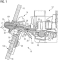
1 eine Schnittdarstellung einer Anordnung mit einem in einem Gehäuse angeordneten Bondrucker zum Drucken eines Bons und mit einer Bonausgabeeinheit gemäß einem Ausführungsbeispiel; -
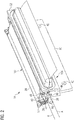
2 eine perspektivische Darstellung der Bonausgabeeinheit zum Ausgeben des Bons aus der Anordnung gemäß dem Ausführungsbeispiel nach1 ; -
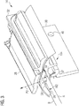
3 eine perspektivische Schnittdarstellung der Bonausgabeeinheit gemäß dem Ausführungsbeispiel nach1 ; -
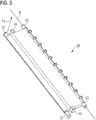
4 ein erstes Führungselement der Bonausgabeeinheit gemäß dem Ausführungsbeispiel nach1 ; -
5 ein zweites Führungselement der Bonausgabeeinheit gemäß dem Ausführungsbeispiel nach1 ; -
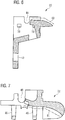
6 eine Schnittdarstellung eines ersten Führungsteilstücks der Bonausgabeeinheit gemäß dem Ausführungsbeispiel nach1 ; und -
7 eine Schnittdarstellung eines zweiten Führungsteilstücks der Bonausgabeeinheit gemäß dem Ausführungsbeispiel nach1 .
-
1 a sectional view of an arrangement with a receipt printer arranged in a housing for printing a receipt and with a receipt output unit according to an embodiment; -
2 a perspective view of the receipt issuing unit for issuing the receipt from the arrangement according to the embodiment of FIG1 ; -
3 a perspective sectional view of the receipt dispensing unit according to the embodiment of FIG1 ; -
4th a first guide element of the receipt dispensing unit according to the embodiment1 ; -
5 a second guide element of the receipt dispensing unit according to the embodiment according to FIG1 ; -
6th a sectional view of a first guide portion of the receipt dispensing unit according to the embodiment of FIG1 ; and -
7th a sectional view of a second guide section of the receipt dispensing unit according to the embodiment of FIG1 .
Das Gehäuse
Der Bondrucker
Die Bonausgabeeinheit
Das erste Führungselement
Die Bonausgabeeinheit
Die erste Bonführungseinheit
Die Präsentiereinheit
BezugszeichenlisteList of reference symbols
- 1010
- Anordnungarrangement
- 1212th
- BondruckerBon printer
- 1414th
- BonausgabeeinheitReceipt issuing unit
- 1616
- Klappeflap
- 1818th
- Öffnungopening
- 20, 10220, 102
- BonführungseinheitReceipt guide unit
- 22, 2322, 23
- BereichArea
- 2424
- BonReceipt
- 26, 2826, 28
- FührungselementGuide element
- 30, 3230, 32
- FührungsteilstückGuide section
- 3434
- DruckfederCompression spring
- 3636
- ZugfederTension spring
- 3838
- Schraubescrew
- 4040
- Lochhole
- 42, 4342, 43
- AbstandshalteelementSpacer element
- 44, 4844, 48
- AusnehmungRecess
- 4646
- EinrastelementSnap-in element
- 50, 5250, 52
- Vorsprunghead Start
- 54, 5554, 55
- DrehpunktelementPivot element
- 56, 5756, 57
- FederhalteelementSpring retainer
- 5858
- EinrastlöcherSnap-in holes
- 60, 6160, 61
- Linieline
- 100100
- Gehäusecasing
- 104104
- PräsentiereinheitPresentation unit
- A, BA, B
- DrehachseAxis of rotation
- P1 bis P4P1 to P4
- Pfeilarrow
Claims (7)
Priority Applications (5)
| Application Number | Priority Date | Filing Date | Title |
|---|---|---|---|
| DE102018101552.6A DE102018101552B4 (en) | 2018-01-24 | 2018-01-24 | Arrangement with a receipt printer arranged in a housing |
| EP19152698.7A EP3533616B1 (en) | 2018-01-24 | 2019-01-21 | Assembly with a receipt printer in a housing |
| US16/256,539 US11065896B2 (en) | 2018-01-24 | 2019-01-24 | Arrangement with a receipt printer arranged in a housing |
| CN201910067838.5A CN110065313B (en) | 2018-01-24 | 2019-01-24 | Assembly with a document printer arranged in a housing |
| US17/216,497 US11827039B2 (en) | 2018-01-24 | 2021-03-29 | Arrangement with a receipt printer arranged in a housing |
Applications Claiming Priority (1)
| Application Number | Priority Date | Filing Date | Title |
|---|---|---|---|
| DE102018101552.6A DE102018101552B4 (en) | 2018-01-24 | 2018-01-24 | Arrangement with a receipt printer arranged in a housing |
Publications (2)
| Publication Number | Publication Date |
|---|---|
| DE102018101552A1 DE102018101552A1 (en) | 2019-07-25 |
| DE102018101552B4 true DE102018101552B4 (en) | 2021-05-06 |
Family
ID=65138845
Family Applications (1)
| Application Number | Title | Priority Date | Filing Date |
|---|---|---|---|
| DE102018101552.6A Active DE102018101552B4 (en) | 2018-01-24 | 2018-01-24 | Arrangement with a receipt printer arranged in a housing |
Country Status (4)
| Country | Link |
|---|---|
| US (2) | US11065896B2 (en) |
| EP (1) | EP3533616B1 (en) |
| CN (1) | CN110065313B (en) |
| DE (1) | DE102018101552B4 (en) |
Citations (1)
| Publication number | Priority date | Publication date | Assignee | Title |
|---|---|---|---|---|
| JP2010143143A (en) * | 2008-12-19 | 2010-07-01 | Sato Knowledge & Intellectual Property Institute | Double-sided printing thermal printer |
Family Cites Families (9)
| Publication number | Priority date | Publication date | Assignee | Title |
|---|---|---|---|---|
| JP3545830B2 (en) * | 1995-04-27 | 2004-07-21 | 東芝テック株式会社 | Label printer |
| JP3449851B2 (en) * | 1996-01-30 | 2003-09-22 | 富士通株式会社 | Printer with automatic paper thickness tracking mechanism |
| JP2009083448A (en) * | 2007-10-03 | 2009-04-23 | Seiko Instruments Inc | Printer and issuing apparatus |
| DE102009005411A1 (en) | 2009-01-19 | 2010-07-22 | Wincor Nixdorf International Gmbh | ATM |
| JP5432050B2 (en) * | 2009-09-17 | 2014-03-05 | 東芝テック株式会社 | Portable printer |
| DE102010040177A1 (en) | 2010-09-02 | 2012-03-08 | Sielaff Gmbh & Co. Kg Automatenbau | Reverse vending machine has control device that switches touch screen from article delivery/return mode to maintenance mode when door is in open state |
| JP6250438B2 (en) * | 2014-02-28 | 2017-12-20 | 富士通コンポーネント株式会社 | Printer device |
| CN105459634B (en) * | 2014-09-05 | 2019-01-08 | 山东新北洋信息技术股份有限公司 | Paper delivery mechanism and printing equipment with the paper delivery mechanism |
| US20200171812A1 (en) * | 2018-11-29 | 2020-06-04 | Zivelo, Inc. | Interactive kiosk having self-aligning printer paper dispensing chute |
-
2018
- 2018-01-24 DE DE102018101552.6A patent/DE102018101552B4/en active Active
-
2019
- 2019-01-21 EP EP19152698.7A patent/EP3533616B1/en active Active
- 2019-01-24 CN CN201910067838.5A patent/CN110065313B/en active Active
- 2019-01-24 US US16/256,539 patent/US11065896B2/en active Active
-
2021
- 2021-03-29 US US17/216,497 patent/US11827039B2/en active Active
Patent Citations (1)
| Publication number | Priority date | Publication date | Assignee | Title |
|---|---|---|---|---|
| JP2010143143A (en) * | 2008-12-19 | 2010-07-01 | Sato Knowledge & Intellectual Property Institute | Double-sided printing thermal printer |
Also Published As
| Publication number | Publication date |
|---|---|
| US20190224998A1 (en) | 2019-07-25 |
| EP3533616B1 (en) | 2022-06-22 |
| US11065896B2 (en) | 2021-07-20 |
| US20210213763A1 (en) | 2021-07-15 |
| CN110065313A (en) | 2019-07-30 |
| CN110065313B (en) | 2022-08-09 |
| EP3533616A1 (en) | 2019-09-04 |
| DE102018101552A1 (en) | 2019-07-25 |
| US11827039B2 (en) | 2023-11-28 |
Similar Documents
| Publication | Publication Date | Title |
|---|---|---|
| EP0609672B1 (en) | Safety switch | |
| EP2316150B1 (en) | Electrical terminal | |
| EP0186737B1 (en) | Input unit for a data card containing an electronic circuit | |
| DE60203688T2 (en) | thermal printer | |
| DE102006021884B3 (en) | Length adjuster for seat of vehicle has first seat rail arranged so that in event of crash it locks bearing of unlocking flap in holder | |
| DE102007016970A1 (en) | Device of an outside door handle for preventing the door from opening in the event of a broadside collision | |
| WO2008138613A1 (en) | Locking clip for plug connector housings | |
| DE102004007390B4 (en) | Locking unit for a movable closing element | |
| DE3829109C2 (en) | Electrical switches, in particular steering column switches for motor vehicles | |
| DE102008057148B4 (en) | Railroad toggle | |
| DE102008031217B4 (en) | Locking device with a locking member for locking a functionally essential component | |
| EP1049605B1 (en) | Stick shift, especially a steering column switch for motor vehicles | |
| DE102018101552B4 (en) | Arrangement with a receipt printer arranged in a housing | |
| DE102008018738B4 (en) | On-vehicle coupling assembly of a trailer coupling | |
| DE10321233A1 (en) | printer | |
| DE10350710B4 (en) | Closure for a household appliance | |
| EP0434922B1 (en) | Storage holder for magnetic tape cassette | |
| EP3762905A1 (en) | Assembly having a card reader arranged in a housing | |
| DE3319961A1 (en) | PAPER FEEDING DEVICE FOR TYPEWRITERS OR OFFICE MACHINES WITH PAPER COMPENSATION SPLIT ARRANGED IN THE PAPER GUIDE CHANNEL | |
| EP3821507B1 (en) | Pressure relief device | |
| EP2688379B1 (en) | Electronic automation technology module | |
| EP1676761B1 (en) | Windscreen wiper device | |
| DE102021207015A1 (en) | Housing for a door drive and door drive | |
| DE102020115506A1 (en) | Locking unit for a sliding door | |
| DE102008058291B4 (en) | Housing for an electronic device |
Legal Events
| Date | Code | Title | Description |
|---|---|---|---|
| R012 | Request for examination validly filed | ||
| R016 | Response to examination communication | ||
| R018 | Grant decision by examination section/examining division | ||
| R020 | Patent grant now final | ||
| R081 | Change of applicant/patentee |
Owner name: DIEBOLD NIXDORF SYSTEMS GMBH, DE Free format text: FORMER OWNER: WINCOR NIXDORF INTERNATIONAL GMBH, 33106 PADERBORN, DE |
|
| R082 | Change of representative |